experimental investigation of fault-tolerant control ... · experimental investigation of...
TRANSCRIPT
Experimental Investigation of Fault-Tolerant Control Strategies for Quad-Inverter Converters
G. Grandi1, P. Sanjeevikumar1, Y. Gritli12, F. Filippetti1
1Dept. of Electrical Engineering, University of Bologna, Bologna – Italy 2National Institute of Applied Sciences and Technology, University of Carthage, Tunis –Tunisia
Abstract– Fault-tolerant control strategies for quad-inverter based multiphase-multilevel converters are proposed and experimentally veri-fied in this paper. Explicitly, the conversion scheme consists of four standard 2-level three-phase voltage source inverters (VSIs), able to supply a dual three-phase induction motor in open-end stator winding configuration (asymmetric six-phase machine), quadrupling the utility power of a single VSI within given voltage and current ratings. The de-veloped modulation scheme has the capability to generate multilevel output voltage waveforms in healthy conditions, equivalent to the one of a 3-level VSI, and to share the total motor power among the four dc sources in each switching cycle. This sharing potentiality is investigated under post-fault operating conditions, when one VSI completely insu-lated due to a severe failure on it. In such circumstances, the quad-in-verter system can perform with reduced power rating by a proper modulation of the remaining three healthy VSIs. The complete multi-phase-multilevel conversion system with the proposed control algorithm under healthy and post-fault operating conditions has been verified by experimental implementation in open-loop control aspect using two dsp TMS320-F2812 processors with two three-phase passive loads in open-end configuration.
Index Terms– Multilevel inverter, multiphase inverter, post-fault-tolerance, space vector modulation, power balancing.
I. INTRODUCTION Fault-tolerability in ac high power traction systems is a key item
with high-voltage/high-current applications, where availability and reliability of performances are mandatory. More specifically, in this type of application, induction motors operate continuously in dy-namic conditions, requiring frequent start/stop with rapid speed variations. Subsequently, the drives are regularly subjected to abuse of over-current surges and voltage over-swings. Recent research car-ried out on different failure possibilities in induction motor drives by industrials and experts have revealed that 21% are related to the sta-tor windings and its configuration modularity [1]. Several phe-nomenons can affect its reliability, such as mechanical and/or ther-mal stress, leading to severe failure modes such as inter-turn short-circuits, line-to-line, line-to-ground, multi-phase line-to-ground and multi-phase faults. A detailed analysis of these types of fault, its propagation modes and the appropriate diagnosis techniques can be found in [1]-[3].
Among various innovation and approaches in literatures relating to fault-tolerant performances, multi-phase ac machine technologies have been widely recognized as a viable solution [4]. More specifically, multi-phase drives are very advantageous in high power ac traction applications, thanks to its inherent active redundant structure, which improve considerably the system reliability. It takes only two phases (having independent currents) to create a fundamental m.m.f distribution rotating at the supply frequency, so a machine with m-phases can continue to operate at reduced power in a controlled manner, with m−2 open phases. Therefore, multi-phase inverters together with multi-phase ac machines have been proved as a fruitful solution, also providing high power ratings with current-
limited devices [4]-[5]. Other investigations to increase the power ratings have focused their efforts on multilevel inverters, being advantageous in terms of high voltages that can be provided using sources and switching devices with reduced voltage ratings. Additional benefits such as reduced harmonic distortion and lower dv/dt in the output voltages make this solution very suitable for industry applications [6]-[7]. Additional topologies, based on passive or/and active semiconductors, have been proposed for the same purposes, but the lower reliability still remain their major drawback [8]-[9]. A wide investigation of the reliability of inverter topologies has revealed that its estimated mean time between failures (MTBFs) is of about 2 years [10].
Among the proposed modern topologies, the conventional 2-level three-phase voltage source inverter still remains a mature tech-nology. However, all types of inverters are still vulnerable to differ-ent potential anomalies, leading to an imminent total failure. Recent survey on inverters has revealed that (31-37.9)% of failures are caused by power parts [10] and the main failure mechanisms in modern power modules with IGBT devices for high-power applica-tions can be found in [11]. Most potential sources of failures based on power devices, capacitors and gate control are detailed in [12]. Specifically, in both high power generation and traction systems, where availability is mandatory, once the fault is detected and local-ized, the ability to tolerate faults with safe operation is a key item in this type of applications. In this sense, innovative topologies based on a proper arrangement of conventional 2-level three-phase voltage source inverters (VSIs) to realize both multi-phase [13]-[14] and multilevel [15]-[18] inverters, have been investigated. The reduced cost of both inverter and motor due to conventional slot/winding configurations, and modularity of the whole conversion structure, with high reliability in power layout, are the main advantages of such topologies.
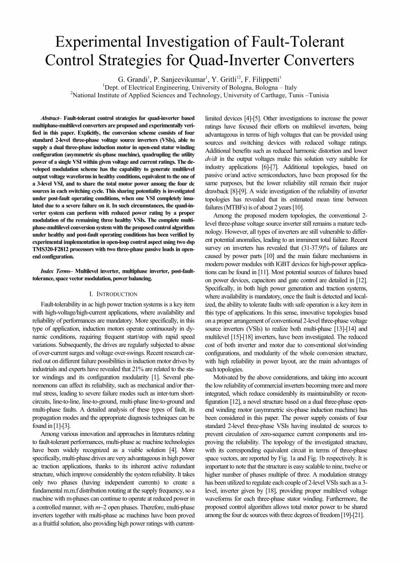
Motivated by the above considerations, and taking into account the low reliability of commercial inverters becoming more and more integrated, which reduce considerably its maintainability or recon-figuration [12], a novel structure based on a dual three-phase open-end winding motor (asymmetric six-phase induction machine) has been considered in this paper. The power supply consists of four standard 2-level three-phase VSIs having insulated dc sources to prevent circulation of zero-sequence current components and im-proving the reliability. The topology of the investigated structure, with its corresponding equivalent circuit in terms of three-phase space vectors, are reported by Fig. 1a and Fig. 1b respectively. It is important to note that the structure is easy scalable to nine, twelve or higher number of phases multiple of three. A modulation strategy has been utilized to regulate each couple of 2-level VSIs such as a 3-level, inverter given by [18], providing proper multilevel voltage waveforms for each three-phase stator winding. Furthermore, the proposed control algorithm allows total motor power to be shared among the four dc sources with three degrees of freedom [19]-[21].
In perspective view, the proposed contribution is de-voted to investigate inherent active redundancy of the used quad-inverter, under one, two or three failed inverters, to ensure system operability in the degraded modes given by [22]. In this paper, once the fault is diagnosed, the post-fault operating condition under one severe failed inverter is in-vestigated by experimental tests, to confirm the simulation results given in [23]. The resulting two degrees of freedom are exploited, if/when required, either to balance power sharing between the two three-phase motor windings (with minimization of power losses), or to balance the power sharing among the three remaining dc sources.
II. BASICS OF THE QUAD-INVERTER CONVERSION SCHEME Multiple space vectors are considered to represent the
variables of the whole six-phase system consisting of the dual three-phase machine supplied by four three-phase VSIs with insulated dc supplies. In particular, the asymmetric six-phase space vector transformations introduced in [13], [14] are considered.
In the case of a dual three-phase induction motor having sinusoidal distributed stator windings, the machine behavior can be described in terms of multiple space vectors by the following equations, in a stationary reference frame [14]:
11 1
SS S S
dv R i
dt
ϕ= + , 1 1 1 1 1S S S RL i M iϕ = + , (1)
11 10 R
R R m Rd
R i j pdt
ϕω ϕ= − + , 1 1 1 1 1R S R RM i L iϕ = + , (2)
55 5
SS S S
dv R i
dt
ϕ= + , 5 5S S SL iϕ = , (3)
1 1 13 S RT pM i j i= ⋅ , (4)
where p is the pole pairs number, ωm is the rotor angular speed, and the subscripts S and R denote stator and rotor quantities, respectively. It should be noted that the sinusoi-dal spatial distribution of the magnetic field in the air gap is mainly generated by the space vectors 1Si and 1Ri , whereas
5Si does not contribute to the air gap field. The total motor power P can be expressed by [21]:
( ) ( )[ ])2()2()2()1()1()1()2()1(
23 ivvivvPPP LHLH ⋅++⋅+=+= , (5)
being P(1) and P(2) the individual powers of the two three-phase stator windings {1} and {2} given by:
(1) (1) (1)
(2) (2) (2)
32
32
P v i
P v i
= ⋅
= ⋅
⎧⎪⎨⎪⎩
, (6)
and the stator winding voltages v(1) and v(2) can be written as the sum of voltages of the individual inverters “H” and “L” as:
(1) (1) (1)
(2) (2) (2)H L
H L
v v v
v v v
= +
= +
⎧⎪⎨⎪⎩
. (7)
The total power can be shared among the four dc sources of the quad-inverter system with three-degrees of freedom, expressed by the three coefficients ki , kv
(1) , and kv(2) [21].
The first coefficient ki concerns with current and power sharing between the two three-phase windings {1} and {2}:
(1)1
(2)1
212 (1 )
i S
i S
i k i
i k iα
=−= −
⎧⎪⎨⎪⎩
, (8)
(1) (1) (1)
(2) (2) (2) (1 )H L i
H L i
P P P k P
P P P k P
= + ≅
= + ≅ −
⎧⎪⎨⎪⎩
. (9)
The second kv(1) and third kv
(2) coefficients are related to the voltage and power sharing between the two inverters “H” and “L” which supply each three-phase winding:
( )(1) (1) (1)
(1) (1) (1)1H v
L v
v k v
v k v
=
= −
⎧⎪⎨⎪⎩
( )(2) (2) (2)
(2) (2) (2)1H v
L v
v k v
v k v
=
= −
⎧⎪⎨⎪⎩
, (10)
( )(1) (1) (1)
(1) (1) (1)1H v
L v
P k P
P k P
=
= −
⎧⎪⎨⎪⎩
( )(2) (2) (2)
(2) (2) (2)1H v
L v
P k P
P k P
=
= −
⎧⎪⎨⎪⎩
. (11)
Note that, to equally share the motor power among the four inverters, i.e., 25% of the total power for each dc source, all sharing coefficients ki, kv
(1), and kv(2) must be set
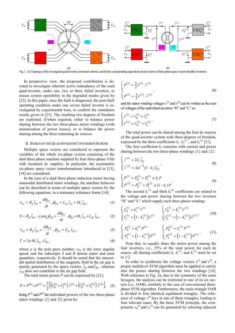
to 1/2. In order to synthesize the voltage vectors v(1) and v(2), a
proper multilevel SVM algorithm must be applied to satisfy also the power sharing between the two windings [18]. With reference to Fig. 2a, due to the symmetry of the outer hexagon, the analysis can be restricted to one of its six sec-tors (i.e., OAB), similarly to the case of conventional three-phase SVM algorithm. Furthermore, the main triangle OAB is divided in four identical equilateral triangles. The refer-ence of voltage v(1) lays in one of these triangles, leading to four relevant cases. By the basic SVM principle, the com-ponents vH
(1) and vL(1) can be generated by selecting adjacent
Vdc
Vdc Vdc
{1} {2}
Vdc30°
Vdc )1(Hv
)1(LvVdc
)1(i
)1(v
)2(Hv
)2(Lv
Vdc
)2(i
)2(v
Vdc
)1(HI
)1(LI
)2(HI
)2(LI
(2)VSIH
(1)VSIL
(1)VSIH
(2)VSIL
{2} {1}
(a) (b) Fig. 1. (a) Topology of the investigated quad-inverter conversion scheme, and (b) the corresponding equivalent circuit in terms of three-phase space vectors (healthy inverters).
vectors. The switch configurations corresponding to these vectors cannot be applied in an arbitrary sequence if proper multilevel voltage waveforms are desired, i.e., the voltage v(1) should be generated by using the nearest three vectors approach (NTV) [21]. For this purpose, the method intro-duced in [18] has been implemented. The same considera-tions are valuable for the voltage v(2).
III. THE PROPOSED POST-FAULT-TOLERANT STRATEGIES Integrated cooling technologies are widely employed in
commercial inverter applications for high power ac traction system. Advantages of such technologies are ease-of-use, miniaturization and compactness in traction systems. How-ever, the non-maintainability due to the compact packaging and the reduced thermal dissipation justifies the reduced re-liability of the inverters [8], [11], [12].
Independently to the technology adopted, the inverters are still mainly subjected to several failures due to:
dc-link electrolytic capacitor, dc bus voltage sensor, power semiconductor (either short- or open-circuit), control and driver circuits,
commonly known by their rapid propagation, leading to se-vere degrees of damage for the whole system.
For these reasons, once the fault is detected and local-ized in one among the four inverters, most of the times the concerned inverter can be considered as totally damaged and must be completely isolated. The failed inverter should be disconnected from both the motor and the dc source (bat-tery), e.g. using bypass switches. Then, the developed con-trol system is adapted in a manner that the ac motor drive machine still continues to operate in post-fault conditions.
Under the considered post-fault configuration, the pro-
posed control strategy allows continuity of operation, but with a reduced power range and loosing one degree of free-dom in the power sharing among the dc sources: from three degrees, under healthy conditions, to two degrees.
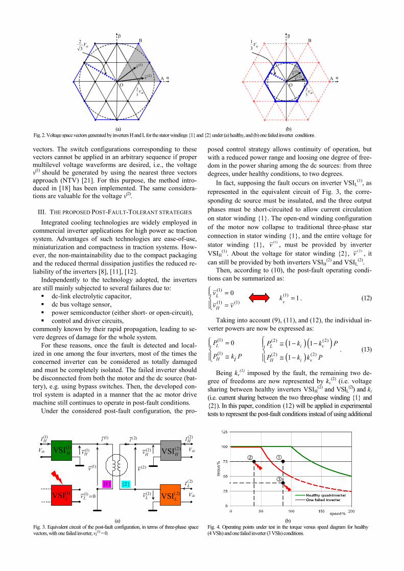
In fact, supposing the fault occurs on inverter VSIL(1), as
represented in the equivalent circuit of Fig. 3, the corre-sponding dc source must be insulated, and the three output phases must be short-circuited to allow current circulation on stator winding {1}. The open-end winding configuration of the motor now collapse to traditional three-phase star connection in stator winding {1}, and the entire voltage for stator winding {1}, (1)v , must be provided by inverter VSIH
(1). About the voltage for stator winding {2}, ( 2)v , it can still be provided by both inverters VSIH
(2) and VSIL(2).
Then, according to (10), the post-fault operating condi-tions can be summarized as:
(1)
(1) (1)
0L
H
v
v v
=
=
⎧⎪⎨⎪⎩
(1) 1v
k = . (12)
Taking into account (9), (11), and (12), the individual in-verter powers are now be expressed as:
(1)
(1)
0L
H
P
P k Pi
=
≅
⎧⎪⎨⎪⎩
( ) ( )( )
(2) (2)
(2) (2)
1 1
1
L i v
H i v
P k k P
P k k P
≅ − −
≅ −
⎧⎪⎨⎪⎩
. (13)
Being kv(1) imposed by the fault, the remaining two de-
gree of freedoms are now represented by kv(2) (i.e. voltage
sharing between healthy inverters VSIH(2) and VSIL
(2)) and ki (i.e. current sharing between the two three-phase winding {1} and {2}). In this paper, condition (12) will be applied in experimental tests to represent the post-fault conditions instead of using additional
dcV32
OA
B
α
β
)1(v
)2(v
dcV3
2
dcV32
O A
B
α
β
)1(v )2(v
dcV31
(a) (b) Fig. 2. Voltage space vectors generated by inverters H and L for the stator windings {1} and {2} under (a) healthy, and (b) one failed inverter conditions.
Vdc )1(Hv
0)1( =Lv
)1(i
)1(v
)2(Hv Vdc
)2(i
)2(v
Vdc
)1(HI )2(
HI
)2(LI
( 2)VSIL
(2)VSIH
)2(Lv
(1)VSIH
(1)VSIL
{1} {2}
(a) (b) Fig. 3. Equivalent circuit of the post-fault configuration, in terms of three-phase space vectors, with one failed inverter, vL
(1) = 0. Fig. 4. Operating points under test in the torque versus speed diagram for healthy(4 VSIs) and one failed inverter (3 VSIs) conditions.
bypass switches for creating star connection on the faulty inverter and complete insulation and for current circulation. The first rele-vant consequence of the fault in one inverter is that the maximum output voltage for one of the two three-phase stator windings is halved. Then, since the two stator wind-ings share the same magnetic circuit and have the same in-duced e.m.f., the maximum voltage of the other stator winding is halved as well, from 2/√3Vdc to 1/√3Vdc, as em-phasized in Fig. 2b, leading to a 50% reduction of the whole maximum motor power. The different working conditions are summarized in Fig. 4, with reference to the torque ver-sus speed characteristics in healthy (green line) and faulty (red line) operating conditions.
As an example, the operating point can be imple-mented only in healthy conditions, whereas the operating points and can be implemented also in post-fault con-ditions (the last one with a flux weakening to reduce the re-quired stator winding voltage).
Different strategies can be introduced to realize the post-fault operating conditions, with the remaining three healthy VSIs. In this paper will be considered the two relevant cases of minimization of power losses and symmetrical power sharing among the three healthy VSIs (i.e., among the cor-responding three dc sources).
A. Balanced power sharing between the two three-phase stator motor windings and minimization of power losses
As known, a balanced current sharing between the two three-phase windings leads to minimum stator copper losses. This can be simply implemented in post-fault condi-tions by setting ki = ½, with arbitrary voltage sharing coef-ficient kv
(2) to synthesize v(2). Although the usage of both VSIH
(2) and VSIL(2) allows an active redundancy, it is not
optimal from the point of view of the inverter losses, in-volving two inverters when the desired output voltage could be synthesized with just one of them.
For this reason, the provision of a passive redundancy with one inverter for the winding {2} still considerably im-prove the reliability of the post-fault configuration but it re-duces the whole converter losses. In this case, inverter VSIH
(1) can operates just with inverter VSIH(2), whereas the
output voltage of inverter VSIL(2) can be set to zero, or vice
versa, leading to exactly the same operating performances of the motor. The open-end windings configuration of the motor now collapse to traditional three-phase star connec-tions for both stator windings. Voltage and power equa-tions, (10), (9) and (11), in addition to the fault condition (12), can now be summarized as:
(2)
(2) (2)
0L
H
v
v v
=
=
⎧⎪⎨⎪⎩
(2) 1v
k = , (14)
(1)
(1)
012
L
H
P
P P
=
=
⎧⎪⎨⎪⎩
(2)
(2)
012
L
H
P
P P
=
=
⎧⎪⎨⎪⎩
12ik = . (15)
B. Balanced power sharing among the three healthy VSIs As a further step in this post-fault investigation, the point
of interest is now to share the total motor power symmetri-cally among the three healthy inverters, i.e., among the three remaining dc sources. This behavior is recommended
for battery supplied traction systems, in which the balanced charge status of batteries can be considered as a crucial is-sue. In order to implement a balanced power sharing among the three dc power supplies, an unbalanced power sharing between the two three-phase windings {1} and {2} must be introduced. In particular, one third of the total motor power must be supplied by each VSI. According to (9)-(13), the following voltage and power equations can be written:
(2) (2)
(2) (2)
1212
L
H
v v
v v
=
=
⎧⎪⎨⎪⎩
(2) 12vk = , (16)
(1)
(1)
013
L
H
P
P P
=
=
⎧⎪⎨⎪⎩
(2)
(2)
1313
L
H
P P
P P
=
=
⎧⎪⎨⎪⎩
13ik = . (17)
In the next section, simplified experimental tests under healthy and post-fault operating conditions are presented and discussed with reference both balanced and unbalanced power sharing approaches.
IV. EXPERIMENTAL RESULTS
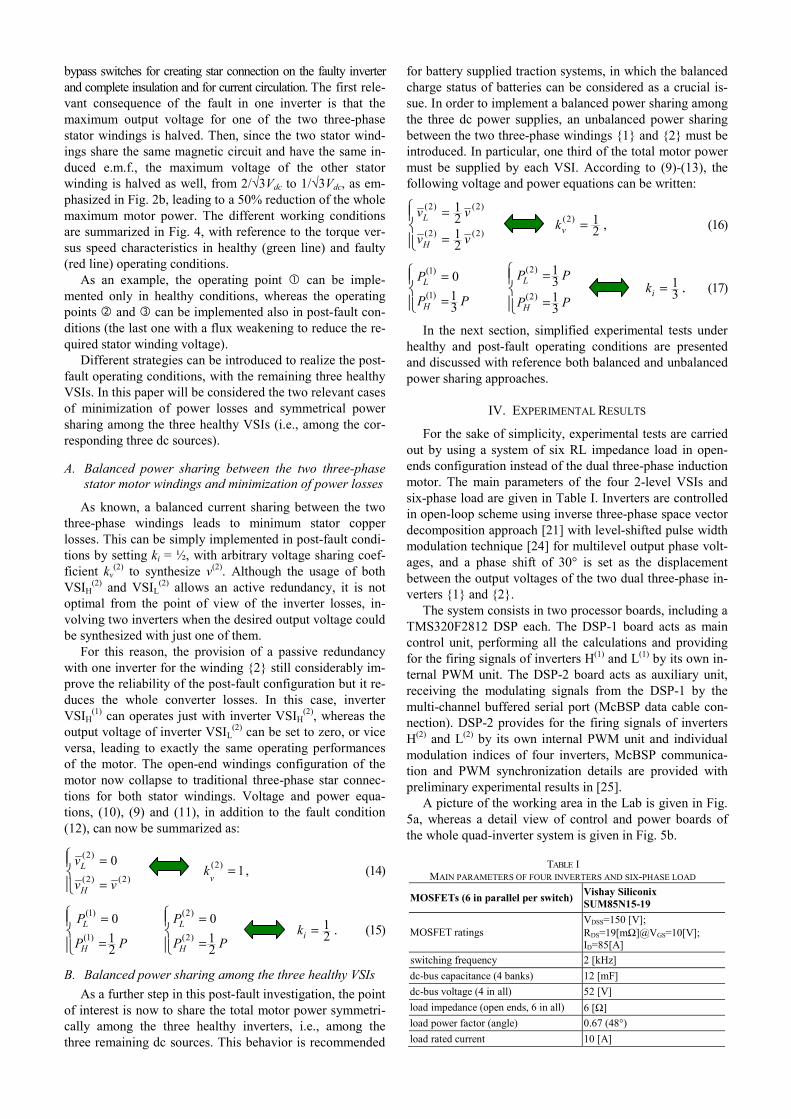
For the sake of simplicity, experimental tests are carried out by using a system of six RL impedance load in open-ends configuration instead of the dual three-phase induction motor. The main parameters of the four 2-level VSIs and six-phase load are given in Table I. Inverters are controlled in open-loop scheme using inverse three-phase space vector decomposition approach [21] with level-shifted pulse width modulation technique [24] for multilevel output phase volt-ages, and a phase shift of 30° is set as the displacement between the output voltages of the two dual three-phase in-verters {1} and {2}.
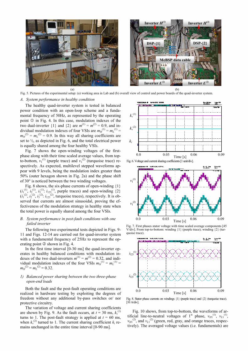
The system consists in two processor boards, including a TMS320F2812 DSP each. The DSP-1 board acts as main control unit, performing all the calculations and providing for the firing signals of inverters H(1) and L(1) by its own in-ternal PWM unit. The DSP-2 board acts as auxiliary unit, receiving the modulating signals from the DSP-1 by the multi-channel buffered serial port (McBSP data cable con-nection). DSP-2 provides for the firing signals of inverters H(2) and L(2) by its own internal PWM unit and individual modulation indices of four inverters, McBSP communica-tion and PWM synchronization details are provided with preliminary experimental results in [25].
A picture of the working area in the Lab is given in Fig. 5a, whereas a detail view of control and power boards of the whole quad-inverter system is given in Fig. 5b.
TABLE I MAIN PARAMETERS OF FOUR INVERTERS AND SIX-PHASE LOAD
MOSFETs (6 in parallel per switch) Vishay Siliconix SUM85N15-19
MOSFET ratings VDSS=150 [V]; RDS=19[mΩ]@VGS=10[V]; ID=85[A]
switching frequency 2 [kHz] dc-bus capacitance (4 banks) 12 [mF] dc-bus voltage (4 in all) 52 [V] load impedance (open ends, 6 in all) 6 [Ω] load power factor (angle) 0.67 (48°) load rated current 10 [A]
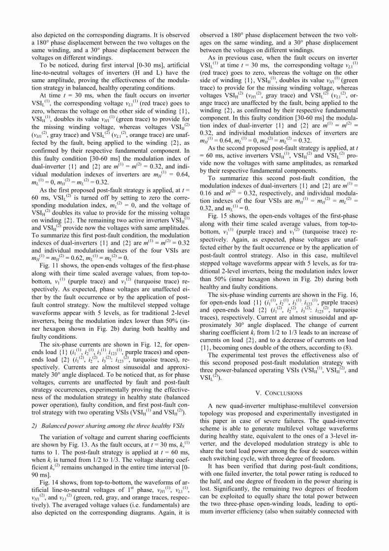
A. System performance in healthy condition The healthy quad-inverter system is tested in balanced
power condition with an open-loop scheme and a funda-mental frequency of 50Hz, as represented by the operating point in Fig. 4. In this case, modulation indexes of the two dual-inverter {1} and {2} are m(1) = m(2) = 0.9, and in-dividual modulation indexes of four VSIs are mH
(1) = mL(1) =
mH(2) = mL
(2) = 0.9. In this way all sharing coefficients are set to ½, as depicted in Fig. 6, and the total electrical power is equally shared among the four healthy VSIs.
Fig. 7 shows the open-winding voltages of the first-phase along with their time scaled average values, from top-to-bottom, v1
(1) (purple trace) and v1(2) (turquoise trace) re-
spectively. As expected, multilevel stepped waveforms ap-pear with 9 levels, being the modulation index greater than 50% (outer hexagon shown in Fig. 2a) and the phase shift of 30° is noticed between the two winding voltages.
Fig. 8 shows, the six-phase currents of open-winding {1} (i1
(1), i2(1), i3
(1): i123(1), purple traces) and open-winding {2}
(i1(2), i2
(2), i3(2): i123
(2), turquoise traces), respectively. It is ob-served that currents are almost sinusoidal, proving the ef-fectiveness of the modulation strategy in healthy state when the total power is equally shared among the four VSIs.
B. System performance in post-fault conditions with one failed inverter
The following two experimental tests depicted in Figs. 9-11 and Figs. 12-14 are carried out for quad-inverter system with a fundamental frequency of 25Hz to represent the op-erating point shown in Fig. 4.
In the first time interval [0-30 ms] the quad-inverter op-erates in healthy balanced conditions with modulation in-dexes of the two dual-inverters m(1) = m(2) = 0.32, and indi-vidual modulation indexes of the four VSIs mH
(1) = mL(1) =
mH(2) = mL
(2) = 0.32.
1) Balanced power sharing between the two three-phase open-end loads
Both the fault and the post-fault operating conditions are realized in hardware testing by exploiting the degrees of freedom without any additional by-pass switches or/ nor protective circuitry.
The variation of voltage and current sharing coefficients are shown by Fig. 9. As the fault occurs, at t = 30 ms, kv
(1) turns to 1. The post-fault strategy is applied at t = 60 ms, when kv
(2) turned to 1. The current sharing coefficient ki re-mains unchanged in the entire time interval [0-90 ms].
Fig. 10 shows, from top-to-bottom, the waveforms of ar-tificial line-to-neutral voltages of 1st phase, vH1
(1), vL1(1),
vH1(2), and vL1
(2) (green, red, gray, and orange traces, respec-tively). The averaged voltage values (i.e. fundamentals) are
Inverter H(1) Inverter H(2)
Inverter L(2) Inverter L(2)
DSP-{1} DSP-{2}
McBSP data cable
(a) (b) Fig. 5. Pictures of the experimental setup: (a) working area in Lab and (b) overall view of control and power boards of the quad-inverter system.
Time [s] 0.0 0.03 0.06 0.09
kv(1)
kv(2)
ki
Fig. 6. Voltage and current sharing coefficients [1 unit/div].
v1(1)
v1(2)
Time [s] 0.0 0.03 0.06 0.09
Fig. 7. First phases stator voltage with time scaled average components [45 V/div]. From top-to-bottom: winding {1} (purple trace); winding {2} (tur-quoise trace).
Time [s] 0.0 0.03 0.06 0.09
i123(2)
i123(1)
Fig. 8. Stator phase currents on windings {1} (purple trace) and {2} (turquoise trace). [10 A/div].
also depicted on the corresponding diagrams. It is observed a 180° phase displacement between the two voltages on the same winding, and a 30° phase displacement between the voltages on different windings.
To be noticed, during first interval [0-30 ms], artificial line-to-neutral voltages of inverters (H and L) have the same amplitude, proving the effectiveness of the modula-tion strategy in balanced, healthy operating conditions.
At time t = 30 ms, when the fault occurs on inverter VSIL
(1), the corresponding voltage vL1(1) (red trace) goes to
zero, whereas the voltage on the other side of winding {1}, VSIH
(1), doubles its value vH1(1) (green trace) to provide for
the missing winding voltage, whereas voltages VSIH(2)
(vH1(2), gray trace) and VSIL
(2) (vL1(2), orange trace) are unaf-
fected by the fault, being applied to the winding {2}, as confirmed by their respective fundamental component. In this faulty condition [30-60 ms] the modulation index of dual-inverter {1} and {2} are m(1) = m(2) = 0.32, and indi-vidual modulation indexes of inverters are mH
(1) = 0.64, mL
(1) = 0, mH(2) = mL
(2) = 0.32. As the first proposed post-fault strategy is applied, at t =
60 ms, VSIL(2) is turned off by setting to zero the corre-
sponding modulation index, mL(2) = 0, and the voltage of
VSIH(2) doubles its value to provide for the missing voltage
on winding {2}. The remaining two active inverters VSIH(1)
and VSIH(2) provide now the voltages with same amplitudes.
To summarize this first post-fault condition, the modulation indexes of dual-inverters {1} and {2} are m(1) = m(2) = 0.32 and individual modulation indexes of the four VSIs are mH
(1) = mH(2) = 0.62, mL
(1) = mL(2) = 0.
Fig. 11 shows, the open-ends voltages of the first-phase along with their time scaled average values, from top-to-bottom, v1
(1) (purple trace) and v1(2) (turquoise trace) re-
spectively. As expected, phase voltages are unaffected ei-ther by the fault occurrence or by the application of post-fault control strategy. Now the multilevel stepped voltage waveforms appear with 5 levels, as for traditional 2-level inverters, being the modulation index lower than 50% (in-ner hexagon shown in Fig. 2b) during both healthy and faulty conditions.
The six-phase currents are shown in Fig. 12, for open-ends load {1} (i1
(1), i2(1), i3
(1): i123
(1), purple traces) and open-ends load {2} (i1
(2), i2(2), i3
(2): i123(2), turquoise traces), re-
spectively. Currents are almost sinusoidal and approxi-mately 30° angle displaced. To be noticed that, as for phase voltages, currents are unaffected by fault and post-fault strategy occurrences, experimentally proving the effective-ness of the modulation strategy in healthy state (balanced power operation), faulty condition, and first post-fault con-trol strategy with two operating VSIs (VSIH
(1) and VSIH(2)).
2) Balanced power sharing among the three healthy VSIs
The variation of voltage and current sharing coefficients are shown by Fig. 13. As the fault occurs, at t = 30 ms, kv
(1) turns to 1. The post-fault strategy is applied at t = 60 ms, when ki is turned from 1/2 to 1/3. The voltage sharing coef-ficient kv
(2) remains unchanged in the entire time interval [0-90 ms].
Fig. 14 shows, from top-to-bottom, the waveforms of ar-tificial line-to-neutral voltages of 1st phase, vH1
(1), vL1(1),
vH1(2), and vL1
(2) (green, red, gray, and orange traces, respec-tively). The averaged voltage values (i.e. fundamentals) are also depicted on the corresponding diagrams. Again, it is
observed a 180° phase displacement between the two volt-ages on the same winding, and a 30° phase displacement between the voltages on different windings.
As in previous case, when the fault occurs on inverter VSIL
(1) at time t = 30 ms, the corresponding voltage vL1(1)
(red trace) goes to zero, whereas the voltage on the other side of winding {1}, VSIH
(1), doubles its value vH1(1) (green
trace) to provide for the missing winding voltage, whereas voltages VSIH
(2) (vH1(2), gray trace) and VSIL
(2) (vL1(2), or-
ange trace) are unaffected by the fault, being applied to the winding {2}, as confirmed by their respective fundamental component. In this faulty condition [30-60 ms] the modula-tion index of dual-inverter {1} and {2} are m(1) = m(2) = 0.32, and individual modulation indexes of inverters are mH
(1) = 0.64, mL(1) = 0, mH
(2) = mL(2) = 0.32.
As the second proposed post-fault strategy is applied, at t = 60 ms, active inverters VSIH
(1), VSIH(2) and VSIL
(2) pro-vide now the voltages with same amplitudes, as remarked by their respective fundamental components.
To summarize this second post-fault condition, the modulation indexes of dual-inverters {1} and {2} are m(1) = 0.16 and m(2) = 0.32, respectively, and individual modula-tion indexes of the four VSIs are mH
(1) = mH(2) = mL
(2) = 0.32, and mL
(1) = 0. Fig. 15 shows, the open-ends voltages of the first-phase
along with their time scaled average values, from top-to-bottom, v1
(1) (purple trace) and v1(2) (turquoise trace) re-
spectively. Again, as expected, phase voltages are unaf-fected either by the fault occurrence or by the application of post-fault control strategy. Also in this case, multilevel stepped voltage waveforms appear with 5 levels, as for tra-ditional 2-level inverters, being the modulation index lower than 50% (inner hexagon shown in Fig. 2b) during both healthy and faulty conditions.
The six-phase winding currents are shown in the Fig. 16, for open-ends load {1} (i1
(1), i2(1), i3
(1): i123
(1), purple traces) and open-ends load {2} (i1
(2), i2(2), i3
(2): i123(2), turquoise
traces), respectively. Current are almost sinusoidal and ap-proximately 30° angle displaced. The change of current sharing coefficient ki from 1/2 to 1/3 leads to an increase of currents on load {2}, and to a decrease of currents on load {1}, becoming ones double of the others, according to (8).
The experimental test proves the effectiveness also of this second proposed post-fault modulation strategy with three power-balanced operating VSIs (VSIH
(1), VSIH(2), and
VSIL(2)).
V. CONCLUSIONS
A new quad-inverter multiphase-multilevel conversion topology was proposed and experimentally investigated in this paper in case of severe failures. The quad-inverter scheme is able to generate multilevel voltage waveforms during healthy state, equivalent to the ones of a 3-level in-verter, and the developed modulation strategy is able to share the total load power among the four dc sources within each switching cycle, with three degree of freedom.
It has been verified that during post-fault conditions, with one failed inverter, the total power rating is reduced to the half, and one degree of freedom in the power sharing is lost. Significantly, the remaining two degrees of freedom can be exploited to equally share the total power between the two three-phase open-winding loads, leading to opti-mum inverter efficiency (also when suitably connected with

motor), or among the three remaining dc sources, leading to a balanced charge status in case of battery power supplies.
The hardware implementation has been carried out by using two DSP TMS320F2812 boards, each one controlling in open-loop mode a dual three-phase inverter, with a six-phase open-ends passive load.
Experimental tests show a good agreement with all theo-retical developments, proving that the proposed power multiphase-multilevel conversion scheme is suitable to drive a dual three-phase induction motor with open-end stator winding configuration under healthy and post-fault conditions.
Time [s] 0.0 0.03 0.06 0.09
kv(1)
kv(2)
ki
Fig. 9. Voltage and current sharing coefficients [1 unit/div].
Time [s] 0.0 0.03 0.06 0.09
vH1(1)
v\L1(1)
vL1(2)
vH1(2)
Fig. 10. Artificial line-to-neutral voltage (first phases) with their time scaled average components [45 V/div]. From top-to-bottom: dual-inverter {1}: H (green) and L (red) traces, dual-inverter {2}: H (gray) and L (orange) traces.
v1(1)
v1(2)
Time [s] 0.0 0.03 0.06 0.09
Fig. 11. First phases stator voltage with time scaled average components [45 V/div]. From top-to-bottom: winding {1} (purple trace); winding {2} (turquoise trace).
Time [s] 0.0 0.03 0.06 0.09
i123(2)
i123(1)
Fig. 12. Stator phase currents on windings {1} (purple trace) and {2} (turquoise trace). [2 A/div].
Time [s] 0.0 0.03 0.06 0.09
kv(1)
kv(2)
ki
Fig. 13. Voltage and current sharing coefficients [1 unit/div].
Time [s] 0.0 0.03 0.06 0.09
vH1(1)
v\L1(1)
vL1(2)
vH1(2)
Fig. 14. Artificial line-to-neutral voltage (first phases) with their time scaled average components [45 V/div]. From top-to-bottom: dual-inverter {1}: H (green) and L (red) traces, dual-inverter {2}: H (gray) and L (orange) traces.
v1(1)
v1(2)
Time [s] 0.0 0.03 0.06 0.09
Fig. 15. First phases stator voltage with time scaled average components [45 V/div]. From top-to-bottom: winding {1} (purple trace); winding {2} (turquoise trace).
Time [s] 0.0 0.03 0.06 0.09
i123(2)
i123(1)
Fig. 16. Stator phase currents on windings {1} (purple trace) and {2} (turquoise trace). [2 A/div].
VI. REFERENCES [1] A.H. Bonnett, C. Yung, "Increased efficiency versus increased
reliability,” in Conf. Proc. IEEE Ind. App. Mag., vol. 14, no. 1, Jan.–Feb. 2008.
[2] A. Siddique, G. S. Yadava, B. Singh, "A review of stator fault monitoring techniques of induction motors,” IEEE Tran. on Ener. Conv., vol. 20, no. 1, March 2005.
[3] A. Bellini, F. Filippetti, C. Tassoni, G. A. Capolino, "Advances in diagnostic techniques for induction machines,” IEEE Trans. on Ind. Electron., vol.55, no. 12, Dec. 2008.
[4] E. Levi, “Multiphase electric machines for variable-speed applications,” IEEE Trans. on Ind. Appl., vol. 55, no. 5, pp. 1893–1909, May 2008.
[5] G. Grandi, G. Serra, A. Tani, “General analysis of multiphase systems based on space vector approach,” in Proc. Inter. Power Electron., and Motion Control Conf., EPE–PEMC’06, Portoroz, Slo-venia, pp. 834–840, 30 Aug.–1 Sep. 2006.
[6] J. Rodriguez, S. Bernet, Bin Wu, J.O. Pontt, S. Kouro, “Multilevel voltage-source-converter topologies for industrial medium-voltage drives,” IEEE Trans. on Ind. Electron., vol. 54, no. 6, pp. 2930–2945, Dec. 2007.
[7] L.G. Franquelo, J. Rodriguez, J.I. Leon, S. Kouro, R. Portillo, M. M. Prats, “The age of multilevel converters arrives,” in Proc. IEEE Ind. Electron., Magazine, vol. 2, no. 2, pp. 28–39, June 2008.
[8] S. Bolognani, M. Zordan, M. Zigliotto, "Experimental fault-tolerant control of a PMSM drive,” IEEE Trans. on Ind. Electron., vol. 47, no. 5, pp. 1134–1141, Oct. 2000.
[9] R. L. de A. Ribeiro, C. B. Jacobina, E. R. C. da Silva, A. M. N. Lima, "Fault-tolerant voltage-fed PWM inverter ac motor drive systems,” IEEE Trans. on Ind. Electron., vol. 51, no. 2, pp. 439–446, Apr. 2004.
[10] A.L. Julian, G. Oriti, "A comparison of redundant inverter topologies to improve voltage source inverter reliability,” IEEE Trans. on Ind. Appl., vol. 43, pp. 1371–1378, 2007.
[11] S. Yang, A. Bryant, P. Mawby, D. Xiang, Li Ran, P. Tavner, "An industry-based survey of reliability in power electronic converters,” IEEE Trans. on Ind. Electron., vol. 47, no. 3, pp. 1441–1451, May–June 2011.
[12] S. Yang, D. Xiang, A. Bryant, P. Mawby, Li Ran, P. Tavner, "Condition monitoring for device reliability in power electronic converters: A review,” IEEE Trans. on Power Electron., vol. 25, no. 11, pp. 2734–2752, Nov. 2010.
[13] Y. Zhao, T.A. Lipo, “Space vector PWM control of dual three-phase induction machine using vector space decomposition,” IEEE Trans. on Ind. Appl., vol. 31, no. 5, pp. 1100–1109, Sept.–Oct. 1995.
[14] G. Grandi, A. Tani, G. Serra, “Space vector modulation of six-phase VSI based on three-phase decomposition,” in Conf. Proc. IEEE 19th Symposium on Power Electron., Electrical Drives etc., SPEEDAM’08, Taormina (IT), pp. 674–679, 11–13 June 2008.
[15] Y. Kawabata, M. Nasu, T. Nomoto, E.C. Ejiogu, T.Kawabata, “High-efficiency and low acoustic noise drive system using open-winding AC motor and two space-vector-modulated inverters,” IEEE Trans. on Ind. Electron., vol. 49, no. 4, pp. 783–789, Aug. 2002.
[16] J. Kim, J. Jung, K. Nam, “Dual-inverter control strategy for high-speed operation of EV induction motors,” IEEE Trans. on Ind. Electron., vol. 51, no. 2, pp. 312–320, Apr. 2004.
[17] R. Kanchan, P. Tekwani, K. Gopakumar, “Three-level inverter scheme with common mode voltage elimination and dc link capacitor voltage balancing for an open-end winding induction motor drive,” IEEE Trans. on Power Electron., vol. 21, no. 6, pp. 1676–683, Nov. 2006.
[18] G. Grandi, C. Rossi, A. Lega, D. Casadei, “Multilevel operation and input power balancing for a dual two-level inverter with insulated dc sources,” IEEE Trans. on Ind. Appl., vol. 44, no. 6, pp. 1815–1824, Nov.–Dec. 2008.
[19] R. Bojoi, A. Tenconi, F. Farina, F. Profumo, “Dual-source fed multi-phase induction motor drive for fuel cell vehicles: Topology and control,” in Proc. of 36th Power Electron., Specialists Conf., PESC’05, Recife, Brazil, pp. 2676–2683, June 2005.
[20] D.G. Holmes, T.A. Lipo, “Pulse width modulation for power con-verters: Principles and practice”, IEEE Press-John Wiley, pp. 467–469, 2003.
[21] G. Grandi, A. Tani, P. Sanjeevikumar, D. Ostojic, “Multi-phase multi-level ac motor drive based on four three-phase two-level inverters,” in Conf. Proc. IEEE 20th Symposium on Power Electron., Electrical Drives etc., SPEEDAM’10, Pisa (IT), pp. 1768–1775, June 2010.
[22] G. Grandi, Y. Gritli, F. Filipetti, C. Rossi, “Fault-tolerant operating analysis of a quad-inverter multiphase multilevel ac motor drive,” in Conf. Proc. IEEE-SDEMPED’11, Bologna (IT), pp. 126–132, Sept. 2011.
[23] G. Grandi, P. Sanjeevikumar, Y. Gritli, F. Filippetti, “Fault-tolerant control strategies for quad-inverter induction motor drives with one failed inverter”, in Proc. 20th Intl. Conf. on Electrical Machines, ICEM’12, Marseille (F), 2–5 Sept., 2012.
[24] G. Grandi, D. Ostojic, “Dual inverter space vector modulation with power balancing capability”, in Proc. IEEE Region 8 Conf., EUROCON’09, St. Petersburg (RUS), pp. 721–728, 18–23 May 2009.
[25] G. Grandi, P. Sanjeevikumar, D. Casadei, “Preliminary hardware implementation of a six-phase quad-inverter induction motor drive,” in Proc. European Power Electron., and Appl., Conf., EPE’11, Birmingham (UK), pp. 1–9, 30 Aug.–1 Sept. 2011.