experimental investigation of plastic collapse of ... · experimental investigation of plastic...
TRANSCRIPT

Experimental investigation of plastic collapse of aluminium extrusions in biaxial bending
G. Belingardi & L. Peroni Department of Mechanics, Politecnico di Torino, Italy
Abstract
In this work some results obtained with an experimental investigation of the bending collapse problems of thin-walled beams are reported. The test equipment, specifically made to execute biaxial bending tests, is briefly described. A series of tests was made on thin-walled aluminium structural components, with square and rectangular sections. The aim of these experimental tests is the analysis of the beam behaviour in the collapse phase (after global buckling), in plane and biaxial loading conditions. The behaviour was analyzed under two points of view: a global one, with the determination of the structural response and the comparison with the theoretical and numerical models, and a local one, through the study of the dynamic of the plastic hinge mechanism. Keywords: biaxial bending, thin walled beam, plastic collapse.
1 Introduction
The plastic bending collapse constitutes the more frequent modality of yielding in thin wall tubular members subjected to dynamic loading conditions in vehicular and mechanical structures. The main reason of such behaviour comes from the smaller demand of specific energy that characterises this modality of collapse with respect to the axial folding one. The mechanisms of bending collapse, widely analysed in the scientific literature, presuppose that the collapse develops in a pure plane modality, in which the bending moment acts about one of the two main axis of inertia of the section. The structural members of the vehicle frame are designed in order to dissipate the vehicle kinetic energy in accident case and are generally submitted, in the complex dynamic motion of the impact, to loads of combined type, deriving
Structures Under Shock and Impact VIII, N. Jones & C. A. Brebbia (Editors)© 2004 WIT Press, www.witpress.com, ISBN 1-85312-706-XStructures Under Shock and Impact VIII, N. Jones & C. A. Brebbia (Editors)© 2004 WIT Press, www.witpress.com, ISBN 1-85312-706-X

directly from the action of external forces or, indirectly, from the effect of inner loads; a frontal collision with partial overlap or a rollover are examples of oblique load situation during a collision event. In this perspective it is of interest to analyse the behaviour of thin walled boxed beams submitted to biaxial bending i.e. collapse under the action of bending about a non-principal axis. In case of biaxial bending the phenomenon is not sufficiently clear: the localized zone of the tube where the most part of the phenomenon takes place cannot be assimilated to a rotational joint with a certain resistant moment M function of the rotation angle θ (how it could be done in case of the uniaxial bending). In plastic field, as already in elastic field, the neutral axis and the bending moment vector are not parallel; therefore a number of parameters is necessary for the characterisation of the phenomenon greater than the two ones (M and θ) sufficient in case of uniaxial bending.
Figure 1: Moment and deflection axes in biaxial bending.
Considering a thin walled beam (fig. 1) with rectangular cross section: a and b are the dimensions of the two sides measured on the average plan of the walls and t is the thickness of the wall; the length of the beam is L. Suppose that the beam is opportunely loaded to cause the inflection about a generic direction not coinciding with one of the two principal axes of inertia of the section; w (weak) and s (strong) are the two central axes of inertia of the section, z the longitudinal axis and x-y is a second reference system, generically rotated of an angle α respect to the w-s system, used to identify the orientation of the section in the space. Because the arbitrariness of the loading conditions, the resistant moment vector M, the neutral axis (N.A.) and therefore the bending plane B.P. perpendicular to the last one, are not necessarily parallel to any of the directions identified by the reference systems w-s and x-y. To identify the problem it is necessary to introduce the deviation angle (β) which gives the orientation of the moment vector with respect to the barycentric axis parallel to the N.A. and the (γ) angle (fig. 1) which identifies the N.A. orientation. In a generic bending loading condition the vector moment shows components respect both the principal section axis (Mw e Ms) and the axis parallel to the N.A. and the B.P. (MNA e MBP). In the case in which the constancy of the direction of the inflection plane is imposed, a constant bending plane biaxial loading condition is obtained
Structures Under Shock and Impact VIII, N. Jones & C. A. Brebbia (Editors)© 2004 WIT Press, www.witpress.com, ISBN 1-85312-706-XStructures Under Shock and Impact VIII, N. Jones & C. A. Brebbia (Editors)© 2004 WIT Press, www.witpress.com, ISBN 1-85312-706-X
338 Structures Under Shock and Impact VIII

(deflection axis fixed, moment axis free); vice versa, with the imposition of the direction of the bending moment, a biaxial loading condition with constant moment direction (deflection axis free, moment axis fixed) is obtained.
2 Test equipment
Starting from the exam of the techniques of experimental investigation used in previous works found in the literature [2-6], a proper test rig was designed and built at the Experimental Mechanics Laboratory of the 2nd Engineering Faculty of the Politecnico di Torino, in order to perform quasi static experimental bending tests (uniaxial and biaxial) on thin walled beams.
Pneumatic jack
Load lever
Thin- walled beam
B
H A
C
Plastic hinge
Z
Y
Camping device
Load links
Load link 1
Load link 2
Load lever
Pneumatic jack
Plastic hinge
extrusion
Camping device
BP
B C
A H
C1 C1
C2 C2
z y y
x
Load link 1
Load link 2
Figure 2: Test rig. The test rig loading system is represented in figure 2. The load lever-load links-thin walled beam system constitutes an articulate parallelogram kinematics’ mechanism; in such way the load applied in the point B (barycentre of the beam free edge) always maintains the same direction (parallel to the global rig y axis), for every angle of rotation of the load lever. The load lever is moved by a pneumatic jack. To ensure that the movement of the articulate parallelogram remains in the initial plane (ACBH), the edge B of the thin walled beam is connected to the load lever with two load links disposed symmetrically respect to the bending plane, with a certain opening angle (ψ). The structure C1BC2 constitutes a rigid triangle which forces the point B on the deflection plane B.P. (fig. 2). The introduction of a load cell in both the two load links allows measuring the load applied to the thin walled beam and its direction in the xy plane. A wire displacement sensor connected to the free edge of the beam allows measuring the displacement of the loading point. From these measures it is possible to determine, on the basis of simple geometrical relations, the instantaneous values of the bending moment (modulus and direction) and of the angle of rotation of the plastic hinge. The beam is clamped by means of a special clamping system (fig. 2) which assures a complete clamp constraint. The adopted solution consists in an internal block and a system of outside tightening plates: the locking of the block in any angular
Structures Under Shock and Impact VIII, N. Jones & C. A. Brebbia (Editors)© 2004 WIT Press, www.witpress.com, ISBN 1-85312-706-XStructures Under Shock and Impact VIII, N. Jones & C. A. Brebbia (Editors)© 2004 WIT Press, www.witpress.com, ISBN 1-85312-706-X
Structures Under Shock and Impact VIII 339
position (of rotation about its axis) allows to execute biaxial bending tests (rotation angle of the block ≡ γ). The system is connected to a PC equipped with an acquisition board (National Instruments DAQPAD 6070E); the PC sends to the machine control unit the command signals for the control of the valves for the pneumatic cylinder movement. The NI board acquires the signals coming from the transducers.
3 Experimental tests
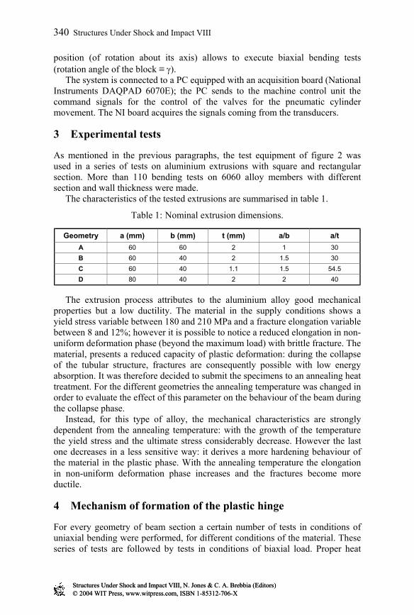
As mentioned in the previous paragraphs, the test equipment of figure 2 was used in a series of tests on aluminium extrusions with square and rectangular section. More than 110 bending tests on 6060 alloy members with different section and wall thickness were made. The characteristics of the tested extrusions are summarised in table 1.
Table 1: Nominal extrusion dimensions.
Geometry a (mm) b (mm) t (mm) a/b a/t A 60 60 2 1 30 B 60 40 2 1.5 30 C 60 40 1.1 1.5 54.5 D 80 40 2 2 40
The extrusion process attributes to the aluminium alloy good mechanical properties but a low ductility. The material in the supply conditions shows a yield stress variable between 180 and 210 MPa and a fracture elongation variable between 8 and 12%; however it is possible to notice a reduced elongation in non-uniform deformation phase (beyond the maximum load) with brittle fracture. The material, presents a reduced capacity of plastic deformation: during the collapse of the tubular structure, fractures are consequently possible with low energy absorption. It was therefore decided to submit the specimens to an annealing heat treatment. For the different geometries the annealing temperature was changed in order to evaluate the effect of this parameter on the behaviour of the beam during the collapse phase. Instead, for this type of alloy, the mechanical characteristics are strongly dependent from the annealing temperature: with the growth of the temperature the yield stress and the ultimate stress considerably decrease. However the last one decreases in a less sensitive way: it derives a more hardening behaviour of the material in the plastic phase. With the annealing temperature the elongation in non-uniform deformation phase increases and the fractures become more ductile.
4 Mechanism of formation of the plastic hinge
For every geometry of beam section a certain number of tests in conditions of uniaxial bending were performed, for different conditions of the material. These series of tests are followed by tests in conditions of biaxial load. Proper heat
Structures Under Shock and Impact VIII, N. Jones & C. A. Brebbia (Editors)© 2004 WIT Press, www.witpress.com, ISBN 1-85312-706-XStructures Under Shock and Impact VIII, N. Jones & C. A. Brebbia (Editors)© 2004 WIT Press, www.witpress.com, ISBN 1-85312-706-X
340 Structures Under Shock and Impact VIII
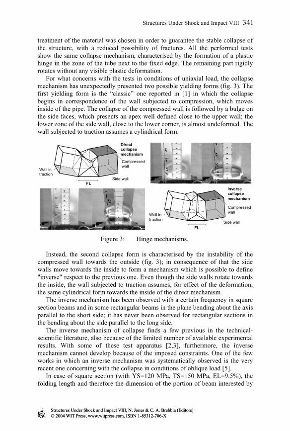
treatment of the material was chosen in order to guarantee the stable collapse of the structure, with a reduced possibility of fractures. All the performed tests show the same collapse mechanism, characterised by the formation of a plastic hinge in the zone of the tube next to the fixed edge. The remaining part rigidly rotates without any visible plastic deformation. For what concerns with the tests in conditions of uniaxial load, the collapse mechanism has unexpectedly presented two possible yielding forms (fig. 3). The first yielding form is the “classic” one reported in [1] in which the collapse begins in correspondence of the wall subjected to compression, which moves inside of the pipe. The collapse of the compressed wall is followed by a bulge on the side faces, which presents an apex well defined close to the upper wall; the lower zone of the side wall, close to the lower corner, is almost undeformed. The wall subjected to traction assumes a cylindrical form.
Parete compressa
Parete laterale
Parete in trazione
Lf
Cinematismo flessionale inverso
Parete compressa
Parete laterale
Parete in trazione
Lf
Cinematismo flessionale diretto
Direct collapse mechanism
Inverse collapse mechanism
FL
FL Side wall
Side wall
Compressed wall
Compressed wall
Wall in traction
Wall in traction
Figure 3: Hinge mechanisms. Instead, the second collapse form is characterised by the instability of the compressed wall towards the outside (fig. 3); in consequence of that the side walls move towards the inside to form a mechanism which is possible to define "inverse" respect to the previous one. Even though the side walls rotate towards the inside, the wall subjected to traction assumes, for effect of the deformation, the same cylindrical form towards the inside of the direct mechanism. The inverse mechanism has been observed with a certain frequency in square section beams and in some rectangular beams in the plane bending about the axis parallel to the short side; it has never been observed for rectangular sections in the bending about the side parallel to the long side. The inverse mechanism of collapse finds a few previous in the technical-scientific literature, also because of the limited number of available experimental results. With some of these test apparatus [2,3], furthermore, the inverse mechanism cannot develop because of the imposed constraints. One of the few works in which an inverse mechanism was systematically observed is the very recent one concerning with the collapse in conditions of oblique load [5]. In case of square section (with YS=120 MPa, TS=150 MPa, EL=9.5%), the folding length and therefore the dimension of the portion of beam interested by
Structures Under Shock and Impact VIII, N. Jones & C. A. Brebbia (Editors)© 2004 WIT Press, www.witpress.com, ISBN 1-85312-706-XStructures Under Shock and Impact VIII, N. Jones & C. A. Brebbia (Editors)© 2004 WIT Press, www.witpress.com, ISBN 1-85312-706-X
Structures Under Shock and Impact VIII 341

the plastic hinge is about the 30% lower than the one described by Kecman [1] and used in his collapse model. The folding length increases with different heat treatment (with YS=80 MPa, TS=135 MPa, EL=11%); also the distance of the plastic hinge from the constraint increases in this case. The tendency to an increase of the folding length with the annealing temperature is confirmed also by the rectangular section beams with thickness 2 mm, even if in this case the change is less clear; the folding length is still next to the dimension of the smaller side. For the section 60x40 with thickness 1.1 mm no change in the folding length was observed: for such geometry the wall instability is however presumably of elastic type.
Figure 4: Mechanisms of collapse with the changing of the angle of rotation of the bending plane.
For what concerns with the collapse in biaxial loading conditions, the collapse mechanism is, as predictable, asymmetrical. In case of square section beams (fig. 4) the collapse mechanism modifies constantly passing from the uniaxial collapse (γ=0°) to the angle γ=45°. Unlike the numerical models of [6,7], the loading condition γ=45° also produces a asymmetrical mechanism, even though the mechanism of collapse keeps a certain regularity respect to the B.P. The biaxial loading seems to emphasise the tendency to “inverse” collapse forms: as shown in figure 5, the more compressed wall (parallel to w) tends to buckle towards the outside one, unlike the numerical models of [6,7] for which the wall instability is always internal. For what concerns with the rectangular section beams, it is interesting to notice that, for loading angle lower than, approximately, the angle for which the bending plane passes through the corners of the section, the collapse mechanism is very similar to the one obtained for the numerical models [6,7]. The collapse mechanism gradually becomes asymmetrical and the wall parallel to the long side buckles inward. Instead, for higher biaxiality angle, the collapse mechanism is different from what expected
Structures Under Shock and Impact VIII, N. Jones & C. A. Brebbia (Editors)© 2004 WIT Press, www.witpress.com, ISBN 1-85312-706-XStructures Under Shock and Impact VIII, N. Jones & C. A. Brebbia (Editors)© 2004 WIT Press, www.witpress.com, ISBN 1-85312-706-X
342 Structures Under Shock and Impact VIII

on the basis of the numerical models: irregular collapse forms or inverse collapse mechanisms were observed. An important aspect of the collapse in conditions of biaxial load is represented by the possibility of fractures of the wall in correspondence of the corner subjected to the maximum tensile stress (fig. 5).
// A.N. P.F.
w
s
θ
Innesco della frattura
// N.A. B.P.
Fracture beginning
Figure 5: Zone of fracture beginning. If the material is sufficiently ductile the wall reaches a high elongation before fracturing; instead, in brittle material conditions, the wall fractures without evident necking. In the first case the fracture happens for the greater biaxiality angles and for high angles of rotation of the plastic hinge (>20°); in the second case the fracture appears also for low biaxiality values and rotation angles of the hinge of the order of magnitude of 10°-15°.
5 Experimental results
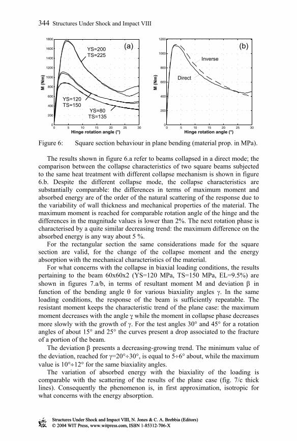
The data acquired during the experimental tests were analysed, in order to obtain the characteristics of collapse of the various test sections. For what concerns with the collapse in uniaxial loading conditions, the collapse characteristics were evaluated in terms of resistant moment and absorbed energy in function of the angle of rotation of the undeformed portion of the beam. The collapse curves for the square section beam are shown in figure 6 for three different conditions of the material and direct mechanism of collapse. The moment-angle curves present the classical trend with a first elastic phase followed by collapse condition; this condition is preceded by an elastic-plastic deformation phase and, therefore, the collapse of the section takes place for plastic buckling of the walls. Once the maximum value of the resistant moment is reached, the structures collapse and the moment assumes the typical decreasing trend until the locking condition of the mechanism is reached with consequent new increase of the moment. The value of the locking angle essentially depends on the dimension of the collapse mechanism; it is a consequence of the contact between the compressed walls of the two undeformed portions of the beam adjacent to the plastic hinge. Smaller locking angle (fig. 6) are index of smaller folding length (FL) of a mechanism respect to another. Because of the decrease of the mechanical characteristics due to the heat treatment, the maximum resistant moment (moment of collapse) and the absorbed energy (area under the moment-angle curve) decrease.
Structures Under Shock and Impact VIII, N. Jones & C. A. Brebbia (Editors)© 2004 WIT Press, www.witpress.com, ISBN 1-85312-706-XStructures Under Shock and Impact VIII, N. Jones & C. A. Brebbia (Editors)© 2004 WIT Press, www.witpress.com, ISBN 1-85312-706-X
Structures Under Shock and Impact VIII 343
0 5 10 15 20 25 300
200
400
600
800
1000
1200
1400
1600
1800
Angolo di rotazione della cerniera (°)
M (N
m)
Tric= 310°C
Tric
= 280°C
NT
0 5 10 15 20 25 300
200
400
600
800
1000
1200
Angolo di rotazione della cerniera (°)
M (N
m)
Inverso
Diretto
Hinge rotation angle (°) Hinge rotation angle (°)
Inverse
Direct
YS=200 TS=225
YS=80 TS=135
YS=120 TS=150
(a) (b)
Figure 6: Square section behaviour in plane bending (material prop. in MPa). The results shown in figure 6.a refer to beams collapsed in a direct mode; the comparison between the collapse characteristics of two square beams subjected to the same heat treatment with different collapse mechanism is shown in figure 6.b. Despite the different collapse mode, the collapse characteristics are substantially comparable: the differences in terms of maximum moment and absorbed energy are of the order of the natural scattering of the response due to the variability of wall thickness and mechanical properties of the material. The maximum moment is reached for comparable rotation angle of the hinge and the differences in the magnitude values is lower than 2%. The next rotation phase is characterised by a quite similar decreasing trend: the maximum difference on the absorbed energy is any way about 5 %. For the rectangular section the same considerations made for the square section are valid, for the change of the collapse moment and the energy absorption with the mechanical characteristics of the material. For what concerns with the collapse in biaxial loading conditions, the results pertaining to the beam 60x60x2 (YS=120 MPa, TS=150 MPa, EL=9.5%) are shown in figures 7.a/b, in terms of resultant moment M and deviation β in function of the bending angle θ for various biaxiality angles γ. In the same loading conditions, the response of the beam is sufficiently repeatable. The resistant moment keeps the characteristic trend of the plane case: the maximum moment decreases with the angle γ while the moment in collapse phase decreases more slowly with the growth of γ. For the test angles 30° and 45° for a rotation angles of about 15° and 25° the curves present a drop associated to the fracture of a portion of the beam. The deviation β presents a decreasing-growing trend. The minimum value of the deviation, reached for γ=20°÷30°, is equal to 5÷6° about, while the maximum value is 10°÷12° for the same biaxiality angles. The variation of absorbed energy with the biaxiality of the loading is comparable with the scattering of the results of the plane case (fig. 7/c thick lines). Consequently the phenomenon is, in first approximation, isotropic for what concerns with the energy absorption.
Structures Under Shock and Impact VIII, N. Jones & C. A. Brebbia (Editors)© 2004 WIT Press, www.witpress.com, ISBN 1-85312-706-XStructures Under Shock and Impact VIII, N. Jones & C. A. Brebbia (Editors)© 2004 WIT Press, www.witpress.com, ISBN 1-85312-706-X
344 Structures Under Shock and Impact VIII

It is possible to obtain the trends of the components of the bending moments about the principal axis of inertia of the section, in a way analogous to [6,7]. Once the components Mw and Ms are known, it is immediate to obtain the representation of the tests in the collapse plane (fig. 7.d). The collapse locus drawn on the basis of the experimental test results is very similar to the numerical simulations one [6,7]: the level curves (θ=cost) evolve, in collapse phase, from the limit imposed by the collapse locus (well approximated by the analytical relation presented in [6,7]) more squared shapes due to the growth of the resistant moments with the biaxiality. However there is a zone of the collapse plane (schematically highlighted by the grey line in figure 7.d) where a beam wall fractures with consequent drop of resistant capacity.
0 0.2 0.4 0.6 0.8 10
0.1
0.2
0.3
0.4
0.5
0.6
0.7
0.8
0.9
1
Mw/Mw0
Ms/
Ms0
θ=7.5°
θ=12.5°
θ=17.5° θ=22.5° θ=27.5°
(5.36)
γ=45°
γ=30°
γ=20°
γ=10°
γ=0°
X X
X
0 5 10 15 20 25 30 350
200
400
600
800
1000
1200
Angolo di rotazione della cerniera (°)
M (N
m)
0 5 10 15 20 25 30 350
200
400
600
800
1000
1200
Angolo di rotazione della cerniera (°)
M (N
m)
γ
γ
X X
X X
Hinge rotation angle (°) 0 5 10 15 20 25 30 35
-10
-5
0
5
10
15
20
Angolo di rotazione della cerniera (°)
Dev
iazi
one
della
sol
leci
tazi
one
(°)
X X
X X
γ=20°
γ=10°
γ=30°
γ=0°
γ=45°
Hinge rotation angle (°)
Dev
iatio
n - β
(°)
Analytical expression of collapse locus
0 5 10 15 20 25 30 350
50
100
150
200
250
300
350
400
450
Angolo di rotazione della cerniera (°)
Ener
gia
Ass
orbi
ta (J
)
Hinge rotation angle (°)
Abs
orbe
d en
ergy
(J)
(a) (b)
(c) (d)
Figure 7: Square section behaviour in biaxial bending.
The rectangular sections show a similar behaviour with a first phase in which the resistant moment (starting from the collapse moment) raises with the value of the loading angle γ, while in a second phase for angle of rotation θ>5° the intermediate loading angle γ (major biaxiality) presents the higher moment values. Two distinct phases, marked by different trends, are visible in the
Structures Under Shock and Impact VIII, N. Jones & C. A. Brebbia (Editors)© 2004 WIT Press, www.witpress.com, ISBN 1-85312-706-XStructures Under Shock and Impact VIII, N. Jones & C. A. Brebbia (Editors)© 2004 WIT Press, www.witpress.com, ISBN 1-85312-706-X
Structures Under Shock and Impact VIII 345

evolution of the deviation angle β: a first phase in which the deviation depends on the plasticization of the section [7], a second one in which it depends on the distribution of the stiffness in the mechanism of collapse. The level curves (θ=cost) evolve, in collapse phase, from the limit imposed by the collapse locus to more rectangular shapes due to the growth of the resistant moments with the biaxiality. On the collapse plane are well visible two trends: the transition from one to the other happens for loading angle γ next to the angle of passage of the BP through the section corners (as γ=45° for the square sections section).
6 Conclusions
An equipment for the execution of biaxial bending tests with imposed bending plane was designed and built and a wide number of bending tests on thin walled extruded beams (aluminium alloy) with square and rectangular section were performed. The collapse locus was experimentally obtained and the structural behaviour subsequent this condition was extensively studied. The campaign of experimental tests has substantially proved the guidelines emerged from the numerical/analytical analysis of previous works. However, in biaxial loading conditions, it was highlighted the possibility of fractures of the walls also for limited angle of hinge rotation. The probability to have a fracture of the wall depends on the material state, on the degree of load biaxiality, on the section geometry (a/b ratio) and on the wall thickness. Furthermore, the possibility of an inverse collapse mechanism was observed: any way, this collapse mechanism substantially presents a structural response quite similar to the "classical" mechanism for what concerns both with the uniaxial and the biaxial loading conditions.
References
[1] D. Kecman, Bending collapse of rectangular section tubes in relation to the bus roll-over problems, Ph.D. thesis, Cranfield Inst. of Technology, 1979.
[2] S. J. Cimpoeru, N. W. Murray “The large deflection pure bending properties of a square thin-walled tube”. In Int. J. of Mech. Sci. 35, pp.247-256, 1993.
[3] M. Avalle, G. Belingardi, R. Montanini “Strain field in the plastic hinge during bending collapse of thin-walled tubes by strain-gauge measurements”, in Proc. ICEM 11, Oxford (UK), (1998).
[4] Brown J. C., G. H. Tidbury, “An investigation of the collapse of thin-walled rectangular beams in biaxial bending”, Int. J. Mech. Sci., pp. 733-746, 1983.
[5] Reyes A., Langseth M., Hopperstad O.S., “Crash behavior of obliquely loaded aluminium extrusion”, SUSI VII, vol.11, (2002).
[6] L. Peroni, G. Belingardi, “Studio del collasso flessionale di profilati in parete sottile sottoposti a flessione deviata”. Proc. of the XXX Convegno Nazionale AIAS, September, 2001, Alghero.
[7] L. Peroni, Plastic collapse of thin walled structures: models and experimental investigations, Ph.D. thesis, Politecnico di Torino, 2003.
Structures Under Shock and Impact VIII, N. Jones & C. A. Brebbia (Editors)© 2004 WIT Press, www.witpress.com, ISBN 1-85312-706-XStructures Under Shock and Impact VIII, N. Jones & C. A. Brebbia (Editors)© 2004 WIT Press, www.witpress.com, ISBN 1-85312-706-X
346 Structures Under Shock and Impact VIII