experimental investigation of supercavitating flows byoung-kwon ahn*, tae-kwon lee, hyoung-tae kim...
TRANSCRIPT

Experimental Investigation of Supercavitating Flows
Byoung-Kwon Ahn*, Tae-Kwon Lee, Hyoung-Tae Kim and Chang-Sup Lee
Dept. of Naval Architecture and Ocean EngineeringCollege of Engineering, Chungnam National Univ.

Background
2
Experimental Observations
Conclusions
General Features: Numerical Results
1
3
4
CONTENTS 2

Drag in water = 103 x Drag in air Greatly increased speed by significant reduction of the drag
Conventional Torpedo: less than 55knots Super-cavitating Torpedo: more than 200knots
Super-cavitation
3BACKGROUND

Shkval II VA-111 Shkval
Shkval Early 1990s Length: 8.2m Diameter: 533mm Weight: 2700kg Warhead weight: 210kg Opt. Range: 7km Speed: 200 + knots Thrust vectoring
Super-cavitating Torpedo (Russia)
4BACKGROUND

Barracuda (Germany)• 350+α knots
SuperCav (US Navy)• under-development
5BACKGROUND
Super-cavitating Torpedo (Germany & USA)

Key technologies of Super-Cavitating Torpedo (ONR)
6BACKGROUND

x
y
UC
U
UBy0()
Developed Numerical Method:• Ideal (Incompressible, Inviscid) flow + Irrotational flow• Dipole and Source distributions on the body and cavity surfaces
loglog
2 2B C C
x
S S S
r qU x ds rds
n
7NUMERICAL ANALYSIS

8NUMERICAL ANALYSIS
• Quiescence condition at infinity:
• Flow tangency condition on the body surface:
• Kinematic condition on the cavity surface:
• Dynamic condition on the cavity surface:
• Cavity closure condition:
• Linear termination model
U
/ 0 on Bn S
( , ) / 0 on c CDf x y Dt S
vp p
. . .( ) 0cC T Et x
Primary Boundary Conditions;
Governing Equation2 0

Typical results (2D):• Pressure and velocity distributions• Cavity length and volume according to the Cav. No.
x/c0 0.5 1 1.5 2 2.5 3
-Cp
,V
t
-1.5
-1
-0.5
0
0.5
1
1.5
PressureVelocity
Cavity length = 2.0ybase/c = 0.13
Wedge Angle(deg) = 15Cavitation Number = 0.27
212
vp p
U
9NUMERICAL ANALYSIS

10NUMERICAL ANALYSIS
Predicted super-cavity length and shape

11NUMERICAL ANALYSIS
Comparison with analytic solutions (by J. N. Newman)
Cavitation No. ( / 4 y 0)
Cavit
yL
en
gth
(no
nd
imen
sio
n)
0 0.5 1 1.5 2 2.5 30
1
2
3
4
5
6
7
8
9
10
Analytic SolutionPresent
Cavitation No. ( / 4 y 0)
Dra
gC
oe
ffic
ien
t(
Cd
/2(y
0)2
)
0.5 1 1.5 2 2.5 33
4
5
6
7
8
9
10
Analytic SolutionPresent

Wedge angle = 45 deg
x/c0 1 2 3 4 5 6 7 8 9 10 11 12 13
y/c
-3
-2
-1
0
1
2
3
4
5
Cavity length, on x-axis = 9.0Cavity length, girthwise = 9.39
Wedge Angle(deg) = 45ybase/Chord = 0.41
Cavitation Number = 0.35
x/c0 1 2 3 4 5 6 7 8 9 10 11 12 13
y/c
-3
-2
-1
0
1
2
3
4
5
Cavity length, on x-axis = 9.0Cavity length, girthwise = 11.4
Wedge Angle(deg) = 90ybase/Chord = 1.0
Cavitation Number = 0.72
Wedge angle = 90 deg
12NUMERICAL ANALYSIS
Super-cavity of the blunt body

13NUMERICAL ANALYSIS
Predicted cavity length and drag forces
Cavitation No. ()
Cav
ity
Len
gth
/Cav
itat
orW
idth
0 0.2 0.4 0.6 0.8 1 1.2 1.4 1.60
5
10
15
20
25
30
35
40
10 o
30 o
60 o
90 o
Cavitation No. ()
Dra
gC
oeff
icie
nt
0 0.1 0.2 0.3 0.4 0.5 0.6 0.7 0.8 0.9 10
0.5
1
1.5
10 o
30 o
60 o
90 o

14NUMERICAL ANALYSIS
Three dimensional analysis

15NUMERICAL ANALYSIS
Cavity length and maximum diameter
Cavitation number
Ca
vity
ma
xim
um
dia
me
ter
/C
avi
tato
rd
iam
ete
r
0 0.05 0.1 0.15 0.2 0.25 0.30
1
2
3
4
5
6
Cone(90°)
Disk
Cavitation number
Ca
vity
len
gth
/Ca
vita
tor
dia
me
ter
0 0.05 0.1 0.15 0.2 0.25 0.30
10
20
30
40
50
60
70
80
Cone(90°)
Disk
Self et. al (Cone)
Self et. al (Disk)
Self et. al (Cone)
Self et. al (Disk)

16NUMERICAL ANALYSIS
Drag coefficients (Disk)
Cavitation number
Dra
gco
eff
icie
nts
0 0.2 0.4 0.6 0.8 1 1.2 1.40
0.2
0.4
0.6
0.8
1
1.2
1.4
1.6
1.8
2
Panel methodFisherArmstrong and DunhamPlesset and ShafferLinear
Circular Disk

17NUMERICAL ANALYSIS
Disk type cavitator w/ dummy body
σ CD LS LS/DC DS/DC
0.34 0.82 12,000 60.0 5.6knots
De
pth
(m)
Dra
g(k
N)
100 150 200 250 300-20
-10
0
10
20
30
40
50
60
0
50
100
150
200
250
300
350
400
Depth(m)Drag(kN)
DC(mm) DB(mm) LB(mm)
200 533 8,000

Speed(knots)
De
pth
(m)
100 150 200 250 300
0
10
20
30
40
50
60
70
80
Lcav/Dh = 30Lcav/Dh = 40Lcav/Dh = 50Lcav/Dh = 60
Drag(kN)
De
pth
(m)
0 50 100 150 200 250 300
0
10
20
30
40
50
60
70
80
Lcav/Dh = 30Lcav/Dh = 40Lcav/Dh = 50Lcav/Dh = 60
18NUMERICAL ANALYSIS
Predicted drag forces and required speed in practical conditions

19
CNU Cavitation Tunnel
EXPERIMENTAL OBSERVATIONS

2D Cavitator Analysis & Exp. observation: (V=8.10~10.32m/s)
20EXPERIMENTAL OBSERVATIONS

21EXPERIMENTAL OBSERVATIONS
V=9.4m/s, σ=1.11 V=9.8m/s, σ=1.13
V=9.4m/s, σ=1.16 V=9.8m/s, σ=1.17
V=9.4m/s, σ=1.16 V=9.8m/s, σ=1.17
30˚
45˚
Flat plate
w/o body w/ body
2D Cavitators

Hi-speed Camera
22EXPERIMENTAL OBSERVATIONS
Max Frame Rate 250,000 fps
Max Resolution 1,024 x 1,024
Max at Max Res. 3,000 fps
Max. Rec. Time at 1,000 fps (highest res.)
12.3 sec

23EXPERIMENTAL OBSERVATIONS
Hi-speed Camera (5,000 fps)Video Camera (30 fps)σ=0.83
2D Cavitators

24EXPERIMENTAL OBSERVATIONS
2D Cavitators

2D Cavitators
25EXPERIMENTAL OBSERVATIONS
σ=1.05 σ=0.70

26EXPERIMENTAL OBSERVATIONS
2D Cavitators

Value
Speed (m/s) 11
Temp (C°) 14.0
Density (kg/m3) 997.104
Vapor pressure (Pa) 1,598.14
Depressurized (bar) -0.412 ~ -0.657
σn 2.091 ~ 0.567
3D Cavitators
27EXPERIMENTAL OBSERVATIONS
30mm
30m
m
75mm 75mm
11
22
33 44

28EXPERIMENTAL OBSERVATIONS
Speed(m/s) Temp(C°) Density(kg/m3) Vapor pressure (Pa) Depressurized(bar) σn
11 14.0 997.104 1,598.14 -0.412 ~ -0.657 2.09 ~ 0.57
3D Cavitators

Disk
Disk w/ round
Cone
29EXPERIMENTAL OBSERVATIONS
1.25 0.98 0.88 0.83 0.65
Disk w/ hole
3D Cavitators
σ =
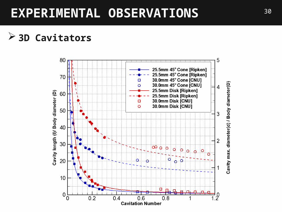
30EXPERIMENTAL OBSERVATIONS
3D Cavitators

Develop a numerical method to predict supercavity Investigate important features of supercavity: cavity length, diameter and drag forcesResults are validated by comparison with existing analytic and empirical values
Observe the early stage of the supercavity profiles generated by various 2D and 3D cavitatorsAccumulate experimental data for parametric information to design of the cavitatorAdditional experiments are on going; ventilation effects, pressure force measurements
Numerical Analysis:
31CONCLUSIONS
Experimental Observations:

Experimental Investigation of Supercavitating Flows
Byoung-Kwon Ahn*, Tae-Kwon Lee, Hyoung-Tae Kim and Chang-Sup Lee
Dept. of Naval Architecture and Ocean EngineeringCollege of Engineering, Chungnam National Univ.