experimental investigation of wedm on · pdf filenumber of non-traditional machining ... metal...
TRANSCRIPT
International Conference on Current Research in Engineering Science and Technology (ICCREST-2016)
E-ISSN :2348 - 8360 www.internationaljournalssrg.org Page 62
EXPERIMENTAL INVESTIGATION OF WEDM ON INCONEL 718 USING ZINC
COATED WIRE WITH GR AND RSM
M.VADIVEL 1 Dr. S. DHANABALAN 2, 1PG Scholar, Dept of Mechanical Engineering. 2 Professor/HOD, Dept of Mechanical Engineering,
Shivani College of Engg.&Tech , Trichy 620 009, Shivani College of Engg.&Tech, Trichy 620 009, Trichy, India Trichy, India
P.Viswabharathy3 3 Assistant Professor Dept of Mechanical Engineering
Shivani College of Engg.&Tech 620 009, Trichy, India
ABSTRACT
Wire Electrical Discharge Machining (WEDM) is a metal-working process whereby material is removed from a conductive work piece by electrical erosion. This project work focuses on finding out the optimum parameters in Wire - EDM for machining of Inconel 718. The major application of the Inconel 718 material is in the aerospace industry, both in airframes and engine components. Input process parameters that are taken into consideration are wire feed rate, Pulse on time, Pulse off time, Peak current, and Servo voltage. Output parameters are Material removal rate (MRR), Machining Time (T), Surface roughness (SR), Accuracy (Inconel718) and Wear (electrode) for surface is measured. Wire material like Zn-Coated Brass wire is used in this experiment. For design of experiment Taguchi methodology of L18 orthogonal array is used. And optimization of parameters is done with the help of Grey relational analysis (GRA) and Response surface methodology (RSM).
Key words: Inconel 718,Wire EDM, MRR, surface roughness. I.INTRODUCTION
Manufacturing industry is becoming even more conscious about time and quality with respect to the demand, efficiency, global acceptance and competence, also the need to use complicated and precise components having some special shape with high tolerances. The demand for hard, temperature resistive, tough, abrasive, wear and corrosive resistant material are growing day by day. These market trends have enforced on the use of
new and advanced technologies for higher
conversion rate of raw materials turning into finished goods; with less or possibly no time being required for tooling and other unnecessary operations.

International Conference on Current Research in Engineering Science and Technology (ICCREST-2016)
E-ISSN :2348 - 8360 www.internationaljournalssrg.org Page 63
The conventional machining processes, in spite of recent technical advancement, are inadequate to machine complex shapes in hard, high strength temperature resistant alloys and die steels. Keeping these requirements into mind, a number of Non-traditional machining (NTM)/unconventional processes have been developed. Nevertheless, such materials are difficult to be machined by traditional machining methods. Hence, nontraditional machining methods including electrochemical machining, ultrasonic machining, electrical discharging machine (EDM) etc. are applied to machine such difficult to machine materials. The unconventional methods of machining have several specific advantages over conventional methods of machining and these methods are not limited by hardness, toughness and brittleness of materials and can produce any intricate shape on any work piece material by suitable control over the various physical parameters of the processes. However unconventional methods are not substitutes for conventional machining methods, but are only complementing them. Traditional machining processes may have many difficulties in machining such materials. In machining extremely hard and brittle materials, conventional processes may not be feasible, satisfactory or economical due to the following characteristics,
i) Metal removal by chip formation is an expensive and difficult process.
ii) Chips produced during the process are an unwanted by-product.
ii) Removal of these chips and their disposal and recycling is a very cumbersome procedure, involving energy and money.
Proper holding of the work piece and to avoid its distortion are very important, due to the very large cutting forces involved. v) Due to the large cutting forces and large amount
of heat generated at the tool Desirable effects have to be removed afterwards.

International Conference on Current Research in Engineering Science and Technology (ICCREST-2016)
E-ISSN :2348 - 8360 www.internationaljournalssrg.org Page 64
vi) The tool is harder than work piece. vii) There is a direct mechanical contact between the tool and the work piece.
For developing most of these methods was the search for better ways of machining complex shapes (dies, moulds etc.) in hard, high, strength temperature resistant alloys, such as carbides, titanium alloys, hast alloy, nit alloy, wasp alloy, stainless steel and heat resisting steels etc. The use of these difficult to machine materials has led to rapid developments in the aerospace and nuclear engineering industries. Besides, machining of these materials into complex shapes is difficult, time consuming and sometimes impossible. Non-traditional manufacturing processes are classified by distinct machining mechanisms, machining system components and technological characteristics.
The new technological processes can be classified into various group according to, (a) Type of energy required to shape materials - mechanical, thermal and electro thermal or chemical and electrochemical; (b) basic mechanism involved in the process – erosion, ionic dissolution, vaporization; (c) source of energy required for material removal – hydrostatic pressure, high current density, high voltage, ionized material; (d) medium for transfer of these energies – high velocity particles, electrolyte, electron, hot gases.
The beginning of EDM came during the Second World War, when two Russian physicists B.R. and N.I. Lazarenko published their study on the Inversion of the Electric Discharge Wear Effect, which related to the application to manufacturing technology of the capacity of electrical discharges, under controlled distribution, to remove metal. EDM was being used at that time to remove broken taps and drills. The early “Tap-Busters” disintegrated taps with hand fed electrodes, burning a hole in the center of the tap or drill, leaving there mining fragments that could be picked out.
Major development of EDM was observed when computer numerical control systems were applied for the machine tool industry. Thus, the EDM process became automatic and unattended machining method. At the present time, Electrical discharge machine (EDM) is a widespread technique used in industry for high precision machining of all types of conductive materials such as: metals, metallic alloys, graphite, or even some ceramic materials, of whatever hardness.
Electrical discharge machine (EDM) technology is increasingly being used in tool, die and mould making industries, for machining of heat treated tool steels and advanced materials (super alloys, ceramics, and metal matrix composites)
requiring high precision, complex shapes and high surface finish. Traditional

International Conference on Current Research in Engineering Science and Technology (ICCREST-2016)
E-ISSN :2348 - 8360 www.internationaljournalssrg.org Page 65
machining technique is often based on the material removal using tool material harder than the work material and is unable to machine them economically. An electrical discharge machining (EDM) is based on the eroding effect of an electric spark on both the electrodes used. Electrical discharge machining (EDM) actually is a process of utilizing the removal phenomenon of electrical discharge in dielectric. Therefore, the electrode plays an important role, which affects the material removal rate and the tool wear rate .
In this process thermal energy is used to generate heat that melts and vaporizes the work piece by ionization within the dielectric medium. The electrical discharges generate impulsive pressure by dielectric explosion to remove the melted material. Thus, the amount of removed material can be effectively controlled to produce complex and precise machine components. A. Wire Electrical Discharge Machining (WEDM)
The world’s first WEDM was produced by the SWISS FIRM „AGIE‟ in 1969. The first WEDM machine worked simply without any complication and wire choices were limited to copper and brass only. Wire EDM efficiency and productivity have been improved through progress in different aspects of WEDM such as quality, accuracy, and precision.
It can machine anything that is electrically conductive regardless of the hardness, from relatively common materials such as tool steel, aluminum, copper, and graphite, to exotic space-age alloys including hastalloy, waspalloy, inconel, titanium, carbide, polycrystalline diamond compacts and conductive ceramics. The wire does not touch the work piece, so there is no physical pressure imparted on the work piece compared to grinding wheels and milling cutters. The amount of clamping pressure required to hold small, thin and fragile parts is minimal, preventing damage or distortion to the work piece.
Wire EDM also gives designers more latitude in designing dies, and management more control of manufacturing, since the machining is completed automatically. Most work pieces come off the machine as a finished part, without the need for secondary operations. It's a one-step process. B. Major Components of Wire-EDM:-
A Wire EDM system is comprised of four major components.
1) Computerized Numerical Control (CNC) Think of this as “The Brains.”
2) Power Supply Provides energy to the spark. Think of this as “The Muscle.”
3) Mechanical Section Worktable, work stand, taper unit, and wire drive mechanism..(This
is the actual machine tool.)Think of this as “The Body.”

International Conference on Current Research in Engineering Science and Technology (ICCREST-2016)
E-ISSN :2348 - 8360 www.internationaljournalssrg.org Page 66
C. Principle of Wire - EDM
The Spark Theory on a wire EDM is basically the same as that of the vertical EDM process. In wire EDM, the conductive materials are machined with a series of electrical discharges (sparks) that are produced between an accurately positioned moving wire (the electrode) and the work piece. High frequency pulses of alternating or direct current is discharged from the wire to the work piece with a very small spark gap through an insulated dielectric fluid (water).
Many sparks can be observed at one time. This is because actual discharges can occur more than one hundred thousand times per second, with discharge sparks lasting in the range of 1/1,000,000 of a second or less. The volume of metal removed during this short period of spark discharge depends on the desired cutting speed and the surface finish required. The wire electrode is usually a spool of brass, copper or brass and zinc wire from 0.001 to 0.014” thick.
Figure 1.3 Schematic Diagram of WEDM Process The heat of each electrical spark,
estimated at around 15,000° to 21,000° Fahrenheit, erodes away a tiny bit of material that is vaporized and melted from the work piece and some of the wire material is also eroded away. The water also prevents heat build-up in the work piece. Without this cooling, thermal expansion of the part would affect size and positional accuracy. Like any other machining tool, wire EDM removes material; but wire EDM removes material with electricity by means of spark erosion. Therefore, material that must be EDM must be electrically conductive.
When sufficient voltage is applied, the fluid ionizes. Then a controlled spark precisely erodes a small section of work piece, causing it to melt and vaporize. These electrical pulses are repeated thousands of time per second. The pressurized cooling fluid, the dielectric, cools the vaporized metal and forces the solidifies eroded particles from the gap.To maintain machine and part accuracy, the dielectric fluid flows through a chiller to keep the liquid at constant temperature. D. Technology of Spark Erosion:
EDM is a thermal process; material is removed by heat. Heat is introduced by the flow of
electricity between the electrode and work piece in the form of a spark. The electrode must always be
International Conference on Current Research in Engineering Science and Technology (ICCREST-2016)
E-ISSN :2348 - 8360 www.internationaljournalssrg.org Page 67
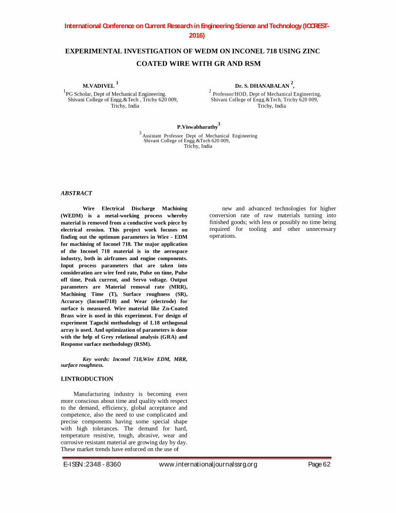
spaced away from the work piece by the distance required for sparking, known as the sparking gap ,
Figure 1.5 Sparking occurs at closest points between the Electrode and Work piece
A Figure 1.5 shows what happens with the charged electrode is first brought near the workpiece. As the potential difference increase between the surfaces, the dielectric fluid breakdown and becomes ionic (electrical conductive). The electrical field strongest at the point where the distance between the surface is minimal; thus the spark will occur at this location. At these points, sparking voltage causes the dielectric fluid to change from an insulator toa conductor and the spark occurs. The time at which the fluid changes into an electrical conductor is known as the ionization point. When the spark is turned off, the dielectric fluid deionizes and the fluid returns to being an electrical insulator. This change of the dielectric fluid from an insulator to a conductor, and then back to an insulator, happensforeach spark. Figure 1.6 shows the Next spark occurs at closest points between electrode and workpiece. Dielectric fluid used in EDM machines provides important functions in the EDM process. These are:
1. Controlling the sparking-gap spacing between the electrode and work piece;
2. Cooling the heated material to form the EDM chip; and
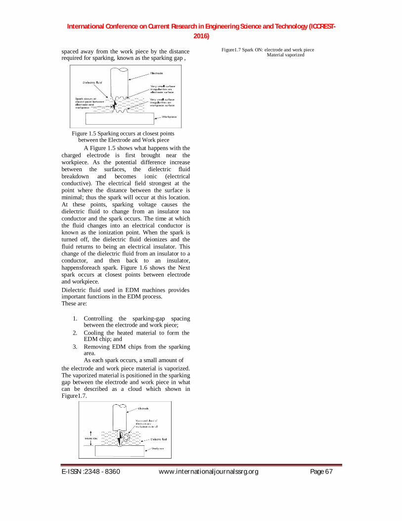
3. Removing EDM chips from the sparking area. As each spark occurs, a small amount of
the electrode and work piece material is vaporized. The vaporized material is positioned in the sparking gap between the electrode and work piece in what can be described as a cloud which shown in Figure1.7.
Figure1.7 Spark ON: electrode and work piece Material vaporized
International Conference on Current Research in Engineering Science and Technology (ICCREST-2016)
E-ISSN :2348 - 8360 www.internationaljournalssrg.org Page 68
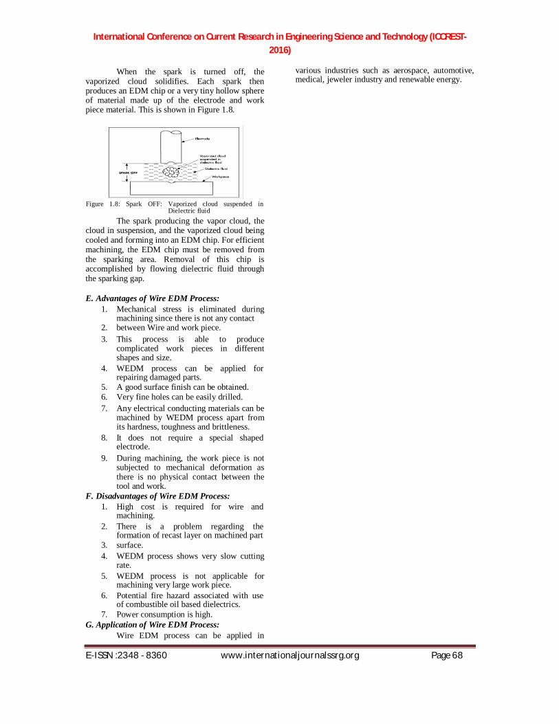
When the spark is turned off, the
vaporized cloud solidifies. Each spark then produces an EDM chip or a very tiny hollow sphere of material made up of the electrode and work piece material. This is shown in Figure 1.8. Figure 1.8: Spark OFF: Vaporized cloud suspended in
Dielectric fluid The spark producing the vapor cloud, the
cloud in suspension, and the vaporized cloud being cooled and forming into an EDM chip. For efficient machining, the EDM chip must be removed from the sparking area. Removal of this chip is accomplished by flowing dielectric fluid through the sparking gap. E. Advantages of Wire EDM Process:
1. Mechanical stress is eliminated during machining since there is not any contact
2. between Wire and work piece. 3. This process is able to produce
complicated work pieces in different shapes and size.
4. WEDM process can be applied for repairing damaged parts.
5. A good surface finish can be obtained. 6. Very fine holes can be easily drilled. 7. Any electrical conducting materials can be
machined by WEDM process apart from its hardness, toughness and brittleness.
8. It does not require a special shaped electrode.
9. During machining, the work piece is not subjected to mechanical deformation as there is no physical contact between the tool and work.
F. Disadvantages of Wire EDM Process: 1. High cost is required for wire and
machining. 2. There is a problem regarding the
formation of recast layer on machined part 3. surface. 4. WEDM process shows very slow cutting
rate. 5. WEDM process is not applicable for
machining very large work piece. 6. Potential fire hazard associated with use
of combustible oil based dielectrics. 7. Power consumption is high.
G. Application of Wire EDM Process: Wire EDM process can be applied in
various industries such as aerospace, automotive, medical, jeweler industry and renewable energy.

International Conference on Current Research in Engineering Science and Technology (ICCREST-2016)
E-ISSN :2348 - 8360 www.internationaljournalssrg.org Page 69
Also, WEDM process is one of the best choices for producing tall parts, long tubes, large heavy gears and cavities in one side of tube. H.The process is used in the following areas:
1. Aerospace, Medical, Electronics and Semiconductor applications.
2. Tool & Die making industries. 3. For cutting the hard Extrusion Dies. 4. In making Fixtures, Gauges & Cams. 5. Cutting of Gears, Punches and Dies. 6. Manufacturing hard Electrodes. In this chapter, one has discussed about the
history, principle, spark erosion process, application of WEDM process. Also, discussed about the Non-Traditional machining and specially WEDM process which all are basic about the WEDM.
II.LITERATURE REVIEW
BijayaBijetaNayak et al [1](2015)The present work proposes an experimental investigation and optimization of various process parameters during taper cutting of deep cryo-treated Inconel 718 in wire electrical discharge machining process. Taguchi’s design of experiment is used to gather information regarding the process with less number of experimental runs considering six input parameters such as part thickness, taper angle, pulse duration, discharge current, wire speed and wire tension. Since traditional Taguchi method fails to optimize multiple performance characteristics, maximum deviation theory is applied to convert multiple performance characteristics into an equivalent single performance characteristic. Due to the complexity and nonlinearity involved in this process, good functional relationship with reasonable accuracy between performance characteristics and process parameters is difficult to obtain. To address this issue, the present study proposes artificial neural network (ANN) model to determine the relationship between input parameters and performance characteristics. Finally, the process model is optimized to obtain a best parametric combination by a new meta-heuristic approach known as bat algorithm. The results of the proposed algorithm show that the proposed method is an effective tool for simultaneous optimization of performance characteristics during taper cutting in WEDM process.
RavindranadhBobbili*, etal [2] (2015)In the current investigation, a multi response optimization technique based on Taguchi method coupled with Grey relational analysis is planned for wire-EDM operations on ballistic grade aluminium alloy for armour applications. Experiments have been performed with four machining variables:
pulse-on time, pulse-off time, peak current and spark voltage. Experimentation has been planned as

International Conference on Current Research in Engineering Science and Technology (ICCREST-2016)
E-ISSN :2348 - 8360 www.internationaljournalssrg.org Page 70
per Taguchi technique. Three performance characteristics namely material removal rate (MRR), surface roughness(SR) and gap current (GC) have been chosen for this study. Results showed that pulse-on time, peak current and spark voltage were significant variables to Grey relational grade. Variation of performance measures with process variables was modeled by using response surface method. The confirmation tests have also been performed to validate the results obtained by Grey relational analysis and found that great improvement with 6% error is achieved.
RavindranadhBobbili*,et,al,[3], (2015) The current work presents a comparative study of wire electrical discharge machining (WEDM) of armour materials such as aluminum alloy 7017 and rolled homogeneous armour (RHA) steel using Buckingham pi theorem to model the input variables and thermo-physical characteristics of WEDM on material removal rate (MRR) and surface roughness (Ra) of Al 7017 and RHA steel. The parameters of the model such as pulse-on time, flushing pressure, input power, thermal diffusivity and latent heat of vaporization have been determined through design of experiment methodology. Wear rate of brass wire increases with rise in input energy in machining Al 7017. The dependence of thermo-physical properties and machining variables on mechanism of MRR and Ra has been described by performing scanning electron microscope (SEM) study. The rise in pulse-on time from 0.85ms to 1.25ms causes improvement in MRR and deterioration of surface finish. The machined surface has revealed that craters are found on the machined surface. The propensity of formation of craters increases during WEDM with a higher current and larger pulse-on time.
NeerajSharma ,et al [4] (2015), Wire electric discharge machining (WEDM) is a thermo-electric spark erosion non-traditional type manufacturing process. The applications of WEDM have been found in aerospace and die manufacturing industries, where precise dimensions were the prime objective. This process is applied in case of processing difficult to machine material. Brass wire is used as an electrode and High strength low alloy(HSLA) steel as a work-piece during experimentation. The present research deals with the effect of process parameters on the overcut while machining the HSLA steel on WEDM. The mathematical model has been developed with the help of Response Surface Methodology (RSM). Further this model is processed with help of Genetic Algorithm (GA) to find out the optimum machining parameters. The percentage error between the predicted and experimental values lies
in the range of ±10%, which indicates that the developed model can be
International Conference on Current Research in Engineering Science and Technology (ICCREST-2016)
E-ISSN :2348 - 8360 www.internationaljournalssrg.org Page 71
utilized to predict the overcut values. The experimental plan was executed according to central composite design. The optimal setting of process parameters is pulse ontime-117 ms; pulse off-time-50 ms; spark gap voltage-49 V; peak current-180 A and wire tension-6 g; for minimum overcut, whereas at the optimal setting overcut is 9.9922 mm.
P. Sivaprakasam, et al [5] (2014),Micro-machining technology is effectively used in modern manufacturing industries. This paper investigates the influence of three different input parameters such as voltage, capacitance and feed rate of micro-wire electrical discharge machining (micro-WEDM) performances of material removal rate (MRR),Kerf width (KW) and surface roughness (SR) using response surface methodology with central composite design (CCD). The experiments are carried out on titanium alloy (Tie6Ale4V). The machining characteristics are significantly influenced by the electrical and non-electrical parameters in micro-WEDM process. Analysis of variance (ANOVA) was performed to find out the significant influence of each factor. The model developed can use a genetic algorithm (GA) to determine the optimal machining conditions using multi-objective optimization technique. The optimal machining performance of material removal rate, Kerf width and surface roughness are 0.01802 mm3/min, 101.5 mm and 0.789 mm respectively, using this optimal machining conditions viz. voltage 100 V, capacitance 10 nF and feed rate15 mm/s.
III.EXPERIMENTAL SETUP A. Wire Cut Electro Discharge Machine [WEDM]
The Spark Theory on a wire EDM is basically the same as that of the vertical EDM process. In wire EDM, the conductive materials are machined with a series of electrical discharges (sparks) that are produced between an accurately positioned moving wire (the electrode) and the work piece. High frequency pulses of alternating or direct current is discharged from the wire to the work piece with a very small spark gap through an insulated dielectric fluid (water). B. Major Components of WEDM 1. Machine
For this experiments machine used is Electronica Sprint cut Wire cut EDM, Model Sodick ag600L, incorporated with Half Hard Brass wire and Zinc coated brass wire.
International Conference on Current Research in Engineering Science and Technology (ICCREST-2016)
E-ISSN :2348 - 8360 www.internationaljournalssrg.org Page 72
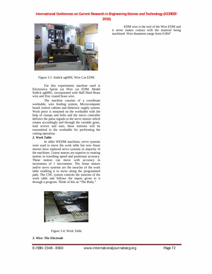
Figure 3.1: Sodick ag600L Wire Cut EDM
For this experiments machine used is Electronica Sprint cut Wire cut EDM, Model Sodick ag600L, incorporated with Half Hard Brass wire and Zinc coated brass wire.
The machine consists of a coordinate worktable, wire feeding system, Microcomputer based control cabinet and dielectric supply system. Work piece is mounted on the worktable with the help of clamps and bolts and the micro controller delivers the pulse signals to the servo motors which rotates accordingly and through the variable gears, lead screws and nuts, these motions will be transmitted to the worktable for performing the cutting operation. 2. Work Table
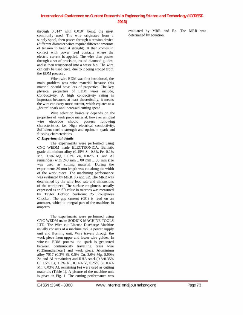
In older WEDM machines, servo systems were used to move the work table but now linear motors have replaced servo systems in majority of the machines. Linear motors are superior to rotating motors in travelling speed and positional accuracy. These motors can move with accuracy in increments of 1 micrometer. The linear motors and/or servo systems are the muscles of the work table enabling it to move along the programmed path. The CNC system controls the motions of the work table and follows the inputs given to it through a program. Think of this as “The Body.”
Figure 3.4: Work Table 3. Wire: The Electrode
EDM wire is the tool of the Wire EDM and it never makes contact with the material being machined. Wire diameters range from 0.004"
International Conference on Current Research in Engineering Science and Technology (ICCREST-2016)
E-ISSN :2348 - 8360 www.internationaljournalssrg.org Page 73
through 0.014" with 0.010" being the most commonly used. The wire originates from a supply spool, then passes through a tension device (different diameter wires require different amounts of tension to keep it straight). It then comes in contact with power feed contacts where the electric current is applied. The wire then passes through a set of precision, round diamond guides, and is then transported into a waste bin. The wire can only be used once, due to it being eroded from the EDM process .
When wire EDM was first introduced, the main problem was wire material because this material should have lots of properties. The key physical properties of EDM wires include, Conductivity, A high conductivity rating is important because, at least theoretically, it means the wire can carry more current, which equates to a „hotter‟ spark and increased cutting speed.
Wire selection basically depends on the properties of work piece material, however an ideal wire electrode should possess following characteristics, i.e. High electrical conductivity, Sufficient tensile strength and optimum spark and flushing characteristics. C. Experimental details
The experiments were performed using CNC WEDM made ELECTRONICA. Ballistic grade aluminium alloy (0.45% Si, 0.3% Fe, 0.1% Mn, 0.5% Mg, 0.02% Zn, 0.02% Ti and Al remainder) with 240 mm _ 80 mm _ 30 mm size was used as cutting material. During the experiments 80 mm length was cut along the width of the work piece. The machining performance was evaluated by MRR, IG and SR. The MRR was determined by the wire feed rate and dimensions of the workpiece. The surface roughness, usually expressed as an SR value in microns was measured by Taylor Hobson Surtronic 25 Roughness Checker. The gap current (GC) is read on an ammeter, which is integral part of the machine, in amperes.
The experiments were performed using CNC WEDM make SODICK MACHINE TOOLS LTD. The Wire cut Electric Discharge Machine usually consists of a machine tool, a power supply unit and flushing unit. Wire travels through the work piece from upper and lower wire guides. In wire-cut EDM process the spark is generated between continuously travelling brass wire (0.25mmdiameter) and work piece. Aluminium alloy 7017 (0.3% Si, 0.5% Cu, 3.0% Mg, 5.00% Zn and Al remainder) and RHA steel (0.3e0.35% C, 1.5% Cr, 1.5% Ni, 0.14% V, 0.25% Si, 0.4% Mn, 0.03% Al, remaining Fe) were used as cutting materials (Table 1). A picture of the machine unit is given in Fig. 1. The cutting performance was
evaluated by MRR and Ra. The MRR was determined by equation,
International Conference on Current Research in Engineering Science and Technology (ICCREST-2016)
E-ISSN :2348 - 8360 www.internationaljournalssrg.org Page 74
MRR (mm3/min) = cutting rate * width * depth
of work:
The surface roughness, usually expressed as a Ra value in microns was measured by Taylor Hobson Surtronic 25 Roughness Checker.
The experiments were performed on Electronica Make Elektra Sprintcut 734 wire electric discharge machine tool as shown in Fig. 3.7. The fixed process parameters are as during experimentation:
a. Workpiece: Inconel 718 b. Electrode (tool): zinc coated
Brass wire c. Conductivity: 20 mho d. Cutting voltage (V): 80 V e. Die-electric temperature: 35oC
set of precision, round diamond guides, and is then transported into a waste bin. The wire can only be used once, due to it being eroded from the EDM process. 2.Types of wires a. Copper
It was the original material first used in wire EDM. Although its conductivity rating is excellent, its low tensile strength, high melting point and low vapor pressure rating severely limited its potential b. Brass
Brass EDM wire is a combination of copper and zinc, typically alloyed in the range of 63–65% Cu and 35–37% Zn. The addition of zinc provides significantly higher tensile strength, a
f. Injection pressure set point - 7 lower melting point and higher vapor pressure kg/cm2
g. Peak voltage (VP): setting 2 h. Servo feed: 2050 units
The investigation of significant control
factors for WEDM process based on the quality of the machining are grouped in various categories. The range of all the control factors is selected for the present study based on the results obtained from preliminary experiments.
The experiments were performed on CONCORD DK7720C four axes CNC WED machine. The basic parts of the WED machine consist of a wire electrode, a work table, a servo control system, a power supply and dielectric supply system. The CONCORD DK7720C allows the operator to choose input parameters according to the material and height of the work piece. The WED machine has several special features. Unlike other WED machines, it uses the reusable wire technology. i.e., wire can’t be thrown out once used; instead it is reused adopting the re-looping wire technology. The experimental set-up for the data acquisition is illustrated in the Fig. 3.9. The WEDM process generally consists of several stages, a rough cut phase, a rough cut with finishing stage, and a finishing stage. But in this WED machine only one pass is used. D. TOOL MATERIAL: 1.Wire: The Electrode
EDM wire is the tool of the Wire EDM and it never makes contact with the material being machined. Wire diameters range from 0.004" through 0.014" with 0.010" being the most commonly used. The wire originates from a supply spool, then passes through a tension device (different diameter wires require different amounts of tension to keep it straight). It then comes in
contact with power feed contacts where the electric current is applied. The wire then passes through a

International Conference on Current Research in Engineering Science and Technology (ICCREST-2016)
E-ISSN :2348 - 8360 www.internationaljournalssrg.org Page 75
rating, which more than offsets the relative losses in conductivity. Brass quickly became the most widely used electrode material for general-purpose wire EDM. It is now commercially available in a wide range of tensile strengths and hardness. c. Coated Wires
Brass wires cannot be efficiently fabricated with any higher concentration of zinc; the logical next step was the development of coated wires, sometimes called plated or “stratified” wire. They typically have a core of brass or copper, for conductivity and tensile strength, and are electroplated with a coating of pure or diffused zinc for enhanced spark formation and flush characteristics. d. Fine Wires
Normally the wire diameters are in the range of 0.006–0.012 inches. High precision work on wire EDM machines, requiring small inside radii, and calls for wire diameters is in the range of 0.001–0.004 inches. Since brass and coated wires are not practical, due to their low load carrying capacity in these sizes, Molybdenum and tungsten wires are used. But due to limited conductivity, high melting points and low vapor pressure ratings, they are not suitable for very thick work and tend to cut slowly. These wires can be used to produce micro-parts with wire-EDM 3.Selection of electrode material Electrode materials generally used: 1) Copper 2) Brass 3) Coated wire 4) Fine wire
Wire selection basically depends on the properties of work piece material, however an ideal wire electrode should possess following characteristics, i.e. High electrical conductivity,
International Conference on Current Research in Engineering Science and Technology (ICCREST-2016)
E-ISSN :2348 - 8360 www.internationaljournalssrg.org Page 76
Sufficient tensile strength and optimum spark and flushing characteristics. For this dissertation work selected wire is Zn-Coated Brass wires.
Electrode materials to be used are as follows: Diameter of the wire materials to be used is 0.25 mm.
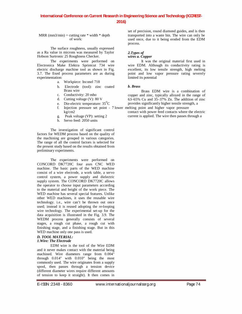
E. WORKPIECE MATERIAL: INCONEL 718 1.Chemical composition of INCONEL 718
Element Content (%)
Ni+Co 50-55
Cr 17-21
Fr Bal
Nb+Ta 4.45-5.5
Mo 2.8-3.3
Ti 0.65-1.15
Al 0.2-0.8
2. Thermal and mechanical properties of
INCONEL 718
Thermal Conductivity, 11.4
K(W/mK)
Specific Heat, C(J/kg K) 435
Density, (kg/m3) 8190
Melting temperature (K) 1609
Young’s Modulus, E (Gpa) 205
IV EXPERIMENTAL SETUP
A. WEDM Process Parameters: The process parameters that can affect the
quality of machining or cutting or drilling in Wire EDM process are shown through Ishikawa cause – effect diagram as shown in Figure 4.1. 1.The major parameters are as follows:-
1. Electrical parameters: Peak current, pulse on time, pulse off time, supply voltage and polarity.
2. Non – electrical parameters: wire speed;
work feed rate, machining time, gain and rate of flushing.
3. Electrode based parameters: Material and size of wire.
4. Dielectric system: Type, viscosity and other flow characteristics
2. Process Parameters:
There is many input parameters for Wire cut EDM are machining parameters like as pulse on time, pulse off time, flushing pressure, servo voltage, wire feed rate, wire tension and output parameters are surface roughness, kerf width and material removal rate. a. Pulse On Time (Ton):
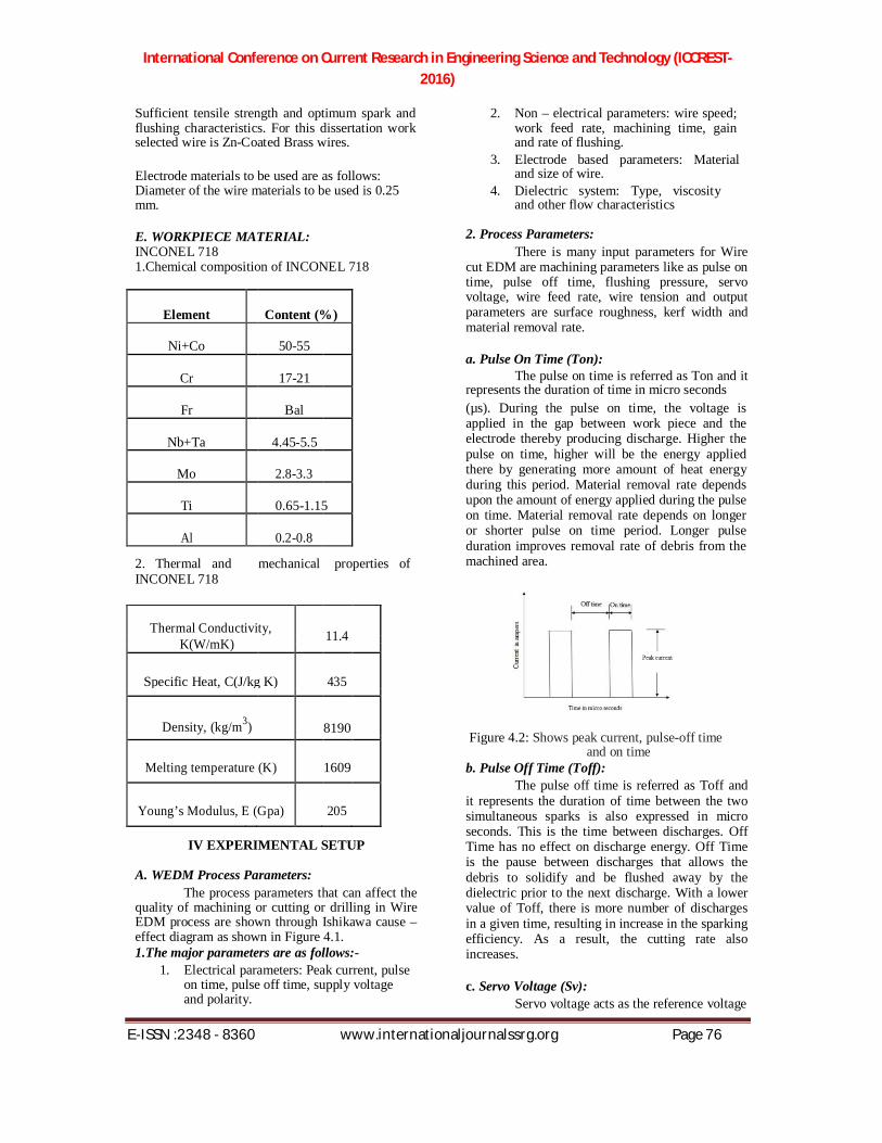
The pulse on time is referred as Ton and it represents the duration of time in micro seconds (µs). During the pulse on time, the voltage is applied in the gap between work piece and the electrode thereby producing discharge. Higher the pulse on time, higher will be the energy applied there by generating more amount of heat energy during this period. Material removal rate depends upon the amount of energy applied during the pulse on time. Material removal rate depends on longer or shorter pulse on time period. Longer pulse duration improves removal rate of debris from the machined area. Figure 4.2: Shows peak current, pulse-off time
and on time b. Pulse Off Time (Toff):
The pulse off time is referred as Toff and it represents the duration of time between the two simultaneous sparks is also expressed in micro seconds. This is the time between discharges. Off Time has no effect on discharge energy. Off Time is the pause between discharges that allows the debris to solidify and be flushed away by the dielectric prior to the next discharge. With a lower value of Toff, there is more number of discharges in a given time, resulting in increase in the sparking efficiency. As a result, the cutting rate also increases. c. Servo Voltage (Sv):
Servo voltage acts as the reference voltage

International Conference on Current Research in Engineering Science and Technology (ICCREST-2016)
E-ISSN :2348 - 8360 www.internationaljournalssrg.org Page 77
to control the wire advances and retracts. And it is also called spark gap set voltage that reference for

International Conference on Current Research in Engineering Science and Technology (ICCREST-2016)
E-ISSN :2348 - 8360 www.internationaljournalssrg.org Page 78
the actual gap between the work piece and the wire electrode used for cutting. If the mean machining voltage is higher than the set servo voltage level, the wire advances, and if it is lower, the wire retracts. When a smaller value is set, the mean gap becomes narrower, which leads to an increase in number of electric sparks, resulting in higher machining rate. d. Peak Current (Ip):
Peak current is the amount of power used in discharge machining and is measured in unit of amperage. During each pulse on-time, the current increases until it reaches a preset level, which is expressed as the peak current, is shown in Figure 3.2. In wire-EDM processes, peak current is the maximum amount of amperage is governed by the surface area of the cut. Higher amperage is used in roughing operations and in cavities or details with large surface areas. Higher currents will improve MRR, but reduce the surface roughness. e. Gap Voltage:
Gap voltage or open circuit voltage specifies the supply voltage to be placed on the gap. Greater the gap voltage, greater will be the electric discharge. If the gap voltage increases, the peak current will also increase .The open gap voltage is the voltage read across the electrode and work piece space prior to the spark. In some WEDM machines both of these factors show machining voltage. f. Dielectric flow rate:
Dielectric flow rate is the rate at which the dielectric fluid is circulated. Flushing is important for efficient machining. Flushing pressure is produced from both the top and bottom nozzles. High flow rate of dielectric is necessary for machining with higher values of pulse power and also while cutting the work piece of more thickness. Low input pressure is used for thin work piece. g. Wire Feed Rate:
Wire feed is the rate at which the wire-electrode travels along the wire guide path and is fed continuously for sparking. In WEDM, wire electrode contributes 70% of the machining cost. Therefore, it is desirable to set low wire feed rate where stable machining with no wire breakage occurs. As the wire feed rate increases, the consumption of wire as well as cost of machining will increase. Low wire speed will cause wire breakage in high cutting speed. h. Wire Tension:
Wire tension is the factor that can control
the tension of wire in WEDM. Wire tension determines how much the wire is to be stretched

International Conference on Current Research in Engineering Science and Technology (ICCREST-2016)
E-ISSN :2348 - 8360 www.internationaljournalssrg.org Page 79
between upper and lower wire guides. This is a gram-equivalent load or Newton with which the continuously fed wire is kept under tension so that it remains straight between the wire guides. If the wire tension is high enough the wire stays straight otherwise wire drags behind. Within considerable range, an increase in wire tension significantly increases the cutting speed and accuracy. The higher tension decreases the wire vibration amplitude and hence decreases the cut width so that the speed is higher for the same discharge energy. However, if the applied tension exceeds the tensile strength of the wire, it leads to wire breakage. 3. Response Variables:
Large numbers of papers have been focused on ways of yielding optimal WEDM performance. Performance measures in WEDM are MRR, SR, Kerf width, Time, Accuracy (Inconel 718), Tool wear (wire electrode). The response variables for WEDM process are discussed below. a. Material removal rate (MRR):
The material removal rate (MRR) of the work piece is the amount of the material removed per minute. In WEDM the material erodes from the work piece by a series of discrete sparks between the work and the wire electrode immersed in the liquid dielectric medium. These electrical discharges melt and vaporize minute amounts of the work material, which are then ejected and flushed away by dielectric fluid. MRR are influenced by the age and type of machine along with the properties and characteristics of the work piece being cut. b. Kerf (Width of cut):
Kerf is one of the important performance measures in WEDM. Kerf is the measure of the amount of the material that is wasted during machining.In setting the machining parameters; the main goal is the maximum MRR with the minimum Kerf width. The sparking area consists of only the front 180° of the electrode diameter as it progresses into the cut. A clearance equal to the spark length is machined on each side of the wire electrode. This side clearance is the spark overcut. The total width of the machined opening consists of the electrode diameter, plus two times the spark length. The detailed section of the Kerf is shown in Figure 4.4. c. Surface roughness (SR):
Surface roughness is one of the most important responses in WEDM machining process. SR is usually expressed in µm. Surface roughness affects several functional attributes of parts, such as
friction, wear and tear, light reflection, heat transmission, ability of distributing and holding a

International Conference on Current Research in Engineering Science and Technology (ICCREST-2016)
E-ISSN :2348 - 8360 www.internationaljournalssrg.org Page 80
lubricant, coating etc. Roughness is a measure of the texture of a surface. It is quantified by the vertical deviations of a real surface from its ideal form. If these deviations are large, the surface is rough; if small, the surface is smooth. Therefore, the desired surface finish is usually specified and appropriate processes are required to maintain the quality.
V.RESPONSE SURFACE MODELLING
Machining is the process used to convert performed shapes into desired shapes. In machining process, the drilling operations is used to make the holes on component face. The main objective of this work is to analyze and find the dependent and independent variables interactions and relationship. Decision can be made on independent variables for achieving minimum time taken to complete drilling of hole, minimum thrust force, minimum tool wear and higher surface finish. The work piece materials considered for this analysis are copper, brass, stainless steel, FRP composite and titanium alloy, tool materials are HSS and solid carbide drill bits. In this work that drilling time, thrust force, tool wear and surface roughness are considered as dependent variables and the independent variables are spindle speed and feed rate. The influences of machining parameters are dependent variables are identified with the aid of ANOVA TABLE. The dependent and independent variables interaction and their relations are formulated with the help of regression analysis. A. RESPONSE SURFACE METHODOLOGY:
Response surface methodology Montgomery (1999) refers to a collection of mathematical and statistical techniques that are useful for the modeling and analysis of problems in which a response of interest is influenced by several variables and the objective is to optimized this response. From the previous research and seeing the effect by tool geometry, the considered factors in this work were spindle speed and feed rate on machining time, tool wear, thrust force and surface finish. In order to model the interactions between these variables, the response surface methodology was assumed.
∑ ∑ ∑ ∑
When X1 and X2 represents the spindle speed and feed rate respectively, Xi
2 and XiXj, the squares and the interaction terms of these factors,
the constants b, the regression coefficient of these parameters and ɛ, the experimental error. B. ANALYSIS OF VARIANCE (ANOVA)
ANOVA is the statistical method used to calculate the size of the difference between set. The main elements of ANOVA table are source variance, sum of squares, degree of freedom, mean squares, F ratio, and the probability associated with the F ratio. The search of variance deals with the independent variables that are called factors (spindle speed and feed rate). Sum of squares (SS) SS spindle speed, SS feed rate and SS total denotes the sum of squares of spindle speed, feed rate and total variance. The degrees of freedom are equal to the number of levels for each factor -1. Mean square as a variance static, it is calculated by the sum of squares of each factor divided by corresponding degrees of freedom. F ratio is defined as the ratio between mean square values of each factor with mean square value of residual. Table 1 shows the ANOVA table for experimental data of thrust force, surface roughness as dependent variables and spindle speed and feed rate as independent variables. The design expert output as shown in the tables 1- 4 presents the analysis of variance tables for the drilling operation and also illustrates the results of ANOVA performed on machining time, thrust force, tool wear and surface roughness.
VI.RESULTS & DISCUSSION This research work has focused to find out the effect ofwire material Zn-Coated Brass wire (0.25 mm) on material removal rate (MRR), tool wear, surface roughness (SR) of Inconel 718. The input process parameters that are taken into consideration wire speed, pulse on time, pulse off time, peak current, and servo voltage.
Thus for the future work more different wire materials such as soft brass, Zn-coated copper wire, tungsten wire, molybdenum wires, molybdenum wires with graphite coating, steel wires with primary coating of copper and secondary coating of Zinc, copper wires, cryogenic treated wires can be used for analysis on different work-piece materials as Inconel, Carbides, and Mild steel, Aluminum, Sic/MMC etc. Also, effect of other process parameters such as injection pressures, wire tension, also change dielectric fluid on material removal rate, surface roughness and tool wear can be measure.
The Model F-value of 3.29 implies the model is significant. There is onlya 4.36% chance that a "Model F-Value" this large could occur due to

International Conference on Current Research in Engineering Science and Technology (ICCREST-2016)
E-ISSN :2348 - 8360 www.internationaljournalssrg.org Page 81
noise.Values of "Prob > F" less than 0.0500 indicate model terms are significant.In this case there are no significant model terms. Values

International Conference on Current Research in Engineering Science and Technology (ICCREST-2016)
E-ISSN :2348 - 8360 www.internationaljournalssrg.org Page 82
greater than 0.1000 indicate the model terms are not significant.
If there are many insignificant model terms (not counting those required to support ierarchy),model reduction may improve your model.The "Lack of Fit F-value" of 0.19 implies the Lack of Fit is not significant relative to the pureerror. There is a 95.46% chance that a "Lack of Fit F-value" this large could occur dueto noise. Non-significant lack of fit is good -- we want the model to fit.
The Std. Dev is 0.56 with a mean value of R-Squared0.6972.The R^2 and adjusted R^2 values are 8.34 & 0.4 resp. A negative "Pred R-Squared" implies that the overall mean is a better predictor of your response than the current model."Adeq Precision" measures the signal to noise ratio. A ratio greater than 4 is desirable. Your ratio of 7.758 indicates an adequate signal. This model can be used to navigate the design space. 1.Final Equation in Terms of Actual Factors: Mc time =+154.46330 * Pulse ON time=+3.61495* Pulse OFF time=+1.77655* Speed=-68.01207* Pulse ON time= -0.67790 * Pulse OFF time=- 0.29659* Pulse OFF time
2=-6.27069E-003 *
Speed2
=+7.56146
model.The "Lack of Fit F-value" of 0.19 implies the Lack of Fit is not significant relative to the pure error. There is a 95.53% chance that a "Lack of Fit F-value" this large could occur due to noise. Non-significant lack of fit is good -- we want the model tofit.
The Std. Dev.is 0.069 with mean value of 0.6532. The R^2 and adjusted R^2 values are 1.18 & 0.4641 resp.A negative "Pred R-Squared" implies that the overall mean is a better predictor of your response than the current model."Adeq Precision" measures the signal to noise ratio. A ratio greater than 4 is desirable. Your ratio of 7.564 indicates an adequate signal. This model can be used to navigate the design space.
2.Final Equation in Terms of Actual Factors:
MRR =-11.94819-0.39457 * Pulse ON time-0.25458 * Pulse OFF time +6.48248 * Speed +0.073130 * Pulse ON time * Speed+0.049017
* Pulse OFF time * Speed-0.75590 * Speed2
Fig 5.3: Effect of Speed & Pulse off time on machining time Fig 5.1: Effect of Speed & Pulse on time on machining time
Fig 5.2: Effect of Pulse off & Pulse on time on machinig Time
The Model F-value of 3.45 implies the model is
significant. There is onlya 3.61% chance that a "Model F-Value" this large could occur due to noise.Values of "Prob > F" less than 0.0500 indicate model terms are significant. In this case there are no significant model terms.Values greater than 0.1000 indicate the model terms are not significant. If there are many insignificant model
terms (not counting those required to support hierarchy), model reduction may improve your

International Conference on Current Research in Engineering Science and Technology (ICCREST-2016)
E-ISSN :2348 - 8360 www.internationaljournalssrg.org Page 83
Fig 5.4: Effect of Speed & Pulse on time on material removal rate Fig 5.5: Effect of Pulse off time & Pulse on time on material removal rate
International Conference on Current Research in Engineering Science and Technology (ICCREST-2016)
E-ISSN :2348 - 8360 www.internationaljournalssrg.org Page 84
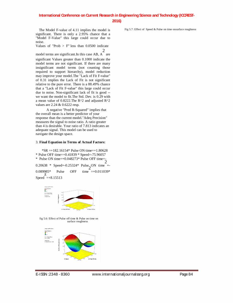
The Model F-value of 4.11 implies the model is
significant. There is only a 2.95% chance that a "Model F-Value" this large could occur due to noise. Values of "Prob > F" less than 0.0500 indicate model terms are significant.In this case AB, A
2 are
significant Values greater than 0.1000 indicate the model terms are not significant. If there are many insignificant model terms (not counting those required to support hierarchy), model reduction may improve your model.The "Lack of Fit F-value" of 0.31 implies the Lack of Fit is not significant relative to the pure error. There is a 88.49% chance that a "Lack of Fit F-value" this large could occur due to noise. Non-significant lack of fit is good -- we want the model to fit.The Std. Dev. is 0.29 with a mean value of 0.8222.The R^2 and adjusted R^2 values are 2.24 & 0.6222 resp.
A negative "Pred R-Squared" implies that the overall mean is a better predictor of your response than the current model."Adeq Precision" measures the signal to noise ratio. A ratio greater than 4 is desirable. Your ratio of 7.813 indicates an adequate signal. This model can be used to navigate the design space. 3. Final Equation in Terms of Actual Factors:
*SR =+182.16154* Pulse ON time=+1.80628 * Pulse OFF time=+0.41839 * Speed=-75.96057 * Pulse ON time=+0.048273* Pulse OFF time=- 0.20638 * Speed=-0.25324* Pulse ON time
2=-
0.089985* Pulse OFF time2
=+0.011039*
Speedz
=+8.15513
fig 5.6: Effect of Pulse off time & Pulse on time on surface roughness
Fig 5.7: Effect of Speed & Pulse on time onsurface roughness

International Conference on Current Research in Engineering Science and Technology (ICCREST-2016)
E-ISSN :2348 - 8360 www.internationaljournalssrg.org Page 85
Fig 5.8: Effect of Speed & Pulse off time on Surface Roughness
VII.CONCLUSION
The main objective of this work is to study the influence of process parameter variables effect on the machinability of the Inconel 718 material. By conducting the experiments, readings were noted for machining time, material removal rate and surface roughness. When considering the machining time, the factors pulse on time and Speed are having significant effect than the pulse off time. When considering the machining time, the factors speed and pulse on time are having significant effect than the pulse off time. When considering the machining time, the factors speed and pulse off time are having significant effect than the pulse on time. REFERENCES
[1] BijayaBijetaNayak, “Optimization of WEDM process parameters using deep cryo-treated Inconel 718 as work material” Engineering Science and Technology, an International Journal(2015)PP 1-10 .
[2] RavindranadhBobbili, “Multi response optimization of wire-EDM process parameters of ballistic grade aluminium alloy” Engineering Science and Technology, an International Journal (2015) PP 1-7.
[3] RavindranadhBobbili, “Modelling and analysis of material removal rate and surface roughness in wire - cut EDM of armour materials” Engineering Science and Technology, an International Journal (2015) PP 1-5.
[4] Neeraj Sharma, “WEDM process variables investigation for HSLA by response surface methodology and genetic algorithm” Engineering Science and Technology, an International Journal 18 (2015) PP171-177.
[5] P. Sivaprakasam, “Modeling and analysis of micro-WEDM process of titanium alloy (Tie6Ale4V) using response surface approach” Engineering Science and Technology, an International Journal 17 (2014) PP227-235.
[6] G.Ugrasen, “Process optimization and estimation of machining performances using artificial neural network in wire EDM” 3rd International Conference on Materials Processing and Characterization (ICMPC 2014).
[7] D.Sudhakara, “Application of Taguchi Method for Determining Optimum Surface Roughness in Wire Electric Discharge Machining of P/M Cold Worked Tool Steel (Vanadis-4E)” 12th Global Congress On Manufacturing And Management, Gcmm 2014.
[8] Anshuman Kumar, “Numerical Modeling of Wire Electrical Discharge Machining of Super alloy Inconel 718” 12th Global Congress On Manufacturing And Management, Gcmm 2014.
[9] Neeraj Sharma, “Modelling the WEDM Process Parameters for Cryogenic Treated D-2 Tool Steel by
integrated RSM and GA” 12th Global congress On Manufacturing And Management, Gcmm 2014.