experimental investigation on the various factors which ... · cycle. nevertheless, there ... been...
TRANSCRIPT

ISSN (e): 2250 – 3005 || Vol, 04 || Issue, 7 || July – 2014 ||
International Journal of Computational Engineering Research (IJCER)
www.ijceronline.com Open Access Journal Page 28
Experimental investigation on the various factors which
influences the fatigue-life of brass materials
1, Rajiv Ranjan,
2, Prof. Jitendra Nath Mahto,
3, Prof. Subrato kumar soren
1, M.Tech student, 2, 3, Assistant professor
Department of Mechanical Engineering BIT, Sindri, Dhanbad
I. INTRODUCTION Most of engineering failures about 90% are mainly due to fatigue in which the components are
subjected to fluctuating or cyclic loading such as suspended bridges, rails, or airplane wings. Though the
fluctuating load is normally less than the yield strength of the materials, it results in fracture behavior which is
more severe than that achieved from static loading. Fatigue failures are therefore unpredictable, and provide
high-risk situations, if the operators are not aware of material behavior when subjected to fatigue loading.
Fatigue failure is defined as the tendency of a material to fracture by means of progressive brittle cracking under
repeated alternating or cyclic stress of intensity considerably below the normal strength. Although the fracture is
of brittle type, it may take some time to propagate, depending on both intensity and frequency of the stress
cycle. Nevertheless, there is very little, if any warning below failure if the crack is not noticed. The number of cycles required to cause fatigue failure at particular endurance strength is generally quiet large, but it decreases
as the stress is increased.
A good example of fatigue failure is breaking a thin steel rod or wire with your hands after bending it
back and forth several times in the same place. Another example is an unbalanced pump impeller resulting in
vibration that can cause fatigue failure. The purpose of studying basic fatigue mechanism is to understand the
process leading to fatigue failure. Without information about these mechanisms it is difficult to design materials
with improved fatigue resistance. The fatigue resistance is measured by the number of cycles (N) a material can
resist an imposed load before it fails. Cyclic loading in general has no repeated patterns or in situations where
ABSTRACT
Brass alloy is widely used because of some attractive properties such as high electrical and
thermal conductivity. But its fatigue performance is not very well explored in literature. Thus, in the
present work, particular emphasis was given to the fatigue behavior of brass of composition 70%-
CU and 30%-ZN has been investigated with the aim of studying the factors such as annealing,
corrosion and surface roughness which influence the fatigue-life of brass materials. The endurance
limit of the specimens have been determined by testing under different loads on the fatigue testing
machine and the life cycles of each specimens has been taken after failure of the specimen. Endurance limit is defined as the alternating stress that causes failures after some specified number
of cycles. This study or investigation with the aim of studying the factors such as corrosion,
annealing and surface roughness which influence the fatigue-life of brass materials has been
investigated. Annealing was done by heating the specimens at temperature of 480 0C for 1 hours and
then allowing the specimens to cool in the control atmosphere for 3 days. Fatigue test for annealed
specimens was done and change in the fatigue endurance investigated. The specimens of groove 1
mm was prepared and the endurance limit of the specimens have been determined by testing under
different loads on the fatigue testing machine and the life cycles of each specimens has been taken
after fracture occurs on the specimen. Corrosion attack was obtained by immersion of specimens in
an salt water for 14 days in order to investigate the effect of corrosion on the fatigue-life of the
material. The corrosion agent was a solution of NaCl with a PH close to 6.5-6.8 and solution concentration of 38%.Fatigue test at a revolution of 2800 R.P.M at room temperature and without
environment humidity control was carried out on the pre-corroded and non-corroded specimens in
order to investigate the corrosion effect on the fatigue endurance Finally, conclusion is listed
concerning change in fatigue-life behavior due to annealing, groove and corrosion attacks of
surface of the brass materials.

Experimental investigation on the various factors which influences the fatigue-life of brass materials
www.ijceronline.com Open Access Journal Page 29
overloading occurs as seen in figure 1(a). However, in order to investigate the fatigue behavior according to
engineering purposes, a simple relation between stress and number of cycles to failure (time) can be expressed
in a sinusoidal curve. Fatigue behavior of materials can thus be practically described according to the parameters
given as follows;
• Maximum stress (σmax)
• Minimum stress (σmin)
• Stress range (∆σ= σmax - σmin)
• Mean stress = (σmax + σmin)/2
• Stress amplitude = (σmax - σmin)/2
• Stress ratio = (σmin / σmax)
1.1 PROBLEM STATEMENT
It has been estimated that at least 75% o all machine and structural failures have been caused by some
form of fatigue (Richard G. Budynas, 1998). Fatigue failures occur most often in moving machinery parts,
example shafts, axles, connecting rods, valves and spring. However, the wings and fuselage of an airplane or the
hull of a submarine are also susceptible to fatigue failures because in service they are subjected to variations of
stress. As it is not always possible to predict where and when fatigue failure will occur in service and because it
is essential to avoid premature fractures in articles such as aircraft components, it is common to do full-scale
testing on aircraft wings, fuselage, engine pods and others. This involve supporting the particular aircraft section
or submarine hull or car chassis in jigs and applying cyclically varying stresses using hydraulic cylinders with
specially controlled valves. According to the problems stated above, there are two main problems related to this
research which are:
1. When component breakdown down time is inevitable.
2. Unable to predict the time for preventive maintenance.
1.2 OBJECTIVE OF RESEARCH
The objective of this research is to investigate on the various factors which influence the fatigue life of
a Brass material.
II. LITERATURE REVIEW Hani Aziz Ameen et. Al.
[1] studied the effect of short and long cracks for brass alloys specimens exposed to
bending cyclic load was investigated, this test applied on a group of standard specimens until its fracture, data
taken could be drawn as a curve between stress and number of cycles (S-N) curves which gives the fatigue limit.
Results obtained theoretically and experimentally, that were concluded decreasing in the applied load cause
increasing the age and applying high loads in the beginning and at the end given almost smaller number
specimen age and the quick growth of short cracks followed by quick growth of long cracks, that the values
taken from the theoretical equations were always greater than experimental number of cycles of failure.
G. Li et. Al.[2] This paper reviews expressions to quantify fatigue lifetime for four copper alloys, Cu-Ag-P, Cu-
Cr-Zr, Cu-Ni-Be and Cu-Al2O3. These property models were needed to simulate the mechanical behavior of
structures with copper components that were subjected to high heat flux and fatigue loading conditions, such as
molds for the continuous casting of steel and wall in a fusion reactor
W. Knapp[3]
analyzed the results of a study of the effects of grain size and environment on the fatigue life of OFHC copper specimens.
Tests conducted in alternating torsion on specimens of two different grain size groups showed that an
increase in specimen grain size results in a decrease in fatigue life at both high and low strain amplitudes.
Similar tests under low and high humidity showed that humidity has a negligible effect on fatigue life for either
high or low strain amplitude and for large or small grain size. The effects of elevated temperatures were found
to be more complex.
Ahmad Fitri Bin Zainal Abidin[4] Investigated about the endurance limit of aluminum, brass and mild steel
that had been done at the surface of the specimens on different surface roughness. The endurance limit of the
specimens have been determined by testing under different loads on the fatigue testing machine and the life
cycles of each specimens has been taken after crack occur on the specimen. The different surface roughness will give different life cycles. Then, comparison of the result needs to be done to get the best materials on different
surface roughness to create a good choosing of materials in industry.

Experimental investigation on the various factors which influences the fatigue-life of brass materials
www.ijceronline.com Open Access Journal Page 30
III. EXPERIMENTATION TEST EQUIMENT, SPECIMEN PREPARATION, AND TEST
PROCEDURE 3.1 Test Equipment
3.1.1 Fatigue Machine :-The rotating bar fatigue testing machine is shown in the figure1.Two separate test bars
can be clamped at same time , one at each end of revolving shaft , one end of the test bar is fixed in clamping
sleeve , the other being loaded through a bearing with dead weight.
The number of revolutions are read off from the revolution counter, actuated by the shaft, when rupture occurs
in one of the bars, the bearing and weight fall down , where as the clutch disengage the corresponding revolution
counter when the other test bar breaks , it’s revolution will be disengaged and at the same time current supply is
cut-off thus causing the machine to stop .
Figure 3.1.1:- Fatigue testing machine
Figure 3.1.2:- Fatigue specimen.
3.2. Materials and equipment
3.2.1 Fatigue specimens
3.2.2 Micrometer or vernier caliper
3.2.3 Permanent pen
3.2.4 Fatigue testing machine
3.3 Specimen Preparation
3.3.1 Material
The material selected for these experiments was Brass .The specifications of this Brass are Copper: - 70
percent.
Zinc: - 30 percent.
This Brass was purchased in the form of rod of diameter 19mm and length of 190mm.
Alloy Modulus of Elasticity, E
(GPa)
Onset of 1st yield σcritical
(MPa)
Yield stress, σ0.2(MPa)
Cu-70%,Zn-30% 110 47 96.3
Brass has higher malleability than Bronze or Zinc. The relatively low melting point of 900ᴼC to 940ᴼC
,depending on composition and its flow characteristic make it a relatively easy to cast. The density of Brass is
approximately 8.4 to 8.73g/cmᶟ.
3.3.3 THE HARDNESS TEST Hardness may be defined as resistant of metal to plastic deformation (usually) by indentation. Hardness
is one of the most basic mechanical properties of engineering materials. Hardness test is practical and provide a
quick assessment and the result can be used as a good indicator for material selections. The main source of error
with indentation tests is the strain hardening effect of the process.
However, it has been experimentally determined through "strain less hardness tests" that the effect is
minimal with smaller indentations. Surface finish of the part and the indenter do not have an effect on the
hardness measurement, as long as the indentation is large compared to the surface roughness. This proves to be

Experimental investigation on the various factors which influences the fatigue-life of brass materials
www.ijceronline.com Open Access Journal Page 31
useful when measuring the hardness of practical surfaces. The indentation techniques used in experiment
involve Brinell hardness test.
The Brinell hardness number (BHN) is expressed as the load P divided by the surface area of the
indentation. This is expressed by the formula,
Where, P = is the applied load (kg). D =is the diameter of the steel ball (mm).
d =is the diameter of the indentation (mm).
Generally, the metal surface should be flat without oxide scales or debris because these will Significantly affect
the hardness values obtained. A good sampling size due to large steel ball diameter is advantageous for
materials with highly different microstructures or micro structural heterogeneity. Scratches or surface roughness
have very small effects on the hardness values measured
f
Fig: 3.3.3.1- A Brinell hardness testing machine.
Figure 3.3.3.2 –Brass specimen indentation after Brinel hardness test.
3.3.4 Annealing
The machined and polished specimens were then annealed in groups of 5 in a furnace at temperature of 490*c
and constant temperature is maintained for 1 hour. And then cooling was in control atmosphere of furnace for
the three days
Figure 3.3.4.1-Muffle furnace
Experimental investigation on the various factors which influences the fatigue-life of brass materials
www.ijceronline.com Open Access Journal Page 32
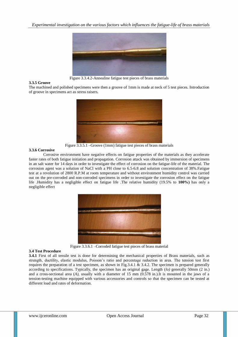
Figure 3.3.4.2-Annealine fatigue test pieces of brass materials
3.3.5 Groove The machined and polished specimens were then a groove of 1mm is made at neck of 5 test pieces. Introduction
of groove in specimens act as stress raisers.
Figure 3.3.5.1 –Groove (1mm) fatigue test pieces of brass materials
3.3.6 Corrosive Corrosive environment have negative effects on fatigue properties of the materials as they accelerate
faster rates of both fatigue initiation and propagation. Corrosion attack was obtained by immersion of specimens
in an salt water for 14 days in order to investigate the effect of corrosion on the fatigue-life of the material. The
corrosion agent was a solution of NaCl with a PH close to 6.5-6.8 and solution concentration of 38%.Fatigue
test at a revolution of 2800 R.P.M at room temperature and without environment humidity control was carried
out on the pre-corroded and non-corroded specimens in order to investigate the corrosion effect on the fatigue life .Humidity has a negligible effect on fatigue life .The relative humidity (19.5% to 100%) has only a
negligible effect
Figure 3.3.6.1 –Corroded fatigue test pieces of brass material
3.4 Test Procedure
3.4.1 First of all tensile test is done for determining the mechanical properties of Brass materials, such as
strength, ductility, elastic modulus, Poisson’s ratio and percentage reduction in area. The tension test first requires the preparation of a test specimen, as shown in Fig.3.4.1 & 3.4.2. The specimen is prepared generally
according to specifications. Typically, the specimen has an original gage. Length (lo) generally 50mm (2 in.)
and a cross-sectional area (A), usually with a diameter of 15 mm (0.578 in.).It is mounted in the jaws of a
tension-testing machine equipped with various accessories and controls so that the specimen can be tested at
different load and rates of deformation.

Experimental investigation on the various factors which influences the fatigue-life of brass materials
www.ijceronline.com Open Access Journal Page 33
Figure.3.4.1- Specimen mounted on the jaws of Tensile testing machine
Figure.3.4.2- Tensile test specimen dimension
3.4.2 For conducting fatigue tests measure dimensions of brass specimens provided as shown in Fig.8 and
record in tables 3 . The distance from the load end to the minimum diameter of the specimen is 99 mm, the
bending stress; σ can be calculated the bending stress for a load P (N) is shown in equation 5 Bending stress,
σ =
Where, M = Moment of N mm (= Pl)
I = Moment of inertia in mm (Π×D^4/64)
Y = Extreme fiber distance (D/2)
Putting all the values in the above equation reduces to the form, we get
Where P is load in Newton
D is Diameter of the specimen in mm 3.4.3 Conduct the fatigue test at room temperature using the fatigue testing machine.
3.4.4The fixing of test bar in the fatigue testing machine is done as follows. The nut is unscrewed and the
clamping sleeve is removed. If necessary shaft is held tight by the fork operated by means of a lever at the front
of the machine. The cover is raised, the weight holder is unhooked by means of the handle and the bearing
housing with the bearing is removed. The test bar is inserted in the sleeve which is placed in its position and
fixed loosely by nut.
3.4.5 Fit one end of the specimen to a motor and fit the other end to a bearing hung with a known weight,
indicating the stress applied to the specimen.
3.4.6 The revolution counter is set at zero and weights corresponding to the desired load are placed on the
weight holder.
3.4.7 Care should be taken that the load should not be supplied when the bar is stationary since deformation
exercising has an adverse effect on the result. 3.4.8 Start the motor to rotate the specimen at a constant speed. The revolution counter is used to record the
number of cycles to which the specimen fails. Record the result in table 3.
3.4.9 Change the weights used and follow the experiment in 3.4.2. Again, record the results in tables 3.
3.4.9 Construct the S-N curves of the Brass specimens.
3.4.10 Investigate fracture surfaces of broken fatigue specimen and sketch the result in tables 3.
3.5.11 Same above fatigue test process is repeated for the Annealed specimens, Groove specimens and Corroded
specimens. Again, record the results in tables 3.
Experimental investigation on the various factors which influences the fatigue-life of brass materials
www.ijceronline.com Open Access Journal Page 34
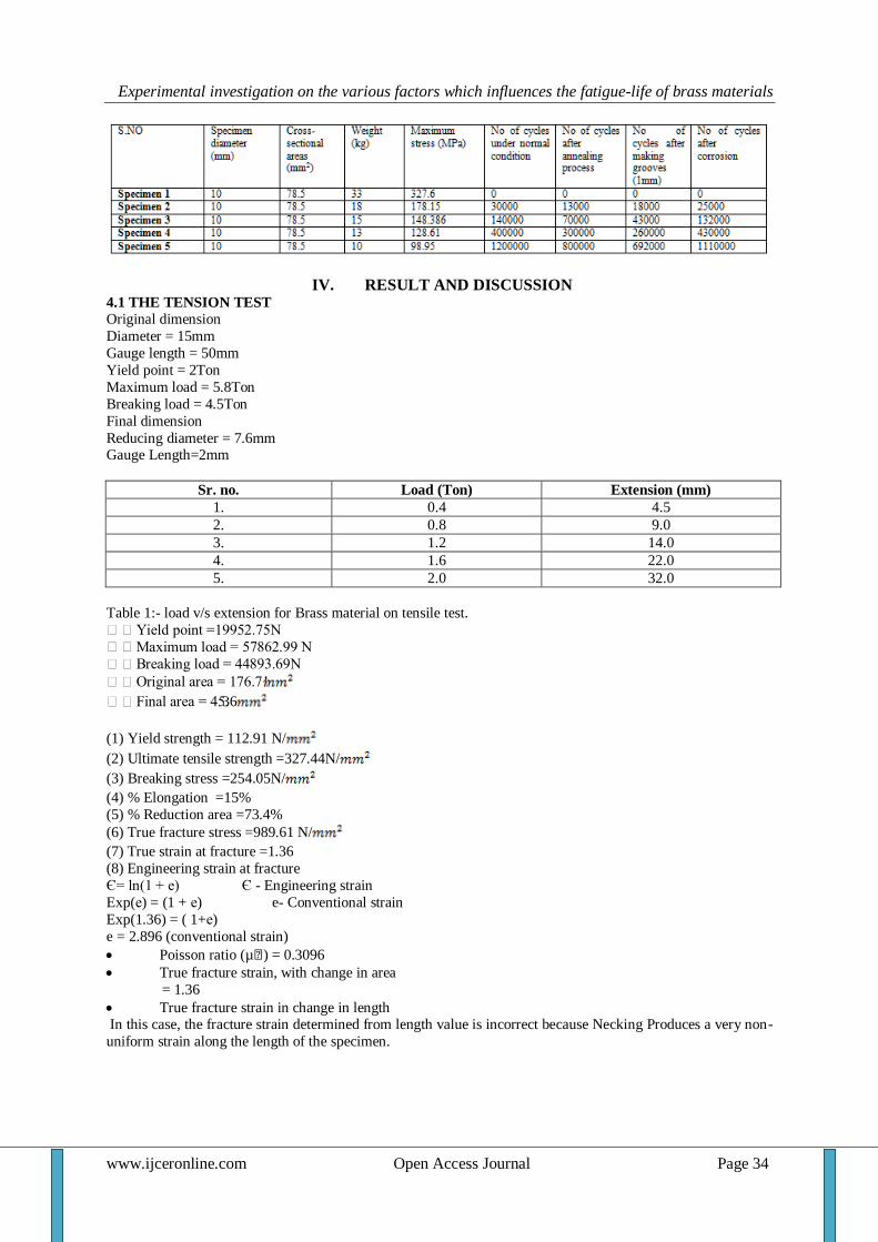
IV. RESULT AND DISCUSSION 4.1 THE TENSION TEST
Original dimension
Diameter = 15mm
Gauge length = 50mm
Yield point = 2Ton
Maximum load = 5.8Ton
Breaking load = 4.5Ton
Final dimension
Reducing diameter = 7.6mm Gauge Length=2mm
Sr. no. Load (Ton) Extension (mm)
1. 0.4 4.5
2. 0.8 9.0
3. 1.2 14.0
4. 1.6 22.0
5. 2.0 32.0
Table 1:- load v/s extension for Brass material on tensile test.
Yield point =19952.75N
Maximum load = 57862.99 N
Breaking load = 44893.69N
Original area = 176.71
Final area = 45.36
(1) Yield strength = 112.91 N/
(2) Ultimate tensile strength =327.44N/
(3) Breaking stress =254.05N/
(4) % Elongation =15%
(5) % Reduction area =73.4%
(6) True fracture stress =989.61 N/
(7) True strain at fracture =1.36
(8) Engineering strain at fracture
Є= ln(1 + е) Є - Engineering strain
Exp(е) = (1 + е) e- Conventional strain
Exp(1.36) = ( 1+е)
e = 2.896 (conventional strain)
Poisson ratio (µ€) = 0.3096
True fracture strain, with change in area
= 1.36
True fracture strain in change in length In this case, the fracture strain determined from length value is incorrect because Necking Produces a very non-
uniform strain along the length of the specimen.

Experimental investigation on the various factors which influences the fatigue-life of brass materials
www.ijceronline.com Open Access Journal Page 35
GRAPH 1 - Relation between LOAD (TON) and EXTENSION (INCH)
4.2 BRINELL HARDNESS TEST DATA
TABLE 2: BRINELL HARDNESS TEST
“D” diameter
of steel ball
(mm).
“d” average
Measured
Diameter
(mm).
“W” is load
on
indenter in
(kg).
BHN NO
10 3.52 1000 99.5
10 4.0 1000 76.3
Where, P = is the applied load (kg).
D =is the diameter of the steel ball (mm).
d =is the diameter of the indentation (mm
(a)P=1000kg, D=10mm, d=3.52mm
=99.5
(b)P=1000kg, D=10mm, d=4.0mm
=76.3
4.3 FATIGUE TEST DATA
Table 3: Fatigue data of Brass specimens
Experimental data from the curve-fitted results were tabulated, and graphs are plotted as follows:-
• Stress v/s No of cycle for general normal condition
• Stress v/s No of cycle for annealed condition
• Stress v/s No of cycle for rough surfaces
• Stress v/s No of cycle for corrosion surfaces
• Stress v/s No of cycle for all conditions The effect of various factors on the fatigue-life of the Brass materials will be investigated with the help of graphs.
GRAPH 2 - Relation between Stress and No of cycles under Normal condition of the specimens Where
N is No of cycles under Normal condition of the specimen under Normal condition of the specimens

Experimental investigation on the various factors which influences the fatigue-life of brass materials
www.ijceronline.com Open Access Journal Page 36
No of cycle (N2) after annealing process
GRAPH 3 - Relation between Stress and No of cycles after Annealing process of the
specimens GRAPH 4 - Relation between Stress and No of cycles after making Grooves on the specimens
Where
N3 is No of cycles after making Grooves on the specimens
GRAPH 5 - Relation between Stress and No of cycles under Normal condition and after Annealing process
condition
Where
N is No of cycles under Normal condition
N2 is No of cycles after Annealing process condition

Experimental investigation on the various factors which influences the fatigue-life of brass materials
www.ijceronline.com Open Access Journal Page 37
GRAPH 6 - Relation between Stress and No of cycles under Normal condition and after making Groove on the
specimens
Where
N is No of cycles under Normal condition N3 is No of cycles after making Groove on the specimens
GRAPH 7 - Relation between Stress and No of cycles under Normal condition and after Corrosion of the
specimens
Where N is No of cycles under Normal condition
N3 is No of cycles after making Corrosion of the specimens
GRAPH 8 - Relation between Stress and No of cycles effects of various factors on the fatigue life of the Brass
materials
Experimental investigation on the various factors which influences the fatigue-life of brass materials
www.ijceronline.com Open Access Journal Page 38
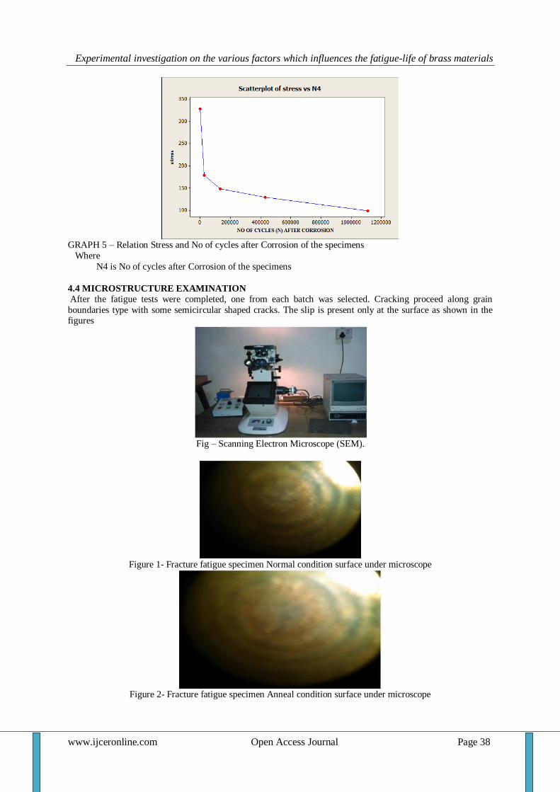
GRAPH 5 – Relation Stress and No of cycles after Corrosion of the specimens
Where
N4 is No of cycles after Corrosion of the specimens
4.4 MICROSTRUCTURE EXAMINATION
After the fatigue tests were completed, one from each batch was selected. Cracking proceed along grain
boundaries type with some semicircular shaped cracks. The slip is present only at the surface as shown in the figures
Fig – Scanning Electron Microscope (SEM).
Figure 1- Fracture fatigue specimen Normal condition surface under microscope
Figure 2- Fracture fatigue specimen Anneal condition surface under microscope
Experimental investigation on the various factors which influences the fatigue-life of brass materials
www.ijceronline.com Open Access Journal Page 39
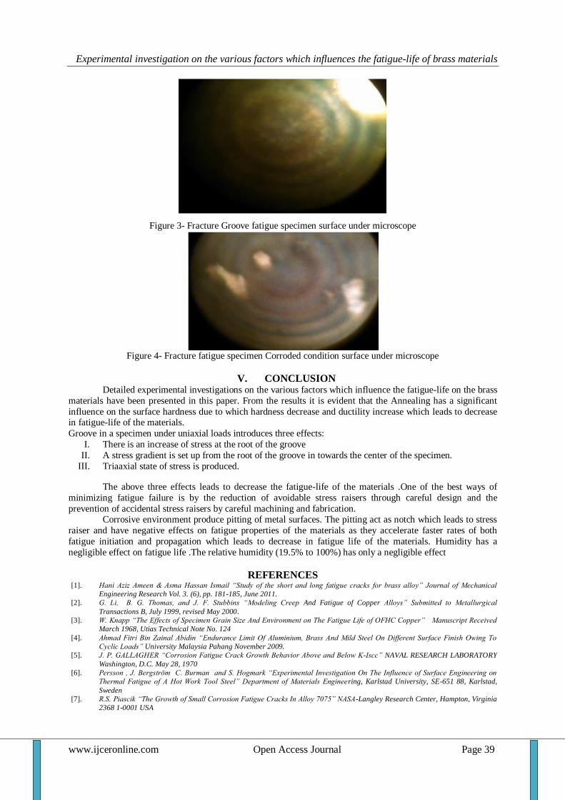
Figure 3- Fracture Groove fatigue specimen surface under microscope
Figure 4- Fracture fatigue specimen Corroded condition surface under microscope
V. CONCLUSION Detailed experimental investigations on the various factors which influence the fatigue-life on the brass
materials have been presented in this paper. From the results it is evident that the Annealing has a significant
influence on the surface hardness due to which hardness decrease and ductility increase which leads to decrease in fatigue-life of the materials.
Groove in a specimen under uniaxial loads introduces three effects:
I. There is an increase of stress at the root of the groove
II. A stress gradient is set up from the root of the groove in towards the center of the specimen.
III. Triaaxial state of stress is produced.
The above three effects leads to decrease the fatigue-life of the materials .One of the best ways of
minimizing fatigue failure is by the reduction of avoidable stress raisers through careful design and the
prevention of accidental stress raisers by careful machining and fabrication. Corrosive environment produce pitting of metal surfaces. The pitting act as notch which leads to stress
raiser and have negative effects on fatigue properties of the materials as they accelerate faster rates of both
fatigue initiation and propagation which leads to decrease in fatigue life of the materials. Humidity has a
negligible effect on fatigue life .The relative humidity (19.5% to 100%) has only a negligible effect
REFERENCES [1]. Hani Aziz Ameen & Asma Hassan Ismail “Study of the short and long fatigue cracks for brass alloy” Journal of Mechanical
Engineering Research Vol. 3. (6), pp. 181-185, June 2011.
[2]. G. Li, B. G. Thomas, and J. F. Stubbins “Modeling Creep And Fatigue of Copper Alloys” Submitted to Metallurgical
Transactions B, July 1999, revised May 2000.
[3]. W. Knapp “The Effects of Specimen Grain Size And Environment on The Fatigue Life of OFHC Copper” Manuscript Received
March 1968, Utias Technical Note No. 124
[4]. Ahmad Fitri Bin Zainal Abidin “Endurance Limit Of Aluminium, Brass And Mild Steel On Different Surface Finish Owing To
Cyclic Loads” University Malaysia Pahang November 2009.
[5]. J. P. GALLAGHER “Corrosion Fatigue Crack Growth Behavior Above and Below K-Iscc” NAVAL RESEARCH LABORATORY
Washington, D.C. May 28, 1970
[6]. Persson , J. Bergström C. Burman and S. Hogmark “Experimental Investigation On The Influence of Surface Engineering on
Thermal Fatigue of A Hot Work Tool Steel” Department of Materials Engineering, Karlstad University, SE-651 88, Karlstad,
Sweden
[7]. R.S. Piascik “The Growth of Small Corrosion Fatigue Cracks In Alloy 7075” NASA-Langley Research Center, Hampton, Virginia
2368 1-0001 USA