experimental studies on heat transfer augmentation...
TRANSCRIPT

i
EXPERIMENTAL STUDIES ON HEAT TRANSFER AUGMENTATION
FOR FLOW OF LIQUID THROUGH CIRCULAR TUBES USING
TWISTED GI WIRES WITH AND WITHOUT BAFFLES AS INSERT
A Thesis submitted in partial fulfilment of the requirements for the degree of
Bachelor of Technology
in
Chemical Engineering
by
Dhanush P
(ROLL NO-110CH0468)
Under the Guidance
of
Prof. S. K. Agarwal
Department of Chemical Engineering
National Institute of Technology
Rourkela
2014

ii
National Institute of Technology
Rourkela
CERTIFICATE
This is to ensure that the theory entitled, "EXPERIMENTAL STUDIES ON HEAT
TRANSFER AUGMENTATION FOR FLOW OF LIQUID THROUGH CIRCULAR
TUBES USING TWISTED GI WIRES WITH AND WITHOUT BAFFLES AS
INSERT" presented by Dhanush P in partial fulfilments for the necessities for the grant of
Bachelor of Technology Degree in Chemical Engineering at National Institute of
Technology, Rourkela (Deemed University) is a bona fide work did by him under my
supervision and direction.
To the best of my knowledge, the matter exemplified in this proposal has not been submitted
to whatever available University/ Institute for the honour of any Degree or Diploma.
Date: 12/05/2014 ___________________
Prof.S.K.Agarwal
Dept .of Chemical Engineering
National Institute of Technology
Rourkela – 769008

iii
ACKNOWLEDGEMENT
I express my deepest thankfulness and earnest appreciation to Prof. S. K. Agarwal for his
valuable guidance, useful feedback and auspicious proposals throughout the whole term of
this venture work, without which this work might not have been conceivable.
I am additionally grateful to Prof. R.K Singh and Prof. H.M Jena (Project organizers) for
their valuable guidance.
I might additionally want to thank Mr. S Majhi & Mr. S Mohanty (TA) for their assistance in
the research laboratory. I also thank other staff parts of my area of expertise for their precious
help and guidance.
Furthermore I also wish to thank Mr. Sarthak subudhi (B.tech Student) and Miss. Tulika
Rastogi (B.tech Student) for his/her tenacious backing and guidance throughout the project.
Date: 12/05/14 ___________________
Dhanush P
(110CH0468)

iv
ABSTRACT
This project deals with the use of twisted GI wires as passive heat transfer augmentation
device. Effect of twisted GI wires without baffles and with baffles, with varying baffle
spacing, was studied experimentally in a double pipe heat exchanger. Effect of insert with
three different baffle spacing (24cm, 12cm, 6cm) were studied. The effect of turbulence
created by twisted wires & baffles on Nusselt number was compared with that of smooth
tube. Based on constant flow rate, the nusselt numbers were found to be 1.23-1.42, 1.32-1.5
&1.49-1.65 times the smooth tube values for baffle spacing of 24cm, 12cm and 6cm
respectively. Based on increase in nusselt number and performance evaluation of inserts with
different baffle spacing, it was concluded that insert with baffle spacing 6cm performs much
better than the inserts with baffle spacing 12cm or 24cm or without baffles.
Continuous research is going on to improve its effectiveness by increasing fluid turbulence,
generating secondary flow patterns, reducing the thermal resistance and increasing the heat
transfer surface area.

v
CONTENTS
Chapter Topic Page No.
Abstract iv
Contents v
List of Figures Vii
List of Tables Viii
Nomenclature ix
Chapter 1 Introduction 1
Chapter 2 Literature Review 3
2.1 Classification of augmentation techniques 4
2.2 Performance evaluation criteria 6
2.3 Twisted tape in laminar flow 8
Chapter 3 Present experimental work 10
3.1 Specifications of Heat exchanger used 11
3.2 Types of Inserts used 11
3.3 Fabrication of inserts 13
3.4 Experimental Setup 14
3.5 Experimental Procedure 17
3.6 Standard equations used 19
3.7 Precautions 20
Chapter 4 Sample calculations 21
4.1 Rotameter calibration 22
4.2 Nusselt number calculations 22
Chapter 5 Results & Discussion 25
5.1 Nusselt number results 26
Conclusion 33

vi
Scope for future work 35
References 36
Appendix 39

vii
List of Figures
FIG NO: FIGURE NAME PAGE NO.
3.1 Twisted GI wires. (Insert without baffle) 12
3.2 Insert with baffle spacing 6cm 12
3.3 Insert with baffle spacing 12 cm 12
3.4 Insert with baffle spacing 24cm 12
3.5 Spinner and Baffles 14
3.6 Experimental setup 15
3.7 Photograph of the experimental setup 16
3.8 Wilson chart 18
4.1 Temperature in different RTD's 22
4.2 Prandtl Number vs. Temperature 24
5.1 Nui vs Re for Smooth Tube 26
5.2 Nusselt number with insert (without baffles) 27
5.3 Insert with baffle spacing 6cm 28
5.4 Insert with baffle spacing 12cm 29
5.5 Insert with baffle spacing 24cm 30
5.6 Comparison of all inserts Nusselt numbers 31
5.7 Performance evaluation criteria, R1 vs. Reynolds Number 32

viii
List of Tables
TABLE
NO: TABLE NAME PAGE NO
2.1 Performance Evaluation Criteria 7
2.2 Performance Evaluation Criteria of Bergles et.al 8
A.1.1 Rotameter calibration 38
A.1.2 RTD Calibration 38
A.2.1 Smooth tube 39
A.2.2 Insert without baffles 39
A.2.3 Insert with baffles and baffle spacing 6cm 40
A.2.4 Insert with baffles and baffle spacing 12cm 40
A.2.5 Insert with baffles and baffle spacing 24cm 41

ix
NOMENCLATURE
Ai Heat transfer area,
Cp Specific heat of fluid, J/Kg.K
di ID of inside tube, m
do OD of inside tube, m
f Fanning friction factor, Dimensionless
fa Friction factor for the tube with inserts,
fo Theoretical friction factor for smooth tube
g acceleration due to gravity, m/
Gz Graetz Number, Dimensionless
Nu Nusselt number
Nui Experimental Nusselt number for smooth tute
Nuo Theoretical Nusselt number for smooth tube
Nua Nusselt number with insert
L heat exchanger length, m
LMTD Log mean temperature difference, °C
M Mass flow rate, kg/sec
Baffle spacing
Pr Prandtl number, dimensionless
Q Heat transfer rate, W
Re Reynolds Number, Dimensionless
R1 Performance evaluation criteria based on constant flow rate
Ui Overall heat transfer coefficient based on inside surface area, W/ °C
k Thermal conductivity, W/m °C

x
Greek letters
Δh Height difference in manometer, m
ΔP Pressure difference across heat exchanger, N/
μ Viscosity of the fluid, N s/
μb Viscosity of fluid at bulk temperature, N s/
μw Viscosity of fluid at wall temperature, N s/
ρ Density of the fluid, kg/

1
CHAPTER 1
INTRODUCTION

2
INTRODUCTION
The process of improvement of heat transfer performance is referred to as heat transfer
enhancement (or augmentation or intensification). These days, research is continuing for new
enhancing heat transfer systems between surfaces and the surrounding liquid. Because of this,
Bergles categorised the mechanisms of enhancing heat transfer as active or passive
techniques. Those which require outside power to keep up the enhancement system are
named active methods. The passive enhancement techniques are those which don't require
outside power to support the enhancements qualities. Illustrations of passive enhancing
methods are: (a) treated surfaces, (b) rough surfaces, (c) extended surfaces, (d) displaced
enhancement devices, (e) swirl flow devices, (f) coiled tubes, (g) surface tension devices, (h)
added substances for liquids, and numerous others. Enhancement procedures basically
diminish the thermal resistance in a conventional heat exchanger by pushing higher
convective heat transfer coefficient with or without surface increments. Subsequently, size of
the heat exchanger could be diminished or the pumping force requirements might be lessened
or the exchanger's operating approach temperature difference might be diminished.
Utilization of Heat transfer enhancement methods lead to increase in Nusselt number
however at the expense of increment in pressure drop. In this way, while planning a heat
exchanger utilizing any of these techniques, examination of heat transfer rate & pressure drop
must be carried out. Separated from this, issues like long term performance & detailed
economic analysis of heat exchanger must be carried out. To accomplish high heat transfer
rate in a current or new heat exchanger while dealing with the increased pumping power, a
few systems have been proposed as of late and are examined in the accompanying segments.
Insert of twisted wires - a type of passive heat transfer augmentation techniques have shown
significantly good results in past studies. For experimental work, twisted GI wires having
diameter around 1.2mm are used. Effect of insert on Nusselt number was studied without
baffles and with baffles ( 24cm or 12cm or 6cm).

3
Chapter 2
LITERATURE REVIEW

4
2.1 CLASIFICATION OF ENHANCEMENT TECHNIQUES: [1, 2]
Heat transfer enhancement or augmentation techniques refer to the improvement of
thermohydraulic performance of heat exchangers. Existing enhancement techniques can be
broadly classified into three different categories:
1. Passive Techniques
2. Active Techniques
3. Compound Techniques
1. PASSIVE TECHNIQUES: These techniques generally use surface or geometrical
modifications to the flow channel by incorporating inserts or additional devices. They
promote higher heat transfer coefficients by disturbing or altering the existing flow behaviour
(except for extended surfaces) which also leads to increase in the pressure drop. In case of
extended surfaces, effective heat transfer area on the side of the extended surface is increased.
Passive techniques hold the advantage over the active techniques as they do not require any
direct input of external power. Heat transfer augmentation by these techniques can be
achieved by using:
Treated Surfaces: This technique involves using pits, cavities or scratches like
alteration in the surfaces of the heat transfer area which may be continuous or discontinuous.
They are primarily used for boiling and condensing duties.
Rough surfaces: These surface modifications particularly create the disturbance in the
viscous sub-layer region. These techniques are applicable primarily in single phase turbulent
flows.
Extended surfaces: Plain fins are one of the earliest types of extended surfaces used
extensively in many heat exchangers. Finned surfaces have become very popular now a days
owing to their ability to disturb the flow field apart from increasing heat transfer area.
Displaced enhancement devices: These inserts are used primarily in confined forced
convection. They improve heat transfer indirectly at the heat exchange surface by displacing
the fluid from the heated or cooled surface of the duct with bulk fluid from the core flow.
Swirl flow devices: They produce swirl flow or secondary circulation on the axial flow
in a channel. Helical twisted tape, twisted ducts & various forms of altered (tangential to
axial direction) are common examples of swirl flow devices. They can be used for both single
phase and two-phase flows.

5
Coiled tubes: In these devices secondary flows or vortices are generated due to
curvature of the coils which promotes higher heat transfer coefficient in single phase flows
and in most regions of boiling. This leads to relatively more compact heat exchangers.
Surface tension devices: These devices direct and improve the flow of liquid to boiling
surfaces and from condensing surfaces. Examples include wicking or grooved surfaces.
Additives for liquids: This technique involves addition of solid particles, soluble trace
additives and gas bubbles added to the liquids to reduce the drag resistance in case of single
phase flows. In case of boiling systems, trace additives are added to reduce the surface
tension of the liquids.
2. ACTIVE TECHNIQUES: These techniques are more complex from the use and design
point of view as the method requires some external power input to cause the desired flow
modification and improvement in the rate of heat transfer. It finds limited application because
of the need of external power in many practical applications. In comparison to the passive
techniques, these techniques have not shown much potential as it is difficult to provide
external power input in many cases. Various active techniques are as follows:
Mechanical Aids: Examples of the mechanical aids include rotating tube exchangers
and scrapped surface heat and mass exchangers. These devices stir the fluid by mechanical
means or by rotating the surface.
Surface vibration: They have been used primarily in single phase flows. A low or high
frequency is applied to facilitate the surface vibrations which results in higher convective
heat transfer coefficients.
Fluid vibration: Instead of applying vibrations to the surface, pulsations are created in
the fluid itself. This kind of vibration enhancement technique is employed for single phase
flows.
Electrostatic fields: Electrostatic field like electric or magnetic fields or a combination
of the two from DC or AC sources is applied in heat exchanger systems which induces
greater bulk mixing, force convection or electromagnetic pumping to enhance heat transfer.
This technique is applicable in heat transfer process involving dielectric fluids.
Injection: In this technique, same or other fluid is injected into the main bulk fluid
through a porous heat transfer interface or upstream of the heat transfer section. This
technique is used for single phase heat transfer process.
Suction: This technique is used for both two phase heat transfer and single phase heat
transfer process. Two phase nucleate boiling involves the vapour removal through a porous

6
heated surface whereas in single phase flows fluid is withdrawn through the porous heated
surface.
Jet impingement: This technique is applicable for both two phase and single phase heat
transfer processes. In this method, fluid is heated or cooled perpendicularly or obliquely to
the heat transfer surface.
3. COMPOUND TECHNIQUES: A compound augmentation technique is the one where
more than one of the above mentioned techniques is used in combination with the purpose of
further improving the thermo-hydraulic performance of a heat exchanger.
2.2 PERFORMANCE EVALUATION CRITERIA: [1] In most practical applications of enhancement techniques, the following performance
objectives, along with a set of operating constraints and conditions, are usually considered for
optimizing the use of a heat exchanger:
1. Increase the heat duty of an existing heat exchanger without altering the pumping power
(or pressure drop) or flow rate requirements.
2. Reduce the approach temperature difference between the two heat-exchanging fluid
streams for a specified heat load and size of exchanger.
3. Reduce the size or heat transfer surface area requirements for a specified heat duty and
pressure drop or pumping power.
4. Reduce the process stream’s pumping power requirements for a given heat load and
exchanger surface area.
It may be noted that objective 1 accounts for increase in heat transfer rate, objective 2 and
4 yield savings in operating (or energy) costs, and objective 3 leads to material savings and
reduced capital costs.
Different Criteria used for evaluating the performance of a single phase flow are:
Fixed Geometry (FG) Criteria: The area of flow cross-section (N and di) and tube length
L are kept constant. This criterion is typically applicable for retrofitting the smooth tubes of
an existing exchanger with enhanced tubes, thereby maintaining the same basic geometry and
size (N, di, L). The objectives then could be to increase the heat load Q for the same approach
temperature ΔTi and mass flow rate m or pumping power P; or decrease ΔTi or P for fixed Q
and m or P; or reduce P for fixed Q.
Fixed Number (FN) Criteria - The flow cross sectional area (N and di) is kept constant,
and the heat exchanger length is allowed to vary. Here the objectives are to seek a reduction
in either the heat transfer area (A L) or the pumping power P for a fixed heat load.

7
Variable Geometry (VN) Criteria - The flow frontal area (N and L) is kept constant, but
their diameter can change. A heat exchanger is often sized to meet a specified heat duty Q for
a fixed process fluid flow rate m. Because the tube side velocity reduces in such cases so as to
accommodate the higher friction losses in the enhanced surface tubes, it becomes necessary
to increase the flow area to maintain constant m. This is usually accomplished by using a
greater number of parallel flow circuits.
Case Geometry M P Q ΔTi Objective
FG-1a N, L, Di X X Q↑
FG-1b N, L, Di X X ΔTi↓
FG-2a N, L, Di X X Q↑
FG-1b N, L, Di X X Δ Ti↓
FG-3 N, L, Di X X P↓
FN-1 N, Di X X X L↓
FN-2 N, Di X X X L↓
FN-3 N, Di X X X P↓
VG-1 --- X X X X (NL) ↓
VG-2a N, L X X X Q↑
VG-2b N, L X X X Δ Ti↓
VG-3 N, L X X X P↓
Table 1: Performance Evaluation Criteria [1]

8
Bergles et al [3] suggested a set of eight (R1-R8) number of performance evaluation criteria
as shown in Table 2.
Criterion number
R1 R2. R3 R4 R5 R6 R7 R8
Basic Geometry × × × ×
Flow Rate × × ×
Pressure Drop × × ×
Pumping Power ×
Heat Duty × × × × ×
Increase Heat
Transfer
× × ×
Reduce pumping
power
×
Reduce
ExchangeSize
× × × ×
Table 2: Performance Evaluation Criteria of Bergles et al [3]
2.3 TWISTED TAPE IN LAMINAR FLOW: [4]
A summary of important investigations of twisted tape in a laminar flow is represented in
Table 3. Twisted tape increases the heat transfer coefficient with an increase in the pressure
drop. Different configurations of twisted tapes, like full-length twisted tape, short length
twisted tape, full length twisted tape with varying pitch, reduced width twisted tape and
regularly spaced twisted tape have been studied widely by many researchers. Use of twisted
tapes for augmentation can be dated back to as early as up to the end of nineteenth century.
One of the early researches on heat transfer enhancement by means of twisted tapes was
carried out by Whitman, [5]. Saha et al. [6] concluded that the short length twisted tapes
perform better than the full length twisted tapes because the swirl generated by the short
length twisted tape decays slowly downstream which increases the heat transfer coefficient
with minimum pressure drop. Regularly spaced twisted tape decreases the friction factor and
reduces the heat transfer coefficient but the reduction in heat transfer coefficient is not much
because the spacing of twisted tape disturbs the swirl flow. Date and Singham [7] studied the
heat transfer and friction factor characteristics of fully developed laminar flows in tube

9
containing twisted tape inserts. Laminar viscous liquid flow with uniform heat flow boundary
condition for high prandtl number (appro.730) was investigated by Hong and Bergles [8.
Tariq et al [9] found that twisted tape in a laminar flow was more efficient than internally
threaded tube. Manglik and Bergles [10] developed the correlation between friction factor
and Nusselt number for laminar flows including the swirl parameter.
Saha et al. [11] found that placing twisted tape concentric to the inside tube gives better heat
transfer performance than a twisted tape inserted by a loose fit. Lokanath and Misal [12]
studied twisted tapes in shell and tube heat exchanger for different fluids. Their study
revealed that twisted tapes of tighter twists are expected to give higher overall heat transfer
coefficients. Lokanath [13] investigated the laminar flow experimentally using the tube fitted
with half length tapes. He concluded that half length twisted tapes gives better performance
than full length twisted tapes on the basis of unit pumping power AI-Fahed et al. [14]
investigated that , for high pressure drop and low twist ratio (y = 5.4) and, a loose fit twisted
tape is a better option for the heat exchanger owing to it’s easy installation and removal for
cleaning purposes. For other twist ratios tight fit gives better performance that the loose- fit
twisted tapes. Liao and Xin [15] carried out experimental work on compound heat transfer
enhancement technique with three dimensional internal extended surfaces by using
segmented twisted tape inserts. Results revealed the reduction in the friction factor with small
decrease in Stanton number. The Stanton number is the ratio of heat transfer rate to the
enthalpy difference and gives a measure of the heat transfer coefficient.
Ujhidy et al. [16] proposed a modified dean number for the laminar flow in coils and tubes
containing twisted tapes and helical elements. Dean number compensates for the curvature of
the coiled tubes or helical elements and gives the measure of the magnitude of the secondary
flows. Thermo-hydraulic performance of twisted tape inserts in a large hydraulic diameter
annulus was reported by Suresh Kumar et al., [17].
In laminar flow, the dominant thermal resistance is distributed entirely over the cross section
of the tube. Thus, a twisted tape insert is more effective than other technique as it mixes the
bulk flow.

10
CHAPTER 3
PRESENT
EXPERIMENTAL WORK

11
3.1 SPECIFIACTIONS OF HEAT EXCHANGER USED:
The experimental study on passive heat transfer augmentation using twisted GI wires was
carried on in a double pipe heat exchanger having the specifications as listed below:-
Inner pipe ID = 22mm
Inner pipe OD=25mm
Outer pipe ID =53mm
Outer pipe OD =61mm
Material of construction= Copper
Heat transfer length= 2.43m
Pressure tapping to pressure tapping length = 2.825m
Water at room temperature was allowed to flow through the inner pipe while hot water (set
point 60°C) flowed through the annulus side in the counter current direction.
3.2 TYPES OF INSERTS USED:
In experiment, four different types of twisted GI wires were used. Three GI wires twisted
together to form a rigid pattern. The diameter of each wire was around 1.2mm.
I. Twisted wires of thickness 1.2mm and length 3m was used in the inner pipe of ID
22mm as shown in the Fig 3.1.
II. Insert with baffles of diameter 16mm and baffle spacing 6cm was used in experiment
to create turbulence. The insert pattern was shown in Fig 3.2.
III. Baffles of tin sheet in circular shape, with diameter 16mm, were used with the twisted
wires. A constant distance of 12cm was kept in between two consecutive baffles as
shown in the Fig 3.3.
IV. Tin sheet was cut into circular patterns of diameter 16mm. These circular patterns
were used as baffles to disturb the flow continuously. The baffle spacing is
maintained as 24cm as shown in the Fig 3.4.
The inserts used for the experimental studies were made of twisted GI wires.
The present work deals with finding the rate of heat transfer and Nusselt number for insert
with varying baffle spacing ( =6cm, 12cm, 24cm) and comparing those results with that of
smooth tube and finally finding the heat transfer enhancement in comparison to a smooth
tube on constant flow rate basis (R1).

12
Figure 3. 1 Twisted GI wires. (Insert without baffle)
Figure 3. 2 Insert with baffle spacing 6cm
Figure 3. 3 Insert with baffle spacing 12cm
Figure 3. 4 Insert with baffle spacing 24cm

13
3.3 FABRICATION OF INSERTS:
The inserts used for the experiment are twisted GI wires. While much writing might be found
about passive heat transfer augmentation using twisted tapes as said prior, this kind of insert
is another sort of insert where no such analyses have been carried out accordingly providing
for us sufficient space for trial studies. Three pieces of GI wire of length 3.5m were cut from
the bundle of GI wire. One end of the each one wire was fixed to window grill very closely.
And other ends of the wires were fixed at the center of the spinner. Before pivoting the
spinner, verify that each of the three wires are straight and uniform. Now apply moderate
rotatory movement by turning the spinner. Drag the spinner towards you while turning, so
that twisting will be uniform. Initially the back pressure will be high, however as the time
proceeds, back pressure will decrease and curving gets troublesome. At the point when back
pressure gets zero, quit twisting and untie the closures of the wires from the window grill and
spinner. The end parts of the fabricated wires were cut in such a way that the length of the
insert becomes 2.95m, which was sufficient for the heat exchanger. To keep the insert at the
middle of the tube, we have used supports. These are of GI wire of length 20mm fixed to the
insert using thin GI wire and fevikwik.
The baffles used as a part of this experiment were of tin sheet. We used sheets from tin boxes,
which are used for storing and transportation of cooking oils. Firstly we had cut the container
into sheets and after that we have cleaned these sheets to remove the oily film covering the
surface of the tin. Then we have marked circular shapes and square shapes with marker on
the tin sheets. The diameter of the circular baffle, we have checked, is 16mm and that of
square is 15mm long. The marked patterns were cut into unique fragments using cutting
machine. After this, a hole was made at the center of each baffle using driller. The diameter
of the opening we made was 5mm. A slit was made in baffles from the edge to the central
point of the baffle to fit it into the insert. As the thickness of the tin sheet is less, slit was
made using a scissor. We used chalk for marking purpose and there after the marked space
were fitted with baffles. Using glue baffles were fitted to the insert at baffle spacing 6cm.
After each one set of experiments, baffles were tested for their location and refitted to their
unique position. After completing experiments with 6cm baffle spacing, every baffle placed
at even position was removed to make baffle spacing 12cm. In the same way baffles were
removed to get a baffle spacing of 24 cm.

14
Figure 3. 5 Spinner and Baffles
3.4 EXPERIMENTAL SETUP:
Fig 3.6 shows the schematic outline of the experimental setup. It is a double pipe heat
exchanger comprising of a calming section, test section, rotameters, overhead water tank for
supplying cold water & a steady temperature bath (500 liter limit) for supplying hot water
with in-built heater, pump & the control system. The test area is a smooth copper tube with
measurements of 2430mm length, Inner tube-22mm ID, and 25mm OD; Outer pipe-53mm
ID, and 61 mm. The external pipe is insulated using 15mm measurement asbestos rope to
lessen heat losses to the air. The rotameter with the flow ranges 300 to 1250 LPH is used to
measure the flow of cold water. The water, at room temperature is drawn from an overhead
tank using gravity flow. There are two rotameters, 1 for hot water flow measuring and
another for the cold water. There is an overhead cold water tank i.e. wellspring of cold water.
We were also fortunate to be outfitted with the modern RTD meter. They have four separate
sensors arranged at different locations to give four temperature T1, T2, T3, T4.
Hot water flow rate was kept steady at 1000 kg/hr. throughout the trial. There is a U Tube
manometer for the pressure drop estimation it comprise of two appendages decently
associated with the two points in the internal pipe. Two pressure tapings- One simply before
the test section and the other simply after the test section are joined to the U-tube manometer

15
for pressure drop estimation. Carbon tetrachloride is used as the manometric liquid. Bromine
crystals were dissolved in it to grant pink color to it for simple identification.
Figure 3. 6 Schematic Diagram for the experimental setup

16
Figure 3. 7 Photograph of the experimental setup

17
3.5 EXPERIMENTAL PROCEDURE:
1. All the RTD and Rotameter were calibrated first.
I. For rotameter calculation, we collected water in the bucket, weighted and
simultaneously time was also noted. Thus mass flow rate was calculated.
II. We repeated this for three times for each particular reading and then took
average of all. The readings are given in A.1.1.
III. For RTD calibration, all the RTDs were simultaneously dipped in the same
water bucket and readings were noted. T1 was made reference & corrections
were made to other RTDs values (i.e. T2-T4) accordingly. The readings are
given in A.1.2.
2. Standardization of the setup:
Before starting the experimental study on friction & heat transfer in heat
Exchanger using inserts, standardization of the experimental setup is done by
obtaining the friction factor & heat transfer results for the smooth tube &
comparing them with the standard equations available.
3. For friction factor determination:
Pressure drop is measured for each flow rate with the help of manometer at room
temperature.
I. The U-tube manometer used carbon tetrachloride as the manometric liquid.
II. Air bubbles were removed from the manometer so that the liquid levels in
both limbs when the flow rate was zero.
III. Water at room temperature is allowed to flow through the inner pipe of the
heat exchanger.
IV. The manometer reading is noted.
4. For Nusselt number calculation:
I. Then, heater is put on to heat the water to 60°C in a constant temperature
water tank of capacity 500 litres. The tank is provided with a centrifugal pump
& a bypass valve for recirculation of hot water to the tank & to the
experimental setup.
II. Hot water at about 60°C is allowed to pass through the annulus side of heat
exchanger at 1000KPH (mh=0.2778 Kg/sec).
III. Cold water is now allowed to pass through the tube side of heat exchanger in
counter current direction at a desired flow rate.

18
IV. The water inlet and outlet temperatures for both hot water & cold water (T1-
T4) are recorded only after temperature of both the fluids attains a constant
value.
V. The procedure was repeated for different cold water flow rates ranging from
0.0927-0.3438 Kg/sec.
5. Preparation of Wilson chart
(3.1)
Where Rd is dirt resistance.
All the resistances, except the first term on the RHS of equation (1), are constant for this set
of experiments.
For Re>10000, Seider Tate equation for smooth tube is of the form:
(3.2)
Therefore Eq. can be written as
(3.3)
Where K is constant.
K is to be found from the Wilson chart (1/Ui vs 1/ ) as the intercept on the y-axis.
K=5.6434× (Refer Fig 3.8).
Figure 3. 8 Wilson chart

19
6. After confirmation of validity of experimental values of Nusselt number in smooth
tube with standard equations, heat transfer studies with inserts were conducted.
7. The heat transfer observations & results for all the cases are presented in Tables
A.2.1-A.2.5.
3.6 STANDARD EQUATIONS USED:
1. Heat transfer calculations
I. Laminar flow:
For Re < 2100,
Nu = f(GZ)
Where GZ =
a. For Gz<100, Hausen Equation is used.
b. For Gz>100, Seider Tate equation is used.
II. Transition zone
For 2100<Re<10000, Hausen equation is used
( )
(
)
III. Turbulent zone
For Re>10000, Seider-Tate equation is used.
Viscosity correction Factor is assumed to be equal to 1 for all calculations as this value for
water in present case will be very close to 1 & the data for wall temperatures is not measured.

20
3.7 PRECAUTIONS
While fabricating twisted wires, precise number of revolutions ought to be measured
for a given twist so different wires could be made of accurate turn degree.
Rotameters ought to be calibrated appropriately to measure definite flow rate of water
for a given rotameter reading.
RTDs ought to be calibrated properly. This is carried out by measuring temperature of
the water bath by all RTDs in the meantime & then taking one of them as reference.
Air bubbles are evacuated from manometer with the goal that fluid levels in both the
limbs are equivalent when the flow is halted. The vicinity of air bubbles in manometer
can prompt incorrect readings because of density difference.
Temperature readings ought to be taken just when the inlet & outlet temperature of
both the fluids achieve a constant value.
21
Chapter 4
SAMPLE CALCULATIONS

22
4.1 ROTAMETER CALIBRATION: (Table A.1.1)
Calculations were made for flow rate of 700 lph.
Observation No.1
Weight of water collected= 12.25 kg
Time= 65sec
m1=0.1900 kg/sec
Observation No.2
Weight of water collected= 12.65kg
Time= 66sec
m2= 0.1917 kg/sec
Observation No.3
Weight of water collected= 11.5 kg
Time= 61sec
m3= 0.1885 kg/sec
=
= 0.1901kg/sec
4.2 NUSSELT NUMBER CALCULATIONS:
For plain tube,
m = 0.1901 (Kg/sec),
A = = 3.14 *0.022*2.43 = 0.16795
52.9
36.1 39.2
49.7 Figure 4. 1 Temperature in different RTD's
T1 = 36.1
T2 = 39.2

23
T3 = 52.9 , T4 = 49.7
= 0.1901* 4186 * (39.2 - 36.1)
= 2466.85 Watt.
= 0.1901 * 4186 * (52.7 – 49.7)
= 2546.43 Watt.
Qavg = 2506.64 Watt
= 49.7 – 36.1 = 13.6
= 52.9 – 39.2 = 13.7
=
= 13.65.
=
= 1093.01 W/
hi can be calculated using,
K is found from the Wilson chart (1/Ui vs. 1/ ) as the intercept on the y-axis.
=
hi(exp) = 2560.39W/
Nui(exp) =
Nui(exp) =
= 8.12.

24
=
= 16360.68.
, where T is
= 4.56.
Figure 4. 2 Prandtl Number vs. Temperature
Theoretical Calculation for smooth tube,
Nuo(th) = 0.023 * * = 89.62
% difference =
* 100
=
* 100
= 0.56
Similarly all the calculations were made using Wilson chart and other standard equations.

25
Chapter 5
RESULTS & DISCUSSION

26
5.1 NUSSELT NUMBER RESULTS:
Table A.2.1-A.2.5 gives the heat transfer results for smooth tube, insert without baffle and
with baffles ( = 6, 12, 24) and also along with the corresponding performance evaluation
criteria R1 for each of the readings. As shown in fig.5.1, the difference between Nui(exp) &
Nuo(th) is very low. With increasing the Reynolds number, Nusselt number for smooth tube
increases. Nui(exp) varies in between 44.18 - 139.69. The percentage difference between
Nui(exp) & Nuo(th) lies in between 9.99 to -3.08.
Figure 5. 1 Nui(exp) vs Re for Smooth Tube
30
300
5000 50000
NU
SSEL
T N
UM
BER
(N
ui)
REYNOLDS NUMBER
Nu i(exp) vs Re -Nui(exp) - Nuo(th)

27
When experiment was carried out with insert (without baffles), nusselt numbers were found
to be higher than that of with the smooth tube. This is due to disturbance created by the insert
in the flow. Nua values ranges from 58.04 – 143.54 and corresponding R1 varies in between
1.12 – 1.34.
Figure 5. 2 Nusselt Number with insert without baffles
30
300
5000 50000
NU
SSEL
T N
UM
BER
(Nu
a)
REYNOLDS NUMBER
Nua vs Re Nua 9 7 7 9
97
- Nua - Nuo(th)

28
Baffles were used along with the insert, with baffle spacing 6cm. The results shows that
nusselt number was increased by considerable amount as compared to that of with the insert.
Nusselt number for this insert lies between 71.46 - 190.96 and corresponding R1 ranges from
1.49 – 1.65. We can see the difference between Nua & Nuo in the Fig 5.3.
Figure 5. 3 Insert with baffle spacing 6cm
30
300
5000 50000
NU
SSEL
T N
UM
BER
(Nu
a)
REYNOLDS NUMBER
Nua vs Re 9
- Nua -Nuo(th) Nua = 1.099* *(

29
Effect of baffles ( ) on Nusselt number can be found in the Fig 5.4. Comparing with
the Fig 5.3, the nusselt numbers were lower in this case. This is mainly due to increase in the
baffle spacing and decreasing the number of baffles. Minimum value of Nua in this case is
64.97 and the maximum value is 171.73. R1 varies from 1.32 to 1.50.
Figure 5. 4 Insert with baffle spacing 12cm
30
300
5000 50000
NU
SSEL
T N
UM
BER
(Nu
a)
REYNOLDS NUMBER
Nua vs Re Nua 9 7 7 9
9
- Nua - Nuo(th)
30
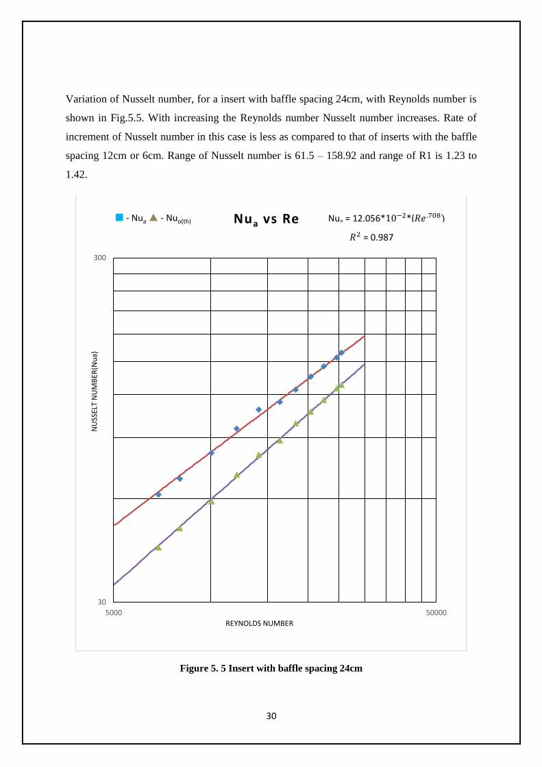
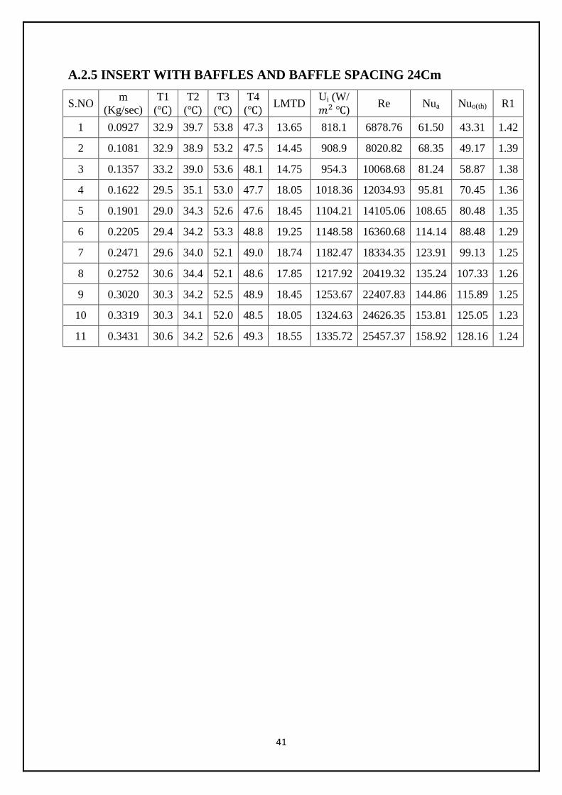
Variation of Nusselt number, for a insert with baffle spacing 24cm, with Reynolds number is
shown in Fig.5.5. With increasing the Reynolds number Nusselt number increases. Rate of
increment of Nusselt number in this case is less as compared to that of inserts with the baffle
spacing 12cm or 6cm. Range of Nusselt number is 61.5 – 158.92 and range of R1 is 1.23 to
1.42.
Figure 5. 5 Insert with baffle spacing 24cm
30
300
5000 50000
NU
SSEL
T N
UM
BER
(Nu
a)
REYNOLDS NUMBER
Nua vs Re - Nua - Nuo(th)
= 0.987
Nua = 12.056* *(

31
General examination of Nusselt numbers of different inserts was indicated in Fig.5.6. Nusselt
number for insert with baffle spacing 6cm is higher than whatever available insert for all
Reynolds numbers. This is predominantly because of turbulence and auxiliary flows created
by the baffles in the flow design. Baffles persistently breaks and forms the boundary layers,
this will builds the Nusselt number. The degree of turbulence created by inserts other than the
insert (with baffle spacing 6cm) was less. So Nusselt number in these cases was low.
Figure 5. 6 Comparison of all inserts Nusselt numbers
30
300
5 0 0 0 5 0 0 0 0
NU
SSEL
T N
UM
BER
REYNOLDS NUMBER
Nu vs Re
Nui(exp) Nua (insert without baffle)
Nua (insert with baffle spacing 24cm) Nua (insert with baffle spacing 12cm)
Nua (Insert with baffle spacing 6cm)

32
Plot for Performance evaluation criteria, R1 (based on constant flow rate) vs. Reynolds
number for different wires is shown in Fig 5.7.
1. Maximum R1 at a given condition is observed for insert with baffle spacing 6cm & then
decreases for 12cm & 24cm baffle spacing. From this we can infer that insert with baffle
spacing 6cm is the best design & is giving better than previously used designs like 12cm and
24cm baffle spacing.
2. Maximum Value of R1 is observed for lowest Reynolds Number & then decreases with
increasing Reynolds Number. This is because as the Reynolds number increases, degree of
turbulence increases in the smooth tube itself as the Reynolds number changes from laminar
to transition to turbulent flow. So when we use an enhancement technique, the relative effect
of enhancement technique (in this case twisted wire) to enhance secondary flow is not that
high. This indicates that such wires are much more effective at lower Reynolds number than
that higher values.
3. R1 varies in between 1.12-1.34, 1.23-1.42, 1.32-1.50 and 1.49-1.65 for insert without
baffles, insert with baffle spacing 24cm, insert with baffle spacing 12cm and insert with
baffle spacing 6cm respectively.
Figure 5. 7 Performance evaluation criteria, R1 vs. Reynolds Number
1
1.1
1.2
1.3
1.4
1.5
1.6
1.7
1.8
1.9
2
0 5000 10000 15000 20000 25000 30000
Per
form
an
ce c
rit
eria
(R
1)
Reynolds number
R1 vs Re
R1 (insert without baffle) R1 ( Insert with baffle spacing 24cm)
R1 ( insert baffle spacing 12cm) R1 ( insert baffle spacing 6cm)
33
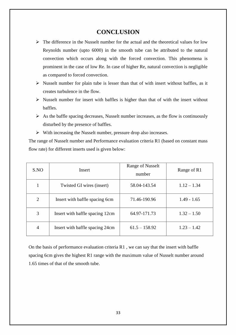
CONCLUSION
The difference in the Nusselt number for the actual and the theoretical values for low
Reynolds number (upto 6000) in the smooth tube can be attributed to the natural
convection which occurs along with the forced convection. This phenomena is
prominent in the case of low Re. In case of higher Re, natural convection is negligible
as compared to forced convection.
Nusselt number for plain tube is lesser than that of with insert without baffles, as it
creates turbulence in the flow.
Nusselt number for insert with baffles is higher than that of with the insert without
baffles.
As the baffle spacing decreases, Nusselt number increases, as the flow is continuously
disturbed by the presence of baffles.
With increasing the Nusselt number, pressure drop also increases.
The range of Nusselt number and Performance evaluation criteria R1 (based on constant mass
flow rate) for different inserts used is given below:
S.NO Insert Range of Nusselt
number Range of R1
1 Twisted GI wires (insert) 58.04-143.54 1.12 – 1.34
2 Insert with baffle spacing 6cm 71.46-190.96 1.49 - 1.65
3 Insert with baffle spacing 12cm 64.97-171.73 1.32 – 1.50
4 Insert with baffle spacing 24cm 61.5 – 158.92 1.23 – 1.42
On the basis of performance evaluation criteria R1 , we can say that the insert with baffle
spacing 6cm gives the highest R1 range with the maximum value of Nusselt number around
1.65 times of that of the smooth tube.

34
In a heat exchanger, while the inserts could be used to improve the Nusselt number, they
additionally acquire an increment in the pressure drop. At the point when the pressure drop
increases, the pumping force cost additionally builds, consequently expanding the working
expense. Since we need to keep the working expense to a base, there must be a proper
balance between the Nusselt number and the pressure drop. While there is a requirement for
the Nusselt number to be increased, the pressure drop can't be permitted to go beyond a
certain specified limit.
So relying upon the prerequisite, one of the above mentioned inserts might be used for heat
transfer augmentation.

35
SCOPE FOR FUTURE WORK
Further adjustment is possible using this study as base. Some of the conceivable outcomes are
said underneath:
Distance between two successive (baffle spacing) could be varied and their impact on
Nusselt number can be noted down.
Experimental work can be done at low Reynolds number using viscous fluids, as the
inserts have demonstrated relatively better results at low Reynolds number.
Pressure drop is a huge loss of this modification so studies could be made to minimize
the pressure drop.
Design of baffle are also a subject to influence the Nusselt number.
Geometry of baffles:
1. Circular baffles rather than rectangular baffles could be used.
2. Baffles could be kept at an angle to flow of fluid as instead of putting perpendicular to
flow of fluid.
3. Size of baffles might be varied.
The same experiment can also be tested with cooling operations.

36
REFERENCES:
1. B.Adrian and K. Allan D. Heat transfer enhancement. In Heat Transfer Handbook, Chapter
14, pg.1033, -1101, Wiley-interscience, 2003.
2. Bergles, A.E. -Techniques to augment heat transfer.‖ In Handbook of Heat Transfer
Applications (Ed.W.M. Rosenhow), 1985, Ch.3 (McGraw-Hill, New York).
3. Bergles, A.E. and Blumenkrantz, A.R. -Performance evaluation criteria for enhanced heat
transfer surfaces‖. Proc. Of 5th Int. Heat Conf., Tokyo, Vol 2, 239-243(1974)
4. A. Dewan, P. Mahanta, K Sumithraju, P. Suresh kumar - Review of passive heat transfer
augmentation techniques. Proc. Institution of Mechanical Engineers Vol. 218 Part A (2004):
Journal of Power and Energy.
5. Whitham, J. M. The effects of retarders in fire tubes of steam boilers. Street Railway.
1896, 12(6), 374.
6. Saha, S. K. and Dutta, A. -Thermo-hydraulic study of laminar swirl flow through a circular
tube fitted with twisted tapes. Trans. ASME, J. Heat Transfer, 2001, 123, 417–421.
7. Date, A. W. and Singham, J. R. Numerical prediction of friction and heat transfer
characteristics of fully developed laminar flow in tubes containing twisted tapes. Trans.
ASME, J. Heat Transfer, 1972, 17, 72.
8. Hong, S. W. and Bergles, A. E. Augmentation of laminar flow heat transfer in tubes by
means of twisted-tape inserts.Trans. ASME J. Heat Transfer, 1976, 98, 251–256.
9. Tariq, A., Kant, K. and Panigrahi, P. K. Heat transfer enhancement using an internally
threaded tube. In Proceedings of 4th ISHMT–ASME Heat and Mass Transfer Conference,
India, 2000, pp. 277–281 (Tata McGraw-Hill, New Delhi).
10. Manglik, R. M. and Bergles, A. E. ―Heat transfer and pressure drop correlations for
twisted tape insert in isothermal tubes. Part 1: laminar flows. Trans. ASME, J. Heat
Transfer, 1993, 116, 881–889.
11. Saha, S. K., Dutta, A. and Dhal, S. K. Friction and heat transfer characteristics of laminar
swirl flow through a circular tube fitted with regularly spaced twisted-tape elements. Int.J.
Heat and Mass Transfer, 2001, 44, 4211–4223
12. Lokanath, M. S. and Misal, R. D. An experimental study on the performance of plate heat
exchanger and an augmented shell and tube heat exchanger for different types of fluids for
marine applications. In Proceedings of 5th ISHMT– ASME Heat and Mass
Transfer Conference, India, 2002, pp. 863–868 (Tata McGraw-Hill, New Delhi).

37
13. Lokanath, M. S. - Performance evaluation of full length and half length twisted tape
inserts on laminar flow heat transfer in tubes‖. In Proceedings of 3rd ISHMT–ASME
Heat and Mass Transfer Conference, India, 1997, pp. 319–324 (Tata McGraw-Hill,
New Delhi).
14. Al-Fahed, S., Chamra, L. M. and Chakroun, W. Pressure drop and heat transfer
comparison for both micro-fin tube and twisted-tape inserts in laminar flow.
Experimental Thermal and Fluid Sci., 1999, 18, 323–333.
15. Q. Liao, M.D. Xin - Augmentation of convective heat transfer inside tubes with three
dimensional internal extended surfaces and twisted-tape inserts’ Chemical Engineering
Journal 78 (2000).
16. Ujhidy et. al, Fluid flow in tubes with helical elements, Chemical Engineering and
Processing 42 (2003), pp. 1–7.
17. Suresh Kumar, P., Mahanta, P. and Dewan, A. Study of laminar flow in a large diameter
annulus with twisted tape inserts. In Proceedings of 2nd International
Conference on Heat Transfer, Fluid Mechanics, and Thermodynamics, Victoria Falls,
Zambia, 2003, paper KP3.
38
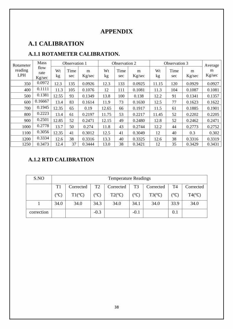
APPENDIX
A.1 CALIBRATION
A.1.1 ROTAMETER CALIBRATION.
Rotameter
reading
LPH
Mass
flow
rate
Kg/sec
Observation 1 Observation 2 Observation 3 Average
m
Kg/sec Wt
kg
Time
sec
m
Kg/sec
Wt
kg
Time
sec
m
Kg/sec
Wt
kg
Time
sec
m
Kg/sec
350 0.0972 12.3 135 0.0926 12.3 133 0.0925 11.15 120 0.0929 0.0927
400 0.1111 11.3 105 0.1076 12 111 0.1081 11.3 104 0.1087 0.1081
500 0.1381 12.55 93 0.1349 13.8 100 0.138 12.2 91 0.1341 0.1357
600 0.16667 13.4 83 0.1614 11.9 73 0.1630 12.5 77 0.1623 0.1622
700 0.1945 12.35 65 0.19 12.65 66 0.1917 11.5 61 0.1885 0.1901
800 0.2223 13.4 61 0.2197 11.75 53 0.2217 11.45 52 0.2202 0.2205
900 0.2501 12.85 52 0.2471 12.15 49 0.2480 12.8 52 0.2462 0.2471
1000 0.2778 13.7 50 0.274 11.8 43 0.2744 12.2 44 0.2773 0.2752
1100 0.3056 12.35 41 0.3012 12.5 41 0.3049 12 40 0.3 0.302
1200 0.3334 12.6 38 0.3316 13.3 40 0.3325 12.6 38 0.3316 0.3319
1250 0.3473 12.4 37 0.3444 13.0 38 0.3421 12 35 0.3429 0.3431
A.1.2 RTD CALIBRATION
S.NO Temperature Readings
T1
(
Corrected
T1(
T2
(
Corrected
T2(
T3
(
Corrected
T3(
T4
(
Corrected
T4(
1 34.0 34.0 34.3 34.0 34.1 34.0 33.9 34.0
correction -0.3 -0.1 0.1

39
A.2 NUSSELT NUMBER CALCULATION RESULTS
A.2.1 SMOOTH TUBE
S.NO m
(Kg/sec)
T1
( T2
( T3
( T4
( LMTD
Ui (W/
) Re Nui(exp) Nuo(th) %diff
1 0.0927 36.1 40.8 52.7 50.9 13.29 752.34 6878.76 44.18 43.31 2.06
2 0.1081 36.0 40.9 53.0 51.3 13.64 785.20 8020.82 47.69 49.17 -3.08
3 0.1357 36.1 40.6 52.3 50.3 12.91 880.44 10068.68 58.28 58.87 -1.06
4 0.1622 36.2 39.9 52.6 50.7 14.05 960.49 12034.93 71.15 70.45 1.01
5 0.1901 36.1 39.2 52.9 49.7 13.65 1093.01 14105.06 89.12 89.62 -0.56
6 0.2205 36.2 39.3 52.7 50.5 13.85 1081.64 16360.68 90.25 88.48 2.01
7 0.2471 34.0 37.2 52.4 49.8 15.50 1151.40 18334.35 105.08 99.13 6.04
8 0.2752 33.5 36.3 52.5 49.8 16.25 1180.20 20419.32 110.55 107.33 2.99
9 0.3020 33.5 35.8 52.9 49.9 16.75 1223.22 22407.83 121.68 115.89 5.01
10 0.3319 32.9 35.0 52.9 49.7 17.34 1281.78 24626.35 137.56 125.05 9.99
11 0.3431 31.7 34.6 53.0 49.8 18.25 1289.07 25457.37 139.69 128.16 8.98
A.2.2 INSERT WITHOUT BAFFLES
S.NO m
(Kg/sec)
T1
( T2
( T3
( T4
( LMTD
Ui (W/
) Re Nua Nuo(th) R1
1 0.0927 33.1 39.5 52.6 50.8 13.28 788.16 6878.76 58.04 43.31 1.34
2 0.1081 33.1 38.7 53.1 50.7 15.95 851.11 8020.82 61.46 49.17 1.25
3 0.1357 33.4 38.8 53.0 50.4 15.56 910.82 10068.68 72.41 58.87 1.23
4 0.1622 29.7 34.9 53.9 50.9 20.08 992.86 12034.93 86.65 70.45 1.23
5 0.1901 29.2 34.1 52.7 49.8 19.58 1067.81 14105.06 95.77 80.48 1.19
6 0.2205 29.6 34.0 52.3 49.4 19.04 1096.41 16360.68 104.41 88.48 1.18
7 0.2471 29.8 33.8 52.8 49.5 19.35 1155.98 18334.35 113.99 99.13 1.15
8 0.2752 30.8 34.2 53.1 49.9 18.99 1186.92 20419.32 124.50 107.33 1.16
9 0.3020 30.5 34.0 52.9 49.5 18.95 1231.19 22407.83 132.11 115.89 1.14
10 0.3319 30.5 33.9 53.0 49.8 19.19 1293.21 24626.35 142.56 125.05 1.14
11 0.3431 30.8 34.0 53.1 49.8 19.05 1306.95 25457.37 143.54 128.16 1.12

40
A.2.3 INSERT WITH BAFFLES AND BAFFLE SPACING 6CM
S.NO m
(Kg/sec)
T1
( T2
( T3
( T4
( LMTD
Ui (W/
) Re Nua Nuo(th) R1
1 0.0927 32.9 39.7 53.8 47.3 13.65 975.34 6878.76 71.46 43.31 1.65
2 0.1081 32.9 38.9 53.2 47.5 14.44 1090.78 8020.82 80.15 49.17 1.63
3 0.1357 33.2 39.0 53.6 48.1 14.75 1195.57 10068.68 94.78 58.87 1.61
4 0.1622 29.5 35.1 53.0 47.7 18.05 1220.57 12034.93 112.72 70.45 1.60
5 0.1901 29.0 34.3 52.6 47.6 18.45 1322.55 14105.06 127.16 80.48 1.58
6 0.2205 29.4 34.2 53.3 48.8 19.24 1327.50 16360.68 139.80 88.48 1.58
7 0.2471 29.6 34.0 52.1 49.0 18.74 1369.15 18334.35 153.65 99.13 1.55
8 0.2752 30.6 34.4 52.1 48.6 17.85 1402.56 20419.32 165.29 107.33 1.54
9 0.3020 30.3 34.2 52.5 48.9 18.45 1479.63 22407.83 177.31 115.89 1.53
10 0.3319 30.3 34.1 52.0 48.5 18.05 1517.98 24626.35 187.58 125.05 1.5
11 0.3431 30.6 34.2 52.6 49.3 18.55 1563.29 25457.37 190.96 128.16 1.49
A.2.4 INSERT WITH BAFFLES AND BSFFLE SPACING 12Cm
S.NO m
(Kg/sec)
T1
( T2
( T3
( T4
( LMTD
Ui (W/
) Re Nua Nuo(th) R1
1 0.0927 32.5 39.5 53.6 51.7 16.52 950.19 6878.76 64.97 43.31 1.50
2 0.1081 32.6 39.2 54.4 52.5 17.44 1025.28 8020.82 72.77 49.17 1.48
3 0.1357 32.7 38.3 53.6 51.6 17.04 1103.37 10068.68 84.77 58.87 1.44
4 0.1622 32.6 38.0 54.5 52.1 17.96 1164.46 12034.93 98.63 70.45 1.40
5 0.1901 32.6 37.3 53.6 51.3 17.47 1216.55 14105.06 111.06 80.48 1.38
6 0.2205 32.8 37.0 54.3 51.8 18.14 1281.01 16360.68 121.22 88.48 1.37
7 0.2471 32.7 36.5 53.4 51.0 17.59 1295.92 18334.35 133.83 99.13 1.35
8 0.2752 32.8 36.5 53.7 51.0 17.70 1337.83 20419.32 144.90 107.33 1.35
9 0.3020 32.8 36.4 54.3 51.3 18.20 1409.74 22407.83 154.13 115.89 1.33
10 0.3319 33.0 36.3 53.8 51.1 17.80 1433.65 24626.35 165.07 125.05 1.32
11 0.3431 33.2 36.3 54.3 51.3 18.05 1507.34 25457.37 171.73 128.16 1.34
41
A.2.5 INSERT WITH BAFFLES AND BAFFLE SPACING 24Cm
S.NO m
(Kg/sec)
T1
( T2
( T3
( T4
( LMTD
Ui (W/
) Re Nua Nuo(th) R1
1 0.0927 32.9 39.7 53.8 47.3 13.65 818.1 6878.76 61.50 43.31 1.42
2 0.1081 32.9 38.9 53.2 47.5 14.45 908.9 8020.82 68.35 49.17 1.39
3 0.1357 33.2 39.0 53.6 48.1 14.75 954.3 10068.68 81.24 58.87 1.38
4 0.1622 29.5 35.1 53.0 47.7 18.05 1018.36 12034.93 95.81 70.45 1.36
5 0.1901 29.0 34.3 52.6 47.6 18.45 1104.21 14105.06 108.65 80.48 1.35
6 0.2205 29.4 34.2 53.3 48.8 19.25 1148.58 16360.68 114.14 88.48 1.29
7 0.2471 29.6 34.0 52.1 49.0 18.74 1182.47 18334.35 123.91 99.13 1.25
8 0.2752 30.6 34.4 52.1 48.6 17.85 1217.92 20419.32 135.24 107.33 1.26
9 0.3020 30.3 34.2 52.5 48.9 18.45 1253.67 22407.83 144.86 115.89 1.25
10 0.3319 30.3 34.1 52.0 48.5 18.05 1324.63 24626.35 153.81 125.05 1.23
11 0.3431 30.6 34.2 52.6 49.3 18.55 1335.72 25457.37 158.92 128.16 1.24