experimental study and design analysis of piles in clay.pdf
TRANSCRIPT

7/22/2019 Experimental Study and Design Analysis of Piles in Clay.pdf
http://slidepdf.com/reader/full/experimental-study-and-design-analysis-of-piles-in-claypdf 1/9
ABSTRACT
The work shows the investigation of compressive and tensile loaded piles insoil. The work shows the experimental testing of piles in clay and specificlaboratorial investigations (which are adjusted to the experiment), as it alsoshows specific design procedures, their compares and value grade. In thedesign procedures the algorithms are set, the bearing capacity terms computeand the programs programmed, and the results compared with theexperimental. Except for the algorithms, specific relations based on manyresults gathered from experimental investigations on drilled piles in clay areused.
KEYWORDS: Keywords: piles, tension piles, analysis, design
INTRODUCTION
There are various values of bearing capacity factors, proposed by various authors, which areused in tip pile bearing capacity design analysis. For example, for the case of undrainedcohesive soil, threw the design the bearing capacity factor that is based on the theory andempirically based on the laboratorial investigation. Some authors assume that the bearingcapacity factor for undrained methods depends of more facts. In this work the theoreticalexploration of the bearing capacity factor for the pile tip in cu and cf soil is shown, and forthe superficial area many experimental explorations, that will also be theoretically defined,
have been gathered. Laboratorial explorations that are adjusted to the experimental are made,so that the bearing design with soils (cohesion and friction angle) and soils . The pile
design in clay with soils is also shown with setting and integrating the shear strength on
Experimental Study and DesignAnalysis of Piles in Clay
Božo Soldo, Ph.D.
Senior Assistant, University of Zagreb, Geotechnical Faculty Varazdin , [email protected]
Krešo Ivandić, Ph.D.
Geokod, d.o.o., Zagreb, [email protected]
Hrvoje Babić
Student, University of Zagreb, Geotechnical Faculty Varazdin , [email protected]
Page 1 of 9ejge paper 2005-0521
10/17/2011http://www.ejge.com/2005/Ppr0521/Ppr0521.htm

7/22/2019 Experimental Study and Design Analysis of Piles in Clay.pdf
http://slidepdf.com/reader/full/experimental-study-and-design-analysis-of-piles-in-claypdf 2/9
slide surfaces. Specific results of visual observations on tested piles will be shown. Thedesign results will be compared with the experimental (measured).
Handling Curvilinear Coordinates
An experiment on piles for determining the pile bearing capacity on the tip and superficial
area, and their relation and other visual occurrences, has been led. The experiment was leadon two piles, one pile was loaded with compressive load and then on tensile load, Figure 1.
The diagram in Figure 2 shows the force an movement relation for all lead examples of piletesting: tensile loaded piles, compressive loaded piles, and tensile loaded piles that have beenpreviously been loaded with compressive load also as the compressive loaded piles that waspreviously loaded with tensile load.
The lines in the upper part of the diagram are the force to movement relations forcompressive loaded piles, and in the lower part are the force to movement relations for tensileloaded piles.
The solid lines show the force to movement relations for undisturbed piles, that were notpreviously tested, and the dashed lines also show the force to movement relations for pilesthat were previously tested on compressive, and then on tensile load.
Figure 1. (a) The pile load scheme, (b) The force to movement relation diagram for all leadtestings of compressive loaded and tensile loaded piles.
The bearing capacity gained on the tensile loaded piles is . The bearing capacity gained onthe tensile loaded piles threw experimental testing is .
Page 2 of 9ejge paper 2005-0521
10/17/2011http://www.ejge.com/2005/Ppr0521/Ppr0521.htm

7/22/2019 Experimental Study and Design Analysis of Piles in Clay.pdf
http://slidepdf.com/reader/full/experimental-study-and-design-analysis-of-piles-in-claypdf 3/9
Figure 2( a). The formed soil on the pile after pulling it out, (b) The post-load condition
The Figure 2 (a) shows that the formed soil on the pile is thicker toward the pile tip, whiletoward the pile head the shear on the pile (concrete) and soil contact occurred.
After pulling out the pile from the soil and digging, the following has been noticed: In the piletip area was the soil that transforms from the condition with less disturbance to the loosecondition as shown on Figure 2 (b), while the other sample has completely differentproperties in the superficial area; its more compact, its not loose while disturbed in differ of the previous one, Figure 2b).
THE LABORATORY SOIL TESTING
In purpose of investigation the pile, laboratorial investigation shown in the continuation havebeen led:
- The undrained clay strength has been tested with the vane shear (diameter 12.7 mm andslope speed ), and after several tested samples it was , therefore the accepter averagevalue was.
- The movement – shear strength ratio testing among the clay and concrete has been led. Thetesting speed for direct shear is approximately equal to the tested piles speed, so that aspecific design for comparison with measured results could be led. The direct shear test speedwas ( 0,5 mm/min.
- The strength parameters were tested on three samples and there average value wasapproximately: cohesion and friction angle .
THE PILE BEARING CAPACITY
The pile bearing capacity c, ( soil.The literature mostly shows the bearing capacity termsusing the so-called bearing factors. An example of shear strength integration on an assumed
Page 3 of 9ejge paper 2005-0521
10/17/2011http://www.ejge.com/2005/Ppr0521/Ppr0521.htm
7/22/2019 Experimental Study and Design Analysis of Piles in Clay.pdf
http://slidepdf.com/reader/full/experimental-study-and-design-analysis-of-piles-in-claypdf 4/9
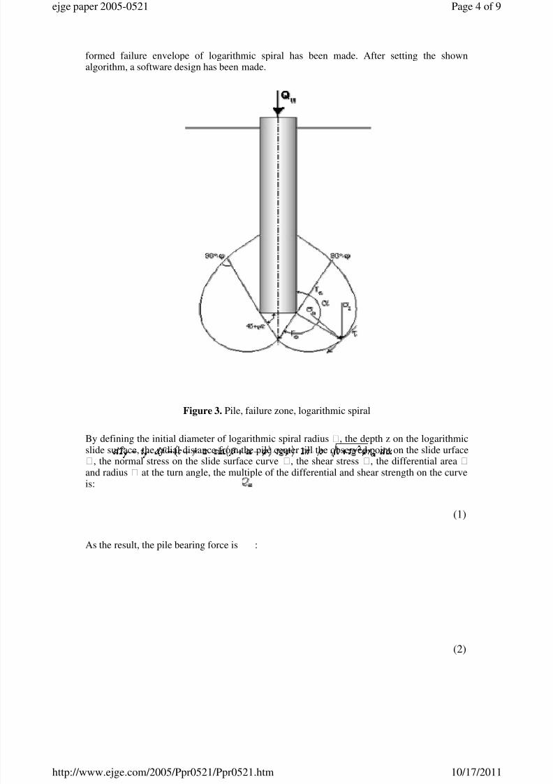
formed failure envelope of logarithmic spiral has been made. After setting the shownalgorithm, a software design has been made.
Figure 3. Pile, failure zone, logarithmic spiral
By defining the initial diameter of logarithmic spiral radius , the depth z on the logarithmicslide surface, the radial distance from the pile center till the observed point on the slide urface, the normal stress on the slide surface curve , the shear stress , the differential area and radius at the turn angle, the multiple of the differential and shear strength on the curveis:
As the result, the pile bearing force is :
(1)
(2)
Page 4 of 9ejge paper 2005-0521
10/17/2011http://www.ejge.com/2005/Ppr0521/Ppr0521.htm

7/22/2019 Experimental Study and Design Analysis of Piles in Clay.pdf
http://slidepdf.com/reader/full/experimental-study-and-design-analysis-of-piles-in-claypdf 5/9
Pile bearing capacity in soil. Bearing capacity the tip. The bearing force on the pile tip is:, wherefore is the bearing pressure on the tip pile, and it depends of the undrainedstrength and bearing capacity .
For example of a case of undrained cohesive soil, bearing factor capacities that are based
on theory and empirically based on laboratorial investigations are gained. Some authorsassume that the Nc coefficient depends of other facts i.e: - the depth diameter ratio L/D(Tavares, 1993.), - the pile diameter D (Robert, 1997.), according to Meyerhof is 5-9 and itdepends of the number of impacts SPT. According to the literature the bearing capacity forclay is from 6 till 13, but usually 9 is used.
Page 5 of 9ejge paper 2005-0521
10/17/2011http://www.ejge.com/2005/Ppr0521/Ppr0521.htm

7/22/2019 Experimental Study and Design Analysis of Piles in Clay.pdf
http://slidepdf.com/reader/full/experimental-study-and-design-analysis-of-piles-in-claypdf 6/9
Figure 4. Pile, assumed failure surface
The design of assumed area where failure takes place:
Assuming that the torus failure surface begins under the pile tip in angle of and ends, that iscloses on the piles superficial area with angle turn of of a full circle. The plan length of thisfailure surface is the piles tip perimeter . Based on this the torus are can be carried out.
The rotation surface area can be carried out (torus):
The total assumed shear according to Figure 4 (b) is . The assumed surface till thehorizontal according to Figure 4 (c) is. According to this, the term for pile tip bearingcapacity can be written:
, till the vertical or assuming that the failure occurs till the horizontal.
The bearing capacity for compressive piles is defined as a sum of the bearing capacity of friction between the pile and soil, that is the superficial area, and the bearing capacity of thepile tip, while the bearing capacity of tensile piles is defined only as the bearing capacity of superficial area.
The superficies bearing capacity. The friction force, that is, the superficies bearing capacity
is:
, wherefore
is the friction among the pile and soil, and depends on the undrainedstrength and correction factor of undrained strength, in literature known as the -method.A factor correction and undrained strength ratio diagram in shown in the Figure 5. Thediagram is composed of experimental investigation literature data. Two curves and formula of
(3)
Page 6 of 9ejge paper 2005-0521
10/17/2011http://www.ejge.com/2005/Ppr0521/Ppr0521.htm

7/22/2019 Experimental Study and Design Analysis of Piles in Clay.pdf
http://slidepdf.com/reader/full/experimental-study-and-design-analysis-of-piles-in-claypdf 7/9
average value data are shown. The average value of the factor correction can be calculatedusing the term.
Figure 5. The factor correction and undrained strength relation
For the shown example, a point of undrained strength and factor correction is shown, whichnoticeably approximately equals to the shown curves that have the term: and , and for the
experimental example the correction factor is .
THE DESIGN AND EXPERIMENTAL RESULTS
The comparison of the bearing capacity design and experiment results
Table 1. The bearing capacity pile results (for the average soil parameters)
Page 7 of 9ejge paper 2005-0521
10/17/2011http://www.ejge.com/2005/Ppr0521/Ppr0521.htm

7/22/2019 Experimental Study and Design Analysis of Piles in Clay.pdf
http://slidepdf.com/reader/full/experimental-study-and-design-analysis-of-piles-in-claypdf 8/9
Note: Beside the conclusion that the results depend of exact laboratorial soil testings, thefollowing can be added. The design has been carried out using the dimensions of theincorporate pile. The gathered design results all minor then the experimental. If the facts thatare noticed after the experiment are used (for example the formed soil on the superficies area,which changes the pile diameter and likewise) that is, the slide surface as shown on Figure 2,more precise results can be gathered comparing to the experimental.
CONCLUSION
The authors showed their work of investigation of compressive and tensile loaded piles inclay. Beside the investigation of the pile bearing capacity of tensile and compressive loadedpiles, visually observed displaces in soil and soil – pile contact, specific conclusions havebeen gathered also as for literature data. For the complicated designs as integration of shearstrength threw the surface failure and others, computer programs have been designed. Afterleading the data through, a comparison of certain conclusions have been led through and othergathered literature data have gathered. For the complicated designs as integration of shearstrength on a certain failure surface, computer programs have been programmed. Afterleading all these data, a comparison of pile bearing capacity has been made: the design resultsand experiment results, and mostly depend of the accuracy of laboratorial investigations of soil parameters, where the parameter soil design relation is shown. The parameter test speedis adjusted to the pile experiment that took place. On this experiment example, the exact
results, also as less sensitive is the undrained strength method, while the soil model withMohr-Columbovim parameters gives a greater sensitivity. Exept for the influence of thelaboratory testes to the design results, it can be added that accurate design results are gatheredby using the observed formations on the experiment, as for example the formed slide surface.The reliability of each method is also notable.
REFERENCES
1. Budhu, M. (1999) "Soil mechanics and foundations," John Wiley & Sons, Inc, NewYork / Chichester / Weinheim / Brisbane / Singapore /Toronto.
2. Bowles, J.E. (1988) "Foundation Analysis and Desing," McGraw-Hill Book Company,New York, U.S.A.
Page 8 of 9ejge paper 2005-0521
10/17/2011http://www.ejge.com/2005/Ppr0521/Ppr0521.htm

7/22/2019 Experimental Study and Design Analysis of Piles in Clay.pdf
http://slidepdf.com/reader/full/experimental-study-and-design-analysis-of-piles-in-claypdf 9/9
3. Coduto, D.P. (1994) "Foundation design, Principles and Practices," A ParamountCommunication Company, Englewood Cliffs, New Jersey.
4. Das, B.M. (1987) "Theoretical foundation engineering," Department of CivilEngineering & Mechanics, Developments in geotechnical engineering 47, Amsterdam-Oxford-new York-Tokyo.
5. Houlsby, G.T. and C.M. Martin (2003) "Undrained bearing capacity factors for conicalfootings on clay," Geotechnique 53, No. 5, pp. 513-520.
6. Kulhawy, F.H. and P.W. Mayne (1990) "Manual on Estimating Soil Properties forFoundation Design," EPRI, Cornel University Ithaca, New York.
7. Kulhawy, F.H., (1990) "Drilled shaft foundations, Edited by Hsai-YangFang,"Foundation enginering handbook, Boston/Dordrecht, London, p.p 537-552.
8. Meyerhof, G.G. (1961) "The Ultimate Bearing Capacity of Wedge-shapedFoundations," Procid. V. ICSMFE, Paris, Vol. II., str. 105-109.
9. Meyerhof, G.G. and J.I. Adams (1968) "The ultimate uplift capacity of Foundation,"Canadian Geotechnical Journal, Vol. V., 225-244.
10. Meyerhof, G.G. (1976) "Bearing Capacity and settlement of pile foundations," TheEleventh Terzaghi Lecture (1975) November 5, Journal of the GeotechnicalEngineering Division, ASCE, 102 (GT3): 195-228.
11. Poulos, H.G. and E.H. Davis (1990) "Pile foundation analysis and design," Robert E.Krieger publishing comany, Malabar, Florida.
12. Robert, Y. (1997) "A few comments on pile design," Canadian Geotechnical Journal -
34, Canada, pp 560-567.
13. Thasnanipan, N., G. Baskaran and M.A. Anvar (1998) "Effect of construction time andbetonite vicosity on capacity of bored piles," Deep foundations on Bored and AugerPiles, Van Impe & Haegeman, Balkema, Rotterdam, bap III., p.p. 171-177.
14. Tavares, A.X. (1993) "Bearing capacity of bored piles in overconsolidated clay," VanImpe W.F.: Deep foundations on bored and auger piles - BAP II - Proc. of the 2nd Int.Geotech. Seminar, Gent, 1-4 June, Rotterdam, Balkema, pp. 391-394.
© 2005 ejge
Page 9 of 9ejge paper 2005-0521