experimental study of an integral catalytic combustor ... · shown in the figure. combustion air is...
TRANSCRIPT

II III IIIIII IIII II IIII III111 I111 III1 I1II III 111I 111I 1111111111I111 3 1176 00159 9969
, , I. .
DOE/NASA/51 040-36 NASA TM-82783
ASA-TM-8278319820010817
Experimental Study of an Integral Catalytic CombustorHeat Exchanger for Stirling Engines
Daniel L. Bulzan National Aeronautics and Space Administration Lewis Research Center
Work performed for U.S. DEPARTMENT OF ENERGY Conservation and Renewable Energy Office of Vehicle and Engine R&D
; y I ~p q 1982
Prepared for
LANGLEY RrS~ARrH ,eNTER LIBRARY, NASA
HAfl.1PTON. VIRGINIA
1982 International Congress and Exposition sponsored by the Society of Automotive Engineers Detroit, Michigan, February 22-26, 1982
https://ntrs.nasa.gov/search.jsp?R=19820010817 2019-05-07T07:59:14+00:00Z

b
NOTICE
This report was prepared to document work sponsored by the United States Government Neither the Un ited States nor ItS agent. the United Stales Department of Energy . nor any Federa l employees . nor any of their contractors. subcontractors or their employees. makes any warranty. express or Implied . or assumes any legal liability or responsl Dti lty for the accuracy. complet eness. or usefu lness of any tnformatlon . apparatus . product or proce9S disclosed . or represents that ItS use would not tnfrtnge pri vate ly owned rights
" 'J l

I '
Experimental Study of an
DOEINASAI 1040-36 NASA TM-82783
Integral Catalytic CombustorHeat Exchanger for Stirling Engines
Daniel L. Bulzan National Aeronautics and Space Administration Lewis Research Center Cleveland, Ohio 44135
Work performed for U.S. DEPARTMENT OF ENERGY Conservation and Renewable Energy Off ice of Vehicle and Engine R&D Washington, D.C. 20545 Under Interagency Agreement DE-AI01-77CS51 040
1982 International Congress and Exposition sponsored by the Society of Automotive Engineers Detroit, Michigan, February 22-26, 1982

ABSTRACT
An experimental study was conducted to determine the feasibility of using catalytic combustion with heat removal for the Stirling engine to reduce exhaust emissions and also improve heat transfer to the working fluid. The study was conducted using spaced parallel plates. An internally air-cooled heat exchanger was placed between two noble metal catal ytic plates. A preheated fuel-air mixture passed between the plates and reacted on the surface of the catalyzed plates. Heat was removed from the catalytic surface by radiation and convection to the air-cooled heat exchangers to control temperature and minimize thermal NOx emissions. The study was conducted at inlet combustion air temperatures from 850 to 900 K, inlet velocities of about 10 m/s, equivalence ratigs from 0.5 to 0.9 and pressures from 1.3x10 to 2 .0x10~ Pa. Propane fuel was used for all testing. Combustion efficiencies greater than 99.5 percent were measured. NOx emissions ranged from 1.7 to 3.3 g N02/kg fuel. The results demonstrate the feasibility of the concept and indicate that further investigation of the concept is warranted.
1
AS PART OF THE STIRLING ENGINE Highway Vehicle Systems Project, Lewis Research Center is currently considering catalytic combustion as a potential low-emissions concept for the Stirling engine. The present study was performed to evaluate one catalytic combustor configuration at Stirling engine conditions to determine if catalytic combustion might offer emission or heat transfer advantages over conventional combustion systems.
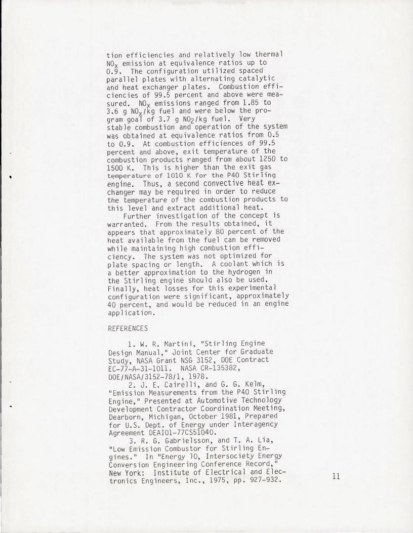
A cross-section of the P40 Stirling engine is shown in Fig. l(a). The engine operates on the thermodynamic cycle of isothermal compression and expansion and constant volume heating and cooling. The working fluid, usually hydrogen, is heated, cooled, expanded, and compressed at the appropriate times in the cylinders to move the pistons and drive the engine. The working fluid is moved from the hot end of the cylinder, through the heater tubes, where heat is received from the combustion products, into the regenerator, where heat is given up and stored, then through a cooler, where it is cooled, and finally enters the cold end or lower portion of the cylinder. As the piston moves down, the working fluid is pumped back through the cooler, regenerator and heater tubes into the hot end of the engine where it expands and pushes the piston down. As the piston moves up, the cycle is repeated. A complete description of the Stirling cycle can be found in Ref. 1. A schematic diagram of the conventional combustion system used for the P40 Stirling engine is presented in Fig. l(b) (2). Average temperatures are shown in the figure. Combustion air is supplied by a blower. The air passes through a preheater where it is heated to approximatel y 1000 K and then enters the combustor . Fuel is injected through an air-assist fuel injector and combustion takes place at equivalence ratios ranging from 0.6 to 0.9 . The combustion products pass over two banks of heater tubes through which the working fluid is flowing. Heater tube wall temperature is held constant at about 1000 K. After passing over the heater tubes, the combustion products exit through the preheater where their sensible heat is used to preheat the inlet
*Numbers in parentheses designate Reference s at end of paper. 2

air. The Stirling engine is inherently a producer of high NOx emissions because of the near stoichiometric conditions in the combustor. To meet automotive NO x standards, exhaust gas recirculation is used (2-4). As shown in Fig. l(b), it ranges f r om 30 to 90 percent of the inlet air flowrate . Hi gher engine cycle efficiencies require hi gher working fluid temperatures (1) . Thi s may necessitate increased levels of Exhaust Gas Recirculation in order to meet NOx em i ssion standards.
Catalytic combustion is being consider ed as an alternative to the previously descr ibed conventional system. Catalytic combust ion wi th heat removal has the potential of combining the combustor and heater tubes into an integral unit. Catalytic combustion with heat removal may offer several advantages over a conventional combustion system. Catalytic combustion is capable of reactin g fuel-air mixtures at lower combustion temperatures than would otherwise be possible (S- 6). With an integral catalytic combustor/heat exchanger, heat can be removed fr om the system as combustion is occurring which will reduce flame temperatures and minimize the formation of thermal NOx emissions.
Catalytic combustion with heat removal has been successfully tested for application to watertube boilers (7). A configuration utilizing two concentric tubes with air cool ing of the center tube and combustion of a fuel-air mixture in the annulus has also been successfully tested. Combustion efficienc ies greater than 99.S percent and NO x emission s less than 2 parts per million were obtained (8) •
For the present study, an experimental evaluation was conducted for a configuration that used the radiation-cooled concept of Ref. 8. It consisted of a series of spaced parallel plates. Each plate was 10.2 cm long and 10.2 cm high. An air-cooled heat exchanger plate was placed between two cata lyst coated plates. Tests were conducted at inl et air temperatureg up to 900 K, pressures of 1. 3x10S to 2xlO Pa, and a range of equivalence ratios from O.S to 0.9. Prop ane fuel was used for all tests. Inlet and ex it t emperature of the cooling air and combust ion mixture were measured. Heat exchanger pl ate wall temperatures were also measured. Combus tion products were sampled and concentra- 3
tions of C02, CO , NOx, and unburned hydrocarbons were measured .
EXPERIMENTAL DETAILS
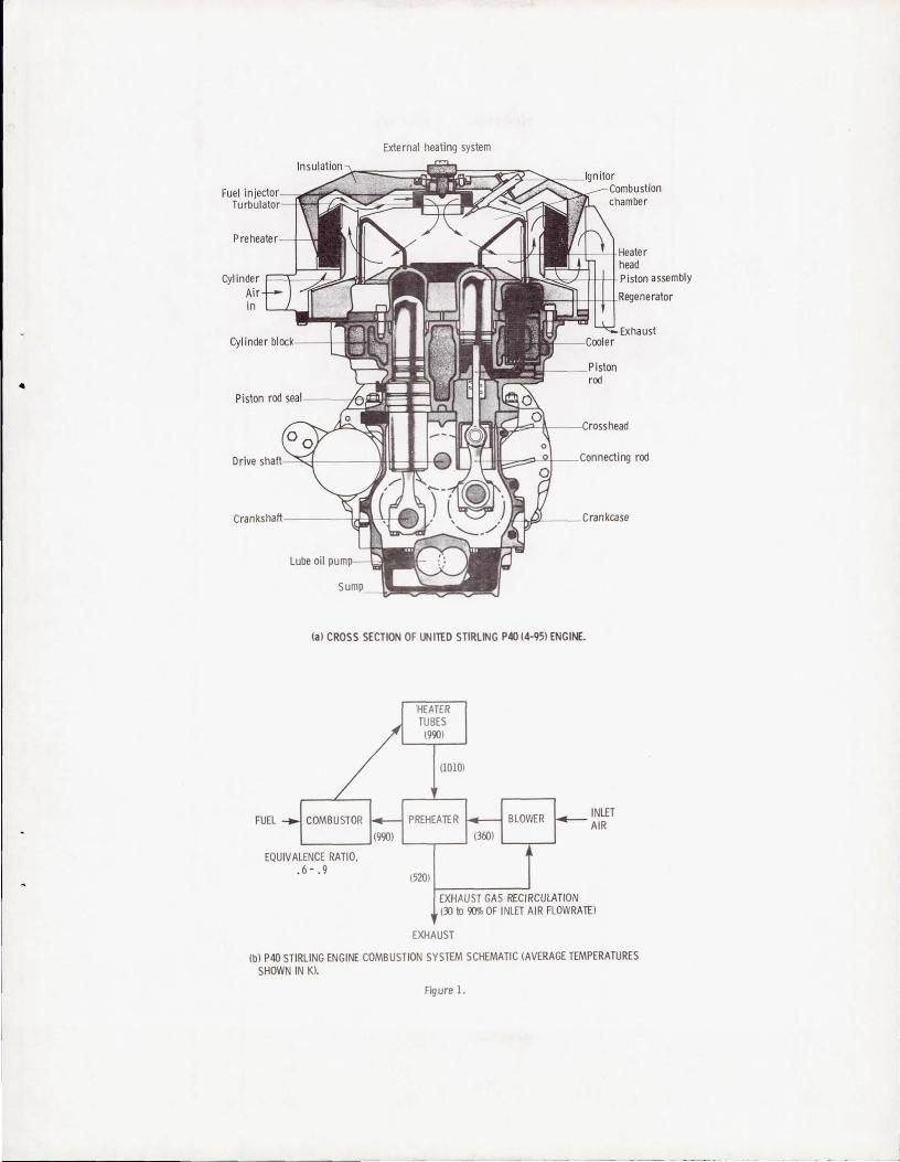
The test section simu lated a segment of a possible Stirling engine heater head design . Figure 2(a) is a schematic drawing of the test rig used for this study. The test section was constructed of 0.64 cm thick stainless steel plate welded into a rectangular , 12.4 by 15.2 cm inside dimensions, test section. The test section was internally insul ated with castable insulation to minimize heat los ses. Inlet combustion air was indirectly preheated and entered the test section at temperatures up to 900 K. Inlet air ' temperature was measured with a single Chromel/Alumel thermocouple. located at the centerline 6.35 cm upstream of the catalytic and heat exchanger plates . All temperatures were measured with Chromel/Alume l thermocouples. The combustion air flowed through two mUllite honeycomb monolith flow straightness. Both monoliths had 0.318 cm round holes. For the second monolith placed directly upstream of the catalytic and heat exchanger plates, all holes were blocked with ceramic cement except those alligned with the rectangular passages between the plates.
Gaseous propane fuel was injected through s ixteen, 0.03 cm inside diameter tubes which were placed inside the open passages of the flow straightener and equally spaced. The tubes were placed in two rows of 8 tubes to inject fuel into each of two rectangular passages. All fuel tubes were the same length, 25.4 cm, to provide equal flowrates through each tube and obtain a uniform fuelair mixture for the catalytic plates.
The catalytic and heat exchanger plates were located directly downstream of the fuel inj ector as shown in Fig. 2(a). Figure 2(b) is a drawing of the plate configuration tes ted. The configuration consisted of three spaced parallel plates. A heat exchanger pl ate was placed btween two catalytic plates. Plate spacing of 0. 318 cm was maintai ned by ceramic rods inserted between the plates. The preheated fuel-air mixture flowed through the two passages between the plates and reacted on the surface of the catalytic plates. For some cases, combustion gas temperature was measured at two axial 4

locations in each passage. Castable insulation, not shown in Fig. 2(b), completely encased the plate assembly to insulate and also prevent bypassing of the flow around the plates.
Figure 3 is a drawing of the heat exchanger plate. It was 0.64 cm thick. It was internally air-cooled with the cooling air making 8 passes through the plate. Cooling air passages with rectangular cross sections of 0.91 by 0.32 cm. were machined in the plate. The heat exchanger plate was constructed of Hastelloy-X. Cooling air entered and exited the heat exchanger plate as shown in Fig. 3. Wall temperatures were measured with shielded thermocouples attached to the outside walls.
The catalytic plates were made from sintered silicon carbide with an alumina washcoat to which a noble metal catalyst was applied. Catalytic plate length and height was the same as the heat exchanger plate, 10.2 by 10.2 cm. Plate thickness was 0.318 cm.
Combustion products exit temperature was measured 3.5 cm downstream of the catalytic and heat exchanger plates with two thermocouples located approximately 0.2 cm from each side wall. A water-cooled stainless steel gas sampling probe was used to obtain a continuous sample for emissions measurements 10.17 cm downstream of the plates at the rig centerline. The gas sample line was heated to prevent unburned hydrocarbons from condensing. Concentrations of CO and C02 were measured with nondispersive infrared analyzers, unburned hydrocarbons with a flame ionization detector and nitrogen oxides (total NO + N02) with a chemiluminescent analyzer. A manual back pressure valve was used to control rig pressure. Combustion and cooling air flowrates were measured with calibrated 0.254 cm diameter orifices. Gaseous propane fuel flowrates were measured with a calibrated 0.051 cm diameter orifice.
MEASUREMENTS AND COMPUTATIONS
INLET VELOCITY - Inlet velocity was calculated using the air and fuel mass flowrates, inlet air temperature, inlet pressure, and the cross-sectional flow area between the plates. 5
EMISSION INDEX - Emissions were measured as concentratiops in ppm by volume, corrected for water of combustion, and converted to emission indices using the expressions in Ref. 9.
COMBUSTION EFFICIENCY - Combustion efficiency was calculated from the expression,
EFF = 100 - 0.1 [E.IHC - E.I.HC,EQJ
where
EFF E. 1. x
HV x
[ HVCO ]
- 0.1 HV [E.I· CO - E.I· CO EQJ FUEL '
combustion efficiency, percent emission index of specie x,
gx/kg fuel net heating value of specie X, J/kg
Equilibrium values, E.I. x eq at the average measured exit temperature were calculated using the computer program of Ref. 10.
HEAT FLUX - Heat flux to the cooling air was calculated using the measured cooling air mass flowrate, the temperature difference between the inlet and exit, and an average constant pressure specific heat at the average cooling air temperature.
RESULTS AND DISCUSSION
EMISSIONS - The effect of equivalence ratio on NO x emssions is presented in Fig. 4. NO x emissions are presented as an emission index, g N02/kg fuel for equivalence ratios ranging from 0.55 to 0.90. NOx emissions ranged from 1.7 to 3.3 g N02/k9 fuel. Data are presented for three combustion air flowrates at inlet air temperatures from 850 to 900 K. Pressure ranged from 1.3x10S Pa at 2.8 g/s to 2.0x10S Pa at 5.1 g/s. The program NO x emission goal of 3.7 g N02/k9 fuel is shown for comparison. It is based on a proposed standard of 0.4 g NOx/mile and was calculated using the density of diesel no. 2 fuel and a steady state fuel economy of 30 miles/gallon. All measured NOx emissions are below the program goal. From Fig. 4, the NO x emission index decreased with equivalence ratio. NO x concentration levels in parts per 6

•
million increased slightly with equivalence ratio. Data are shown for cooling air flowrates of 3.5 and 5.9 g/s. At a constant cooling air flowrate, NO x emissions increased as the combustion air flowrate increased. Less heat was removed as a percentage of that available at the increased combustion air flowrates and the temperature of the system increased. This would be expected to increase NOx emissions. Pressure was also increased at the increased combustion air flowrates which would also tend to increase NO x emissions. Little effect of cooling air flowrate, however, was shown on NOx emissions at a combustion air flowrate of 2.8 g/s. For this combustion air flowrate, at an equivalence ratio of 0.88, cooling air flowrates of 5.9 and 3.5 g/s produced exit temperatures of 1352 and 1420 K, respectively. Little measureable difference in NO , emissions would be expected at these relatively low temperatures for a difference of 68 K.
The effect of equivalence ratio on CO emissions is presented in Fig. 5. CO emissions are presented as an emission index, g CO/kg fuel, for equivalence ratios ranging from 0.55 to 90. Data are presented for the identical flowrates as in Fig. 4. A CO emission program goal of 32.0 g CO/kg fuel is shown for comparison. It is based on a proposed standard of 3.4 g CO/mile and was again calculated using the density of diesel no. 2 fuel and a fuel economy of 30 miles/gallon. The CO emission index ranged from 0.3 to 2."7 g CO/kg fuel and was well below the program goal. CO emissions generally decreased with equivalence ratio until about 0.75 or 0.8 and then increased. For a constant cooling air flowrate of 5.9 gIs, CO emissions decreased with increasing combustion air flowrate. At the higher combustion air flowrate, system temperatures were increased and pressure was also slightly higher, both of which tend to increase reaction rates and reduce CO emissions. At a combustion air flowrate of 2.8 gIs, little effect of cooling air flowrate is shown at an equivalence ratio of 0.88, however, a small effect is shown at an equivalence ratio of 0.75. This could be attributed to data scatter at these very small values since there is a difference of only 20 ppm. Calculated equilibrium values of CO at the average exit temperature ranged 7

:------------ -
from about 1x10⁻³ to 2x10⁻² g CO /kg fuel for the equivalence ratios and exit temperatures of this study. Equilibrium CO increased with both equiva lence ratio and ex it temperature. Even though measured CO emissions were above the equilibrium values, they were still very low. Combustion efficiencies greater than 99.5 percent were measured for all data points shown in Fig. 5.
No data are presented for unburned hydrocarbons emissons. They were extremely low at the f air ly high inlet air temperatures used for this study for combustion products exit temper atures greater than approximately 1250 K. At exit temperatures below 1250 K, combustion efficiency decreased rapidly and unburn ed hydrocarbons emissions increased .
Axial temperature profile of the system is presented in Fig. 6. Temperatures of the combustion gas, heat exchanger plate, and cooling air are shown for a combustion air flowrate of 2.8 g/s and an equivalence rat io of 0.9. The combustion efficiency was 99 .88 percent. Combustion gas temperatures are shown for both flow passages. As shown in Fig. 6, the inlet air temperature was 900 K. At a distance 2.5 cm downstream of the leading edge of the plates, the average combustion gas temperature in the passages was 1200 K. The combustion gas temperature increased to an average of 1435 K at a dis tance 7.5 cm downstream of the plate inlet. The temperature of the combustion products remained essentially constant from 7.5 cm downstream to the measured exit temperature at 13.5 cm downstream. Heat exchanger plate wall temperature increased linearly from 1090 K at 1.2 cm downstream to 1165 K at 8.7 cm from the leading edge. Cooling air temperatures, measured only at the inlet and ex it, were 290 and 880 K, respective ly. The larger temperature difference between the heat exchanger plate wall and the cooling air as compared to the combustion gas and the heat exchanger plate wall indicates that the cooli ng air heat transfer coefficient is small er than the combustion side coeffic ient and was the limiting heat transfer coeff icient fo r this case.
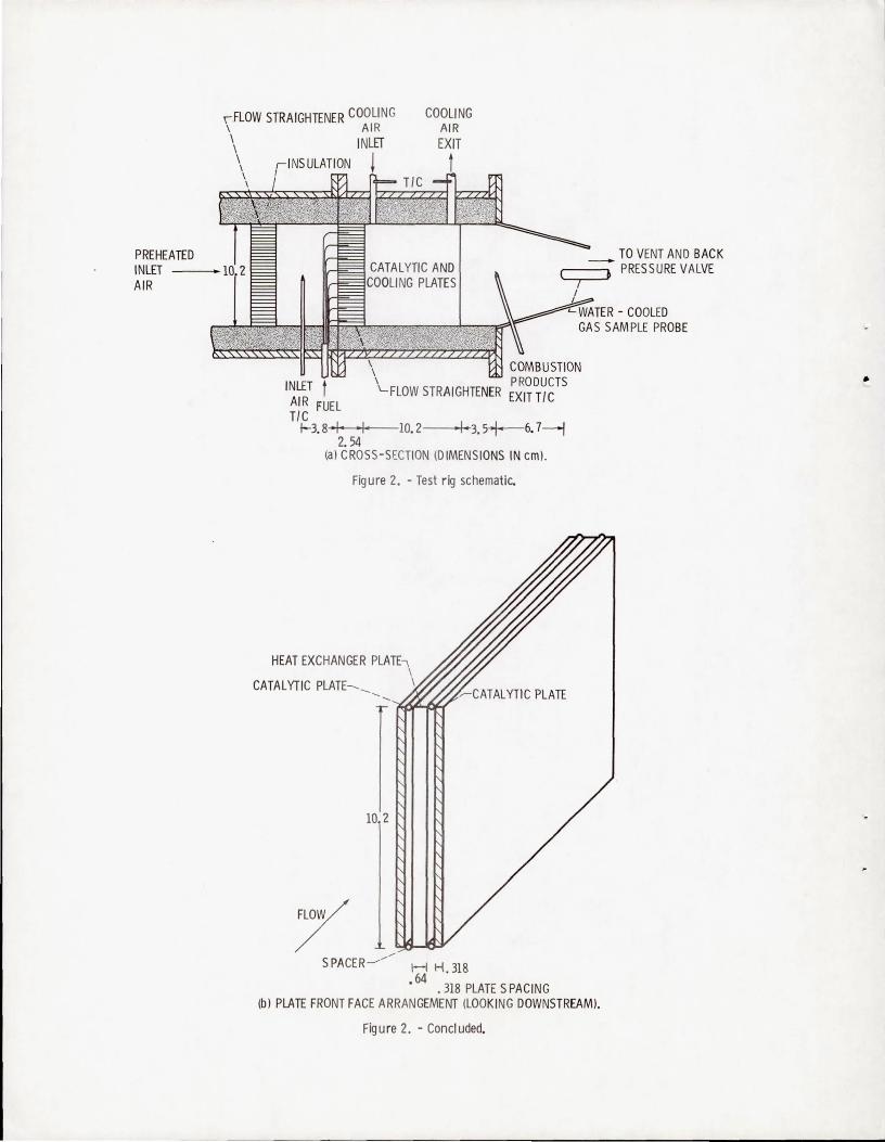
HEAT FLUX - Heat flux~ as a function of the fuel flowrate in W/cm , is presented in Fig. 7. The parameter is based on the side exposed heat exchanger plate surface area ,
•
8
206.5 crrf. Data are shown for three combustion air flowrates at inlet air temperatures from ~50 to 900~. Pressure ranged from 1.3x10 to 2.0x10 Pa. The cooling air flowrate was held constant at 5 .9 g/ s. Heat flux available from the fuel is shown . As shown in Fig. 7, heat flux to the cooling air ranged from about 11 to 15 W/cm2• At a fuel flowrate of 0.1 gis, 44 percent of the heat available from the fuel was transferred to the cooling air. Another 20 percent of the heat available from the fuel remained in the combustion products. Heat flux to the combustion products was based on the increase in combustion gas temperature from the inlet to the exit and does not include the sensib le preheat of the combustion air. About 40 percent of the heat available from the fuel was lost from the system as heat losses. More insulation would decrease this loss. However, at the relatively low flowrates used for this study, heat losses are expected to remain fairly large. In an engine application, a configuration utilizing this concept would probably consist of a circular arrangement of alternating heat exchanger and catalytic plates and heat losses could be kept to a minimum, since the heat loss from the side would be eliminated.
For this study, the heat exchanger plate wall temperature was maintained at approximately the heater tube temperature of the P40 Stirling engine, 1000 - 1200 K. The P40 Stirling engine uses high pressure hydrogen as the working fluid which has a very high convective heat transfer coefficient. The bulk temperature of the hydrogen is only a few degrees less than the heater tube wall temperature. Utilizing hydrogen as a coolant in the heat exchanger plates could increase the heat transferred to the coolant. It would be necessary, however, to design the system such that the wall temperature be kept at current levels. Too much heat cannot be extracted, however, or the combustion reactions will be quenched and poor combustion efficiencies will result. If gas phase reactions in the passages are not initiated, which quickly completes the combustion reactions, and only surface reactions are occurring on the catalytic surface, combustion efficiency will be relatively poor since no t enough surface area is available for comple te conversion of the fuel. If heat losses cou ld 9

be eli minated and that heat tran sf erred to the coolant, about 80 percent of t he heat av ailabl e fr om the fuel coul d be tr ansferred t o the cool an t at a fuel f lowr ate of 0.1 g/s . Since combustion ef ficiency was greater than 99.5 percent for all points shown in Fig . 7, combustion eff iciency could be maintained at this level s ince total heat removed from the combustion r eactions woul d be un ch anged . As previous ly di scussed, the exit t emperature of the combus tion products must be approximately 1250 K or above, t o maintain combustion efficiences of at least 99 .5 percent.
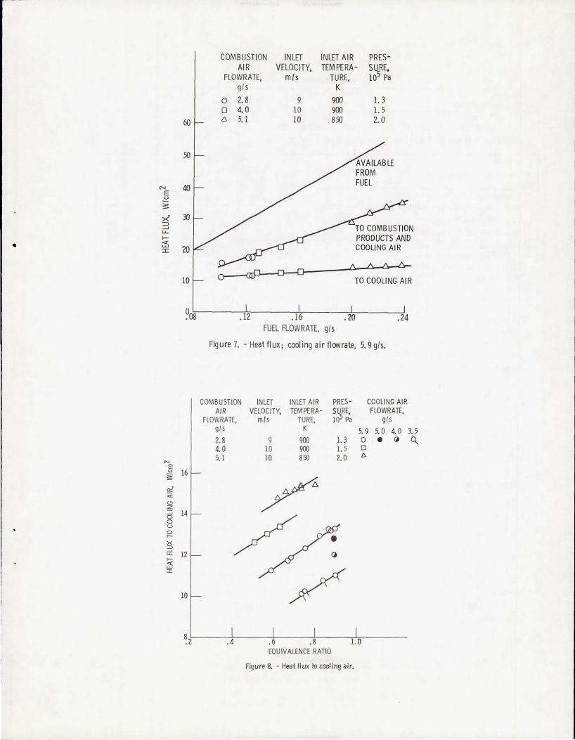
Heat flux to the cooling air as a fun cti on of the equivalence ratio i s presented i n Fig. 8. Heat flux in W/cm2 , based on 206.5 cm2 of heat exchanger surface area, is presented for equivalence ratios ranging from 0.5 to 0.9. At a cooling air flowr ate of 5. 9 gIs, data are presented fo r three combusti on air flowrates. At an equi valence ratio of 0.8, increasing the combusti on a ir flowr ate from 2.8 to 5.1 g/s incr eased t he heat flux to the cooling air from 12.7 to 15.7 W/cm2. At the increased combustion air flowrates, more heat is avai l able and convective heat transfer coeffici en t s are also increased. At a combustion ai r flowr ate of 2. 8 gis, the effect of cooling air fl owrate is shown. At an equivalence rat io of 0.89 , increasing the cooling air flowr ate from 3.5 to 5.9 g/s increased the heat flux to the cooling air from 11 t o 13 . 3 W/cm2. As shown in Fig. 8, increasing the cooli ng air flowrate had a decreasing effect on t he increase in heat transferred to th e cooli ng air. At increasing cooling air f lowrates , the convective heat transfer coeff icient was incr eased, however, heat exchanger plate wall temperature decreased. Heat exchanger plate wall temperature ranged from about 1000 to 1200 K. Combustion products exit t emperat ure ranged from about 1240 to 1500 K. The system demo nstrated very stable operation at equivalence ratios up to 0.9. For all data poi nts shown, combustion efficiency was greater than 99.5 percent.
SUMMARY OR RESULTS
This study has demonstrated that the paral lel plate catalytic comb ustor with heat remov al is capable of achieving high comb us- 10
tion efficiencies and relatively low thermal NO x emission at equivalence ratios up to 0.9. The configuration utilized spaced parallel plates with alternating catalytic and heat exchanger plates. Combustion efficiencies of 99.5 percent and above were measured. NO x emissions ranged from 1.85 to 3.6 g NOx/kg fuel and were below the program goal of 3.7 g N02/k9 fuel. Very stable combustion and operation of the system was obtained at equivalence ratios from 0.5 to 0.9. At combustion efficiences of 99.5 percent and above, exit temperature of the combustion products ranged from about 1250 to 1500 K. This is higher than the exit gas temperature of 1010 K for the P40 Stirling engine. Thus, a second convective heat exchanger may be required in order to reduce the temperature of the combustion products to this level and extract additional heat.
Further investigation of the concept is warranted. From the results obtained, it appears that approximately 80 percent of the heat available from the fuel can be removed while maintaining high combustion efficiency. The system was not optimized for plate spacing or length. A coolant which is a better approximation to the hydrogen in the Stirling engine should also be used. Finally, heat losses for this experimental configuration were significant, approximately 40 percent, and would be reduced in an engine application.
REFERENCES
1. W. R. Martini, ~Stirling Engine Design Manual,~ Joint Center for Graduate Study, NASA Grant NSG 3152, DOE Contract EC-77-A-31-1011. NASA CR-135382, DOE/NASA/3152-78/1, 1978.
2. J. E. Cairelli, and G. G. Kelm, ~ Emi ss ion Measurements from the P40 St ir 1 ing Engine," Presented at Automotive Technology Development Contractor Coordination Meeting, Dearborn, Michigan, October 1981, Prepared for U.S. Dept. of Energy under Interagency Agreement DEAI01-77CS51040.
3. R. G. Gabrielsson, and T. A. Lia, "Low Emission Combustor for Stirling Engines." In "Energy 10, Intersociety Energy Conversion Engineering Conference Record," New York: Institute of Electrical and Electronics Engineers, Inc., 1975, pp. 927-932. 11

4. S. R. Davis, N. A. Henein, and R. R. Lundstrom, "Combustion and Emission Formation in the Stirling Engine with Exhaust Gas Recirculation,1\ SAE Paper No. 710824, 1971.
5. W. C. Pfefferle, et. al., "Catathermal Combustion: A New Process for LowEmissions Fuel Conversion," ASME Paper 75-WA/FU-1, 1975.
6 . D. N., "Emi ss ions and Performance of a Catalytic Reactor with Propane , Diesel, and Jet A Fuels," NASA TM-73786, 1977.
7. J. P. Kesselring, et. al. , "Design Criteria for Stationary Source Cata lytic Combustion System." EPA-600/7-79-181, 1979.
8. D. L. Bulzan, "Experimental Evaluation of Catalytic Combustion with Heat Remo val at Near Stoichiometric Conditions ," NASA TM-81748, 1980.
9. "Procedure for the Continuous Sampling and Measurement of Gaseous Emissions for Aircraft Turbine Engine." Aerospace Recommended Practice. 1256, Society of Au tomotive Engineers, October 1, 1980 .
10. S. Gordon, and B. J. McBri de, "Computer Program for Calculation of Comp lex Chemical Equilibrium Compositions, Rocket Performance, Incident and Reflected Shocks, and Chapman-Jouquet Detonations." NASA SP- 273, Revised 1976.
,
12
External heating system
-----11-'-+ Heate r head
~~"A--++-l-I-P jston assembly
Cyl i nde r block---!--/IooOIoo,MSo..
Piston rod seal--!~~~~~~~
Drive snatt---"-d------lIIHI--II~+_
Cranks nan-----b-!::I-~ .....
Lube oil OLJfJlO---I-
(a) CROSS SECTION OF UNITED STIRLING P40 (4-95) ENGINE.
FUEL
EQUIVALENCE RATIO, .6- . 9
'HEATER TUBES (9~)
(10101
PREHEATER
'----.-_-' (360)
(520)
BLOWER
EXHAUST GAS RECIRCULATION
INLET AIR
(30 to 90% OF INlET AIR FLOWRATEI
EXHAUST
Exhaust
(b) P40 STIRLING ENGINE COMBUSTION SYSTEM SCHEMATIC (AVERAGE TEMPERATURES SHOWN IN KI.
Figure 1.
--------------------------------------------------------- ---
PREHEATED INLET AIR
,FLOW STRAIGHTENER COOLING \ AIR
COOLING AIR EXIT \ INLET
\ \ \ \
INLET t AIR FUEL TIC
1--3.8 -I '" 2. 54
COMBUSTION PRO DU CTS
FLOW STRAIGHTENER EXIT TIC
10.2- --' f-I·' 3.5+-6.7-+j
(al CROSS-SECTION (DIMENSIONS IN cml.
Fig ure 2. - Test rig schemat ic.
HEAT EXCHANGER PLATh \
CATALYTIC PLATE---__. \ ............
10 2
7' SPACE R-----/ H H.318
64 • . 318 PLATE SPACING
(bl PLATE FRONT FACE ARRANGEMENT (LOOKI NG DOWNSTREAMl.
Figure 2. - Concluded.
TO VENT AND BACK PRESSURE VALVE
•

!f+.-----1D.16------i.!
COMBUSTION FLOW
10.16
t COOLING AIR INLET
Figure 3. - Heat exchanger plate. (Dimensions in cm.)
4.0
3.5
r 3. 0
'" )
n 2.5
I
<
2.0
1.5
1.0
COOLING AIR COMBUSTION INLET INLET AIR FLOWRATE, AIR VELOCITY, TEMPERA-
9/5 FLOWRATE. m/5 TURE, 3.5 5. 9 g/s K
q 0 2.8 9 900 0 4.0 10 900 6 5. 1 10 850
Figure 4. - NOx emissions.
.31
COOLING AIR EXIT
PRES-S~E, 10 Pa
1.3 1.5 2.0

-.oJ UJ ::::l "-en
'" 0 u en
X UJ C>
~ :z ~ Vl VI
:E UJ
0 u
'" uJ c:r:: ::::l ..... <C c:r:: UJ Cl. ::;: UJ .....
40 __________ C21~1?~~_G9~L __________
20
10 8
6
4
2
.8
.6
.4
.2
.1. 4
1600
1400
1200
1000
800
600
400
200
COOLING AIR COMBUST ION INLET FLOW RATE. AIR VELOCITY.
g/s FLOWRATE. m/s 3.5 5.9 g/s
Q 0 2.8 9 0 4.0 10 {:,. 5.1 10
~6 ~ .6 .7
EQUIVALENCE RATIO
Figure 5. - CO emissions.
COMBUSTION AIRFLOW. 2.8 glsec INLET VELOCITY. 9 m/s EQUIVALENCE RATIO •. 9 COMBUSTION EFFICIENCY, 99.88% COOLING AIR FLOWRATE, 2.54 g/sec
o COMBUSTION GAS o COOLING PLATE /:), COOLING AI R
INLET AIR TEMPERA-
TURE. K
900 900 850
Q
.,1:>-------0 "./ ,.0--------0
.,.,./ " 0"'/ ./'
/ ,,/
/~ // ~
PRES-SURE. 105 Pa
1.3 1.5 2.0
&"--= INLET COMBUSTION AIR
A ,,"EXIT
~ --",.,. -------- - -; PLATES BEGIN r PLATES END
INLET / / I
o
Figure 6. - Axial temperature profile.
N E ~ ~
x' ::> -' ..... l-
• <t: UJ :c
N E u ~ ~-cc <.!l ~ -' 0 0 u g x :::)
Li l-cc LU :I:
COMBUSTION INLET AIR VELOCITY,
FLOWRATE, mrs g/s
0 2.8 9 0 4.0 10
60 6 5. 1 10
50
40
3J
20
10
INlfT AIR PRES-TEMPERA- S~E,
TURE, K
900 900 850
10 Pa
1.3 1.5 2.0
TO COMB USTION PRODUCTS AND COOLING AIR
TO COOLING AIR
0.08'~------~------~~----~~------~ .12 .16 .20 .24 FUEL FLOWRATE. 9/s
Figure 7. - Heat flux; cooling air flONrate, 5.9 g/s.
COMBUSTION INLET INLET AIR PRES- COOLING AIR AIR VELOCITY. TEMPERA- S~E. FLOWRATE,
FLOWRATE. m/s TURE. 10 Pa g/s g/s K 5.9 5.0 4.0 3.5 2.8 9 900 1.3 0 • Cl Q. 4.0 10 900 1.5 0
5. 1 10 850 2.0 I:>
16
/ 14
/ 12 ()
10 / ~2~----~------~----~-----'~-------
Figure 8. - Heat fI ux to cool ing air.

1. Report No. I 2. Government Accession No. 3. Reci pient's Catalog No.
NASA TM- 82783 4. Title and Subtitle 5. Report Date
EXPERIMENTAL STUDY OF AN INTEGRAL CATALYTIC COMBUSTOR - HEAT EXCHANGER FOR STIRLING ENGINES 6. Performing Organization Cooe
778-3 5- 03 7. Author(s) 8 . Performing Organizat ion Report No.
Daniel L. Bulzan E-1115 10. Work Unit No.
9. Performing Organizat ion Name and Address
National Aeronautics and Space Administration 11 . Contract or Grant No.
Lewis Research Center Cleveland, Ohio 44135 13. Type of Repon and Period Covered
12. SpollSOfing Aqency Name and Address Technical Memorandum U. S. Department of Energy Office of Vehicle and Engine R&D 14. Sponsoring Agency ~ Report No.
•
Washington, D. C. 20545 DOE/ NASA/51 040- 36 15. Supplementary Notes
Prepared under Interagency Agreement DE-AI01-77CS51040 . P r epared for 1982 International Congress and Exposition s'ponsored by the Society of Automotive Engineers, Detroit, Michigan, February 22-26 1982.
16. Abstract
An experimental study was conducted to determine the feas ibility of using catalytic combustion with heat removal for the Stirling engine to reduce exhaust emissions and also improve heat
transfer to the working fluid. The study was conducted us ing s paced parallel plates. An inter-
nally ai;r- cooled heat exchanger was placed between two noble metal catalytic plates. A pre-
heated fuel-air mixture passed between the plates and r eacted on the surface of the catalyzed
plates. Heat was removed from the catalytic surface by r adiation and convection to the air-
cooled heat exchangers to control temperature and minimize thermal NOx emissions. The study
was conducted at inlet combustion air temperatures fr om 850 to 900 K, inlet velocities of about
10 mis, equivalence ratios from 0.5 to 0.9, and pr essures from 1. 3xl05 to 2. Oxl05 Pa. Pro-
pane fuel was used for all testing. Combustion efficiencies greater than 99 . 5 percent were mea-
sured. NOx emissions ranged from 1. 7 to 3.3 g N0ikg fuel. The resul ts demonstrate the
feasibility of the concept and indicate that further investigation of the concept is warranted.
17. Key Words (Suggested by Author (s) ) 18. Distribution Statement
Catalytic combustion Unclassified - unlimited
Stirling engine STAR Category 44
Combustion DOE Category UC - 96
19. Security aessif. (of t his report) 20. Security Classif. (of th is page l 21. No. of Pages 22. Pr ice'
Unclassified Unclassified
• For sale by the Nat iona l Technical Informat ion Service. Springfield . Virginia 22161
--- ----------------------------------------------------------------~