experimental study of coexistence issues between...
TRANSCRIPT

1514 IEEE TRANSACTIONS ON INSTRUMENTATION AND MEASUREMENT, VOL. 57, NO. 8, AUGUST 2008
Experimental Study of Coexistence Issues BetweenIEEE 802.11b and IEEE 802.15.4 Wireless Networks
Leopoldo Angrisani, Member, IEEE, Matteo Bertocco, Member, IEEE,Daniele Fortin, Student Member, IEEE, and Alessandro Sona, Member, IEEE
Abstract—Coexistence issues between IEEE 802.11b wirelesscommunication networks and IEEE 802.15.4 wireless sensor net-works, operating over the 2.4-GHz industrial, scientific, and med-ical band, are assessed. In particular, meaningful experiments thatare performed through a suitable testbed are presented. Such ex-periments involve both the physical layer, through measurementsof channel power and the SIR, and the network/transport layer,by means of packet loss ratio estimations. Different configurationsof the testbed are considered; major characteristics, such as thepacket rate, the packet size, the SIR, and the network topology, arevaried. The purpose of this paper is to gain helpful informationand hints to efficiently face coexistence problems between suchnetworks and optimize their setup in some real-life conditions.Details concerning the testbed, the measurement procedure, andthe performed experiments are provided.
Index Terms—IEEE 802.11b, IEEE 802.15.4, packet loss ratio(PLR), signal-to-interference ratio (SIR), wireless local area net-work (WLAN), wireless sensor network (WSN).
I. INTRODUCTION
W IRELESS communication networks are receiving in-creasing interest in the scenario of digital communica-
tions. With respect to the wired counterpart, they avoid the needfor expensive cabled infrastructure, improve network scalabilityand reconfigurability, and allow the efficient use of portableand mobile terminals. A key issue of wireless networks istheir typical susceptibility to radio interference and the factthat they are commonly deployed in areas that are alreadycrowded of radio disturbances, generated by nearby operatingelectrical and electronic appliances and other wireless appara-tuses. The presence of interference over the same frequencyband may even lead to disruptive effects in the transmissionof data packets among wireless stations (STs). Typical interfer-ence effects are loss of data packets, transmission delay, falsecommands, false alarms, jitter, and loss of synchronization. Acritical case of interference involves IEEE 802.11b wirelesslocal area networks (WLANs) [1] and IEEE 802.15.4 wirelesssensor networks (WSNs) [2]. Two such networks exploit thesame frequency band, i.e., the 2.4-GHz industrial, scientific,
Manuscript received July 5, 2007; revised April 14, 2008.L. Angrisani is with the Department of Computer Science and Control Sys-
tems, University of Naples Federico II, 80125 Naples, Italy (e-mail: [email protected]).
M. Bertocco, D. Fortin, and A. Sona are with the Department of Informa-tion Engineering, University of Padova, 35131 Padova, Italy (e-mail: [email protected]; [email protected]; [email protected]).
Digital Object Identifier 10.1109/TIM.2008.925346
and medical (ISM) band, and are widely deployed in a numberof common applications in which they have to coexist in closeproximity [3]. In these cases, some interference effects shouldalways be expected, unless one would take into account specificcoexistence issues and adopt proper interference avoidancesolutions.
Coexistence issues between IEEE 802.15.4 WSNs and IEEE802.11b WLANs have been studied in the past [3]–[8]. Inparticular, in [3] and [4], the coexistence impact of an IEEE802.15.4 network on IEEE 802.11b devices is analyticallyinvestigated, and a predicting model is proposed. The modelis powerful but limited to the specific network configurationanalyzed and to the environmental conditions considered. In[5]–[7], the interference effects of IEEE 802.15.4 networksover IEEE 802.11b WLANs and vice versa are analyzed, bothanalytically and through simulations. Simulation results aregiven in terms of packet error rates, throughput, and trans-mission time at different distances between the two networks.In [8] and [9], coexistence issues between wireless networks(IEEE 802.15.4, IEEE 802.11b, and IEEE 802.15.1) are in-vestigated through measurements. In particular, in [8], severalcoexistence scenarios are analyzed, including the case of IEEE802.15.4 and IEEE 802.11b coexisting networks. However, thefew reported results, although very interesting, do not providea comprehensive experimental overview of the phenomenonunder examination, which, to the best knowledge of the authors,has yet to be reported in the literature. Helpful informationabout how to arrange the testbed and to perform cross-layermeasurements is finally provided in [9] and [10], even if it doesnot specifically refer to the case of an IEEE 802.11b WLANcoexisting with an IEEE 802.15.4 WSN.
In this paper, coexistence problems between an IEEE802.11b WLAN and an IEEE 802.15.4 WSN operating withina real-life environment are experimentally analyzed. In par-ticular, an original comprehensive set of experiments basedon packet loss ratio (PLR) estimates is presented, involvingthe cases of a WLAN under the interference of a WSNand a WSN under the interference of a WLAN. A finaloverview of the deduced coexistence conditions is also pro-vided. Stemming from the past experience documented in [11],the purpose is to deduce helpful information and hints fordesigners and technicians, which are to be efficiently usedto optimize the network design and setup in common real-life coexistence conditions. A number of experiments areconducted through a proper testbed, and a measurement ap-proach that is similar to that proposed in [9] and [10] isfollowed.
0018-9456/$25.00 © 2008 IEEE
Authorized licensed use limited to: Georgia Institute of Technology. Downloaded on February 21, 2009 at 00:43 from IEEE Xplore. Restrictions apply.
ANGRISANI et al.: COEXISTENCE ISSUES BETWEEN IEEE 802.11b AND IEEE 802.15.4 WIRELESS NETWORKS 1515
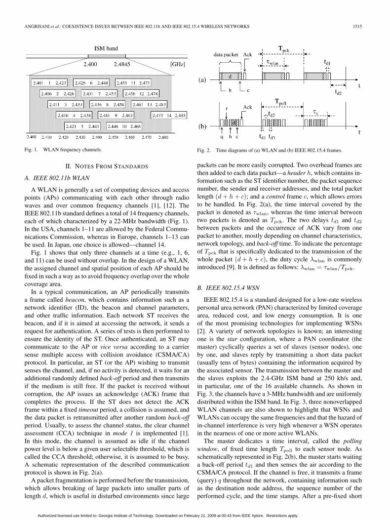
Fig. 1. WLAN frequency channels.
II. NOTES FROM STANDARDS
A. IEEE 802.11b WLAN
A WLAN is generally a set of computing devices and accesspoints (APs) communicating with each other through radiowaves and over common frequency channels [1], [12]. TheIEEE 802.11b standard defines a total of 14 frequency channels,each of which characterized by a 22-MHz bandwidth (Fig. 1).In the USA, channels 1–11 are allowed by the Federal Commu-nications Commission, whereas in Europe, channels 1–13 canbe used. In Japan, one choice is allowed—channel 14.
Fig. 1 shows that only three channels at a time (e.g., 1, 6,and 11) can be used without overlap. In the design of a WLAN,the assigned channel and spatial position of each AP should befixed in such a way as to avoid frequency overlap over the wholecoverage area.
In a typical communication, an AP periodically transmitsa frame called beacon, which contains information such as anetwork identifier (ID), the beacon and channel parameters,and other traffic information. Each network ST receives thebeacon, and if it is aimed at accessing the network, it sends arequest for authentication. A series of tests is then performed toensure the identity of the ST. Once authenticated, an ST maycommunicate to the AP or vice versa according to a carriersense multiple access with collision avoidance (CSMA/CA)protocol. In particular, an ST (or the AP) wishing to transmitsenses the channel, and, if no activity is detected, it waits for anadditional randomly defined back-off period and then transmitsif the medium is still free. If the packet is received withoutcorruption, the AP issues an acknowledge (ACK) frame thatcompletes the process. If the ST does not detect the ACKframe within a fixed timeout period, a collision is assumed, andthe data packet is retransmitted after another random back-offperiod. Usually, to assess the channel status, the clear channelassessment (CCA) technique in mode 1 is implemented [1].In this mode, the channel is assumed as idle if the channelpower level is below a given user selectable threshold, which iscalled the CCA threshold; otherwise, it is assumed to be busy.A schematic representation of the described communicationprotocol is shown in Fig. 2(a).
A packet fragmentation is performed before the transmission,which allows breaking of large packets into smaller parts oflength d, which is useful in disturbed environments since large
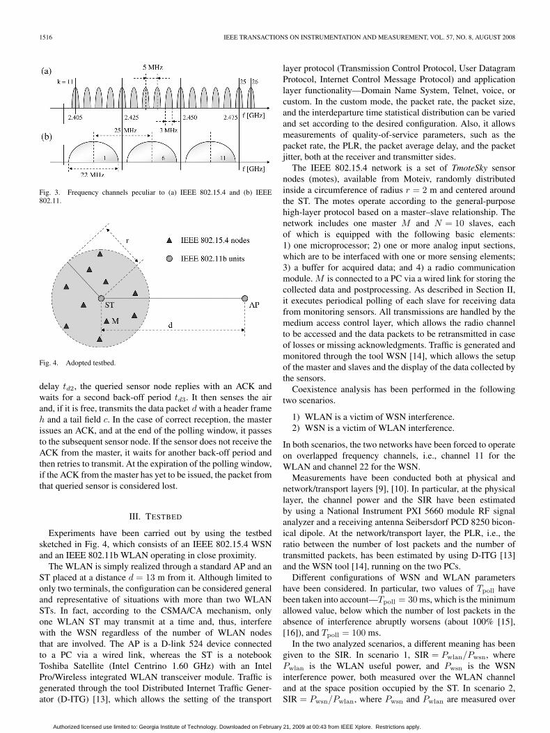
Fig. 2. Time diagrams of (a) WLAN and (b) IEEE 802.15.4 frames.
packets can be more easily corrupted. Two overhead frames arethen added to each data packet—a header h, which contains in-formation such as the ST identifier number, the packet sequencenumber, the sender and receiver addresses, and the total packetlength (d + h + c); and a control frame c, which allows errorsto be handled. In Fig. 2(a), the time interval covered by thepacket is denoted as τwlan, whereas the time interval betweentwo packets is denoted as Tpck. The two delays td1 and td2
between packets and the occurrence of ACK vary from onepacket to another, mostly depending on channel characteristics,network topology, and back-off time. To indicate the percentageof Tpck that is specifically dedicated to the transmission of thewhole packet (d + h + c), the duty cycle λwlan is commonlyintroduced [9]. It is defined as follows: λwlan = τwlan/Tpck.
B. IEEE 802.15.4 WSN
IEEE 802.15.4 is a standard designed for a low-rate wirelesspersonal area network (PAN) characterized by limited coveragearea, reduced cost, and low energy consumption. It is oneof the most promising technologies for implementing WSNs[2]. A variety of network topologies is known; an interestingone is the star configuration, where a PAN coordinator (themaster) cyclically queries a set of slaves (sensor nodes), oneby one, and slaves reply by transmitting a short data packet(usually tens of bytes) containing the information acquired bythe associated sensor. The transmission between the master andthe slaves exploits the 2.4-GHz ISM band at 250 kb/s and,in particular, one of the 16 available channels. As shown inFig. 3, the channels have a 3-MHz bandwidth and are uniformlydistributed within the ISM band. In Fig. 3, three nonoverlappedWLAN channels are also shown to highlight that WSNs andWLANs can occupy the same frequencies and that the hazard ofin-channel interference is very high whenever a WSN operatesin the nearness of one or more active WLANs.
The master dedicates a time interval, called the pollingwindow, of fixed time length Tpoll to each sensor node. Asschematically represented in Fig. 2(b), the master starts waitinga back-off period td1 and then senses the air according to theCSMA/CA protocol. If the channel is free, it transmits a frame(query) q throughout the network, containing information suchas the destination node address, the sequence number of theperformed cycle, and the time stamps. After a pre-fixed short
Authorized licensed use limited to: Georgia Institute of Technology. Downloaded on February 21, 2009 at 00:43 from IEEE Xplore. Restrictions apply.
1516 IEEE TRANSACTIONS ON INSTRUMENTATION AND MEASUREMENT, VOL. 57, NO. 8, AUGUST 2008
Fig. 3. Frequency channels peculiar to (a) IEEE 802.15.4 and (b) IEEE802.11.
Fig. 4. Adopted testbed.
delay td2, the queried sensor node replies with an ACK andwaits for a second back-off period td3. It then senses the airand, if it is free, transmits the data packet d with a header frameh and a tail field c. In the case of correct reception, the masterissues an ACK, and at the end of the polling window, it passesto the subsequent sensor node. If the sensor does not receive theACK from the master, it waits for another back-off period andthen retries to transmit. At the expiration of the polling window,if the ACK from the master has yet to be issued, the packet fromthat queried sensor is considered lost.
III. TESTBED
Experiments have been carried out by using the testbedsketched in Fig. 4, which consists of an IEEE 802.15.4 WSNand an IEEE 802.11b WLAN operating in close proximity.
The WLAN is simply realized through a standard AP and anST placed at a distance d = 13 m from it. Although limited toonly two terminals, the configuration can be considered generaland representative of situations with more than two WLANSTs. In fact, according to the CSMA/CA mechanism, onlyone WLAN ST may transmit at a time and, thus, interferewith the WSN regardless of the number of WLAN nodesthat are involved. The AP is a D-link 524 device connectedto a PC via a wired link, whereas the ST is a notebookToshiba Satellite (Intel Centrino 1.60 GHz) with an IntelPro/Wireless integrated WLAN transceiver module. Traffic isgenerated through the tool Distributed Internet Traffic Gener-ator (D-ITG) [13], which allows the setting of the transport
layer protocol (Transmission Control Protocol, User DatagramProtocol, Internet Control Message Protocol) and applicationlayer functionality—Domain Name System, Telnet, voice, orcustom. In the custom mode, the packet rate, the packet size,and the interdeparture time statistical distribution can be variedand set according to the desired configuration. Also, it allowsmeasurements of quality-of-service parameters, such as thepacket rate, the PLR, the packet average delay, and the packetjitter, both at the receiver and transmitter sides.
The IEEE 802.15.4 network is a set of TmoteSky sensornodes (motes), available from Moteiv, randomly distributedinside a circumference of radius r = 2 m and centered aroundthe ST. The motes operate according to the general-purposehigh-layer protocol based on a master–slave relationship. Thenetwork includes one master M and N = 10 slaves, eachof which is equipped with the following basic elements:1) one microprocessor; 2) one or more analog input sections,which are to be interfaced with one or more sensing elements;3) a buffer for acquired data; and 4) a radio communicationmodule. M is connected to a PC via a wired link for storing thecollected data and postprocessing. As described in Section II,it executes periodical polling of each slave for receiving datafrom monitoring sensors. All transmissions are handled by themedium access control layer, which allows the radio channelto be accessed and the data packets to be retransmitted in caseof losses or missing acknowledgments. Traffic is generated andmonitored through the tool WSN [14], which allows the setupof the master and slaves and the display of the data collected bythe sensors.
Coexistence analysis has been performed in the followingtwo scenarios.
1) WLAN is a victim of WSN interference.2) WSN is a victim of WLAN interference.
In both scenarios, the two networks have been forced to operateon overlapped frequency channels, i.e., channel 11 for theWLAN and channel 22 for the WSN.
Measurements have been conducted both at physical andnetwork/transport layers [9], [10]. In particular, at the physicallayer, the channel power and the SIR have been estimatedby using a National Instrument PXI 5660 module RF signalanalyzer and a receiving antenna Seibersdorf PCD 8250 bicon-ical dipole. At the network/transport layer, the PLR, i.e., theratio between the number of lost packets and the number oftransmitted packets, has been estimated by using D-ITG [13]and the WSN tool [14], running on the two PCs.
Different configurations of WSN and WLAN parametershave been considered. In particular, two values of Tpoll havebeen taken into account—Tpoll = 30 ms, which is the minimumallowed value, below which the number of lost packets in theabsence of interference abruptly worsens (about 100% [15],[16]), and Tpoll = 100 ms.
In the two analyzed scenarios, a different meaning has beengiven to the SIR. In scenario 1, SIR = Pwlan/Pwsn, wherePwlan is the WLAN useful power, and Pwsn is the WSNinterference power, both measured over the WLAN channeland at the space position occupied by the ST. In scenario 2,SIR = Pwsn/Pwlan, where Pwsn and Pwlan are measured over
Authorized licensed use limited to: Georgia Institute of Technology. Downloaded on February 21, 2009 at 00:43 from IEEE Xplore. Restrictions apply.

ANGRISANI et al.: COEXISTENCE ISSUES BETWEEN IEEE 802.11b AND IEEE 802.15.4 WIRELESS NETWORKS 1517
the WSN channel and by averaging the power readingsachieved at any sensor node position.
For the WSN and the WLAN, experiments have been exe-cuted in CCA mode 1, with a CCA threshold level Pth equalto −76 dBm (the default value). Moreover, measurements havebeen performed inside a nonshielded and nonanechoic room,hence, with the potential occurrence of external interferenceand collateral phenomena such as reflections from near metal-lic objects and structures. To also properly account for thisphenomenon, different positions of sensor nodes have beenconsidered.
IV. EXPERIMENTS IN THE CASE OF THE WLAN VICTIM
The WLAN behavior under the effect of WSN interferencehas been investigated both in the case of the AP transmitting tothe ST and vice versa.
A. Transmission From the AP to the ST
The conducted experiments have aimed to assess the be-havior of the WLAN under the effect of the WSN whenthe ST (located in the proximity to the WSN) receives datapackets from the AP (located far way from the WSN). Thisconfiguration has emulated the typical situation in which theWLAN transmitter (here, the AP) senses an interference powerlevel (from the WSN) below its CSMA/CA threshold, i.e., theWLAN channel is sensed free, thus enabling the transmission.
The first experiments have been conducted measuring thePLR of the WLAN, i.e., PLRwlan, in the case of SIR =−5.6 dB, for different values of the WLAN duty cycle λwlan
and the duration of the transmission window equal to 60 s.PLRwlan has been estimated as the ratio PLRwlan = 1 −Nrp/Ntp, where Nrp is the number of correctly receivedpackets, and Ntp is the number of packets delivered by theWLAN transmitter (here, the AP) in ideal conditions (i.e., inthe absence of interference). The quantity Ntp − Nrp can, inturn, be considered as the sum of two contributions, i.e., Ntp −Nrp = Nerp + Nntp, where Nerp is the number of packetserroneously gathered by the WLAN receiver (here, the ST) dueto signal collisions with WSN packets and/or channel errors,whereas Nntp is the number of packets not delivered by theWLAN transmitter (here, the AP) due to channel occupation.According to the above assumption about the AP location withrespect to the WSN position, Nntp is expected to be null in theanalyzed configuration.
The obtained results are summarized in Fig. 5, in which threediagrams are shown, where each referred to a specific size ofWLAN packets pswlan—600 B [Fig. 5(a)], 1112 B [Fig. 5(b)],and 1563 B [Fig. 5(c)], with a payload of 512, 1024, and1475 B, respectively. Different operative conditions of thetestbed have been analyzed—WSN off and WSN on withTpoll = 30 ms and Tpoll = 100 ms. The solid lines representthe PLRwlan estimates, whereas the dashed lines give the per-centage of packets that are not transmitted by the AP due tochannel occupation, i.e., Nntp/Ntp. Vertical bars also indicatethe standard deviation experimented under different positionsof the sensors.
From the analysis of the results, the following conclusionscan be drawn.
• In Fig. 5(a) and (b), as expected, the percentage of not-transmitted packetsNntp/Ntp is always null, irrespective ofthe chosen λwlan. This confirms that the AP always findsthe channel free, and it can transmit without interruption.
• In Fig. 5(c), Nntp/Ntp is not always null and increasesupon the increase of λwlan. This means that despite the factthat the channel is always assessed free, the AP encountersproblems when managing very long packet sizes.
• PLRwlan assumes quite the same values for pswlan =600 and 1112 B, whereas much higher losses are expe-rienced with pswlan = 1563 B. For instance, with λwlan =75%, WSN on, and Tpoll = 30 ms, the resulting PLRwlan
is 15%, 10%, and 100%, respectively.• In the absence of WSN interference, nonnegligible degra-
dation of WLAN performance is visible for any consideredλwlan. In particular, PLRwlan is constant and nearly equalto 5% up to a given threshold level of λwlan and is equalto 75%, 75%, and 53% for Fig. 5(a)–(c), respectively,whereas it increases even abruptly [see Fig. 5(c)] forhigher values.
• In the presence of WSN interference and Tpoll = 30 ms,WLAN performance degrades further. This is particularlytrue in the case of pswlan = 1563 B and λwlan ≤ 53%for which PLRwlan changes from nearly 5% (withoutinterference) up to 70% (for λwlan = 53%).
• In the presence of WSN interference, the threshold val-ues of λwlan, beyond which PLRwlan increases, reducefrom 75%, 75%, and 53% to 65%, 60%, and 30% forFig. 5(a)–(c), respectively.
• With a longer Tpoll of 100 ms, the effect of the WSN onthe WLAN is much weaker. In fact, with Tpoll = 100 ms,the estimated PLRwlan values are very close to the resultsachieved with WSN off.
• The dispersion of PLRwlan estimates around the corre-sponding mean values is almost always negligible. Theonly exception is given in Fig. 5(c), with WLAN on andTpoll = 30 ms.
Other experiments have been carried out with different levelsof the SIR from −13 up to −3 dB, two values of λwlan =56% and 75%, two values of Tpoll = 30 and 100 ms, andpswsn = 1112 B. The SIR has been changed by acting only onPwlan. The obtained results are summarized in Fig. 6, and thefollowing considerations arise.
• In the transition range −13 ≤ SIR ≤ −7 dB, PLRwlan
abruptly decreases from 100% to very low levels, i.e.,below 13%, upon the increase of the SIR.
• In the same range, the effect of Tpoll on PLRwlan is clearlyvisible; stretching Tpoll from 30 to 100 ms, PLRwlan
considerably decreases. For instance, with SIR = −11 dBand λwlan = 56%, PLRwlan is lowered from 34% to 10%by increasing Tpoll from 30 to 100 ms.
• In the upper range, i.e., SIR > −7 dB, the effect of Tpoll
and λwlan on PLRwlan is negligible. In fact, the same val-ues of PLRwlan, within 5%–12%, are achieved, regardlessof the chosen Tpoll and λwlan.
Authorized licensed use limited to: Georgia Institute of Technology. Downloaded on February 21, 2009 at 00:43 from IEEE Xplore. Restrictions apply.

1518 IEEE TRANSACTIONS ON INSTRUMENTATION AND MEASUREMENT, VOL. 57, NO. 8, AUGUST 2008
Fig. 5. PLR of the WLAN versus λwlan for different packet sizes. (a) 600 B. (b) 1112 B. (c) 1563 B.
• For levels of the SIR below −13 dB, WLAN packetsare completely lost, i.e., PLRwlan = 100%, regardless ofthe chosen value of λwlan and Tpoll. This is due to thereduced level of Pwlan that, for the considered SIR values,is comparable with or lower than the sensitivity levelof the ST, which is typically on the order of −84 dBm(in the case of data rate = 11 Mb/s).
• The experimental standard deviation is almost always neg-ligible, i.e., below 10%, with the exception of the highestPLRwlan.
B. Transmission From the ST to the AP
The conducted experiments have aimed at assessing thebehavior of the WLAN under the effect of the WSN inter-ference when the ST (located in the proximity to the WSN)is transmitting data packets to the AP (located far way fromthe WSN). This configuration has emulated the typical case inwhich the WLAN transmitter (here, the ST) senses a high levelof the WSN signal beyond its CCA threshold Pth. In this case,the presence of the WSN signal saturates the WLAN channel,
Authorized licensed use limited to: Georgia Institute of Technology. Downloaded on February 21, 2009 at 00:43 from IEEE Xplore. Restrictions apply.
ANGRISANI et al.: COEXISTENCE ISSUES BETWEEN IEEE 802.11b AND IEEE 802.15.4 WIRELESS NETWORKS 1519
Fig. 6. PLR of the WLAN versus the SIR for different λwlan.
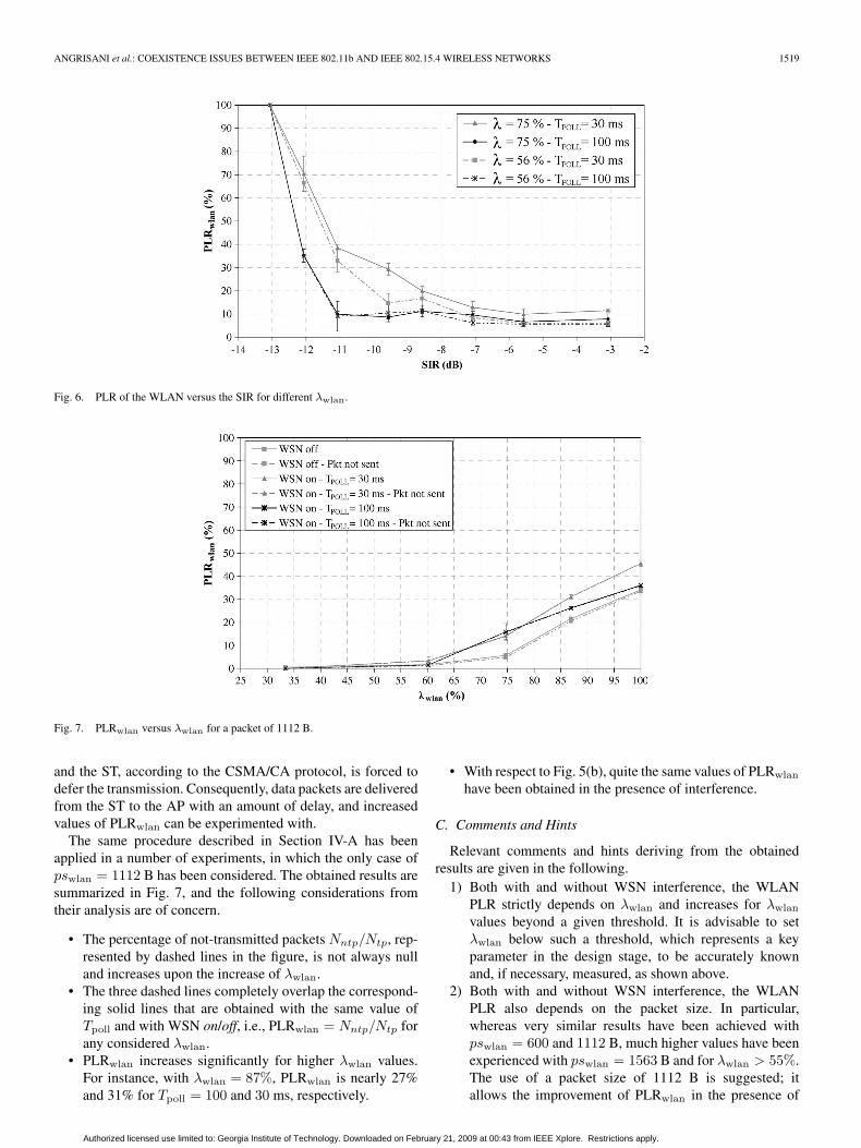
Fig. 7. PLRwlan versus λwlan for a packet of 1112 B.
and the ST, according to the CSMA/CA protocol, is forced todefer the transmission. Consequently, data packets are deliveredfrom the ST to the AP with an amount of delay, and increasedvalues of PLRwlan can be experimented with.
The same procedure described in Section IV-A has beenapplied in a number of experiments, in which the only case ofpswlan = 1112 B has been considered. The obtained results aresummarized in Fig. 7, and the following considerations fromtheir analysis are of concern.
• The percentage of not-transmitted packets Nntp/Ntp, rep-resented by dashed lines in the figure, is not always nulland increases upon the increase of λwlan.
• The three dashed lines completely overlap the correspond-ing solid lines that are obtained with the same value ofTpoll and with WSN on/off, i.e., PLRwlan = Nntp/Ntp forany considered λwlan.
• PLRwlan increases significantly for higher λwlan values.For instance, with λwlan = 87%, PLRwlan is nearly 27%and 31% for Tpoll = 100 and 30 ms, respectively.
• With respect to Fig. 5(b), quite the same values of PLRwlan
have been obtained in the presence of interference.
C. Comments and Hints
Relevant comments and hints deriving from the obtainedresults are given in the following.
1) Both with and without WSN interference, the WLANPLR strictly depends on λwlan and increases for λwlan
values beyond a given threshold. It is advisable to setλwlan below such a threshold, which represents a keyparameter in the design stage, to be accurately knownand, if necessary, measured, as shown above.
2) Both with and without WSN interference, the WLANPLR also depends on the packet size. In particular,whereas very similar results have been achieved withpswlan = 600 and 1112 B, much higher values have beenexperienced with pswlan = 1563 B and for λwlan > 55%.The use of a packet size of 1112 B is suggested; itallows the improvement of PLRwlan in the presence of
Authorized licensed use limited to: Georgia Institute of Technology. Downloaded on February 21, 2009 at 00:43 from IEEE Xplore. Restrictions apply.

1520 IEEE TRANSACTIONS ON INSTRUMENTATION AND MEASUREMENT, VOL. 57, NO. 8, AUGUST 2008
Fig. 8. PLRwsn versus λwlan for different WLAN packet sizes—600, 1112, and 1563 B—and Tpoll = 30 ms.
interference with respect to pswlan = 1563 B and higherthroughput with respect to pswlan = 600 B. This resultagrees with the values of the packet length obtained bysimulations in [6] for the same case of an IEEE 802.11bWLAN under the interference of an IEEE 802.15.4 WSN.
3) The WLAN PLR also strictly depends on the SIR. In par-ticular, PLRwlan may abruptly worsen for SIR values thatare below a given threshold, whereas for upper values,it assumes low levels and becomes quite independent ofWSN characteristics such as polling time. The SIR shouldbe always greater than this threshold, which can, in turn,be efficiently measured as described.
4) For the deployed testbed, the effects of WSN interference,in terms the WLAN PLR, are the same, regardless of thecommunication direction between the AP and the ST.
5) A different interference phenomenon arises depending onthe case of the AP transmitting to the ST or vice versa.In particular, in the case of the AP transmitting to theST, i.e., when the WLAN source is located far way fromthe WSN, interference comes out as collisions betweenWSN and WLAN data packets and/or channel errors.Conversely, in the case of the ST transmitting to the AP,i.e., when the WLAN source is closely located to theWSN, interference comes out as channel occupation dueto the presence of WSN emissions in the WLAN channeland the use, in the WLAN transmitter, of the CSMA/CAmechanism.
6) The increase in WSN polling time from 30 to 100 ms al-lows the mitigation of the interference effects of the WSNon the WLAN, particularly for λwlan and SIR valuescorresponding to when the estimated PLRwlan is greater.
7) In all the analyzed cases, very short standard deviationshave been experienced. External interference or collateralphenomena, such as reflections, have not introduced sig-nificant perturbations on conducted measurements.
V. EXPERIMENTS IN THE CASE OF THE WSN VICTIM
A second set of experiments has been carried out with theWSN victim and the WLAN interferer. Only the configuration
of the AP transmitting to the ST has been considered. It allows abetter investigation into the behavior of the WSN under WLANinterference, avoiding the effects of the WSN on the faraway-located AP. In fact, because of the low power level receivedby the AP from the WSN, i.e., below its CCA threshold, theAP always finds the channel free, and consequently, it can con-tinuously transmit, interfering the WSN without interruption.This is not true in the other case, i.e., the ST transmitting tothe AP, because of the near operation of WSN nodes, whichperiodically require accessing the same channel, hence with thehazard of disturbing the ST itself.
A. Results
Measurements have been conducted with three differentWLAN packet sizes—pswlan = 600, 1112, and 1563 B—at thesame level of sensor node output power Pmote = 0 dBmand Tpoll = 30 ms, which guarantee, in the absence of ra-dio interference, a null WSN PLR (denoted here as PLRwsn)[15]. The first experiments have been carried out with SIR =−3 dB and Pwlan greater than the CCA threshold of WSNmotes Pth.
In Fig. 8, the obtained results in terms of the WSN PLR,i.e., PLRwsn, upon varying the WLAN duty cycle λwlan aresummarized. The diagram clearly shows that, in the presenceof WLAN interference, PLRwsn abruptly degrades from 0%(with WLAN off) up to values that are always greater than50% for λwlan beyond 40%. Moreover, PLRwsn increases quitelinearly and quickly toward a saturation level comprised within75%–85%. In these cases, the probability for a WSN to find thechannel free, hence to begin transmission, is very low, and itworsens for shorter WLAN packet sizes. This phenomenon isclearly visible for values of λw up to 35% and is simply due tothe fact that, for a given λw, a shorter time interval between twoconsecutive WLAN packets (Tpck − τw) is available for WSNtransmission.
To avoid such critical degradation of WSN performance inthe presence of WLAN interference, an efficient solution hasconsisted of increasing Tpoll, for instance, from 30 to 100 ms.Some tests have been performed with the suggested solution,
Authorized licensed use limited to: Georgia Institute of Technology. Downloaded on February 21, 2009 at 00:43 from IEEE Xplore. Restrictions apply.
ANGRISANI et al.: COEXISTENCE ISSUES BETWEEN IEEE 802.11b AND IEEE 802.15.4 WIRELESS NETWORKS 1521
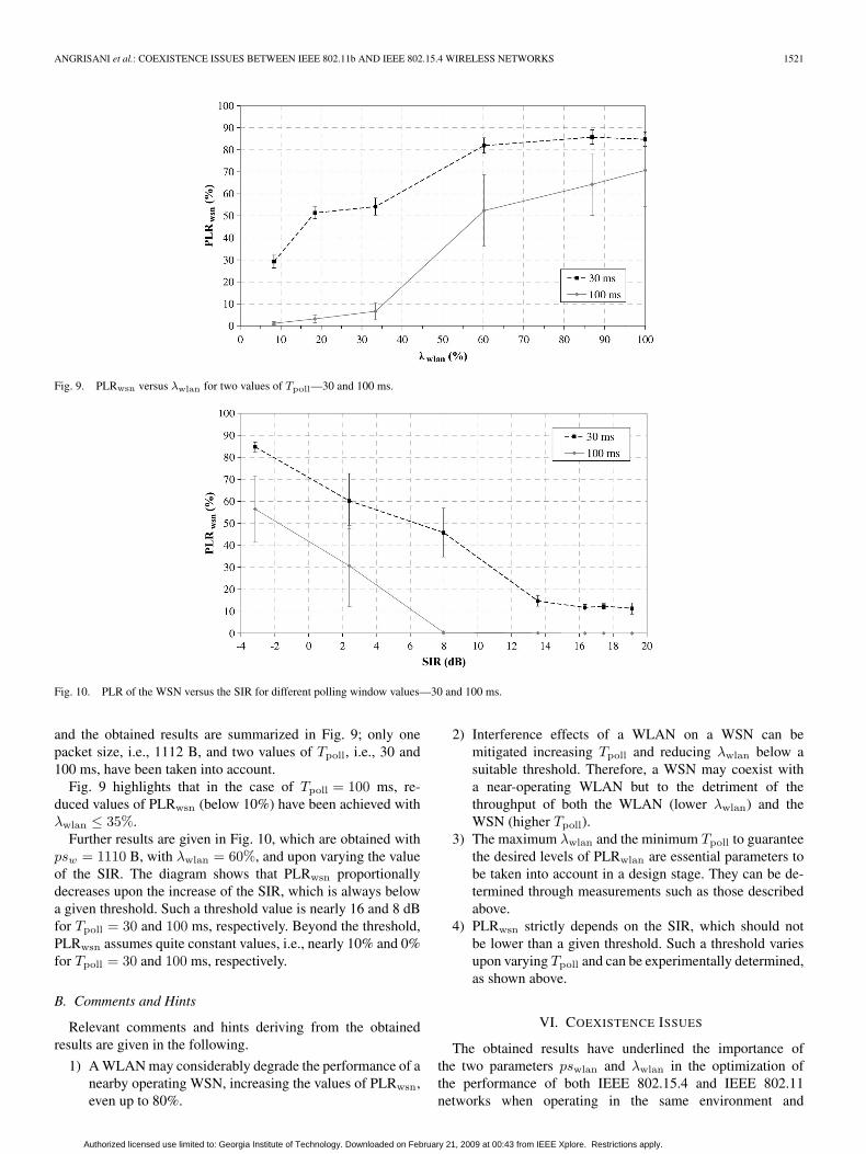
Fig. 9. PLRwsn versus λwlan for two values of Tpoll—30 and 100 ms.
Fig. 10. PLR of the WSN versus the SIR for different polling window values—30 and 100 ms.
and the obtained results are summarized in Fig. 9; only onepacket size, i.e., 1112 B, and two values of Tpoll, i.e., 30 and100 ms, have been taken into account.
Fig. 9 highlights that in the case of Tpoll = 100 ms, re-duced values of PLRwsn (below 10%) have been achieved withλwlan ≤ 35%.
Further results are given in Fig. 10, which are obtained withpsw = 1110 B, with λwlan = 60%, and upon varying the valueof the SIR. The diagram shows that PLRwsn proportionallydecreases upon the increase of the SIR, which is always belowa given threshold. Such a threshold value is nearly 16 and 8 dBfor Tpoll = 30 and 100 ms, respectively. Beyond the threshold,PLRwsn assumes quite constant values, i.e., nearly 10% and 0%for Tpoll = 30 and 100 ms, respectively.
B. Comments and Hints
Relevant comments and hints deriving from the obtainedresults are given in the following.
1) A WLAN may considerably degrade the performance of anearby operating WSN, increasing the values of PLRwsn,even up to 80%.
2) Interference effects of a WLAN on a WSN can bemitigated increasing Tpoll and reducing λwlan below asuitable threshold. Therefore, a WSN may coexist witha near-operating WLAN but to the detriment of thethroughput of both the WLAN (lower λwlan) and theWSN (higher Tpoll).
3) The maximum λwlan and the minimum Tpoll to guaranteethe desired levels of PLRwlan are essential parameters tobe taken into account in a design stage. They can be de-termined through measurements such as those describedabove.
4) PLRwsn strictly depends on the SIR, which should notbe lower than a given threshold. Such a threshold variesupon varying Tpoll and can be experimentally determined,as shown above.
VI. COEXISTENCE ISSUES
The obtained results have underlined the importance ofthe two parameters pswlan and λwlan in the optimization ofthe performance of both IEEE 802.15.4 and IEEE 802.11networks when operating in the same environment and
Authorized licensed use limited to: Georgia Institute of Technology. Downloaded on February 21, 2009 at 00:43 from IEEE Xplore. Restrictions apply.

1522 IEEE TRANSACTIONS ON INSTRUMENTATION AND MEASUREMENT, VOL. 57, NO. 8, AUGUST 2008
Fig. 11. (Dashed lines) PLRwsn and (solid lines) PLRwlan for a different setup of a WLAN.
sharing the same frequencies. Their choice can be simplifiedand optimized by using comprehensive diagrams such as thatin Fig. 11, which is obtained by gathering the results ofFigs. 5 and 8.
The diagram shows two sets of curves—the dashed ones givethe values of pswlan and λwlan that guarantee a given levelof PLRwsn (indicated through vertically oriented numbers),whereas the solid ones represent the values of pswlan and λwlan
that guarantee a given level of PLRwlan (indicated throughhorizontal-oriented numbers). The two sets of curves refer toTpoll = 30 ms.
The diagram fixes the couple of pswlan and λwlan valuesallowing the increase in the WLAN throughput (which can bepursed increasing pswlan and/or λwlan) and the minimization ofPLRwsn and PLRwlan. For instance, with a maximum PLRwsn
of 24.4% and a maximum PLRwlan of 9.0%, the diagramshows that the two parameters pswlan and λwlan must be inthe region on the left of the curve with PLRwsn = 24.4%,which means that a very low λwlan must be chosen, andconsequently, low WLAN throughput is obtained. Instead, inthe case of a maximum PLRwsn of 79.0% and a maximumPLRwlan of 9.0%, a much greater region of pswlan and λwlan
values is available. In this case, it can be noted that to in-crease the WLAN throughput, a solution is to reduce theWLAN packet size, which allows greater values of λwlan
to be set.In general, the graph confirms that the predominant effect
of interference is from the WLAN to the WSN. In fact, withpswlan ≤ 1112 B, all the PLRwsn curves are on the left withrespect to the corresponding ones (having the same PLR level)of PLRwlan. Therefore, in this case, for any chosen λwlan,PLRwlan � PLRwsn.
VII. CONCLUSION
The experimental analysis has confirmed that the WLANand the IEEE 802.15.4 WSNs may coexist when operatingin close proximity but to the detriment of some performanceparameters such as the PLR and the throughput. In the case
of the WLAN victim, the WLAN duty cycle must always beset lower than a given threshold value, which depends on theWLAN packet size, decreases in the case of WSN interference,and can be determined as described above. Moreover, in thepresence of WSN interference, the WLAN PLR does not signif-icantly depend on the number and the position of WSN nodesinside a fixed circumference that is centered around the WLANreceiver.
In the opposite case, i.e., the WSN victim, much more visibleloss of WSN packets arising when the WLAN transmits hasbeen observed. In particular, at the beginning of the WLAN op-eration, the PLR abruptly increases from 0% to values beyond70%. In this case, to enhance the WSN reliability, a solutionmay be either to increase the time duration of the pollingwindow in such a way as to have more possibilities to correctlyretransmit or to reduce the WLAN duty cycle. Unfortunately,this solution causes lower throughput of the WSN, if a longerpolling window is set, or of the WLAN, if the duty cycle isreduced.
REFERENCES
[1] Part 11: Wireless LANMedium Access Control (MAC) and Physical Layer(PHY) Specifications, IEEE Std. 802.11b 1999/Cor 1-2001, 2001.
[2] Part 15.4: Wireless Medium Access Control (MAC) and Physical Layer(PHY) Specifications for Low-Rate Wireless Personal Area Networks (LR-WPANs), IEEE Std. 802.15.4, Oct. 2003.
[3] I. Howitt, “WLAN and WPAN coexistence in UL band,” IEEE Trans. Veh.Technol., vol. 50, no. 4, pp. 1114–1124, Jul. 2001.
[4] I. Howitt and J. Gutierrez, “IEEE 802.15.4 low rate-wireless personalarea network coexistence issues,” in Proc. Wireless Commun. Netw. Conf.,Mar. 2003, vol. 3, pp. 1481–1486.
[5] K. J. Myoung, S. Y. Shin, H. S. Park, and W. H. Kwon, “IEEE 802.11bperformance analysis in the presence of IEEE 802.15.4 interference,”IEICE Trans. Commun., vol. E90-B, no. 1, pp. 176–179, Jan. 2007.
[6] D. G. Yoon, S. Y. Shin, W. H. Kwon, and H. S. Park, “Packet error rateanalysis of IEEE 802.11b under IEEE 802.15.4 interference,” in Proc.Veh. Technol. Conf., May 7–10, 2006, vol. 3, pp. 1186–1190.
[7] S. Y. Shin, H. S. Park, S. C. Choi, and W. H. Kwon, “Packet error rateanalysis of IEEE 802.15.4 under IEEE 802.11b interference,” in Proc.WWIC, 2005, pp. 279–288.
[8] A. Sikora and V. F. Groza, “Coexistence of IEEE802.15.4 with othersystems in the 2.4 GHz-ISM-band,” in Proc. IMTC, Ottawa, ON,May 16–19, 2005, pp. 1786–1791.
Authorized licensed use limited to: Georgia Institute of Technology. Downloaded on February 21, 2009 at 00:43 from IEEE Xplore. Restrictions apply.
ANGRISANI et al.: COEXISTENCE ISSUES BETWEEN IEEE 802.11b AND IEEE 802.15.4 WIRELESS NETWORKS 1523
[9] N. Golmie, R. E. Van Dyck, A. Soltanian, A. Tonnere, and O. Rebala,“Interference evaluation of bluetooth and IEEE802.11b systems,” Wirel.Netw., vol. 9, pp. 201–211, 2003.
[10] L. Angrisani and M. Vadursi, “Cross-layer measurements for a compre-hensive characterization of wireless networks in the presence of inter-ference,” IEEE Trans. Instrum. Meas., vol. 56, no. 4, pp. 1148–1156,Aug. 2007.
[11] L. Angrisani, M. Bertocco, D. Fortin, and A. Sona, “Assessing coexistenceproblems of IEEE 802.11b and IEEE 802.15.4 wireless sensor networksthrough cross-layer measurements,” in Proc. IMTC, Warsaw, Poland,May 1–3, 2007.
[12] Part 11: Wireless LANMedium Access Control (MAC) and Physical Layer(PHY) Specifications, ANSI/IEEE Std. 802.11, 1999.
[13] [Online]. Available: http://grid.unina.it/software/ITG[14] [Online]. Available: http://www.dei.unipd.it/ricerca/gmee[15] M. Bertocco, G. Gamba, A. Sona, and S. Vitturi, “Performance mea-
surements of CSMA/CA-based wireless sensor networks for industrialapplications,” in Proc. IMTC, Warsaw, Poland, May 1–3, 2007.
[16] S. Vitturi, I. Carreras, D. Miorandi, L. Schenato, and A. Sona, “Exper-imental evaluation of an industrial application layer protocol over wire-less systems,” IEEE Trans. Ind. Informat., vol. 3, no. 4, pp. 275–288,Nov. 2007.
Leopoldo Angrisani (M’08) was born in NoceraSuperiore, SA, Italy, on April 16, 1969. He receivedthe M.S. degree (cum laude) in electronic engineer-ing from the University of Salerno, Salerno, Italy, in1993 and the Ph.D. degree in electrical engineeringfrom the University of Napoli Federico II, Napoli,Italy, in 1997.
Since 2002, he has been an Associate Professorwith the Dipartimento di Informatica e Sistemistica,Università degli Studi di Napoli Federico II. Hisresearch activity is focused on typical topics of
electrical and electronic measurements and, in particular, on the definitionand the implementation of new digital signal processing methods for theperformance assessment of telecommunication systems and apparatuses; thedefinition and the implementation of new methods for communication networktest and measurement; the definition and the implementation of new digitalsignal processing methods for the detection, measurement, and classificationof nonstationary signals; design, realization, and metrological characterizationof automatic measurement instruments based on digital signal processors; andthe definition and the implementation of alternative methods for uncertaintyevaluation in indirect measurements.
Matteo Bertocco (M’92) was born in Padova, Italy,in 1962. He received the Laurea degree and thePh.D. degree from the University of Padova, Padova,both in electronics engineering in 1987 and 1991,respectively.
In 1994, he joined the Department of Electronicsand Informatics, University of Padova, as a Re-searcher, where he became an Associate Professorwith the Electronic Instrumentation and Measure-ment in 1998 and, since 2005, has been a FullProfessor. He has taken part in a number of national
and international research projects, including the European Union fourth andfifth framework programs. He is the author of over 140 scientific papersand textbooks for academic courses. His research interests include digitalsignal processing, estimation, virtual systems, automated instrumentation, andelectromagnetic compatibility.
Daniele Fortin (S’07) was born in Padova, Italy,in 1977. He received the Laurea degree in telecom-munications engineering and the Ph.D. degree ininformation engineering, with a course in bioelectro-magnetism and electromagnetic compatibility, fromthe University of Padova in 2004 and 2008, respec-tively.
He is currently with the University of Padova. Hisresearch interests include wireless communications(DVB, WLANs, and WSNs), which are focusedon measurement methodologies for the performance
assessment of digital communication systems.
Alessandro Sona (M’05) received the Laurea de-gree (summa cum laude) in electronics engineeringfrom the University of Padova, Padova, Italy, in1999 and the Ph.D. degree in electronic instrumen-tation from the University of Brescia, Brescia, Italy,in 2002.
Since then, he has been with the Department of In-formation Engineering, University of Padova, wherehe is currently an Assistant Professor of instrumen-tation and measurement. His main interests are in thefield of measurement uncertainty, electromagnetic
compatibility, and wireless communication systems and networks. In particular,his research is focused on new measurement techniques and tools for theanalysis of electromagnetic compatibility phenomena and on performanceevaluation of digital communication systems in the presence of interference.He is currently responsible for several internal projects on electromagneticcompatibility, digital communications, and sensor networks.
Authorized licensed use limited to: Georgia Institute of Technology. Downloaded on February 21, 2009 at 00:43 from IEEE Xplore. Restrictions apply.