experimental study of external diaphragm joint · pdf fileexperimental study of external...
TRANSCRIPT
Advanced Steel Construction Vol. 6, No. 1, pp. 578-588 (2010) 578
EXPERIMENTAL STUDY OF EXTERNAL DIAPHRAGM JOINT CONNECTING CHS COLUMN AND H-SHAPED BEAM
W.Q. Li1,*, Y.Y. Chen1, 2, W. Wang1, 2, Y.J. Xu3 and X.D. Lv3
1 Department of Structural Engineering, Tongji University, Shanghai 200092, China
2State Key Laboratory for Disaster Reduction in Civil Engineering, Shanghai 200092, China 3China Northwest Building Design Research Institute, Xi’an 710003, China
*(Corresponding author: E-mail: [email protected])
Received: 25 February 2008; Revised: 13 October 2008; Accepted: 20 November 2008
ABSTRACT: This paper focuses on external diaphragm joint connecting CHS column and H-shaped beam. Quasi-static tests on three cruciform specimens and finite element analysis using PATRAN/MARC were carried out. The width of diaphragm plate is taken as the test parameter. Four types of failure mode were observed: local buckling of CHS column, noticeable shear deformation at joint zone, doglegged deformation of CHS column, as well as crack at the heat affected zone of CHS column. The specimens exhibited full hysteresis loops, but different initial stiffness and ultimate capacity. Analytical results match the test well and are used to comprehend the force transfer mechanisms between beam flange and diaphragm plate. Keywords: External Diaphragm Joint, CHS Column, H-shaped Beam, Quasi-static test, finite element analysis
1. INTRODUCTION For steel building frames, circular hollow section tube and H-steel are suitable for column and beam members respectively. Basically, there are three types of joints connecting CHS column and H-shaped beams commonly used in moment-resisting steel frames: through diaphragm joint, inner diaphragm joint and external diaphragm joint. Among them, external diaphragm joint is most convenient for construction. When forming the external diaphragm joint, the diaphragm plates are welded around the periphery of the column to avoid the cut of the tube in joint zone. It should be potential benefit considering a water-cooling system in steel column to be used (Sakumoto [1]) in order to prevent from fire heating in high-rise buildings. Though studies have been carried out by previous research, there are still some unclear points remained for the behavior of the joint. Rink et al. [2] investigated the static strength of external diaphragm joint by numerical method. They found that increasing the width of diaphragm plate would not increase the ultimate capacity as much as that predicted by the AIJ formula. Kamba and Kanatani [3] explained the AIJ formula in detail and concluded that difference of failure mechanism and limiting width-to-thickness ratio of diaphragm plate resulted in the discrepancy between results of Rink et al. and AIJ formula. On the other hand, in the engineering practices in China, the width of the external diaphragm not less than 70% of the width of the beam flange is required. It is on the assumption that the force from the beam flange is transferred entirely through the external diaphragm. Wang et al. [4] performed finite element analysis of external diaphragm type joint under vertical load and pointed out the Chinese provision may be conservative or dangerous under different ratios of axially compressive load to axially yielding force of the column section. In this paper, the authors report experimental research about the beam-column joint in which the width of external diaphragm plate is taken as a parameter and the specimen is under combined force condition including compressive load on column and cyclic shear-moment action on ends of members. Additionally, finite element analysis using PATRAN/MARC was conducted, and the force transfer mechanism between beam flange and diaphragm plate was discussed.
The Hong Kong Institute of Steel Construction www.hkisc.org
579 W.Q. Li, Y.Y. Chen, W. Wang, Y.J. Xu and X.D. Lv
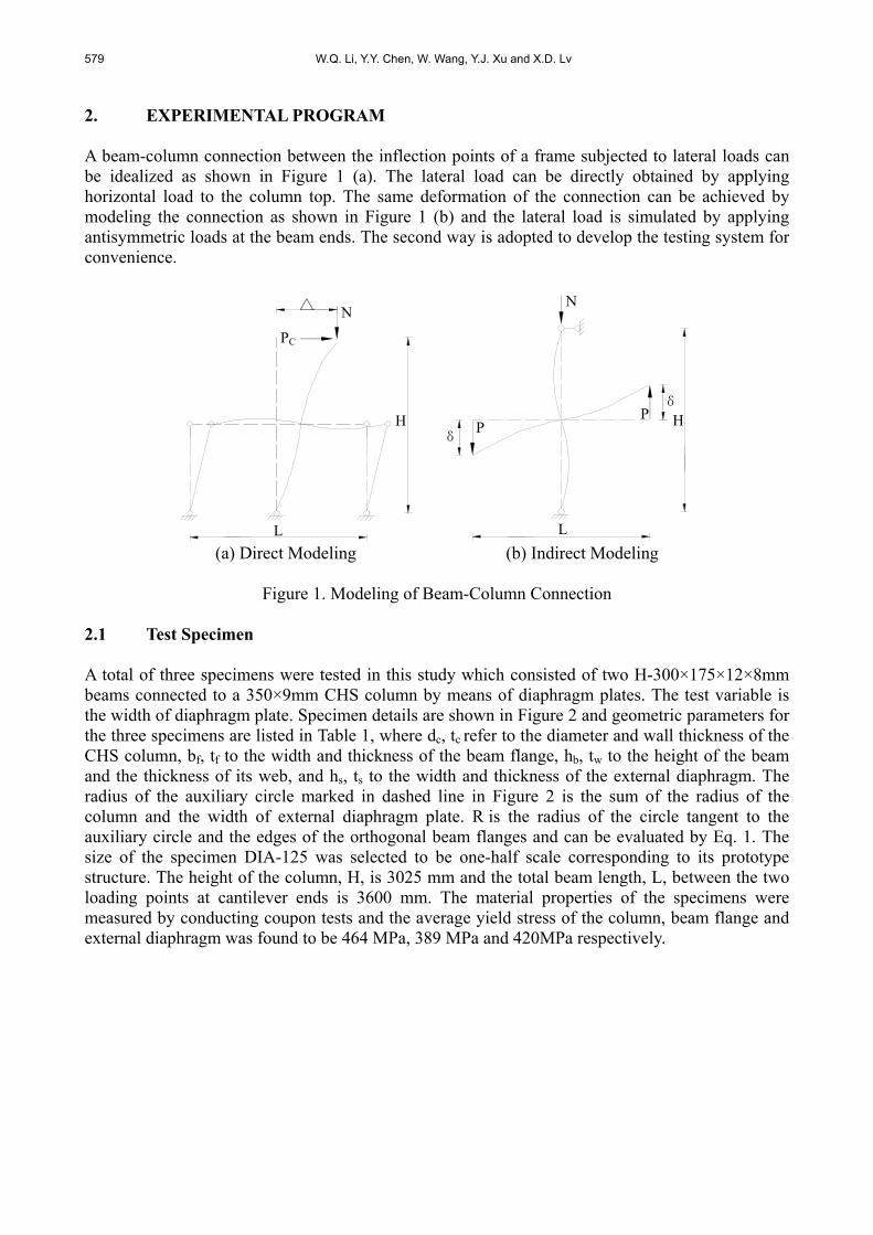
2. EXPERIMENTAL PROGRAM A beam-column connection between the inflection points of a frame subjected to lateral loads can be idealized as shown in Figure 1 (a). The lateral load can be directly obtained by applying horizontal load to the column top. The same deformation of the connection can be achieved by modeling the connection as shown in Figure 1 (b) and the lateral load is simulated by applying antisymmetric loads at the beam ends. The second way is adopted to develop the testing system for convenience.
L
H
PC
N △ △
L
H
N
PP
δ
δ
(a) Direct Modeling (b) Indirect Modeling
Figure 1. Modeling of Beam-Column Connection
2.1 Test Specimen A total of three specimens were tested in this study which consisted of two H-300×175×12×8mm beams connected to a 350×9mm CHS column by means of diaphragm plates. The test variable is the width of diaphragm plate. Specimen details are shown in Figure 2 and geometric parameters for the three specimens are listed in Table 1, where dc, tc refer to the diameter and wall thickness of the CHS column, bf, tf to the width and thickness of the beam flange, hb, tw to the height of the beam and the thickness of its web, and hs, ts to the width and thickness of the external diaphragm. The radius of the auxiliary circle marked in dashed line in Figure 2 is the sum of the radius of the column and the width of external diaphragm plate. R is the radius of the circle tangent to the auxiliary circle and the edges of the orthogonal beam flanges and can be evaluated by Eq. 1. The size of the specimen DIA-125 was selected to be one-half scale corresponding to its prototype structure. The height of the column, H, is 3025 mm and the total beam length, L, between the two loading points at cantilever ends is 3600 mm. The material properties of the specimens were measured by conducting coupon tests and the average yield stress of the column, beam flange and external diaphragm was found to be 464 MPa, 389 MPa and 420MPa respectively.

Experimental Study of External Diaphragm Joint Connecting CHS Column and H-Shaped Beam 580
(a) Elevation View (b) Plan View
Figure 2. Specimen Details
Table 1. Geometric Parameters of Test Specimens
Specimen dc
(mm) tc
(mm) bf
(mm)tf
(mm) hb
(mm)tw
(mm)hs
(mm) ts
(mm) hs / bf
DIA-125* 125 14 0.71 DIA-75 75 14 0.43 DIA-45
350 9 175 12 300 8 45 14 0.26
*The beam flange is locally widened to 275 mm at the end connected to the external diaphragm.
fs
co
2
2
222.5ctg bh
dR (1)
2.2 Test Setup The specimens were tested in State Key Laboratory of Disaster Prevention in Civil Engineering at Tongji University. The test setup was designed to implement the load and boundary conditions shown in Figure 1 (b). Figure 3 shows a schematic of the test setup. Spherical bearings were placed at the two ends of the beam as well as the top and the bottom of the column to achieve the expected restraint as perfect pin-boundary conditions. The spherical bearing at the top of the column was attached to the steel reaction frame with one tubular brace, and the other at the bottom of the column was fixed on the foundation, which was attached to the steel reaction frame with a foundation beam. The spherical bearings at the two ends of the beam were connected with the two-way hydraulic jacks by high-strength bolts. A load cell was mounted between the two-way jack and the spherical bearing at the east beam end to monitor the actual applied load. These jacks were fixed on the foundation beam and the steel reaction frame respectively. A 3200 kN one-way hydraulic jack was placed at the top of the column to apply compressive load. Lateral reaction trusses assembled from angle irons were provided to hold back out-of-plane movement of the beams. The test setup had a displacement capacity of ±250 mm and a load capacity of ±300 kN. The specimens were instrumented to monitor the response during the loading process in order to comprehend the specimen behavior, as shown in Figure 4. Strain gauges were glued at the external diaphragm, the panel zone, the beam and the column near the joint zone to investigate local response. Displacement transducers were placed at the west and east end of the beam, the top and the bottom of the column. Corresponding to those positions, displacement measurements are denoted by δ1, δ2, δ3 and δ4. The relative displacement of the west and east beam end, δ, was calculated from the total displacement by subtracting the rigid body motion of the specimen, as

581 W.Q. Li, Y.Y. Chen, W. Wang, Y.J. Xu and X.D. Lv
shown in Eq. 2 and Eq. 3. Readings from the displacement transducers at the panel zone were used to calculate the panel shear deformation γ. The vertical load, P, applied to the ends of cantilever beams was measured by the load cell. The global rotation of the connection, θ, and the moment of the connection, M, can be computed by Eq. 4 and Eq. 5, respectively.
(Lateral reaction trusses are not shown for clarity)
Figure 3. Schematic of Test Setup
Figure 4. Specimen Instrumentation
HL 431 5.0 (2)
HL 432 5.0 (3)
c5.05.0 dL (4)
c5.05.0 dLPM (5)
Jack_2
Jack_1
Load cell
East
Spherical Bearing_2
Steel reaction frame
Tubular brace(φ203x18)
Spherical Bearing_1
Test specimen
West
Spherical Bearing_2
Jack_1
Foundation beam (I400x300x20x20)
Spherical Bearing_1
Foundation

Experimental Study of External Diaphragm Joint Connecting CHS Column and H-Shaped Beam 582
2.3 Test Procedure Each test specimen was subjected to a constant axial load on column and cyclic loads on beams. Axially compressive load was first applied to the top of the column by the compressive hydraulic jack until it reached the given value 0.27Ny, where Ny is the axially yielding force of the member section, and held constant during the entire loading process. Antisymmetric cyclic loads were then synchronously applied to cantilever ends of beams by the two-way hydraulic jacks. The specimens were tested under force control at the beginning cycles. After yielding, the test was converted to displacement control, following a loading history composed of stepwise increasing deformation cycles and cycling continued until the ultimate capacity of the specimen was reached or the apparatus limitation was exceeded. In fact, displacement control can not be automatically realized by the two-way jacks and must be mated with manually monitoring the readings from the displacement transducers arranged at beam ends. 3. EXPERIMENTAL RESULTS 3.1 Hysteretic Behavior The plots of the connection moment normalized by the complete plastic moment capacity of beam versus the global rotation of the connection are shown in Figure 5 to 7. The curves indicate good capacity of energy dissipation for the three specimens by the full and stable hysteretic loops. The maximum moment capacity of specimen DIA-125 and DIA-75 are slightly greater than or almost same as the full plastic moment of its beams, while that of specimen DIA-45 is around 10% lower than the beam full plastic moment. The initial stiffness and maximum moment capacity of the specimens are shown in Table 2. The initial stiffness, Ki, is obtained by linear regression analysis of the M-θ history from the first elastic cycle. The maximum moment capacity, Mmax, is calculated by multiplying the maximum force recorded by the load cell by the distance from the center of the two-way jack to the interface of the column. The maximum moment capacity of specimen DIA-125 is 8% higher than that of specimen DIA-75 and 25% higher than that of specimen DIA-45. The initial stiffness of specimen DIA-125 is 16% higher than that of specimen DIA-75 and 22% higher than that of specimen DIA-45. The fact indicates that the initial stiffness and maximum moment capacity of the specimen are closely related to the width of diaphragm plate. 3.2 Failure Mode Specimens after tests are shown in Figure 8 to 10. Local buckling occurred at the column near the external diaphragm for all the three specimens when the connection moment reached 293kN-m, 268kN-m and 258kN-m, respectively. Typical strain development in the corresponding zone is shown in Figure 11. For specimen DIA-125, the panel zone underwent noticeable shear deformation and crack was observed in the heat affected zone of the column near the external diaphragm. For specimen DIA-75, the doglegged deformation of CHS column appeared in the large deformation range. For specimen DIA-45, noticeable shear deformation of the panel zone was also observed. Local buckling or fracture of the diaphragm plate did not appear. The strain gauge data show that the specimens differed in yielding sequence of different locations. For specimen DIA-125, the diaphragm yielded after the panel zone and the column. For specimen

583 W.Q. Li, Y.Y. Chen, W. Wang, Y.J. Xu and X.D. Lv
DIA-75, the diaphragm yielded following the yielding of panel zone while ahead of the column. For specimen DIA-45, the diaphragm yielded before the panel zone and the column.
-1.2-1.0-0.8-0.6-0.4-0.20.00.20.40.60.81.01.2
-12 -9 -6 -3 0 3 6 9 12
θ (×10-2 rad)
M/M
p
TEST
FEA
-1.2-1.0-0.8-0.6-0.4-0.20.00.20.40.60.81.01.2
-12 -9 -6 -3 0 3 6 9 12
θ (×10-2 rad)
M/M
p
TEST
FEA
(a) Beam West End (b) Beam East End
Figure 5. Moment-Rotation Hysteretic Loops for Specimen DIA-125
-1.2-1.0-0.8-0.6-0.4-0.20.00.20.40.60.81.01.2
-12 -9 -6 -3 0 3 6 9 12
θ (×10-2 rad)
M/M
p
TEST
FEA
-1.2-1.0-0.8-0.6-0.4-0.20.00.20.40.60.81.01.2
-12 -9 -6 -3 0 3 6 9 12
θ (×10-2 rad)
M/M
p
TEST
FEA
(a) Beam West End (b) Beam East End
Figure 6. Moment-Rotation Hysteretic Loops for Specimen DIA-75
-1.2-1.0-0.8-0.6-0.4-0.20.00.20.40.60.81.01.2
-12 -9 -6 -3 0 3 6 9 12
θ (×10-2 rad)
M/M
p
TEST
FEA
-1.2-1.0-0.8-0.6-0.4-0.20.00.20.40.60.81.01.2
-12 -9 -6 -3 0 3 6 9 12
θ (×10-2 rad)
M/M
p
TEST
FEA
(a) Beam West End (b) Beam East End
Figure 7. Moment-Rotation Hysteretic Loops for Specimen DIA-45

Experimental Study of External Diaphragm Joint Connecting CHS Column and H-Shaped Beam 584
Table 2. Test Results
SpecimenKi
(kN-m/rad)Mmax
(kN-m) DIA-125 16968 322 DIA-75 14574 297 DIA-45 13887 258
(a) Local Buckling (b) Crack (c) Excessive Shear Deformation
Figure 8. Failure Mode of Specimen DIA-125
(a) Local Buckling (b) Doglegged Deformation
Figure 9. Failure Mode of Specimen DIA-175
(a) Local Buckling (b) Excessive Shear Deformation
Figure 10. Failure Mode of Specimen DIA-45

585 W.Q. Li, Y.Y. Chen, W. Wang, Y.J. Xu and X.D. Lv
-400
-300
-200
-100
0
100
200
300
400
-30000 -20000 -10000 0 10000
ε (×10-6)
M(k
N-m
)
-400
-300
-200
-100
0
100
200
300
400
-30000 -20000 -10000 0 10000
ε (×10-6)
M(k
N-m
)
(a) DIA-125 (b) DIA-75
-400
-300
-200
-100
0
100
200
300
400
-30000 -20000 -10000 0 10000
ε (×10-6)
M(k
N-m
)
(c) DIA-45
Figure 11. Typical Strain Development in Local Buckling Zone
3.3 Comparison with AIJ Formula The yield shear strength of the joint panel and the connection resistance can be calculated according to Recommendation of Architectural Institute of Japan [5,6], and the results are listed in Table 3. In the table, Msy, Mcy, My and Mu are the calculated moment capacity of connection corresponding to the yield shear strength of the panel zone, the yield moment strength of the column, the yield strength of the connection and the ultimate strength of the connection respectively. The yielding sequences of different parts of the three specimens predicted by design formulas are in accordance with those observed in the tests as mentioned above. However, the maximum strength of the specimen obtained from the tests does not correspond well with the ultimate strength of the connection predicted by the AIJ formula.
Table 3. Calculated Strength of Different Parts
Specimen Msy
(kN-m) Mcy
(kN-m)My
(kN-m)Mu
(kN-m) DIA-125 294 392 DIA-75 233 310 DIA-45
200 260 172 229
*Geometric parameters of the connections are slightly beyond the valid range suggested by AIJ

Experimental Study of External Diaphragm Joint Connecting CHS Column and H-Shaped Beam 586
4. FINITE ELEMENT ANALYSIS 4.1 Finite Element Modeling Monotonic finite element analysis is performed to comprehend the force transfer mechanism between beam flange and external diaphragm. PATRAN and MARC [7] are used for mesh generation and analysis, respectively. Four-node quadrilateral shell elements with reduced integration (MRAC element type 140) are used to model the specimens. The mesh at the joint panel and external plates is densified. A representative finite element model is shown in Figure 12. Material properties are input according to the data from coupon tests. Classical metal plasticity theory based on Von Mises yield criterion, isotropic hardening and associated flow rule is assumed. Actual load and boundary conditions are specified. Geometric nonlinearities are accounted for through a small-strain, large-displacement formulation.
(a) Specimen (b) Joint (c) External Diaphragm
Figure 12. Typical Finite Element Mesh
4.2 Verification The numerical moment-rotation curves are shown in Figure 5 to 7. One of the typical deformed shapes predicted by numerical analysis is exhibited in Figure 13. Although no direct comparison was possible, good correlation between the numerical and the experimental work was obtained.
Figure 13. Deformed Shape of FE Model (DIA-125)
4.3 Discussion of Force Transfer Mechanism As mentioned above, in the engineering practices in China, the width of external diaphragm plate is only related to the width of beam flange and stipulated as:

587 W.Q. Li, Y.Y. Chen, W. Wang, Y.J. Xu and X.D. Lv
fs 7.0 bh (6) As compared to AIJ formula, Chinese provision is simple and may be easier to comprehend. It is deduced on the assumption that the force Cf (Tf) from the beam flange is transferred entirely through the external diaphragm, as shown in Figure 14.
Figure 14. Equilibrium of Horizontal Forces Based on Chinese Provision
Referring to Figure 14, the following equilibrium expressions can be observed.
df 2TT (7) Where Td is the axial force born by the diaphragm plate. If the thickness of the diaphragm plate is equal to that of beam flange and the diaphragm plate is required to yield after the beam flange, Eq. 6 must be satisfied. Finite element analyses show that the horizontal forces in the beam flanges are transferred to both the external plate and the column. Table 4 gives the contributions of the diaphragm plate and the column to transferring the beam flange forces at elastic range, where Cf and Tf refer to the flange compressive and tensile force, βd and βc to the contribution of the diaphragm plate and the column. βd drops with hs decreasing and βd is smaller under flange compressive force than under tensile force. Based on the numerical analysis, it can be seen that Chinese provision may be conservative for diaphragm plate. However, as the force transferred to the column may be strong enough to result in the plastic failure of tube wall, Chinese provision can be improved by taken into geometric size of the column.
Table 4. Contribution of different parts to transferring flange force
Tf Cf Specimen βd
(%)βc
(%)βd
(%)βc
(%)DIA-125 85 15 78 22 DIA-75 71 29 63 37 DIA-45 58 42 51 49

Experimental Study of External Diaphragm Joint Connecting CHS Column and H-Shaped Beam 588
5. CONCLUSIONS The cyclic behavior of external diaphragm joint connecting CHS column and H-shaped beam is presented. The beam flange force transfer mechanism is discussed through finite element analysis. Based on the experimental and numerical study, the following conclusion can be drawn: (1) The specimens have excellent capacity of energy dissipation. External diaphragm joint is
efficient. (2) The width of external diaphragm plate influences on the initial stiffness and ultimate moment
capacity of the specimens. (3) Test results do not correspond well with AIJ formula. (4) Chinese provision about the width of external diaphragm plate maybe conservative. However,
it needs to be improved to preclude plastic failure of the tube wall. ACKNOWLEDGEMENTS The presented work was supported by the State Key Laboratory for Disaster Reduction in Civil Engineering of China. Any opinions, findings, conclusions, and recommendations expressed in this paper are those of the writers and do not necessarily reflect the views of the sponsors. Technical helps from China Northwest Building Design Research Institute are greatly appreciated. REFERENCES [1] Sakumoto, Y., “New Materials and Methods for Steel Frame Fire Resistance”, Shokoku
Publication, Tokyo, Japan, 1994. [2] Rink, H.D., de Winkel, G.D., Wardenier, J. and Puthli, R.S., “Numerical Investigation into
the Static Strength of Stiffened I Beam-to-Column Connections”, Proc. of 4th Int. Symp. on Tubular Structures, Delft, Netherlands, 1991, pp. 461-470.
[3] Kamba, T. and Kanatani, H., “Design Formulae for CHS Column-to-Beam Connections with Exterior Diaphragms”, Proc. of 5th Int. Symp. on Tubular Structures, Nottingham, U.K., 1993, pp. 249-256.
[4] Wang, L.W., Feng, Y. and Huang, Z.Y., “Investigation About the Joints of the Tube Column and Beam on the Steel Frame Structure”, Building Structure, 2005, Vol. 6, No. 35, pp.32-34.
[5] AIJ, “Recommendations for Design of Connections in Steel Structures”, Architectural Institute of Japan, Tokyo, Japan, 2001.
[6] AIJ, “Recommendations for the Design and Fabrication of Tubular Truss Structures in Steel”, Architectural Institute of Japan, Tokyo, Japan, 2002.
[7] Chen, H.H. and Qi, P., “Training Tutorial and Examples for MSC. Patran/Marc”, Science Press, Beijing, China, 2004.