experimental study of germanium dry machining with various
TRANSCRIPT
Journal of Modern Processes in Manufacturing and Production, Volume 10, No. 1,Winter 2021
63
DOR: 20.1001.1.27170314.2021.10.1.5.4
Research Paper
Experimental Study of Germanium Dry Machining with Various
Rake Angles and Different Feed Rates of Tool
Mohammad Reza Safavipour1, Masoud Farahnakian1*
1Department of Mechanical Engineering, Najafabad Branch, Islamic Azad University, Najafabad, Iran
*Email of Corresponding Author: [email protected]
Received: March 4, 2020; Accepted: September 10, 2020
Abstract
Today, germanium single-crystals are used as an infrared and semiconductor material in the
manufacturing of infrared optical lenses and windows (thermal vision), gamma-ray detectors, and
substrates for optoelectronic and electronic applications. Given that germanium is an optically brittle
material with high brittleness and brittle failure that mainly affects the surface integrity of the
machined part on this material; In this experimental study, by changing the rake angle and feed rate
of the cutting tool, experiments were performed to determine the appropriate rake angles and suitable
feed rates and their effects on the surface roughness and texture of the relevant surface for germanium
turning in the dry state. The results show that with increasing the rake angle and decreasing the feed
rate of the cutting tool, the surface roughness decreases, which reduces the surface damage to a
considerable extent. The purpose of this experimental study is to create a surface with the desired
quality in the machining process of the germanium optical part using ductile mode machining and to
change the parameters of this process to control the configuration and dimensions of microstructures,
micro-cracks, micro craters, and Surface pits.
Keywords
Machining, Germanium, Rake Angle, Feed Rate, Surface Roughness, Surface Damage
1. Introduction
Over the last two decades, germanium has regained a lot of interest as a semiconductor material for
optoelectronic and electronic applications. Germanium and gallium arsenide show only a slight lattice
mismatch, therefore germanium fulfills one of the main criteria to be considered as a substrate for
epitaxial III–V growth [1]. Additionally, Ge substrates offer certain advantages over GaAs substrates:
high crystallographic perfection, high mechanical strength, and Ge recyclable [2]. These factors have
led to the widespread use of germanium wafers as a substrate for GaAs/Ge solar cells for use in
telecommunications satellites, and they also know The germanium a durable competitor to gallium
arsenide-related devices(different from solar cells) [2]. Recently, germanium has attracted a lot of
attention in the semiconductor industry because of its properties, which could provide solutions to
some of the major obstacles that silicon technology faces in the development of advanced nanoscale
transistor structures [1].
Mohammad Reza Safavipour et al, Experimental Study of Germanium Dry Machining with …, pp. 63-76
64
Brittle materials exhibit a scatter of failure strengths, unlike the ductile materials where plastic
deformation takes place. The mode of fracture in a homogenous brittle material depends on the stress
necessary to propagate an existing critical flaw or crack in it. In order to improve the machined surface
integrity of brittle material, ductile mode cutting (DMC), also called ductile regime cutting (DRC) or
ductile cutting (DC), as a promising technique, has been studied vigorously over the past decades.
Ductile cutting is a material removal process in which the working material is removed by plastic
flow instead of brittle fracture due to free surface damage. By creating suitable cutting conditions and
changing the geometry of the tool, it is possible to achieve more confidence in the machining surface
with the least damage and to obtain formal accuracy in ductile cutting of brittle materials. Machining
of germanium material normally using ceramic tools due to its inherent tendency to brittle failure
causes severe brittle fracture and creates a very uneven surface; Therefore, according to the research
done in this field, this material can be machined to achieve the desired surface quality by the ductile
mode machining method.
Blake and Scattergood [3] investigated the machining of single-point diamonds on germanium and
silicon to determine the experimental conditions that result in the removal of materials by plastic
flow. The diamond turning process was initially developed for the production of optical parts from
non-ferrous metals such as aluminum and copper, which at the same time required the growth of
infrared optical components to adapt the relevant technology for machining brittle materials such as
germanium and silicon [4].
Contrary to what is commonly seen in lathe turning; The fact is that brittle materials such as
germanium and silicon can be machined in different ways using tools. As long as there is a wide field
on machining mechanisms for ductile metals [5]. The mechanics of machining brittle materials are
less well known and relatively little understood, recent research efforts have been directed towards
strengthening a better understanding of the mechanisms underlying the ductile regime for machining
of brittle materials [6]. Blackley and Scattergood [7] proposed a ductile regime machining (DRM)
model for diamond turning from brittle materials; They have argued that experiments using the
discontinuous cutting method allow the model parameters to provide a quantitative method for
determining the machinability of materials concerning the rake angle, tool nose radius and machining
environment.
Blackley and Scattergood [8] conducted experimental studies on the topography of chips in ductile
mode machining of an 80 mm diameter germanium piece by single-edged machining through making
cuts in the surface of the germanium piece. They observed a soft to a brittle transition point in the
topography of germanium chips.
Morris and et al. [9] investigated the ductile region by diamond turning on germanium
semiconductors. Leung and et al. [10] investigated the direct machining of single-crystal silicon in
the ductile regime. The researchers have stated that to produce a high-quality surface, the machining
process needs to be ductile mode and the chip thickness must be less than the critical value, which
depends on the machining conditions, the parameters of the diamond tool, and the properties of the
material. Fang and Zhang [11] conducted experimental studies on the machining of BK7 optical glass.
Özel et al. [12] conducted a research on the effects of cutting edge geometry, workpiece hardness,
feed rate, and cutting speed on surface roughness and forces in AISI H13 hardened steel turning. The

Journal of Modern Processes in Manufacturing and Production, Volume 10, No. 1, Winter 2021
65
results show that the effect of cutting-edge geometry on the surface roughness is very important and
cutting forces not only affect the cutting conditions but also the cutting edge geometry and workpiece
surface hardness. Yan and et al. [13] Experimented with high-precision machining properties on
germanium polycrystals and tried to use germanium polycrystals instead of single crystals as lens
substrates. They conducted their experiments on polycrystalline germanium to examine its
microscopic machining capability. Arefin et al. [15] conducted an experimental activity to determine
the radius of the tool edge too high for nano-cutting of ductile-mode silicon wafer.
Pawase and et al. [16] studied spherical germanium lenses with diamond tools with precise form and
desired dimensions; Also the effect of machining parameters (effect of feed rate and cutting depth on
surface roughness) and tool conditions on the quality of the produced lens has been studied. In 2014,
Kovalchenko and Milman [17] analyzed the mechanism of self-healing cracks in ductile mode cutting
and the heterogeneous effect of silicon material on the mechanism of chip formation; They have
shown that if the self-healing property of micro cracks, microfractures, and microchips by filling the
defects, due to the silicon metal phase can be easily achieved in the partial ductile mode.
Zhang and et al. [18] Conducted a review of surface roughness production in ultra-precision
machining, intending to examine the current status of articles in the study of surface roughness
formation and the factors affecting it. Some researchers [19] have reported in an experimental activity
that at low cutting speeds, there are unexpected severe vibrations of the machine in the traditional
lathe process, which cause severe oscillating forces on the cutting tool, high tool wear rate, and
premature tool failure.
Gupta and et al. [20] Examined the roughness of the machined surface using a single-point diamond
tool at a negative rake angle on a single-crystal germanium substrate; The best and worst
combinations of process parameters are found based on surface roughness and it is stated that these
results can be used to make optical diffraction elements and non-spherical germanium lenses. Huang
and Lee [21] investigated the prediction of cutting force for ultra-precision diamond turning by
considering the tool edge radius on 6061 aluminum. In experimental simulated results, this is stated;
when the uncut chip thickness is less than the minimum chip thickness, there is no ability to remove
the material completely, and when the uncut chip thickness is greater than a certain thickness, there
is almost the ability to remove the material almost completely.
Bai and et al. [22] by conducting an experimental study on ductile mode machining of silicon mono-
crystals by polycrystalline diamond tools, concluded that the cross-sectional shape and amplitude
structure are directly related to the surface morphology and the cut surface during the single crystal
micromachining process. Silicon related; Also, creating a continuous and stable cross-force
strengthens ductile mode machining. The present work aims to study the experimental turning of
germanium material in the dry state by changing the tool rake angle and feed rate and its effect on
surface roughness and surface damage.
1.1 Cutting process mechanics
Due to the importance of geometry for the machining process, the turning geometry of single-point
diamonds using a round-pointed diamond is shown in Figure1. The cross-sectional area of the chip

Mohammad Reza Safavipour et al, Experimental Study of Germanium Dry Machining with …, pp. 63-76
66
removed from the uncut shoulder (shaded section) in Figure1 is due to the combined action of the
cutting and feed movements.
Due to the complex interaction between tool geometry, machining parameters, and material response,
a large part of material removal occurs even by achieving ductile regime conditions through fracture
[3].
Figure 1. View of the actual cutting geometry using the round nose tool [3]
As shown in Figure2; Cutting process mechanics are the best choice in studying the two-dimensional
orthogonal cutting process. Moving the cutting tool at a speed V can cause cutting a thickness t0 to
be taken from the material (workpiece) to a new surface.
Figure 2. Orthogonal machining process [14]
According to Figure 2, the orthogonal cutting process with the formation of continuous chips has two
deformation regions. Along the primary deformation area from the tooltip to the free surface of the
workpiece and the secondary deformation, area includes the connection of the tool line to the chip
[14].
2. Experimental
2.1 Testing equipment and procedures
2.1.1 Workpiece material and dimensions
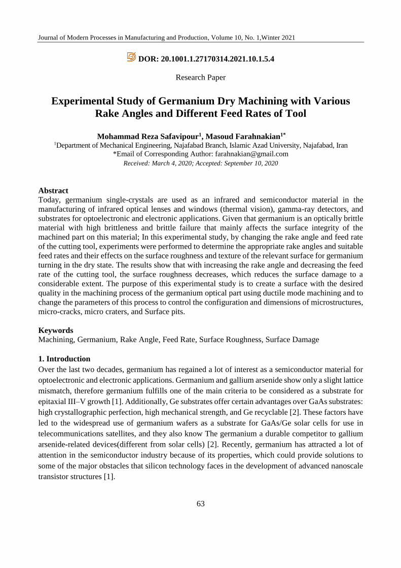
In this experiment, a germanium optical piece with a diameter of 32 mm and a thickness of 2.5 mm
was used, which was embedded on an aluminum fixture made according to Figure3 using a heat-
softened adhesive.
Journal of Modern Processes in Manufacturing and Production, Volume 10, No. 1, Winter 2021
67
Figure 3. Sample of machined germanium and embedded in the relevant fixture
2.1.2 Cutting tool material and dimensions
The tools used in diamond turning are made using different types of diamonds in various types. The
cutting tool was used in the desired tests of insert type, lathe with polycrystalline diamond, and nose
radius of 0.85 mm. Natural or synthetic single-crystal and polycrystalline diamond tools are used in
many machining applications due to their strength and abrasion resistance, depending on the type of
workpiece and the relevant machining parameters.
The experiments were cut by changing the negative rake angle of the tool in 6 different directions
with a clearance angle of approximately 15 degrees as shown in Figure4 a for all tests based on what
is shown in Table1 with a constant rotational speed and variable feed rate.
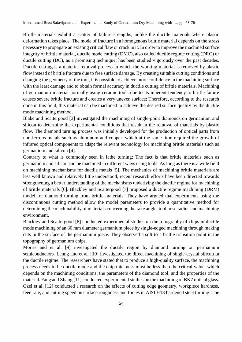
Figure 4. Image of the tool used in the experimental experiment by the VMS machine. a) Tool nose radius. b)
Clearance angle of the tool
To measure the radius of the tool nose by inserting the image obtained from the tool nose by the
optical microscope of the Video Measurement System in Catia software and drawing three lines
tangent to the edges of the tool as shown in Figure4a; Tangent circles were drawn on these drawing
lines using the Tri tangent circle command, and then the actual radius of the instrument was measured
exactly from the surface with the actual dimensions of the instrument at a magnification of 17.5X.
2.1.3 Setup of experimental experiments
Turning of germanium part on NC lathe model TN50D and tool holder made according to Figure5 in
6 test categories to measure the effective negative rake angles as well as the effect of different feed
rates on the roughness and texture of the surface, machining was performed. Cutting this optical piece
in the dry state facilitates the collection of the obtained chips and their recycling.
(b) (a)

Mohammad Reza Safavipour et al, Experimental Study of Germanium Dry Machining with …, pp. 63-76
68
Figure 5. NC lathe and tool holder used in the experimental test
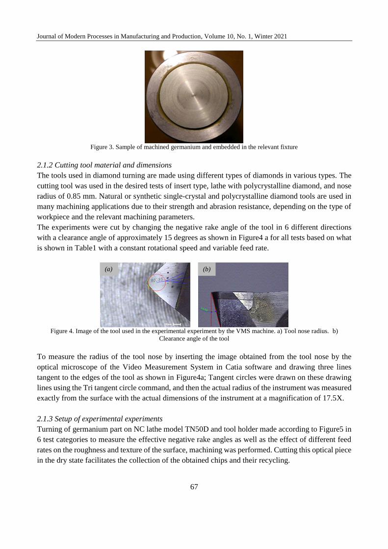
The surface roughness of the samples was measured using the HOMMELWERKE roughness tester
in Figure6, which is an example of the surface roughness diagram measured in Figure7. Also, surface
damage detection was performed by observing the machined surfaces under the optical microscope
of the video measurement system (VMS) in Figure8 with a magnification of 112.5X.
Figure 6. HOMMELWERKE surface roughness measuring device
Figure 7. Sample roughness diagram of the measured surface (single test) with a feed of 50μm/rev from the turning tool,
cutting depth 50 microns from the surface of the germanium sample for a length of 5 mm of the cutting material
Journal of Modern Processes in Manufacturing and Production, Volume 10, No. 1, Winter 2021
69
Figure 8. Optical microscope video measurement system
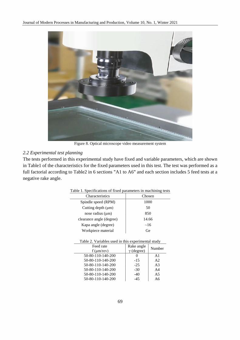
2.2 Experimental test planning
The tests performed in this experimental study have fixed and variable parameters, which are shown
in Table1 of the characteristics for the fixed parameters used in this test. The test was performed as a
full factorial according to Table2 in 6 sections "A1 to A6" and each section includes 5 feed tests at a
negative rake angle.
Table 1. Specifications of fixed parameters in machining tests
Chosen Characteristics
1000 Spindle speed (RPM)
50 Cutting depth (μm)
850 nose radius (μm)
14.66 clearance angle (degree)
~16 Kapa angle (degree)
Ge Workpiece material
Table 2. Variables used in this experimental study
Number Rake angle
γ (degree)
Feed rate
f (μm/rev)
A1 0 50-80-110-140-200 A2 -15 50-80-110-140-200
A3 -25 50-80-110-140-200
A4 -30 50-80-110-140-200
A5 -40 50-80-110-140-200
A6 -45 50-80-110-140-200

Mohammad Reza Safavipour et al, Experimental Study of Germanium Dry Machining with …, pp. 63-76
70
3. Results and Discussion
3.1 surface texture
Machined surfaces according to Table2 in 6 test rows and five feed levels to evaluate the rake angles
in which the machined surfaces have a more intact surface texture in terms of microcracks, bumps,
micro craters, and surface pits were investigated that the images of each machining level are presented
in Tables3.
The surfaces of machined germanium parts according to Table3 in feed 200μm/rev in test number1
have a lot of bumps, micro-cracks, micro craters, and surface pits and represent a very uneven surface
which decreases with feed from 200μm/rev to 110μm/rev, surface damage is reduced by
approximately 23%; Then, by increasing the rake angle in the negative direction of 15 degrees, the
surface damage in the same feed of 200μm/rev is reduced by approximately 18% in test A2 compared
to test A1.
Surface damage in the A3 test with a negative chip angle of 25° in the feed rate changing from
200μm/rev to 140μm/rev has been reduced by approximately 12%, that this process of reducing
surface damage by changing the feed from 140μm/rev to 110μm/rev is approximately equal to 29%.
In total, the surface events in the A4 test compared to A3 with feeds of 200, 140, 110, 80, and
50μm/rev are approximately 14%, 7%, 11%, 26%, and 29%, respectively that is a reducing approach.
In test A4, surface damage with feeds of 200, 110, and 80μm/rev was reduced by approximately 22%,
6%, and 17% compared to test A2, respectively. The trend of reduction of surface damage in test A6
compared to test A4 is approximately 22%, 17%, and 27% in feeds of 200, 110, and 80μm/rev
respectively.
Table3: Surface texture of machined germanium pieces in feed rates of 200 to 50μm/rev with different rake angles
f=50μm/rev f=80μm/rev f=110μm/rev f=140μm/rev f=200μm/rev Test
number
A1
A2
A3
11
2.5
X
200μm

Journal of Modern Processes in Manufacturing and Production, Volume 10, No. 1, Winter 2021
71
A4
A5
A6
The surface damage of machined parts made of germanium material in test A1 according to Table3
in feed 50μm/rev compared to feed 80μm/rev has been reduced by almost 10% that indicated surface
damage in test A2 compared to test A1 with The 50 and 80μm/rev feeds were reduced by
approximately 65% and 53%, respectively.
Surface damage in the A5 test with a negative rake angle of 40 degrees in reducing the feed rate from
200μm/rev to 140μm/rev has been reduced by approximately 15%, this process of reducing surface
damage by changing the feed from 140μm/rev to 110μm/rev is approximately equal to 18%. In total,
the surface events in the A6 test compared to the A5 with feeds of 200, 140, 110, 80, and 50μm/rev
are approximately 10%, 4%, 11%, 9%, and 20% reducing respectively.
According to Table3 in the A4 test compared to A2, the surface damage is approximately 17% and
25% reduction for 80 and 50μm/rev feeds, respectively. The reduction in surface damage in the A6
test compared to the A4 with feeds of 80 and 50μm/rev is approximately 27% and 33%, respectively.
3.1 surface roughness
The surface roughness was measured in 6 test sets "A1 to A6" for 2.5 mm of each surface for initial
examination in the detection of rake angle, and the average surface roughness Ra was recorded for
each test. The diagrams in Figures9 to Figures11 show the roughness Ra for each negative rake angle
and the corresponding feed.
200μm
1
12
.5 X

Mohammad Reza Safavipour et al, Experimental Study of Germanium Dry Machining with …, pp. 63-76
72
Figure 9. Average surface roughness of surface machined from experimental tests for each feed in test group A1 with
zero degree rake angle and in test group A2 with negative rake angle of 15 degrees
According to Figure9, the percentage of changes in average surface roughness Ra at a zero-degree
rake angle of intersection from the feed of 50 to 80μm/rev is approximately equal to 13%, which from
a feed of 80 to 110μm/rev the changes in the roughness of Ra is approximately 8% of a uniform
upward trend. Finally, from a feed of 110 to 200μm/rev, the average surface roughness of the Ra
increased dramatically by approximately 54% by a difference of 0.46μm.
The percentage increasing in the average surface roughness Ra for a -15° rake angle in Figure9 from
a feed of 50 to 80μm/rev is approximately 38%. In the feed of 80 to 200μm/rev, the increasing rate
of Ra roughness is reduced, and the percentage of increase of Ra roughness in the above feed range
is approximately equal to 24%.
According to Figure9, the highest and lowest differences in Ra roughness occurred at the feeds 200
and 110μm/rev for the zero-degree and -15degree rake angles, indicating approximately 32%
reduction in Ra roughness for the -15degree rake angle relative to zero degrees rake angle with a feed
of 200μm/rev; Also, the minimum reduction of Ra roughness in the feed of 110μm/rev for A2 test
compared to A1 test is approximately equal to 6%.
Journal of Modern Processes in Manufacturing and Production, Volume 10, No. 1, Winter 2021
73
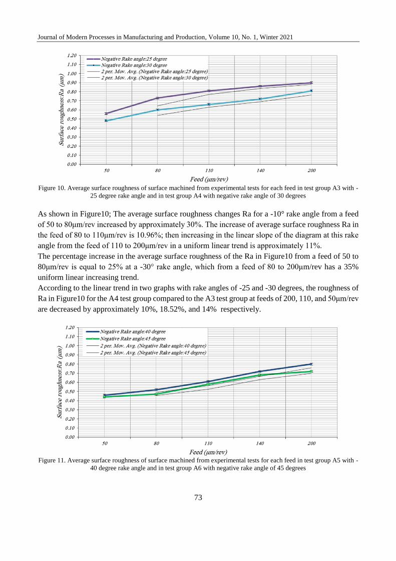
Figure 10. Average surface roughness of surface machined from experimental tests for each feed in test group A3 with -
25 degree rake angle and in test group A4 with negative rake angle of 30 degrees
As shown in Figure10; The average surface roughness changes Ra for a -10° rake angle from a feed
of 50 to 80μm/rev increased by approximately 30%. The increase of average surface roughness Ra in
the feed of 80 to 110μm/rev is 10.96%; then increasing in the linear slope of the diagram at this rake
angle from the feed of 110 to 200μm/rev in a uniform linear trend is approximately 11%.
The percentage increase in the average surface roughness of the Ra in Figure10 from a feed of 50 to
80μm/rev is equal to 25% at a -30° rake angle, which from a feed of 80 to 200μm/rev has a 35%
uniform linear increasing trend.
According to the linear trend in two graphs with rake angles of -25 and -30 degrees, the roughness of
Ra in Figure10 for the A4 test group compared to the A3 test group at feeds of 200, 110, and 50μm/rev
are decreased by approximately 10%, 18.52%, and 14% respectively.
Figure 11. Average surface roughness of surface machined from experimental tests for each feed in test group A5 with -
40 degree rake angle and in test group A6 with negative rake angle of 45 degrees

Mohammad Reza Safavipour et al, Experimental Study of Germanium Dry Machining with …, pp. 63-76
74
As shown in Figure11; the average surface roughness of the Ra from the feed of 50 to 80μm/rev at
the -40 degree rake angle of the "A5 test group" has increased by 13 percent, and this increasing trend
for the roughness of the Ra from the feed from 80 to 200μm/rev is approximately 54 percent.
The average surface roughness of the Ra in Figure11 for the -45° rake angles "A6 test group" is
increasing from a feed of 50 to 80μm/rev with a slight slope of only about 7%, therefore the feed of
50 and 80μm/rev can be a good choice for turning of the germanium material. The angle of inclination
of the changes relative to the horizon line in the A6 test group has increased from a feed of 80 to
140μm/rev, and the percentage increase in Ra roughness in this feed range is approximately 45%.
The trend of changes in the average surface roughness of the Ra from the feed of 140 to 200μm/rev
in the A6 test group "Figure (11)" is approximately only 6%.
According to the results obtained in the average surface roughness of the Ra compared to the feeds
tested in the two test categories A5 and A6, using tools at a 45°negative rake angle compared to a -
40° is recommended.
The percentage of changes of the average surface roughness of the Ra in Figure12 for different rake
angles with different feeds in test groups A2 to A6 compared to the rake angle of zero degrees in test
group A1 can be seen as a bar chart.
Figure 12. Percentage changing of decreasing in the average surface roughness Ra for each category of experiments
compared to experiment A1
The bar chart in Figure12 shows the percentage change from the reduction of Ra roughness in each
test group compared to the first experimental group. At a negative rake angle of 15 degrees "test
group A2" with feeds 50, 80, 110, 140, and 200μm/rev, the Ra roughness reduction compared to its
peer tests at a zero-degree rake angle "A1 test group" equal to 25.71, 8.9, 5.9, 10.4 and 32.0 percentage
are indicated.
According to Figure12 after the A3 test, by increasing the rake angle in the negative direction, the
percentage change from the reduction of Ra roughness has increased significantly as in the rake angles
of 30, 40 and 45 degrees with feeds of 50, 80, 110 and 200μm/rev, the percentage of changes from
the reduction of Ra roughness for each test row in the above three rake angles compared to the zero-

Journal of Modern Processes in Manufacturing and Production, Volume 10, No. 1, Winter 2021
75
degree rake angle are equal to (31.4%, 34.3%, 37.2%), (24.0%, 34.2%, and 40.5%),(22.4%, 28.3%,
and 31.8%) and (38.2%, 39.0%, and 45.0%) respectively.
4. Conclusions
Based on the surface morphology in the performed experiments, in general, by increasing the rake
angle in the negative direction, the surface damages including fractures, micro-cracks, micro craters,
and surface pits in the produced surface are reduced.
Surface damage at rake angles of -15°, -30° and -45° was reduced at feed rates of 50, 80, and
110μm/rev from the tool compared to feeds greater than 110μm/rev at 50μm cutting depth.
The average surface roughness reduction of the Ra compared to the -15° rake angle with the 0° rake
angle at 50μm cutting depth for 50 and 200μm/rev feeds is approximately 26% and 32%, respectively.
The process of reducing the roughness of Ra for comparing the rake angle -30° to zero-degree rake
angle at a cutting depth of 50μm for 50 and 200μm/rev feeds is approximately 32% and 38%,
respectively.
The lowest reduction in average surface roughness of the Ra occurred at two feeds of 50 and
200μm/rev, approximately 20 and 31%, respectively, compared to the -25° rake angle relative to the
0° rake angle; Also, the maximum amount of Ra roughness in two feeds of 50 and 200μm/rev is
approximately equal to 37 and 45%, respectively, for comparing a -45 degree rake angle with zero
degrees rake angle.
5. References
[1] Claeys, C. and Simoen, E. 2011. Germanium-based technologies: from materials to devices.
Chapter 1: Germanium Materials. Elsevier, 11-40.
[2] Derluyn, J., Dessein, K., Flamand, G., Mols, Y. Poortmans, J. Borghs, G. and Moerman, I. 2003.
Comparison of MOVPE grown GaAs solar cells using different substrates and group-V
precursors. Journal of Crystal Growth. 247(3-4): 237-244.
[3] Blake, P.N. and Scattergood, R.O. 1990. Ductile-Regime Machining of Germanium and Silicon.
Journal of the American Ceramic Society. 73(4): 949-957.
[4] Krauskopf, B. 1984. Diamond turning: reflecting demands for precision. Manufacturing
Engineering. 92(5): 90-100.
[5] Shaw, M.C. 1987. Metal Cutting Principles. Oxford University Press, Oxford, NewYork, USA.
[6] Bifano, T.G., Dow, T.A. and Scattergood, R.O. 1991. Ductile-Regime Grinding: A New
Technology for Machining Brittle Materials. Journal of Engineering for Industry. 113(2): 184-189.
[7] Blackley, W.S. and Scattergood, R.O. 1991. Ductile regime model for diamond turning of brittle
materials. Precision Engineering. 13(2): 95–103.
[8] Blackley, W.S. and Scattergood, R.O. 1994. Chip topography for ductile-regime machining of
germanium. Journal of Engineering for Industry. ASME, 116(2): 263-266.
[9] Morris, J.C., Callahan, D.L., Kulik, J., Patten, J.A. and Scattergood, R.O. 1995. Origins of the
Ductile Regime in Single-Point Diamond Turning of Semiconductors. Journal of the American
Ceramic Society, 78(8): 2015-2020.

Mohammad Reza Safavipour et al, Experimental Study of Germanium Dry Machining with …, pp. 63-76
76
[10] Leung, T.P., Lee, W.B. and Lu, X.M. 1998. Diamond turning of silicon substrates in ductile-
regime. Journal of materials processing technology. 73(1-3): 42-48.
[11] Fang, F.Z. and Zhang, G.X. 2004. An experimental study of optical glass machining.
International Journal of Manufacturing Technology. 23(3-4): 155-160.
[12] Özel, T., Hsu, T.K. and Zeren, E. 2005. Effects of cutting edge geometry, workpiece hardness,
feed rate and cutting speed on surface roughness and forces in finish turning of hardened AISI H13
steel. The International Journal of Advanced Manufacturing Technology. 25(3): 262-269.
[13] Yan, J., Takahashi, Y., Tamaki, J.I., Kubo, A., Kuriyagawa, T. and Sato, Y. 2006. Ultra-precision
machining characteristics of poly-crystalline germanium. JSME International Journal Series C
Mechanical Systems, Machine Elements and Manufacturing, 49(1): 63-69.
[14] Stephenson, D. A. and Agapiou, J. S. 2006. Metal Cutting Theory and Practice. 2nd ed., CRC
Press, Taylor and Francis Group, Florida, USA.
[15] Arefin, S., Li, X. P., Rahman, M., and Liu, K. 2007. The upper bound of tool edge radius for
nanoscale ductile mode cutting of silicon wafer. The International Journal of Advanced
Manufacturing Technology. 31(7-8): 655-662.
[16] Pawase, P., Brahmankar, P.K., Pawade, R.S. and Balasubramanium, R. 2014. Analysis of
machining mechanism in diamond turning of germanium lenses. Procedia Materials Science.
Elsevier, 5: 2363-2368.
[17] Kovalchenko, A.M. and Milman, Y.V. 2014. On the cracks self-healing mechanism at ductile
mode cutting of silicon. Tribology International. 80: 166-171.
[18] Zhang, S.J., To, S., Wang, S.J. and Zhu, Z.W. 2015. A review of surface roughness generation
in ultra-precision machining. International Journal of Machine Tools and Manufacture. 91: 76-95.
[19] Farahnakian, M., Keshavarz, M.E., Elhami, S. and Razfar, M.R. 2016. Effect of cutting edge
modification on the tool flank wear in ultrasonically assisted turning of hardened
steel. Proceedings of the Institution of Mechanical Engineers, Part B: Journal of Engineering
Manufacture. 233(5): 1472-1482.
[20] Gupta, S., Khatri, N., Karar, V. and Dhami, S.S. 2016. Investigation of Surface Roughness of
Single Point Diamond Turned Germanium Substrate by Coherence Correlation Interferometry and
Image Processing. IOP Conference Series: Materials Science and Engineering. 149(1): 012032.
[21] Huang, P. and Lee, W.B. 2016. Cutting force prediction for ultra-precision diamond turning by
considering the effect of tool edge radius. International Journal of Machine Tools and
Manufacture. 109: 1-19.
[22] Bai, J., Bai, Q., Chao, Hu., Xin, H. and Pei, X. 2018. Research on the ductile-mode machining
of monocrystalline silicon using polycrystalline diamond (PCD) tools. The International Journal
of Advanced Manufacturing Technology. 94(5-8): 1981-1989.