experimental study of local extinction mechanisms on a...
TRANSCRIPT

18th International Symposium on the Application of Laser and Imaging Techniques to Fluid Mechanics・LISBON | PORTUGAL ・JULY 4 – 7, 2016
Experimental study of local extinction mechanisms on a spray jet flame
A. Verdier*, J.Marrero Santiago, A.Vandel, G.Godard, G.Cabot, M.A. Boukhalfa and B.Renou CORIA-UMR6614
Normandie Université, CNRS, INSA et Université de Rouen 76800 Saint Etienne du Rouvray
France * Correspondent author: [email protected]
Keywords: High-speed OH-PLIF, Spray jet flame, Flame extinctions, PDA
ABSTRACT
This paper presents high-speed (HS) images of OH-PLIF collected at a repetition rate of 10 kHz along the entire
length of an n-heptane spray jet flame. The experimental set-up is composed of an annular non-swirled air co-flow
that surrounds a central hollow-cone spray injector, leading to a stable flame with well-defined boundary
conditions. The experiments include accurate measurements of droplet size (PDA), droplet and carrier phase
velocity (PDA) and two-dimensional flame structure (OH-PLIF). The polydisperse spray distribution yields small
droplets along the centerline axis while the majority of the mass is situated as big droplets along the spray borders.
The flame structure presents a classical shape, with an inner wrinkled partially premixed flame front and an outer
diffusion flame front. Although the High Speed (HS)-OH-PLIF images are only qualitative, they are found to be a
sufficient spatial and temporal resolution to relay the dynamics of extinctions events. Applying data processing
tools and coupling with aerodynamics results allowed to highlight different extinctions mechanisms. In the inner
reaction zone the measured speed, as well as the turbulent kinetic energy, showed that the large turbulence scales
played a significant role in the dynamics of extinction. However; the locally extinction in the outer reaction zone can
be attributed to the big droplets that present a skin term for the flame.
1. Introduction
Spray combustion involves many complex physical phenomena, including atomisation,
dispersion, evaporation and combustion, which generally take place simultaneously or within
very small regions in the combustion chambers. Although numerical simulation is a valuable
tool to tackle these different interactions between liquid and gas phases, the method needs to be
validated through reliable experimental studies. Therefore, accurate experimental data on flame
structure and on liquid and gas properties along evaporation and combustion steps are needed.
These experiments also allow to provide a physical understanding of fuel droplet interaction
with the flame structure in real and representative two-phase flow configurations, in the
perspective of moving forward into more complex configurations (aeronautical, gas turbine, …).

18th International Symposium on the Application of Laser and Imaging Techniques to Fluid Mechanics・LISBON | PORTUGAL ・JULY 4 – 7, 2016
The spray jet flame is a canonical configuration which presents the essential feature of very well
defined boundary conditions. The flame topologies are representative of those obtained in real
burners with 3D complex flow motions (swirl or bluff-body), including a large distribution of
droplet sizes and different combustion regimes. The simulation of these geometries is a complex
task since it requires at least an accurate prediction of the fuel vapour and the thermal budget
between the droplet and its gaseous surrounding through the evaporation model, and a detailed
description of the combustion reactions able to predict the different modes of combustion (Ma,
Naud et al. 2015). The spray jet flame has already been experimentally investigated including
studies on the flame structure (Cessou and Stepowski 1996; Friedman and Renksizbulut 1999;
Marley, Welle et al. 2004; Cléon, Honoré et al. 2015; Correia Rodrigues, Tummers et al. 2015) or
the stabilisation of the edge-flame (Marley, Welle et al. 2004; Cléon, Honoré et al. 2015).
However, one of the fundamental aspects to consider in turbulent two-phase combustion is the
strong interactions between the chemical reaction, the turbulence field and the droplets which
occur during the vaporisation and combustion processes. For instance, the turbulence can
amplify local heat releases which greatly influence the flame by momentum, heat and mass
transfer. The rate of change in the spatial flame structure due to scalar dissipation rates and local
variations in the mixing zone can induce extinctions events (Kaiser and Frank 2009). With the
improvement of the high repetition rates, the high speed diagnostics can temporarily resolve the
scalars in turbulent flows. These efforts have yielded a greater understanding of dynamic
turbulent flame behaviour through tracking the temporal evolution of transient phenomena such
as local extinction, auto-ignition and turbulence-chemistry interactions (Boxx, Stöhr et al. 2009;
Boxx, Arndt et al. 2010; Abram, Fond et al. 2013; Slabaugh, Pratt et al. 2015). Besides, the
previous work on the extinction phenomena, in a turbulent spray jet flame the situation is more
complex and an understanding of extinction mechanisms need to be studied.
The present experimental study focuses on the detailed characterization of extinction
mechanisms along the combustion phases in an n-heptane spray jet flame by applying high
speed optical diagnostics. The local properties of flow as spray droplet dispersion, size, velocity
and the carrier phase velocity are obtained by Phase Doppler Anemometry (PDA) and by
Particle Tracking Velocity (PTV). High Speed OH-PLIF (HS-OH-PLIF) is used to time-resolve the
flame dynamics and in particular the transient phenomena as local extinction. Three mechanisms
of extinctions in three different zones are identified and further analysed in detail using a
specific methods for processing images.

18th International Symposium on the Application of Laser and Imaging Techniques to Fluid Mechanics・LISBON | PORTUGAL ・JULY 4 – 7, 2016
2. Experimental approach
2.1. Experimental facility
Experiments are carried out in an atmospheric and open burner based on the geometry of the
gaseous KIAI burner (Cordier, Vandel et al. 2013) (Fig. 1). The fuel injection system is composed
of a simplex fuel injector (Danfoss, 1.35 kg.h-1, 80°, hollow cone) and an external annular, non-
swirling air co-flow, with an inner and outer diameter of 10 and 20 mm respectively. Air and
liquid fuel (n-heptane) mass flow rates are controlled by thermal and Coriolis mass flow
controllers. The inlet conditions of air and fuel are 6 g.s-1 (T=298 ± 2 K) and 0.28 g.s-1 (T=298 ± 2
K) respectively, which leads to an air bulk velocity of 19.9 m.s-1. In Fig. 1, X and Z represent the
radial and axial coordinates, respectively.
Fig. 1: Detail of the injection system and typical flame picture when the flow is illuminated by a Nd:YAG laser sheet
2.2 Optical diagnostics
A schematic of the high-speed OH-PLIF imaging set-up is shown in Fig. 2. In this paper, OH-
signal is used as a marker of the reaction zone so a breakage in the OH profile is deemed to mark
local extinction. A Nd-YAG-laser operating at 532 nm (with a power of 104 W) is used to pump a
tunable dye laser (Sirah Credo). The resultant output pulse energy is 380 µJ per shot in the probe
volume. The excitation wavelength is tuned to the Q1(5) transition of the ∑
← ∏ band of OH at λ =282.665 nm. The beam is then expanded to 35mm in height
using a diverging cylindrical lens before being focused into a sheet using a focused with a 200
mm focal length. Due to the low energy delivered, the detection system consists of a CMOS-
camera Photron Fastcam SA5 mounted with an external image intensifier (High Speed IRO,
ZX
Air inlet
Fuelinlet

18th International Symposium on the Application of Laser and Imaging Techniques to Fluid Mechanics・LISBON | PORTUGAL ・JULY 4 – 7, 2016
Lavision) equipped with UV lens (f/2). The camera has been run at a repetition rate of 10 kHz
with an array of 896 x 848 pixels and an image resolution of 500 μm/pixel. Intensifier delay (2900
ns) and gate (200 ns) are set to optimize the signal to noise ratio. Background noise arising from
elastic scattering by the droplets is reduced with two high-pass optical filters (Schott WG295).
The camera on-board memory can hold over 7500 frames, corresponding to an acquisition time
of 750 ms. The OH-PLIF signals are collected using a broadband collection strategy from 308 to
330 nm with a band-pass filter (Schott UG11). Moreover, the laser sheet profile is taken into
account and corrected by filling the test facility with a homogeneous mixture of air/acetone in
the quartz plate. Besides the presence of droplets in the field of view, the signal to noise ratio is
really good and varied between 100 and 150.
Fig. 2 : Optical arrangement for high-speed OH-PLIF measurements.
Droplet size and velocity are characterised by a commercial PDA system (DANTEC) operating
in DUAL mode with 50° front-scattering probes. An argon laser provides green (514.5 nm) and
blue (488 nm) beams. Beam spacing is 50 μm; the focal length of the transmitting lenses is 350
mm, and the focal length of the receiving optics is 310 mm. The used aperture mask allows a
detection diameter range of 139 μm. The measurement volume can be approximated by a
cylinder of 120 μm in diameter and 200 μm in length. At each measurement location, data
sampling is limited to 40,000 droplets or to 30s of measuring time, allowing converged statistics
of size-classified data. Due to the spray structure and particle concentration distribution, the
measurements are not possible below z = 10 mm. Besides the spray characterization, the carrier
phase velocity is also investigated by seeding the co-flow with 2.5 μm olive oil droplets.
FILTER
(UG11 / WG295x2)
282,65 nm
PU
MP
LA
SE
RN
d-Y
AG
53
2n
m
DYE LASER
SIRAH
CREDO
CAMERA
Intensifier

18th International Symposium on the Application of Laser and Imaging Techniques to Fluid Mechanics・LISBON | PORTUGAL ・JULY 4 – 7, 2016
2.3 Data processing
The objective of this study is to understand the extinction mechanisms in a spray jet flame. Due
to the huge amounts of data resulting from high-speed imaging, it is necessary to use an
automatic image-processing to extract several results. A pre-processing is applied to normalize
raw images and can be divided into two steps. First, it is the background correction which allow
to subtract the reflexions and electronic noise from the camera intensifier by averaging 500
images, recorded when the experiment is switched off but with the laser beam. Due to the non-
homogeneous energy distribution in the laser beam, the signal fluorescence is artificially
modulated. It is possible to have access to the mean laser sheet profile, to correct these spatial
energy variations, with filling a region of acetone vapor and by averaging 1000 images. Finally,
the pre-processing steps can be summarized with the following equation:
(1)
Where is the corrected images, is the raw images, is the mean laser profile
and is the mean backroung image.
An image-processing tool is developed to automate the flame front detection with a Non Linear
Diffusion (NLD) filter to reduce the level of noise and to enhance gradients in the images. The
method is based on the original appoach formulated by Perona and Malik (Perona and Malik
1990) and has several advantages: (i) Noise is smoothed locally within regions defined by object
boundaries, whereas little or no smoothing occurs between image objects. (ii) Local edges are
enhanced because discontinuities, such as boundaries, are amplified (Malm, Sparr et al. 2000;
Hartung, Hult et al. 2009).
A traditional way to smooth an image is to convolve it with a Gaussian Kernel and resolve the
solution of the linear diffusion equation:
(2)
Perona and Malik (Perona and Malik 1990) proposed to exchange the constant scalar diffusion
in Eq. (2) for a scalar-valued function of the gradient of the gray image. The diffusion
equation is now written by the following equation:

18th International Symposium on the Application of Laser and Imaging Techniques to Fluid Mechanics・LISBON | PORTUGAL ・JULY 4 – 7, 2016
[ | | ]
(3)
The diffusivity function g is a monotonically decreasing function which is responsible for the
edge preservation. Perona and Malik (Perona and Malik 1990) proposed two different diffusivity
functions:
| |
| |
(4)
| | (
| |
)
(5)
It is found that the NLD filters use with Eq. (4) demonstrate a good ability to preserve the flame
front edges without artificial shifting in position (Han, Cai et al. 2014). In the present
experimental study a NLD filter with a diffusivity function equal to Eq. (4) is chosen and results
are represented in Fig. 3.
Fig. 3 (a) Image corrected by pre-processing. (b) Image filtered by NLD. (c) Comparison between raw and NLD
profiles.
Numerically, a semi-implicit iterative scheme is implemented and executed in parallel in Matlab
software. It is an excellent compromise between computational cost and filter performance. Then
active contour models are used to obtain the curves that most accurately describe the flame front.
These curves are obtained using the concept of geodesic path computation. The level set
representation is employed; even complex curve evolutions including those with topological
changes in their structures can be handled. The geodesic active contour model is introduced by
Caselles et al. (Caselles, Catté et al.).
(a) (b) (c)

18th International Symposium on the Application of Laser and Imaging Techniques to Fluid Mechanics・LISBON | PORTUGAL ・JULY 4 – 7, 2016
This approach is equivalent to find geodasic distance of two points. The idea behind the level set
method is to imbed a curve within a surface and to solve the Eq. (6). The first step is to specify an
initial guess for the contour, which is then moved by image driven forces boundaries of the
desired objects. In our models, two types of forces are considered. The internal forces are
designed to keep the model smooth during the deformation process, while the external forces,
which are computed from the underlying image data, are defined to move the model toward an
object boundary or other desired features within the image.
| | (
| |) | |
(6)
Fig. 4: (a) Representation of Φ (Eq. 6) and initial contour for the level set. (b) Image filtered by NLD and final
contour obtained by level set method.
A representation of Φ with the initial contour is plotted in Fig. 4a. As described below, the final
contour (Fig. 4b) is obtained when the function Φ is equal to zero. From the extract contour,
plenty of information can be obtained as the curvature.
Moreover, to improve the droplet-flame front interactions, a Particle Tracking Velocimetry (PTV)
is used, in the corrected images, to determine the velocity and the trajectory associated to
individual droplet in the spray jet flame. The method works in a Langrangian frame of reference.
PIV calculates the associated velocity to group tracer particles at fixed spatial positions, while
PTV, depending on the experimental conditions, allows the determination of the velocity
associated to individual particles trajectories. In order to obtain these results, the PTVlab (Matlab
software) is used (Brevis, Niño et al. 2011). Fig. 5 shows the procedure to extract the velocity and
(b)(a)
18th International Symposium on the Application of Laser and Imaging Techniques to Fluid Mechanics・LISBON | PORTUGAL ・JULY 4 – 7, 2016
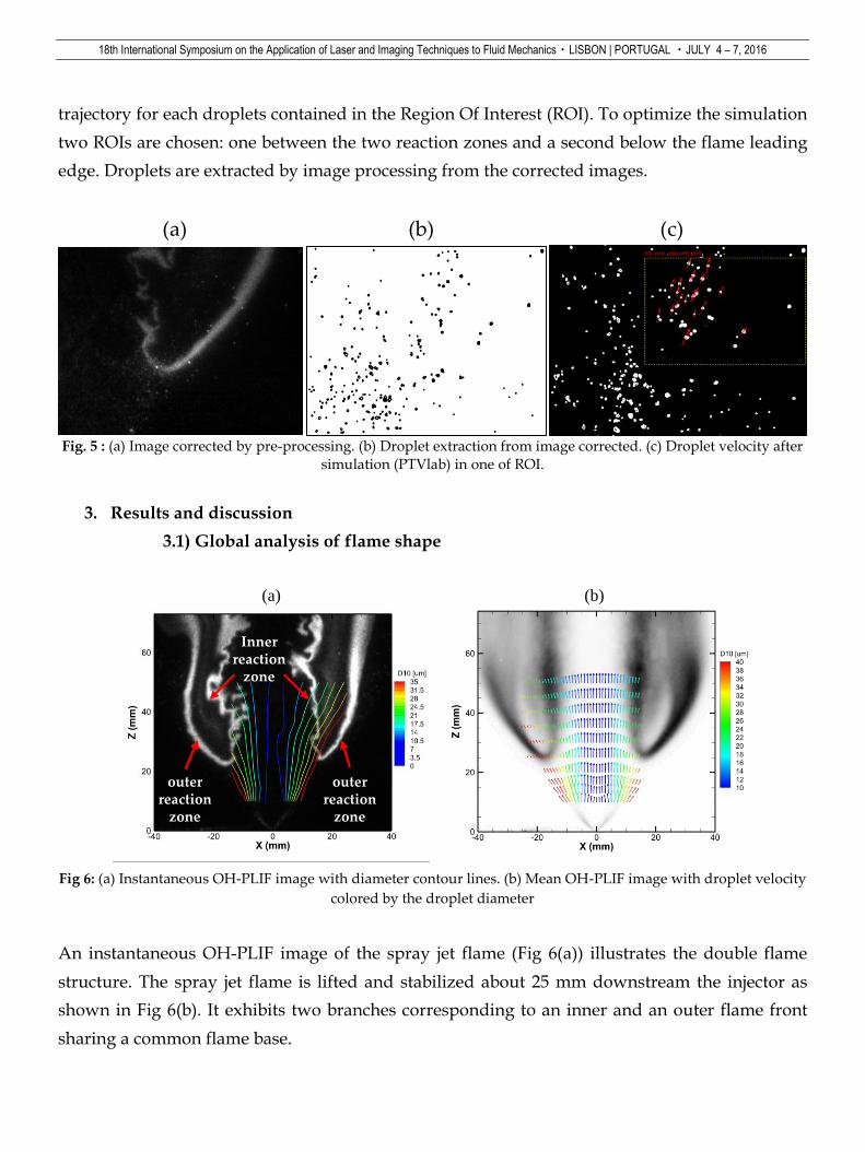
trajectory for each droplets contained in the Region Of Interest (ROI). To optimize the simulation
two ROIs are chosen: one between the two reaction zones and a second below the flame leading
edge. Droplets are extracted by image processing from the corrected images.
Fig. 5 : (a) Image corrected by pre-processing. (b) Droplet extraction from image corrected. (c) Droplet velocity after
simulation (PTVlab) in one of ROI.
3. Results and discussion
3.1) Global analysis of flame shape
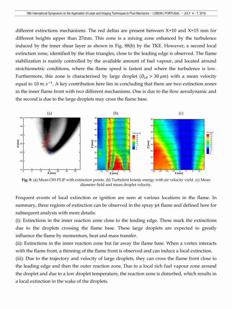
Fig 6: (a) Instantaneous OH-PLIF image with diameter contour lines. (b) Mean OH-PLIF image with droplet velocity
colored by the droplet diameter
An instantaneous OH-PLIF image of the spray jet flame (Fig 6(a)) illustrates the double flame
structure. The spray jet flame is lifted and stabilized about 25 mm downstream the injector as
shown in Fig 6(b). It exhibits two branches corresponding to an inner and an outer flame front
sharing a common flame base.
(a) (b) (c)
(a) (b)
Innerreaction
zone
outerreaction
zone
outerreaction
zone

18th International Symposium on the Application of Laser and Imaging Techniques to Fluid Mechanics・LISBON | PORTUGAL ・JULY 4 – 7, 2016
This flame structure results from the spray heterogeneity in size (Marley, Welle et al. 2004;
Cléon, Honoré et al. 2015; Correia Rodrigues, Tummers et al. 2015), where the large droplets
spread into the outer part of the air co-flow and the ambient air (red lines), and the small
droplets are mainly located in the centre. Indeed, in this region, the very small droplets (blue
lines) represent only a small quantity of the liquid mass and undergo a slow evaporation,
leading to fuel lean mixture, below the lean flammability limit. As shown by the droplet velocity,
the small droplet (blue vectors) mainly stay in the cold central zone and never cross the flame
front. On the contrary the red vectors in Fig 6(b) indicate that large, inertial droplet move to the
external part of the spray, crossing the leading edge and reaching the hot region between the
inner and outer reaction zones.
The inner flame structure is strongly wrinkled and located along the shear layer created by the
air co-flow discharging into the ambient air. Indeed, the mean location of the inner flame is
placed over a high turbulent kinetic energy region of the NRC flow (Fig. 8(b)). It is characterised
by an intense mixing between air co-flow and small droplets at downstream locations, due to
high level of turbulent kinetic energy. In addition to turbulence, the strong variations of
equivalence ratio explain the highly wrinkled shape of the inner reaction zone and its fluctuating
behavior.
Additionally, the inner flame is characterised by a strong OH gradient indicating that
combustion occurs in a partially premixed regime with a flame propagation mechanism. Fuel
droplets are still visible in the vicinity of the inner reaction zone and may have crossed it.
Indeed, these droplets correspond to the large droplets moving to the outer part of the spray as
shown by droplet velocity (red vectors Fig. 8(c)). In the region between the flame fronts, where
weak OH signal is still visible, the high surrounding temperature, due to the combustion,
imposes a fast droplet evaporation. The strong thermal exchange induces an augmentation of the
gaseous fuel mass fraction. This fuel reservoir will react further in the diffusion-like outer flame
front. The outer reaction zone is less wrinkled, more stable, thicker than the turbulent inner
reaction zone, and characterised by a smoother OH gradient.
In the combustion regime, usually a reaction progress variable ( ) is used to describe the
progress of combustion in a flame front. In the fresh gas, the progress variable is conventionally
put to zero. In the burnt gas, it equals to unity. Across the flame, the intermediate values
describe the progress of the reaction to turn into burnt gas the fresh gas penetrating the flame
sheet. A progress variable can be set with the help of any quantity like temperature, reactant
mass fraction, provided it is bounded by a single value in the burnt gas and another one in the
fresh gas.

18th International Symposium on the Application of Laser and Imaging Techniques to Fluid Mechanics・LISBON | PORTUGAL ・JULY 4 – 7, 2016
For instance, c can be written in the following way :
It is seen that c is a normalization of a scalar quantity. The index denotes the burnt gas and
the fresh gas. Experimentally, the mean progress variable is obtained from the binearisation of
the mean of all instantaneous OH-PLIF images (Erreur ! Source du renvoi introuvable.).
Fig. 7: Left side: Mean OH-PLIF image. Right side: Mean progress variable < >
Figure. 7 (right side) indicates that for radial distances smaller than X=4 mm, the droplets are
always present in fresh gas. However, regardless of axial station, at X=20 mm, the droplets will
be in burnt gas.
3.1) Zones of local extinctions in a spray jet flame
The following section concerns the analysis of OH-PLIF results. The high repetition rate is used
to understand the physical phenomena involved in flame dynamics. The field of view is now
equal to 35*35 mm² and chosen to have a good spatial resolution. It is worth noting that PLIF-
OH is used throughout this study as a marker of reaction zone so that a breakage in an otherwise
continuous OH profile is deemed to mark local extinction. The interval between two consecutive
instantaneous OH-PLIF images is equal to 0.1 ms and gives a good time resolution to study the
flame dynamics.
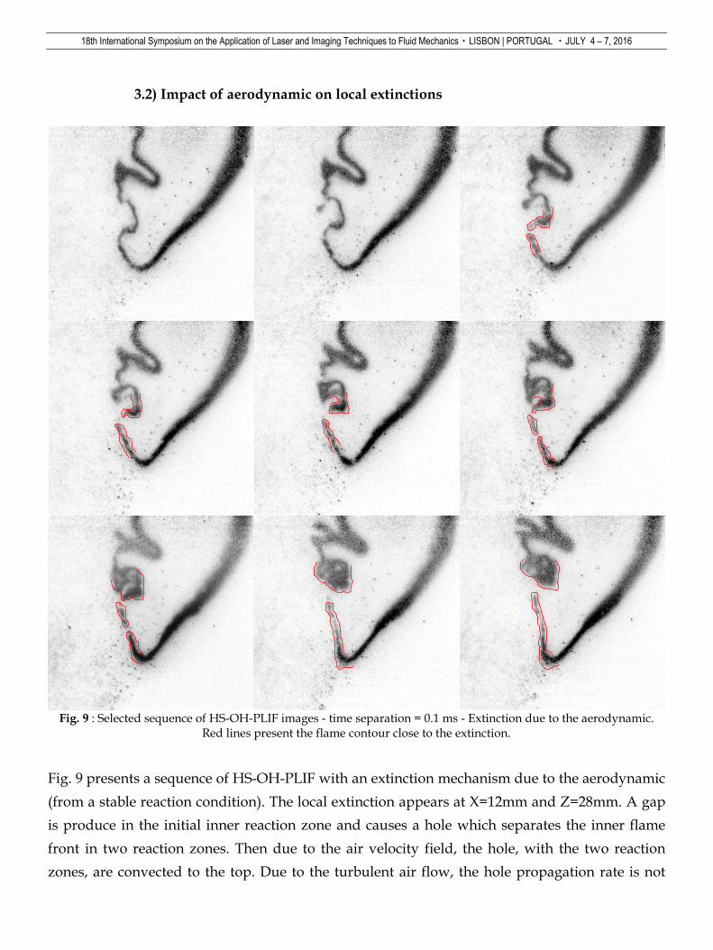
Figure 8(a) shows the mean OH-PLIF with the different extinction zones. These points represent
the first position (X & Z) of extinction. The next point is necessarily obtained after a stable
reaction condition that means a continuous inner reaction zone. 100 extinctions are detected on
1000 instantaneous HS-OH-PLIF. The local extinctions, in the inner reaction, appear in two
regions represented by red deltas and blue triangles. This bimodality implies that they are
18th International Symposium on the Application of Laser and Imaging Techniques to Fluid Mechanics・LISBON | PORTUGAL ・JULY 4 – 7, 2016
different extinctions mechanisms. The red deltas are present between X=10 and X=15 mm for
different heights upper than 27mm. This zone is a mixing zone enhanced by the turbulence
induced by the inner shear layer as shown in Fig. 88(b) by the TKE. However, a second local
extinction zone, identified by the blue triangles, close to the leading edge is observed. The flame
stabilization is mainly controlled by the available amount of fuel vapour, and located around
stoichiometric conditions, where the flame speed is fastest and where the turbulence is low.
Furthermore, this zone is characterised by large droplet ( ) with a mean velocity
equal to . A key contribution here lies in concluding that there are two extinction zones
in the inner flame front with two different mechanisms. One is due to the flow aerodynamic and
the second is due to the large droplets may cross the flame base.
Fig. 8: (a) Mean OH-PLIF with extinction points. (b) Turbulent kinetic energy with air velocity vield. (c) Mean
diameter field and mean droplet velocity.
Frequent events of local extinction or ignition are seen at various locations in the flame. In
summary, three regions of extinction can be observed in the spray jet flame and defined here for
subsequent analysis with more details:
(i): Extinctions in the inner reaction zone close to the leading edge. These mark the extinctions
due to the droplets crossing the flame base. These large droplets are expected to greatly
influence the flame by momentum, heat and mass transfer.
(ii): Extinctions in the inner reaction zone but far away the flame base. When a vortex interacts
with the flame front, a thinning of the flame front is observed and can induce a local extinction.
(iii): Due to the trajectory and velocity of large droplets, they can cross the flame front close to
the leading edge and then the outer reaction zone. Due to a local rich fuel vapour zone around
the droplet and due to a low droplet temperature, the reaction zone is disturbed, which results in
a local extinction in the wake of the droplets.
(a) (b) (c)
18th International Symposium on the Application of Laser and Imaging Techniques to Fluid Mechanics・LISBON | PORTUGAL ・JULY 4 – 7, 2016
3.2) Impact of aerodynamic on local extinctions
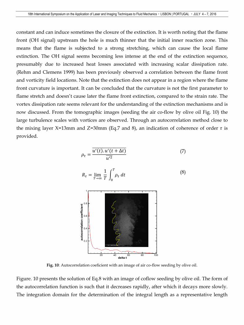
Fig. 9 : Selected sequence of HS-OH-PLIF images - time separation = 0.1 ms - Extinction due to the aerodynamic.
Red lines present the flame contour close to the extinction.
Fig. 9 presents a sequence of HS-OH-PLIF with an extinction mechanism due to the aerodynamic
(from a stable reaction condition). The local extinction appears at X=12mm and Z=28mm. A gap
is produce in the initial inner reaction zone and causes a hole which separates the inner flame
front in two reaction zones. Then due to the air velocity field, the hole, with the two reaction
zones, are convected to the top. Due to the turbulent air flow, the hole propagation rate is not
18th International Symposium on the Application of Laser and Imaging Techniques to Fluid Mechanics・LISBON | PORTUGAL ・JULY 4 – 7, 2016
constant and can induce sometimes the closure of the extinction. It is worth noting that the flame
front (OH signal) upstream the hole is much thinner that the initial inner reaction zone. This
means that the flame is subjected to a strong stretching, which can cause the local flame
extinction. The OH signal seems becoming less intense at the end of the extinction sequence,
presumably due to increased heat losses associated with increasing scalar dissipation rate.
(Rehm and Clemens 1999) has been previously observed a correlation between the flame front
and vorticity field locations. Note that the extinction does not appear in a region where the flame
front curvature is important. It can be concluded that the curvature is not the first parameter to
flame stretch and doesn’t cause later the flame front extinction, compared to the strain rate. The
vortex dissipation rate seems relevant for the understanding of the extinction mechanisms and is
now discussed. From the tomographic images (seeding the air co-flow by olive oil Fig. 10) the
large turbulence scales with vortices are observed. Through an autocorrelation method close to
the mixing layer X=13mm and Z=30mm (Eq.7 and 8), an indication of coherence of order is
provided.
(7)
∫
(8)
Fig. 10: Autocorrelation coeficient with an image of air co-flow seeding by olive oil.
Figure. 10 presents the solution of Eq.8 with an image of coflow seeding by olive oil. The form of
the autocorrelation function is such that it decreases rapidly, after which it decays more slowly.
The integration domain for the determination of the integral length as a representative length

18th International Symposium on the Application of Laser and Imaging Techniques to Fluid Mechanics・LISBON | PORTUGAL ・JULY 4 – 7, 2016
scale of the turbulence can be specified by a frequence way. It is a measure of the longest
correlation time between the flow velocity(vorticity) at two points in the flow field and is equal
in this case to 82Hz.
This means that at a frequency equal to 82Hz, the vortices disturbed the flame front by a high
strain rate and may cause an insufficient momentum transfer to entrain the required air for
sustaining an inner reaction zone. The flame becomes too stretched and the local mixture is
outside the required condition to keep a stable flame front, which causes a local extinction of
inner reaction zone. To validate the hypothesis that it is the large vortices which induce the local
extinctions, an extinction occurrence frequency analysis is done in the inner reaction zone. A
probe volume located in X=16mm and Z=30mm is used to determine the temporal apparition of
extinction. 𝑓 represents the distance between the probe volume and the flame front. The specific
value of 𝑓 represents the position of instantaneous flame front, whereas the negative and
positive values concern the fresh and burnt gases, respectively. The specific values of 𝑓
corresponds to the distance between the probe volume and the outer reaction zone and is
considered here as extinctions. Note that with these previous values of 𝑓 it is possible to show
the low fluctuations of the outer reaction zone. Using a power spectral density function (PSD), a
peak at 78Hz is obtained. This analysis allows concluding that the large turbulence scale
(vortices) modified the flame behavior until sometimes extinction. This analysis allows
concluding that the large turbulence scales (vortices) modify the flame behavior until sometimes
extinguish the reaction zone as illustrated in Fig. 11(c).
Fig. 11: (a) Extinction occurrence temporal analysis. (b) Extinction occurrence frequency analysis. Profile at X=16mm
and Z=30mm. (c) Schematic representation of the extinction due to aerodynamic.
(a) (b)
Hig
h
TK
E
Hig
h
TK
E
Extinction
Innerreaction
zone
Vortices
(c)
18th International Symposium on the Application of Laser and Imaging Techniques to Fluid Mechanics・LISBON | PORTUGAL ・JULY 4 – 7, 2016
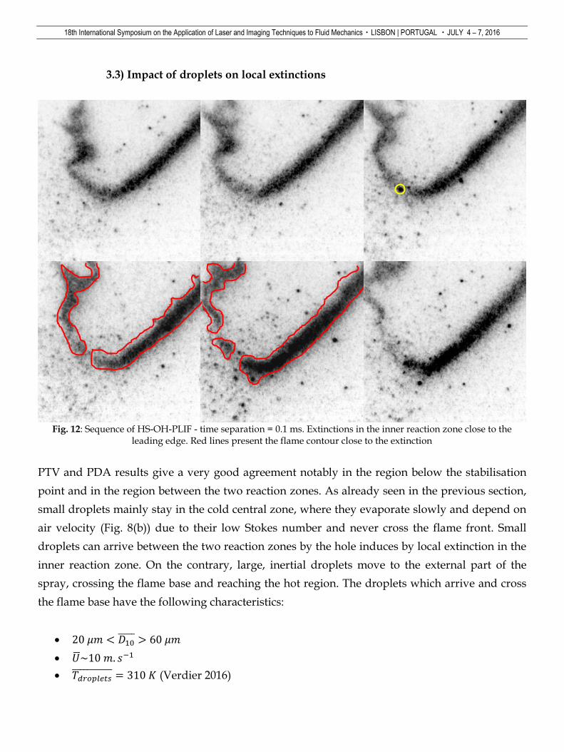
3.3) Impact of droplets on local extinctions
Fig. 12: Sequence of HS-OH-PLIF - time separation = 0.1 ms. Extinctions in the inner reaction zone close to the
leading edge. Red lines present the flame contour close to the extinction
PTV and PDA results give a very good agreement notably in the region below the stabilisation
point and in the region between the two reaction zones. As already seen in the previous section,
small droplets mainly stay in the cold central zone, where they evaporate slowly and depend on
air velocity (Fig. 8(b)) due to their low Stokes number and never cross the flame front. Small
droplets can arrive between the two reaction zones by the hole induces by local extinction in the
inner reaction zone. On the contrary, large, inertial droplets move to the external part of the
spray, crossing the flame base and reaching the hot region. The droplets which arrive and cross
the flame base have the following characteristics:
2 < 6
��~
𝑝 𝐾 (Verdier 2016)

18th International Symposium on the Application of Laser and Imaging Techniques to Fluid Mechanics・LISBON | PORTUGAL ・JULY 4 – 7, 2016
Nevertheless, the flame induces dramatically change in the characteristics of droplets. When
they reaching the immediate vicinity of the flame base (high temperature), their temperature
increase and the strong thermal exchange imposes a fast evaporation regime resulting in a
augmentation of the gaseous fuel mass fraction and so a droplet diameter diminution. It is worth
noting that the flame decelerates the droplet as shown by (Ma and Roekaerts 2016). The mean
characteristics of droplets present between the two reaction zones are:
< 5
��~7
𝑝 𝐾 (Verdier 2016)
Figure. 12 presents a HS-OH-PLIF image sequence, where a big droplet (yellow circle) arrives
with a relative velocity in the leading edge. After the passage of the drop a local extinction,
located at the place where the drop is passed, is visualised. Unlike the rapid extinction
convection that occurs far away in the inner reaction, the closure between the two reaction zones,
to obtain a stable reaction condition, is reach more quickly in this case. This shorter time is due to
local conditions close to the stoichiometry with low turbulence. The hole in the reaction zone
indicates a local quenching due to large heat loss caused by droplet evaporation (Mercier, Orain
et al. 2007). Furthermore, the n-heptane vapour around the droplet induces locally a rich mixture
which can be above to the fuel flammability. Furthermore, the n-heptane vapour around the
droplet induced locally a rich mixture which can be superior to the fuel flammability limit. These
droplet-flame behaviors are observed also in the outer reaction zones.
Fig. 13 shows four different sequences to highlight the droplet impact on the outer reaction zone.
Further downstream, droplets that have survived the flame brush continue through the outer
reaction zone, where they disturb the flame front. In most of the cases (#1, #2 and #4), there are
not extinction in term of discontinuity in the outer OH-PLIF signal. However, the combustion
doesn’t occur in the wake of droplet, this means that the local conditions behind the droplet is
too rich to burn. The major difference between the inner reaction and the outer reaction zone is
the droplets velocity and their temperature. With a lower velocity in the hot region, the time to
cross the outer reaction is longer than for the inner reaction zone.

18th International Symposium on the Application of Laser and Imaging Techniques to Fluid Mechanics・LISBON | PORTUGAL ・JULY 4 – 7, 2016
Fig. 13: 4 different sequences of HS-OH-PLIF - time separation = 0.1 ms. Extinctions in the inner reaction zone close
to the leading edge.
4. Acknowledgements
The financial support provided by ANR TIMBER is gratefully acknowledged.
5. Conclusion
In this paper, a detailed experimental study of turbulence-droplet-chemistry interactions events
in an n-heptane spray jet flame is presented. Although the information is qualitative, the
sequences of High Speed OH-PLIF possess sufficient spatial and temporal resolution allowing
follow the evolution of transient phenomena as local extinctions. The flame exhibits a double
structure with inner and outer reaction zones, where fuel droplets are still present and disturb
the reaction. Droplet size, droplet and carrier phase velocities are preliminary characterised by
PDA, which give information about turbulence field. Two kinds of extinction mechanism in
three different zones, two in the inner reaction (one close the leading edge and a second far away
#1
#2
#3
#4

18th International Symposium on the Application of Laser and Imaging Techniques to Fluid Mechanics・LISBON | PORTUGAL ・JULY 4 – 7, 2016
the flame base), and in the outer reaction zone are identified. In the inner reaction zone far away
the flame base, the temporal evolution of extinction events could thus be correlated to the
behaviour of turbulent velocity field. Indeed, the turbulent flow generates vortices, close to the
shear layer, which greatly influence the flame by momentum, heat and mass transfer. Due to the
large turbulent scales, the flame becomes too stretched and the local mixture is outside the
required condition to keep a stable flame front, which causes a local extinction. The extinction
propagation rate is mainly turbulent and depends on the flow field. The first extinction
mechanism is due to the strong turbulence-chemistry interactions and appear for axial stations
upper to Z=27mm. The second mechanism is related to the droplet-chemistry interactions and
arrives in the flame base and in the outer reaction zone. The big droplets, which have a lower
temperature than in the flame, act as a temperature sink for the flame front which finally
extinguishes due to the cooling effect. In addition, due to the evaporation process, there is a fuel
vapour surrounding the droplet which increases the local equivalence ratio. In the wake of
droplet, it may be possible that the mixture is too rich to burn.
6. References
Abram, C., B. Fond, et al. (2013). "High-speed planar thermometry and velocimetry using
thermographic phosphor particles." Applied Physics B 111(2): 155-160.
Boxx, I., C. Arndt, et al. (2010). "High-speed laser diagnostics for the study of flame dynamics in
a lean premixed gas turbine model combustor." Experiments in Fluids: 1-13.
Boxx, I., M. Stöhr, et al. (2009). "Sustained multi-kHz flamefront and 3-component velocity-field
measurements for the study of turbulent flames." Applied Physics B: Lasers and Optics
95(1): 23-29.
Brevis, W., Y. Niño, et al. (2011). "Integrating cross-correlation and relaxation algorithms for
particle tracking velocimetry." Experiments in Fluids 50(1): 135-147.
Caselles, V., F. Catté, et al. "A geometric model for active contours in image processing."
Numerische Mathematik 66(1): 1-31.
Cessou, A. and D. Stepowski (1996). "Planar Laser Induced Fluorescence Measurement of [ OH]
in the Stabilization Stage of a Spray Jet Flame." Combustion Science and Technology
118(4-6): 361-381.
Cléon, G., D. Honoré, et al. (2015). "Experimental investigation of structure and stabilization of
spray oxyfuel flames diluted by carbon dioxide." Proceedings of the Combustion Institute
35(3): 3565-3572.
Cordier, M., A. Vandel, et al. (2013). "Laser-Induced Spark Ignition of Premixed Confined
Swirled Flames." Combustion Science and Technology 185(3): 379-407.

18th International Symposium on the Application of Laser and Imaging Techniques to Fluid Mechanics・LISBON | PORTUGAL ・JULY 4 – 7, 2016
Correia Rodrigues, H., M. J. Tummers, et al. (2015). "Spray flame structure in conventional and
hot-diluted combustion regime." Combustion and Flame 162(3): 759-773.
Friedman, J. A. and M. Renksizbulut (1999). "Investigating a methanol spray flame interacting
with an annular air jet using phase-Doppler interferometry and planar laser-induced
fluorescence." Combustion and Flame 117(4): 661-684.
Han, Y., G.-B. Cai, et al. (2014). "A conditioned level-set method with block-division strategy to
flame front extraction based on." Chinese Physics B 23(5): 058901.
Hartung, G., J. Hult, et al. (2009). "Flame front tracking in turbulent lean premixed flames
using stereo PIV and time-sequenced planar LIF of OH." Applied Physics B 96(4): 843-862.
Kaiser, S. A. and J. H. Frank (2009). "Spatial scales of extinction and dissipation in the near field
of non-premixed turbulent jet flames." Proceedings of the Combustion Institute 32(2):
1639-1646.
Ma, L., B. Naud, et al. (2015). "Transported PDF Modeling of Ethanol Spray in Hot-Diluted
Coflow Flame." Flow, Turbulence and Combustion: 1-34.
Ma, L. and D. Roekaerts (2016). "Modeling of spray jet flame under MILD condition with non-
adiabatic FGM and a new conditional droplet injection model." Combustion and Flame
165: 402-423.
Malm, H., G. Sparr, et al. (2000). "Nonlinear diffusion filtering of images obtained by planar
laser-induced fluorescence spectroscopy." Journal of the Optical Society of America A
17(12): 2148-2156.
Marley, S. K., E. J. Welle, et al. (2004). "Effects of leading edge entrainment on the double flame
structure in lifted ethanol spray flames." Experimental Thermal and Fluid Science 29(1):
23-31.
Mercier, X., M. Orain, et al. (2007). "Investigation of droplet combustion in strained counterflow
diffusion flames using planar laser-induced fluorescence." Applied Physics B 88(1): 151-
160.
Perona, P. and J. Malik (1990). "Scale-space and edge detection using anisotropic diffusion." IEEE
Transactions on Pattern Analysis and Machine Intelligence 12(7): 629-639.
Rehm, J. E. and N. T. Clemens (1999). "The large-scale turbulent structure of nonpremixed planar
jet flames." Combustion and Flame 116(4): 615-626.
Slabaugh, C. D., A. C. Pratt, et al. (2015). "Simultaneous 5 kHz OH-PLIF/PIV for the study of
turbulent combustion at engine conditions." Applied Physics B 118(1): 109-130.
Verdier, M. S., Vandel, Saengkaew, Cabot, Grehan, Renou (2016). "Experimental study of local
flame structures and fuel droplet properties of a spray jet flame." Proceedings of the
combustion Institute Accepted for oral presentation.