experimental study of reinforced concrete grid structural...
TRANSCRIPT
6th International Conference on Advances in Experimental Structural Engineering 11th International Workshop on Advanced Smart Materials and Smart Structures Technology August 1-2, 2015, University of Illinois, Urbana-Champaign, United States Experimental Study of Reinforced Concrete Grid Structural Walls Weijing Zhang 1, Qian Zhang 2
1 Professor, College of Architecture and Civil Engineering, Beijing University of Technology Beijing, China. E-mail: [email protected].
2 Graduate Student, College of Architecture and Civil Engineering, Beijing University of Technology Beijing, China. E-mail: [email protected].
ABSTRACT As one of new types of structural systems, the cast-in-place reinforced concrete grid shear wall systems have functions of formwork, strength and heat preservation at the same time. The grid shear walls consist of horizontal members and vertical members. This system is suitable for residential buildings in seismic and non-seismic areas and sustainable development of construction industry in China. Four reinforced concrete grid walls with aspect ratio of about 2 were tested under the combined action of constant axial and cyclic lateral loads, Among them one specimen had rectangular cross section, one had T-shaped cross section, and the other two walls were built with L-shaped cross sections. This research was conducted to assess the seismic behavior of the grid shear walls, such as failure mode, hysteretic characteristics, deformation capacity and bearing capacity.The test results indicated that all the specimens failed in an approximately similar way, the hysteretic loops of the lateral load-displacement were asymmetric and pinch, Drift ratio at substantial loss of lateral load capacity was 2.8% for grid structural walls with flange and 2% for rectangular specimen. The deformation capacity was the largest for the case with the flange in compression, while deformation capacity was the smallest for the exterior vertical member in compression. KEYWORDS: Reinforced concrete, Grid structural walls, Test, Seismic behavior, Flange 1. INTRODUCTION The reinforced concrete grid structural wall system is a new building structure which meets China’s national conditions. This system has the function of structure, formwork, insulation and fire prevention and is suitable for seismic and non-seismic area of the multi-storey residential buildings and other civil buildings[1]. It is also the national key promotion of energy saving new system. The grid wall is made of concrete and masonry block which made by Expanded Polystyrene(EPS). Four grid walls with shear ratio 1.13 and 2.02 were tested, and equivalent thickness for grid walls equaling to solid shear walls was proposed (Zhang and Du 2011). In addition, one grid wall with an opening was tested[3], results revealed that grid wall with an opening exhibited stable hysteretic behavior and significant ductility. However, the studies cited above were conducted on rectangular reinforced concrete grid shear walls. Frequently, designer use flanged shear walls in order to reach higher levels of strength and stiffness. Because these complex members may show completely different behaviors than rectangular walls[4, 5], more research should be conducted to evaluate the behavior of walls with nonrectangular cross sections. This paper presents the result of an experimental study on four reinforced concrete (RC) grid walls. The walls tested included one with rectangular cross section, one with T-shaped cross section, and two with L-shaped cross section. The aim of the research was to investigate the behavior of T-shaped and L-shaped reinforced concrete grid walls and to provide test data for practicing project. 2. EXPERIMENTAL PROGRAM 2.1. Specimen Design The block for grid walls divided into two kinds blocks for exterior wall and inner wall of building, the
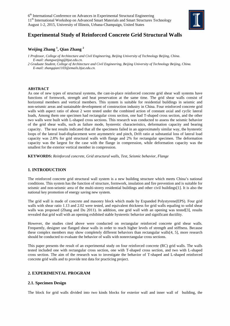
dimension is 395mm×195mm×(200mm+c) and 395mm×195mm×260mm, respectively, where the c is a value for EPS adjustable thickness, which can be adjusted by the different insulation requirements for different regions. Fig. 2.1 shows the dimension of the exterior wall. The blocks are used to act as concrete form at the time of construction and later as sound and thermal insulation at the time of exploitation. When constructing the walls, the formwork of the cast-in-place wall is formed by the hollow masonry wall by aligning hole and staggering the gap. Reinforced mesh sheet are put in the horizontal groove at every layer. After the construction of blocks is finished for every story of building, the reinforced mesh sheet is inserted in vertical cavity. Through the cleaning opening at the bottom of wall, the steel mesh and the lower wall embedded vertical steel banding together. Then, pouring concrete in the cavity, the grid walls are formed by horizontal members and vertical members. For exterior wall, the cross section of vertical member is 200 mm long and 140 mm wide, and the cross section of horizontal member is 115mm height and 140 mm wide, that is, the thickness of concrete wall is 140mm. For inner wall, the cross section of vertical member is 200 mm long and 120 mm wide, and the cross section of horizontal member is 115mm height and 120 mm wide, that is, the thickness of concrete wall is 120mm. The distance between the centerline of vertical members and the centerline of horizontal members are both 400mm for outer wall and inner wall.
(a)Block dimension (b)Exterior wall block
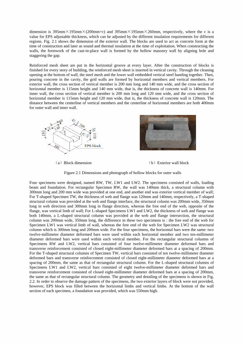
Figure 2.1 Dimensions and photograph of hollow blocks for outer walls Four specimens were designed, named RW, TW, LW1 and LW2. The specimens consisted of walls, loading beam and foundation. For rectangular Specimen RW, the wall was 140mm thick, a structural column with 300mm long and 200 mm wide was provided at one end, and another end was exterior vertical member of wall; For T-shaped Specimen TW, the thickness of web and flange was 120mm and 140mm, respectively, a T-shaped structural column was provided at the web and flange interface, the structural column was 200mm wide, 350mm long in web direction and 300mm long in flange direction, whereas the free end of the web, opposite of the flange, was vertical limb of wall; For L-shaped Specimens LW1 and LW2, the thickness of web and flange was both 140mm, a L-shaped structural column was provided at the web and flange intersection, the structural column was 200mm wide, 350mm long, the difference in these two specimens is : the free end of the web for Specimen LW1 was vertical limb of wall, whereas the free end of the web for Specimen LW2 was structural column which is 300mm long and 200mm wide. For the four specimens, the horizontal bars were the same: two twelve-millimeter diameter deformed bars were used within each horizontal member and two ten-millimeter diameter deformed bars were used within each vertical member. For the rectangular structural columns of Specimens RW and LW2, vertical bars consisted of four twelve-millimeter diameter deformed bars and transverse reinforcement consisted of closed eight-millimeter diameter deformed bars at a spacing of 200mm. For the T-shaped structural columns of Specimen TW, vertical bars consisted of ten twelve-millimeter diameter deformed bars and transverse reinforcement consisted of closed eight-millimeter diameter deformed bars at a spacing of 200mm, the same as that of rectangular structural column. For the L-shaped structural columns of Specimens LW1 and LW2, vertical bars consisted of eight twelve-millimeter diameter deformed bars and transverse reinforcement consisted of closed eight-millimeter diameter deformed bars at a spacing of 200mm, the same as that of rectangular structural column. The geometry and detailing of the specimens is shown in Fig. 2.2. In order to observe the damage pattern of the specimens, the two exterior layers of block were not provided, however, EPS block was filled between the horizontal limbs and vertical limbs. At the bottom of the wall section of each specimen, a foundation was provided, which was 550mm high.
(a)Specimen RW (b)Specimen TW (c)Specimen LW1 (d)Specimen LW2
Figure 2.2 Geometry and reinforcing details of wall specimens[dimensions in mm] Concrete strength was determined on the day each specimen was tested by averaging the results of three 150mm cubes. The cubic concrete compressive strength is 35.38MPa, Test value of concrete axial compressive strength is 29.64 MPa, which is taken to 0.76 times the cube concrete compressive strength. Three tension tests were conducted to determine properties of each reinforcing bar used in all specimens. Young’s modulus of steel is taken to 2.0×10⁵
MPa.The measured yield strength, ultimate strength and yield strain are listed in Table 2.1.
Table 2.1 Material properties of steel Bar diameter
/mm fy f/MPa u ε/MPa y(×10-6)
8 412.35 641.48 2061.75
10 436.26 669.21 2181.30
12 446.45 630.22 2232.25
2.2. Test Setup First, the vertical load was applied which was kept constant during the test. After that, cyclic lateral displacements were imposed to the walls by a hydraulic actuator mounted horizontally to a reaction wall until failure. Fig.2.3 presents the test set up. The foundation was fixed on the test table. An actuator was used to apply the vertical load at the top of the specimen .The vertical load for RW is 270kN, whereas the vertical load for the other three specimens is 400kN, axial ratio is 0.13 for the four specimens. The actuator for horizontal load push and pull, called positive and negative loading, respectively. Flange was under compression for positive loading and structural column was under compression for negative loading, the distance between horizontal loading point and the base of the wall is 3150mm. The shear ratio of Specimen LW2 is 1.97 and the shear ratio of the other specimens is 2.10. Static cyclic lateral loading was applied incrementally during the tests. The testing procedure was divided in two phases. Force-controlled cycles were first applied before specimen reached nominal yield. Each cycle of this phase was repeated once. Displacement-controlled inelastic displacement cycles of increasing amplitude were subsequently applied to each specimen. Each cycle of this phase was repeated twice. Tests were ended after
350X300X200 structural columns 350X350X200 structural columns
350X350X200 structural columns
350X200
300X200 structural columns

significant loss of lateral-load resistance. Instrumentation was used to measure displacements, loads, and strains at critical locations for each grid wall specimen. Five displacement transducers positioned along the height of the wall, the strains in the reinforcing steel were measured through the use of strain gauges, and the locations are shown as Fig. 2.4. The applied vertical and lateral loads were measured using the actuator load cell.
Load-distributing beam
Reaction wall
Lateral actuatorVertical actuator
Arm-tie
the bay bolt
Reaction slab
(a) LVDTs (b) Strain gauges (a) Test setup
(b) Specimen before test
Figure 2.4 Instrumentation arrangement Figure 2.3 Test set up used in experiments
3. EXPERIMENTAL RESULTS 3.1. Cracking Pattern During the horizontal load is 75kN, vertical cracking appeared at the ends of some horizontal limbs of the web portion for all specimens. At the drift ratio of 0.2%, vertical cracking occurred at the ends of most horizontal members of the web portion for all specimens, and gradually went through the height of the horizontal limbs. For Specimen RW, the initiation of horizontal cracking appeared in boundary vertical limb and boundary structural column at the drift ratio of 0.3%. At 1% drift, diagonal cracks occurred in horizontal limbs at the middle lower part of the specimen and formed corner-to-corner diagonal cracks throughout the horizontal member span. Minor crushing of the concrete at the bottom of boundary vertical limb was observed. During the lateral drift level of 1.7%, the horizontal reinforcement exposed in horizontal members at middle lower part of the specimen. During the first cycle to 2.2% lateral drift, most of the horizontal limbs damaged, crushing of the concrete took place at the bottom of boundary vertical limb and boundary structural column, test was stopped due to buckling of longitudinal reinforcement. For Specimen TW, horizontal cracks occurred in boundary vertical limb and at the bottom of vertical limbs of the flange portion at 0.3% lateral drift. During the lateral drift level of 0.67%, diagonal cracks occurred in most of horizontal members of the web portion, horizontal cracks occurred at the bottom of structural column at the web and flange intersection. During the lateral drift level of 1%, horizontal cracks occurred in most of the vertical limbs of the web portion. During the lateral drift level of 1.3%, diagonal cracks occurred in most horizontal limbs of the web portion. The horizontal reinforcement exposed in horizontal members of the web portion near the flange. During lateral drift level of 2%, crushing of the concrete took place at the bottom of boundary vertical limb of the web portion. During the first cycle to 3.6% lateral drift, almost all the horizontal limbs failed, crushing of the concrete took place at the bottom of exterior vertical limb and at the bottom of structural column at the web and flange intersection, test was ended due to buckling of longitudinal reinforcement. For Specimen LW1, horizontal cracks appeared in boundary vertical limb of the web at 0.3% lateral drift. During the lateral drift level of 0.67%, diagonal cracks occurred in most of horizontal limbs of the web, horizontal cracks occurred in the structural column at the web and flange intersection. Vertical cracks occurred at the ends of horizontal limbs of the web portion. During the lateral drift level of 1.3%, the diagonal cracks had

already reached widths of 4mm in the horizontal limb of the web near structural column. Some horizontal bars exposed in horizontal limb of the web near the flange. During the lateral drift level of 2%, crushing of the concrete took place at the bottom of vertical limb of the web. During the first cycle to 3.6% lateral drift, almost all horizontal members of the web failed, minor crushing of the concrete took place at the bottom of vertical limb of the web and at the bottom of structural column, test was ended. For Specimen LW2, horizontal cracks occurred at bottom of the structural column at the free edge of the web at 0.2% lateral drift, diagonal cracks occurred in horizontal members at the middle lower part of the specimen at 0.3% lateral drift. During the lateral drift level of 0.7%, horizontal cracks occurred at top and bottom of structural column at the intersection of web and flange. During the lateral drift level of 1.3%, the width of diagonal cracks reached to 4mm in the horizontal limb of the web portion and some horizontal bars exposed. During the first cycle to 2.5% lateral drift, minor crushing of the concrete took place at the bottom of structural column at the intersection of web and flange. During the first cycle to 3.8% lateral drift, almost all the horizontal members failed, crushing of the concrete took place at the bottom of structural column of the web edge, buckling of longitudinal reinforcement occurred, test was ended due to buckling of longitudinal reinforcement. Fig.3.1 shows photos of the four specimens after failure. All the specimens failed in an approximately similar way, the dominant flexural behavior was expected: vertical cracks at the ends of horizontal limbs extended over the entire height of the limbs, corner-to-corner diagonal cracks occurred throughout the horizontal members, horizontal cracks occurred in the vertical limbs, crushing of the concrete was observed at the bottom of the boundary vertical limb, buckling of longitudinal reinforcement occurred. Compared to the rectangular specimen, the T shaped and L shaped walls damaged more fully. For the Specimen LW2 with structural column, horizontal members and vertical members of the web damaged more fully. The structural column at the web-flange intersection had minor damage, Good connection performance was observed at the web and the flange intersection.
(a)Specimen RW (b)Specimen TW (c)Specimen LW1 (d)Specimen LW2
Figure 3.1 Specimens after failure 3.2. Lateral Load-Deformation Responses The displacement-horizontal load curve is shown in Fig.3.2, where the displacement is the measured data from the top of the wall, and the distance between the top of wall and the base of the wall is 2950mm. From Fig.3.2, we can see that the curves are asymmetric due to the asymmetry of cross section and reinforcement. The curves exhibited pinching effect, which means there were lots of cracks and the cracks developed fully. When unloaded to zero, Residual displacement was small, meaning that cracks can be closed, the walls have a strong ability to recover; after the peak horizontal load, the horizontal force decreases with the increase of the lateral displacements. No sudden loss of vertical bearing capacity could be observed, the grid walls showed good deformation capacity.

-300
-200
-1000
100
200
300
-80 -60 -40 -20 0 20 40 60 80
Δ /mm
F /kN
-300
-200
-100
0
100
200
300
-140 -100 -60 -20 20 60 100 140
Δ /mm
F /kN
-300
-200
-100
0
100
200
300
-140 -100 -60 -20 20 60 100 140
Δ /mm
F /kN
-300-200-100
0100200300
-140 -100 -60 -20 20 60 100 140
Δ /mm
F /kN
(a)Specimen RW (b)Specimen TW (c)Specimen LW1 (d)Specimen LW2
Figure 3.2 Hysteresis loops of top displacement versus lateral load 3.3. Load Capacity Table 3.1 shows the cracking load Fc , yield load Fy and the peak load F
p.
Test result shows that: the cracking loads are similar for the specimens, for Specimen RW with rectangular cross section, the nominal yield horizontal load and peak horizontal load in the case of structural column in tension increased 24.49% and 21.86% than the vertical limb in tension. For Specimens TW and LW1, the nominal yield horizontal load and peak horizontal load in the case of web in tension increased 13.66% and 11.9%, 17.61% and 25.11%, respectively, than the vertical limb or structural column in tension. For Specimen LW2, the nominal yield horizontal load and peak horizontal load in case for web in tension is similar to those of the vertical limb or structural column in tension. For Specimen TW and LW1, the nominal yield horizontal load and peak horizontal load in case for web in tension are similar, in the case of vertical limb in tension are similar too. For Specimen LW2, the nominal yield horizontal load and peak horizontal load in the case of structural column in tension are larger than those of the vertical limb in tension for Specimens TW and LW1. In general, the lateral load capacity was the largest for the case with the flange in tension, followed by the case with the structural column in tension, whereas lateral load capacity was smallest for the case with vertical limb in tension.
Table 3.1 Lateral load at different levels Specimen
ID Fc F/kN y F/kN p/kN
positive negative positive negative positive negative RW 74.54 74.87 117.30 94.22 169.63 139.20 TW 74.06 75.70 152.71 134.36 175.65 156.97 LW1 75.02 75.20 152.39 129.57 194.74 155.66 LW2 75.54 79.84 162.13 169.63 215.96 214.27
3.4. Deformation Capacity Table 3.2 shows the top horizontal drift at different levels. The ultimate drift is the value corresponding the 85% of the peak loading, if the peak loading doesn’t decrease to the 85%, the ultimate drift is the value when the test stop.
Table 3.2 Drift ratio at different levels (%) Specimen
ID Cracking θ Nominal field θc Peak θy Ultimate θp u
positive negative positive negative positive negative positive negative RW 0.097 0.14 0.24 0.44 0.85 1.18 1.22 2.22 TW 0.095 0.14 0.44 0.49 0.65 0.85 1.22 3.85
LW1 0.074 0.13 0.32 0.32 0.96 0.95 1.61 3.58 LW2 0.091 0.08 0.33 0.36 0.96 0.65 2.38 3.85
Test results show that the drift ratio for cracking in positive direction are less than 0.1 %( 1/1000), the nominal yield drift ratio are 0.24%~0.5%, ultimate drift ratio are larger than 0.83 %( 1/120) which required by china code for structural walls under severe earthquake. Test results also show that the ultimate drift ratio or deformation capacity is related to the structure of compressive end. When the compressive end is vertical limb, the ultimate drift ratio is 1.61% for LW1 in the positive loading direction or 1.22% for RW and TW in the

positive loading direction. When the compressive end is structural column, the ultimate drift ratio is 2.38% for LW2 in the positive loading direction or 2.22% for RW in the negative loading direction, which is more than 1.38 times the drift ratio for the case with compressive vertical limb. When compressive end is the flange, the ultimate drift ratio is 3.58% in the negative loading direction for LW1 or 3.85% for TW and LW2 in the negative loading direction, which is more than 2.2 times the drift ratio with compressive vertical limb. In general, the elastoplasticity deformation capacity is largest for the case with flange in compression, followed the case with structural column in compression, the deformation capacity is smallest for the case with vertical limb in compression. 4. CONCLUSIONS Based on the experimental research on grid walls with different types of cross sections, the following findings are summarized as follows: (1) All the specimens failed in an approximately similar way, vertical cracks concentrated at both ends of
horizontal limbs and extended over the height of the horizontal limbs, corner-to-corner diagonal cracks occurred throughout the horizontal limbs, horizontal cracks formed in the vertical limbs, the buckling of edge boundary bars and crushing of the concrete took place at the bottom of the free edge of the web and at the bottom of the web and the flange intersection.
(2) Lateral load-displacement hysteretic loops were asymmetric and exhibited a noticeable pinching effect.
After achieving the maximum load bearing capacity, with the increase of displacement, lateral load decreased slowly.
(3) The lateral load capacity was the largest for the case with the flange in tension, followed the case with
structural column in tension, whereas lateral load capacity was smallest for the case with vertical limb in tension.
(4) The ultimate drift ratios are greater than 1/120. The deformation capacity was the largest for the case with
the flange in compression, whereas deformation capacity was the smallest for the case with vertical limb in compression.
AKCNOWLEDGEMENT The work presented in this paper was supported by funds from the Key Projects in the National Science & Technology Pillar Program during the Twelfth Five-year Plan Period under Grant No 2012BAJ03B04 and the Beijing Municipal University Teacher Training Project under Grant No 67145301400. These financial supports are gratefully acknowledged. The authors would like to thank Prof. Wallace, the director at UCLA, for his opinion on the project. REFERENCES 1. Feng, B.C, Xu, C. H, and Mu, S. Q. (2003). Heat Preservation and Insulation Hollow Block Cast-in-Site
Concrete Bearing Wall System.Walling Material Innovation and Energy Conservation of Buildings. 8: 43-45.( in Chinese)
2. Zhang,W. J, Du, Y. N, and Kang, H .Z. (2011). Experimental Study on Seismic Behavior of Large Grid Size RC Shear Walls. Journal of Building Structures. 32: 5,116-124. (In Chinese).
3. Zhang,W. J, Wang, J. J, and Zhang, Q. (2013). Experimental study on seismic behavior of grid structural walls with openings. Industrial Construction.1480-1484. (In Chinese).
4. Wallace, J. W., and Thomsen, J. H. (2004). Displacement-Based Design of Slender Reinforced Concrete Structural Walls-Experimental Verification. Journal of Structural Engineering. 130: 4,618-630.
5. Karamlou, A., and Kabir, M. Z. (2012). Experimental Study of L-shaped Slender R-ICF shear walls under cyclic lateral loading. Engineering Structures. 36:134-146.