experimental study of the effects of the cathode position ...bustlab.boun.edu.tr/assets/b37 - 2016...
TRANSCRIPT

Experimental Study of the Effects of the Cathode
Position and the Electrical Circuit Configuration on
the Operation of HK40 Hall Thruster and BUSTLab
Hollow Cathode
Nazli Turan∗, Ugur Kokal†, Murat Celik‡
Bogazici University, Istanbul, 34342, Turkey
Huseyin Kurt§
Istanbul Medeniyet University, Istanbul, 34700, Turkey
HK40 Hall thruster, designed and developed at the Bogazici University Space Tech-nologies Laboratory (BUSTLab), is an SPT type Hall thruster with a 40 mm dischargechannel. HK40 was initially designed to operate with SmCo permanent magnets. To op-timize the magnetic field topology, the permanent magnets were replaced with iron-coreelectromagnets. The thruster is operated with different magnetic coil currents to observethe changes in discharge characteristics. Magnetic field topology of the thruster is exam-ined to determine the proper location of a LaB6 hollow cathode, which is also designed andbuilt at BUSTLab. External magnetic field topology of a Hall thruster has an importantcharacteristic called magnetic field separatrix defining the boundary between closed mag-netic surfaces and open magnetic field lines. To investigate the effects of the separatrixsurfaces, the location of the cathode is changed in-situ with respect to the Hall thrusterwith a 2-D translational stage in two different grounding configurations, one connectingthe vacuum chamber to the same ground with the power supplies, and the other with thepower supplies connected to a common floating ground. We show that the influence ofthe external magnetic field strength on the thruster efficiency can be predicted from theelectron current coming from the cathode emitter surface. We also show that the cathodeto ground voltage provides a way to estimate the efficiency with respect to the cathodeplacement. The mechanisms and the efficiency values of two setups are compared to explainthe ground and the space operations.
I. Introduction
Electric propulsion systems are increasingly being employed in satellites and spacecraft as alternativesto chemical thrusters due to their lower propellant consumption and resulting cost savings.1 Hall-effectthrusters (HETs) are a class of electric propulsion devices. In Hall effect thrusters, electric and magneticfields are used to create a plasma and to expel the ions at high velocities to produce thrust. Even thoughthe imposed magnetic field affects both the electrons and the ions, the ions move mostly unaffected by themagnetic field due to their higher mass, and are accelerated by the applied electric field. There are threetypes of electron motion in Hall effect thrusters: (i) electron motion along the local magnetic field linesinto the channel, (ii) closed drift, E × B, motion to distribute electrons around the channel, (iii) cross-field(transverse) electron motion towards the anode.2
The paths of electrons are illustrated in Figure 1. The E×B drift velocity is E/B in magnitude and occursalong the channel circumference contributing to the Hall current. The maximum magnetic field strength is
∗Graduate Student, Department of Mechanical Engineering, Bogazici University.†Graduate Student, Department of Mechanical Engineering, Bogazici University.‡Associate Professor, Department of Mechanical Engineering, Bogazici University.§Associate Professor, Department of Engineering Physics, Istanbul Medeniyet University
1 of 14
American Institute of Aeronautics and Astronautics
Dow
nloa
ded
by P
UR
DU
E U
NIV
ER
SIT
Y o
n Ju
ly 2
9, 2
016
| http
://ar
c.ai
aa.o
rg |
DO
I: 1
0.25
14/6
.201
6-48
34
52nd AIAA/SAE/ASEE Joint Propulsion Conference
July 25-27, 2016, Salt Lake City, UT
AIAA 2016-4834
Copyright © 2016 by Nazli Turan, Ugur Kokal, Murat Celik, Huseyin Kurt. Published by the American Institute of Aeronautics and Astronautics, Inc., with permission.
Propulsion and Energy Forum
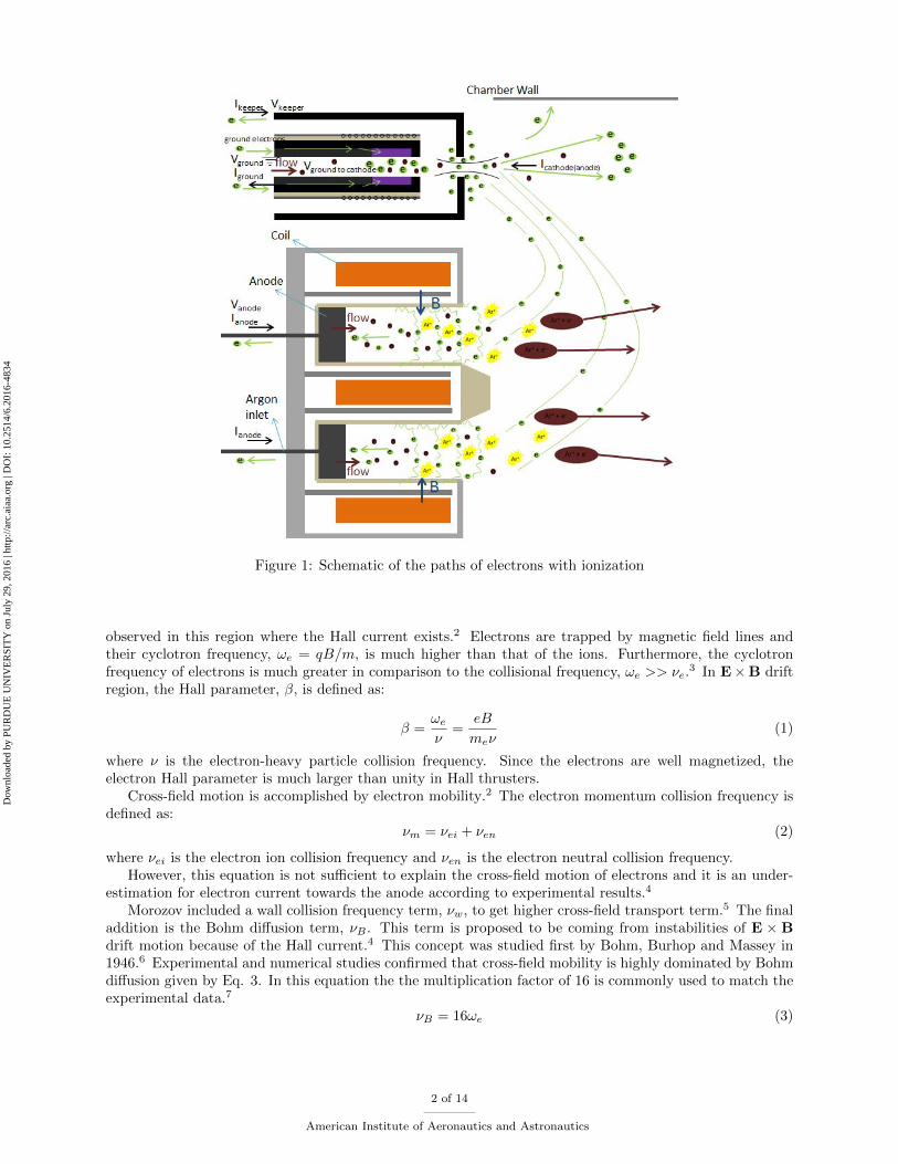
Figure 1: Schematic of the paths of electrons with ionization
observed in this region where the Hall current exists.2 Electrons are trapped by magnetic field lines andtheir cyclotron frequency, ωe = qB/m, is much higher than that of the ions. Furthermore, the cyclotronfrequency of electrons is much greater in comparison to the collisional frequency, ωe >> νe.
3 In E×B driftregion, the Hall parameter, β, is defined as:
β =ωe
ν=
eB
meν(1)
where ν is the electron-heavy particle collision frequency. Since the electrons are well magnetized, theelectron Hall parameter is much larger than unity in Hall thrusters.
Cross-field motion is accomplished by electron mobility.2 The electron momentum collision frequency isdefined as:
νm = νei + νen (2)
where νei is the electron ion collision frequency and νen is the electron neutral collision frequency.However, this equation is not sufficient to explain the cross-field motion of electrons and it is an under-
estimation for electron current towards the anode according to experimental results.4
Morozov included a wall collision frequency term, νw, to get higher cross-field transport term.5 The finaladdition is the Bohm diffusion term, νB . This term is proposed to be coming from instabilities of E × Bdrift motion because of the Hall current.4 This concept was studied first by Bohm, Burhop and Massey in1946.6 Experimental and numerical studies confirmed that cross-field mobility is highly dominated by Bohmdiffusion given by Eq. 3. In this equation the the multiplication factor of 16 is commonly used to match theexperimental data.7
νB = 16ωe (3)
2 of 14
American Institute of Aeronautics and Astronautics
Dow
nloa
ded
by P
UR
DU
E U
NIV
ER
SIT
Y o
n Ju
ly 2
9, 2
016
| http
://ar
c.ai
aa.o
rg |
DO
I: 1
0.25
14/6
.201
6-48
34

Thus, the total collision frequency becomes:
νm = νei + νen + νw + νB (4)
Hall parameter, β, and electric conductivity, σ, provide a way to explain the relation between electricfield and magnetic field in Hall effect thrusters.
The current density is obtained from the relation:
J = σE (5)
Conductivity has components in all directions which are all proportional to 1/(1 + β2).8 The currentdensity in the longitudinal direction has relationship:
Jz ∼ E
1 + β2(6)
If the magnetic field strength is high in a region, then the Hall parameter is large, and the current densityis low in this region. According to Eq. 5, conductivity and current density are affected by the electric fieldin a similar manner. Therefore, σz would have a proportionality relationship:
σz ∼ 1
β2(7)
According to Eq.7, in the strongest magnetic field region, electron current flow is restricted becauseelectrons are trapped in magnetic field lines. On the other hand, for large ωe the Hall parameter is large.Electrons follow the magnetic field lines by experiencing cyclotron motion. In the acceleration region,electrical conductivity is low but electric field reaches a maximum value. Electron temperature and plasmapotential gradients along magnetic field lines are low. Therefore, the lines are considered as equipotential.9
As a result, electrons ionize the neutrals in the channel and ions could be attracted to the thruster exit dueto low potential at thruster exit.
For the operation of the thruster in optimum conditions, the topology of the magnetic field is an importantdesign parameter. In this study, the magnetic field characteristics of HK40 Hall effect thruster is assessed byconsidering the location of the electron source which is the LaB6 insert inside the hollow cathode and theseparatrix surfaces formed by the external magnetic field of the thruster. Thruster efficiency mechanismsare investigated by measuring ground current for the grounded setup (section IV.A), and cathode to groundvoltage for the floating setup (section IV.B). The vacuum tank effects and the space operation are discussed.
Figure 2: HK40 Hall effect thruster with BUSTlab LaB6 hollow cathode
3 of 14
American Institute of Aeronautics and Astronautics
Dow
nloa
ded
by P
UR
DU
E U
NIV
ER
SIT
Y o
n Ju
ly 2
9, 2
016
| http
://ar
c.ai
aa.o
rg |
DO
I: 1
0.25
14/6
.201
6-48
34

II. HK40 Hall Effect Thruster
HK40, designed and built at BUSTLab, is an SPT type Hall thruster with a dielectric channel outerdiameter of 40 mm. In its original design, the thruster had 1/2 inch diameter and 1 inch long cylindricalSamarium-Cobalt permanent magnets; four outer and one inner. Recently, these permanent magnets werereplaced with iron-core electromagnets of the same physical size. A rendering of the 3D technical drawingand a side view picture of HK40 with BUSTLab LaB6 hollow cathode in operation are shown in Figure 2.
External magnetic field topology of a Hall effect thruster has an important characteristic called magneticfield separatrix that signifies the surface which forms the boundary between closed magnetic surfaces andopen field lines. Inside the separatrix, magnetic field lines capture electrons near the discharge region andalong the beam while outside the separatrix, the magnetic field lines orient electrons away from the beam.13
In this study, location of the cathode with respect to the separatrix surfaces are investigated in-situ bymoving the cathode with a 2-D translation stage.
III. BUSTLab Hollow Cathode
Electron sources, such as hollow cathodes, are essential parts of the electric propulsion systems ionizationand neutralization processes. For Hall thrusters, the cathode electrons ionize the neutral gas in the chamberand neutralize the ion beam exiting the thruster.
Figure 3: LaB6 hollow cathode test setup for current extraction with a virtual anode
The prototype hollow cathode, designed and built at BUSTLab, has a 6 mm outer diameter 48 mm longgraphite cathode tube. It utilizes a 2 mm ID, 4 mm OD LaB6 tube of 10 mm length as the thermionicemission material. The insert region of the cathode is heated using a heater assembly that utilizes 0.25 mmdiameter tantalum wire that is wrapped around a high temperature machinable ceramic (shapal) tube withexternal helical grooves. A specially designed coaxial graphite part is used providing current to the heatingwire, and alumina parts are used for electrical and thermal insulation of the heater wire.
BUSTLab hollow cathode characteristics were determined by conducting measurements using a virtualanode. The setup for the cathode tests with a virtual anode is shown in Figure 3. By operating the cathodein this setup, virtual anode current and voltage values are obtained for different mass flow rates and keepercurrent values. According to these tests, the suitable cathode mass flow rate is determined to be 2.2 sccmfor Argon propellant.
The source of the electrons that leave the cathode, thus providing the cathode current, is the LaB6 insertlocated inside the cathode tube. As seen in Figure 4, the insert is at ground potential. As LaB6 insertemits electrons, it would start extracting electrons from ground. In the experiments, the electrons extractedfrom the ground are measured and considered as the cathode current. The cathode current is measuredwith a multimeter connected to the heater return wire. The cathode is isolated from the ground inside the
4 of 14
American Institute of Aeronautics and Astronautics
Dow
nloa
ded
by P
UR
DU
E U
NIV
ER
SIT
Y o
n Ju
ly 2
9, 2
016
| http
://ar
c.ai
aa.o
rg |
DO
I: 1
0.25
14/6
.201
6-48
34

vacuum tank so that it attracts all the electrons from the ground outside the tank to be measured with themultimeter.
Figure 4: Electron extraction from LaB6 emitter surface
IV. Electrical Circuits for the Thruster-Cathode System
In order to illustrate the electrical circuits of the thruster-cathode system for two different setups, repre-sentative schematics are created as shown in Figures 5 and 6.
A. Grounded setup
In the first setup the power sources, which provide the anode and keeper voltages, are grounded to thevacuum chamber (Vg). Cathode is also grounded through a multimeter, which measures the cathode toground current (Ig).
Figure 5: Electrical circuit for the thruster-cathode system for the grounded setup
The anode and the cathode can be characterized as a closed circuit where Rb, Rc, and Rk are the re-sistances between plasma and anode, plasma and cathode (LaB6 insert), and keeper and cathode (LaB6
insert), respectively. Rk is the resistance between the cathode insert and the keeper. Rb is created by themagnetic field topology in the discharge channel and is proportional to the square of the Hall parameteras in the Eq.7. Therefore Rb increases by the increased strength of the magnetic field resulting in moreionization in the channel. The magnitude of the radial component of the magnetic field should not be toohigh to prevent the electron current towards the anode. Rc depends on the placement of the cathode as wellas the external magnetic field topology of the thruster. Rc is the main concern of this study. In the currentstudy, the movement of the hollow cathode using a 2-D translation stage affects the value of Rc.
Since the ground tests are conducted inside the vacuum chamber, Rtb and Rtc terms are added to thesystem, which represents the resistance between the thruster plume and vacuum chamber wall, and theresistance between the cathode and the vacuum chamber wall, respectively.
5 of 14
American Institute of Aeronautics and Astronautics
Dow
nloa
ded
by P
UR
DU
E U
NIV
ER
SIT
Y o
n Ju
ly 2
9, 2
016
| http
://ar
c.ai
aa.o
rg |
DO
I: 1
0.25
14/6
.201
6-48
34

B. Floating setup
In the floating setup, the negative ends of the power sources of the anode and keeper, and the return wire ofthe heater, which is connected to the insert material, are all connected at a floating common point (calledthe common ground). Common ground and the ground of the vacuum chamber are connected througha multimeter, which measures the voltage (Vcg) between the floating common ground voltage and groundvoltage. This setup represents the electrical circuit of a thruster on a spacecraft.
Figure 6: Electrical circuit for the thruster-cathode system for floating setup
In this setup, cathode current (Ig) is equal to the sum of the keeper current (Ik) and discharge current(Id). In this configuration, total neutralization of the ion beam leaving the thruster is achieved.
Figure 7: Hall thruster voltage schematic
The potential difference between the anode and the cathode generates the discharge voltage (Vd) as canbe seen in Figure 7. In the grounded setup, cathode voltage (Vcg) is zero, therefore anode voltage (Va) isequal to the discharge voltage and read from the power source. In the floating setup, cathode voltage (Vcg)is not zero, therefore the potential difference that is generated by the power source is the discharge voltagewhich is equal to the difference between the anode voltage (Va) and cathode voltage (Vcg).
Plasma potential (Vp) is measured in the thruster plume and defined as the voltage at the thruster exitwhere the ion acceleration is completed. The accelerated ions fall through a potential (Vb), that correspondsto the potential difference between the anode voltage and the plasma potential. Cathode coupling voltage(Vc) is the voltage between the plume plasma potential and the cathode voltage.
6 of 14
American Institute of Aeronautics and Astronautics
Dow
nloa
ded
by P
UR
DU
E U
NIV
ER
SIT
Y o
n Ju
ly 2
9, 2
016
| http
://ar
c.ai
aa.o
rg |
DO
I: 1
0.25
14/6
.201
6-48
34

V. Theoretical Estimation of Thruster Efficiency
A. Calculating efficiency from the ground current
The ions are accelerated from the location of their creation inside the discharge chamber towards the down-stream plume region. The plume plasma potential depends on the electron current supplied from the cathode,magnetic field topology, the placement of the cathode and the discharge characteristics. Even though theions are created at a region that has slightly less potential than the anode potential, it can be estimatedthat the beam power is:
Pb = Ib(Va − Vp) (8)
Beam current (Ib) is calculated from the difference between the discharge current (Id) and the electroncurrent emitted from the cathode (Iec) as in Eq.9.4 The discharge current is formed by incoming electronsfrom the cathode and by the ionization of the neutrals:
Id = Iec + Ib (9)
where Iec, the cathode electrons, is measured from the ground current. There are equal number of electronsand ions in the plasma discharge after ionization as seen from Eq. 10:
Ib = Iei (10)
where Iei is the electrons created after ionization. The created ions are expelled towards the exit whileelectrons flow towards the anode as depicted in Figure 1. The thrust is calculated as:
T =Ibmi
e
√2eVbmi
(11)
and the efficiency becomes:
ηT =1
2
T 2
mtPt(12)
where mt is the sum of mass flow rates to the anode and the cathode, and Pt is the total power whichincludes the power to anode, keeper and magnetic coils.10
With an increase in magnetic field strength, anode voltage becomes higher for a constant discharge(anode) current. With constant discharge current, ground current (current from ground to the cathode)decreases, meaning that the electron current extracted from the cathode decreases as will be explained inSection VII.
B. Calculating efficiency from cathode to ground voltage
For this setup, the discharge current is equal to the cathode current.
Id = Icathode (13)
also the cathode electrons ionize the neutrals Iec and neutralize the beam ions Ieb:
Icathode = Iec + Ieb (14)
The voltage that accelerates the ions is calculated as the difference between the applied anode voltageand the cathode coupling voltage as in Figure 7.
Vb = Vd − Vc (15)
Thrust is defined as:T = mvavg (16)
where m is the ionized propellant mass flow rate and vavg is the average axial exit velocity of ions given by:
vavg = a
√2e(Vd − Vc)
mi(17)
7 of 14
American Institute of Aeronautics and Astronautics
Dow
nloa
ded
by P
UR
DU
E U
NIV
ER
SIT
Y o
n Ju
ly 2
9, 2
016
| http
://ar
c.ai
aa.o
rg |
DO
I: 1
0.25
14/6
.201
6-48
34
wheremi represents ion mass, a is a constant coming from the divergence losses calculated with the divergencehalf angle, cos(θ), and e is the electron charge.11 Argon ions are assumed to be only singly ionized.
Thruster efficiency is calculated as in Eq.12 by calculating the mass flow rate of the ionized gas from thebeam current:
ηT =a2em(Vd − Vc)
mi(IdVd + Pmagnet + Pcathode)(18)
where Id is the current supplied to the anode.In the conducted experiments, by measuring the ground current the beam current is calculated from the
cathode current. Regarding the beam current, the ionization ratio of the propellant is calculated to be inthe range of 75 − 80% when an Argon flow rate of 18 sccm is supplied to the anode. This ratio is used forthe calculation of thrust using Eq.16. The loss caused by the beam divergence are estimated from the visualobservation of the thruster operation. The divergence angle was taken to be 40 degrees. The efficiency valuecalculated with this angle and named as corrected efficiency.
VI. Experimental Setup for the Cathode Placement Tests
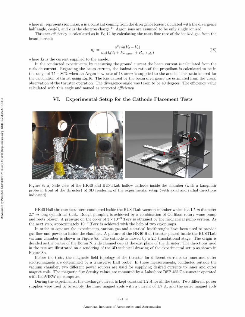
Figure 8: a) Side view of the HK40 and BUSTLab hollow cathode inside the chamber (with a Langmuirprobe in front of the thruster) b) 3D rendering of the experimental setup (with axial and radial directionsindicated)
HK40 Hall thruster tests were conducted inside the BUSTLab vacuum chamber which is a 1.5 m diameter2.7 m long cylindrical tank. Rough pumping is achieved by a combination of Oerlikon rotary wane pumpand roots blower. A pressure on the order of 3× 10⁻³ Torr is obtained by the mechanical pump system. Asthe next step, approximately 10−7 Torr is achieved with the help of two cryopumps.
In order to conduct the experiments, various gas and electrical feedthroughs have been used to providegas flow and power to inside the chamber. A picture of the HK40 Hall thruster placed inside the BUSTLabvacuum chamber is shown in Figure 8a. The cathode is moved by a 2D translational stage. The origin isdecided as the center of the Boron Nitride channel cup at the exit plane of the thruster. The directions usedin the test are illustrated on a rendering of the 3D technical drawing of the experimental setup as shown inFigure 8b.
Before the tests, the magnetic field topology of the thruster for different currents to inner and outerelectromagnets are determined by a transverse Hall probe. In these measurements, conducted outside thevacuum chamber, two different power sources are used for supplying desired currents to inner and outermagnet coils. The magnetic flux density values are measured by a Lakeshore DSP 455 Gaussmeter operatedwith LabVIEW on computer.
During the experiments, the discharge current is kept constant 1.2 A for all the tests. Two different powersupplies were used to to supply the inner magnet coils with a current of 1.7 A, and the outer magnet coils
8 of 14
American Institute of Aeronautics and Astronautics
Dow
nloa
ded
by P
UR
DU
E U
NIV
ER
SIT
Y o
n Ju
ly 2
9, 2
016
| http
://ar
c.ai
aa.o
rg |
DO
I: 1
0.25
14/6
.201
6-48
34

Figure 9: Test points in 2D plane for the grounded setup (inner coil = 1.7 A, outer coils = 2 A)
Figure 10: Test points in 2D plane for the floating setup (inner coil = 1 A, outer coils = 1.2 A)
with a current of 2.0 A. These magnet current values are determined as the optimum operation currents forthe grounded tests . The Hall probe results are compared with COMSOL modeling of the thruster magneticfield topology and the model is optimized after the measurements. According to the magnetic topologymodel, for the stated inner and outer magnet current values the maximum magnetic field strength in thechannel is 360 G. For this setup, the efficiency is predicted using Eq.12 regarding the ground current. Thepower supplies are grounded and the current extracted from the ground is measured by serially connecting
9 of 14
American Institute of Aeronautics and Astronautics
Dow
nloa
ded
by P
UR
DU
E U
NIV
ER
SIT
Y o
n Ju
ly 2
9, 2
016
| http
://ar
c.ai
aa.o
rg |
DO
I: 1
0.25
14/6
.201
6-48
34

a multimeter between the heater return wire and the ground. The locations at which data were taken areillustrated in Figure 9.
For the tests conducted with the floating setup to measure cathode to ground voltage, the optimummagnetic field was obtained by supplying 1 A to the inner coil and 1.2 A to the outer coils. For thesecurrent values the maximum magnetic field strength was determined to be 220 G. HK40 and hollow cathodewere operated in the vacuum chamber. The discharge characteristics and cathode-to-ground voltage weremeasured in-situ while changing the relative location of the cathode with respect to the HK40. Efficiency iscalculated using Eq.18 by measuring the cathode to ground voltage. The locations at which data were takenfor the floating setup are illustrated in Figure 10. During these tests, all the electronic parts are connectedto a common ground as described in section IV.B.
The plume plasma characteristics were investigated by measuring electron number density, electron tem-perature, and plasma potential using a single Langmuir probe. The probe used in these measurementshave a 1 mm diameter molybdenum rod inside a single hole alumina tube of 3.2 mm OD. A Keithley 2410sourcemeter is used for biasing the probe electrode and collecting current.
To observe the separatrix surface, a finite element model of the HK40 Hall effect thruster was constructedover a 2D domain which was obtained from the cross-section cut of the 3D CAD drawing of the thruster.The numerical simulations were done using COMSOL finite element software. The cross-section planepasses through the center of the thruster and the centers of electromagnets for the latest design. The coloredcontours show the z-component of the vector potential with values very close to zero, which stands for theseparatrix surface.
VII. Results and Discussions
Figure 11: a) Test points with respect to separatrix surfaces (inner coil = 1.7 A, outer coils = 2 A) b)Changes in electron current and plasma potential at specified points (inner coil = 1.7 A, outer coils = 2 A)
The tests were conducted with two different setups as mentioned earlier. The data points were selectedconsidering the separatrix surfaces. For the grounded setup, as the cathode is moved away from the thrusterradially, the cathode current decreases sharply after the separatrix. The reason for that could be the increasedresistance (Rc) created by the magnetic field lines in front of the cathode. When the discharge current isconstant as 1.2 A, the ionization in the discharge chamber should be higher if the cathode is outside theseparatrix to satisfy the condition in Eq.9. At point j, plasma potential is measured by the Langmuir probeto be 43 V with less electron supplied from the cathode, while the potential is 23 V at point h in Figure 11.However, the anode voltage increases as the cathode is moved from point h to point j due to the resistancecaused by the presence of magnetic field. The increase in the anode voltage is larger than the increase in
10 of 14
American Institute of Aeronautics and Astronautics
Dow
nloa
ded
by P
UR
DU
E U
NIV
ER
SIT
Y o
n Ju
ly 2
9, 2
016
| http
://ar
c.ai
aa.o
rg |
DO
I: 1
0.25
14/6
.201
6-48
34
the plasma potential. Therefore, the beam voltage is higher at point j relative to point h. The other pointsinside the separatrix have close values for the cathode current and the plasma potential.
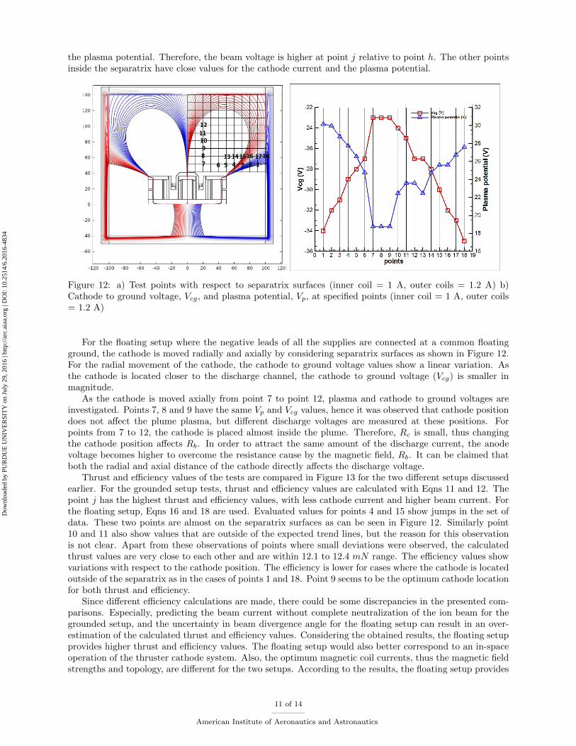
Figure 12: a) Test points with respect to separatrix surfaces (inner coil = 1 A, outer coils = 1.2 A) b)Cathode to ground voltage, Vcg, and plasma potential, Vp, at specified points (inner coil = 1 A, outer coils= 1.2 A)
For the floating setup where the negative leads of all the supplies are connected at a common floatingground, the cathode is moved radially and axially by considering separatrix surfaces as shown in Figure 12.For the radial movement of the cathode, the cathode to ground voltage values show a linear variation. Asthe cathode is located closer to the discharge channel, the cathode to ground voltage (Vcg) is smaller inmagnitude.
As the cathode is moved axially from point 7 to point 12, plasma and cathode to ground voltages areinvestigated. Points 7, 8 and 9 have the same Vp and Vcg values, hence it was observed that cathode positiondoes not affect the plume plasma, but different discharge voltages are measured at these positions. Forpoints from 7 to 12, the cathode is placed almost inside the plume. Therefore, Rc is small, thus changingthe cathode position affects Rb. In order to attract the same amount of the discharge current, the anodevoltage becomes higher to overcome the resistance cause by the magnetic field, Rb. It can be claimed thatboth the radial and axial distance of the cathode directly affects the discharge voltage.
Thrust and efficiency values of the tests are compared in Figure 13 for the two different setups discussedearlier. For the grounded setup tests, thrust and efficiency values are calculated with Eqns 11 and 12. Thepoint j has the highest thrust and efficiency values, with less cathode current and higher beam current. Forthe floating setup, Eqns 16 and 18 are used. Evaluated values for points 4 and 15 show jumps in the set ofdata. These two points are almost on the separatrix surfaces as can be seen in Figure 12. Similarly point10 and 11 also show values that are outside of the expected trend lines, but the reason for this observationis not clear. Apart from these observations of points where small deviations were observed, the calculatedthrust values are very close to each other and are within 12.1 to 12.4 mN range. The efficiency values showvariations with respect to the cathode position. The efficiency is lower for cases where the cathode is locatedoutside of the separatrix as in the cases of points 1 and 18. Point 9 seems to be the optimum cathode locationfor both thrust and efficiency.
Since different efficiency calculations are made, there could be some discrepancies in the presented com-parisons. Especially, predicting the beam current without complete neutralization of the ion beam for thegrounded setup, and the uncertainty in beam divergence angle for the floating setup can result in an over-estimation of the calculated thrust and efficiency values. Considering the obtained results, the floating setupprovides higher thrust and efficiency values. The floating setup would also better correspond to an in-spaceoperation of the thruster cathode system. Also, the optimum magnetic coil currents, thus the magnetic fieldstrengths and topology, are different for the two setups. According to the results, the floating setup provides
11 of 14
American Institute of Aeronautics and Astronautics
Dow
nloa
ded
by P
UR
DU
E U
NIV
ER
SIT
Y o
n Ju
ly 2
9, 2
016
| http
://ar
c.ai
aa.o
rg |
DO
I: 1
0.25
14/6
.201
6-48
34
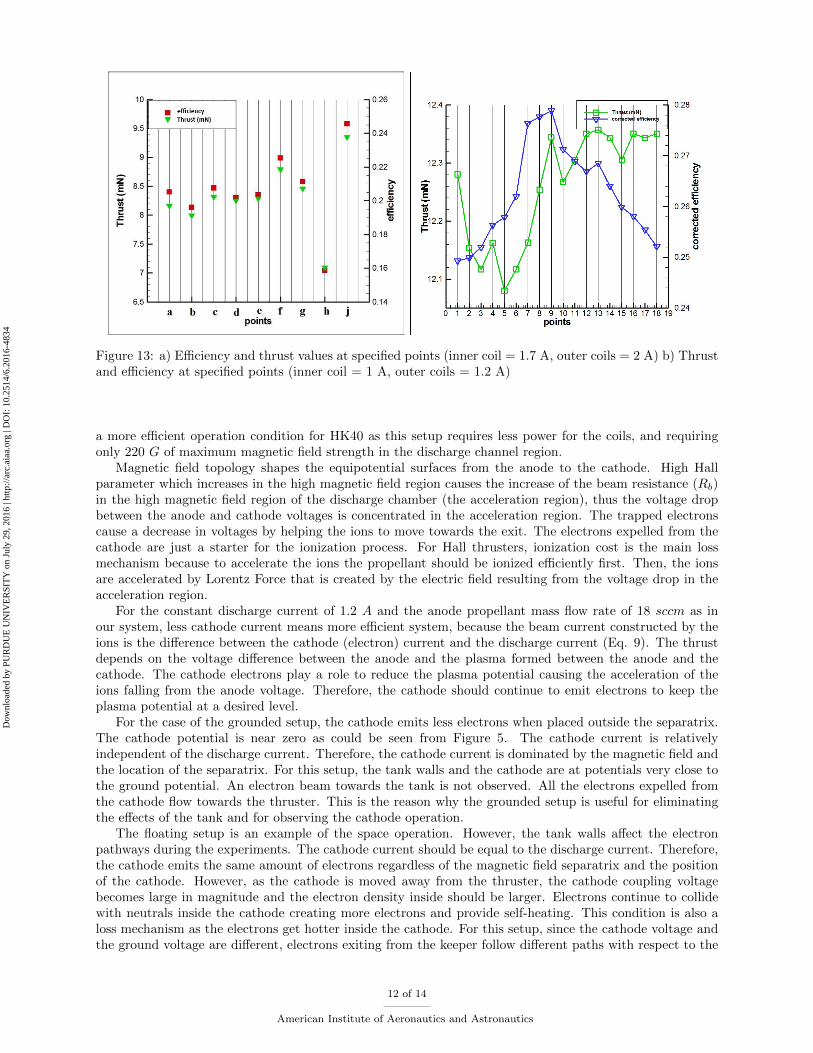
Figure 13: a) Efficiency and thrust values at specified points (inner coil = 1.7 A, outer coils = 2 A) b) Thrustand efficiency at specified points (inner coil = 1 A, outer coils = 1.2 A)
a more efficient operation condition for HK40 as this setup requires less power for the coils, and requiringonly 220 G of maximum magnetic field strength in the discharge channel region.
Magnetic field topology shapes the equipotential surfaces from the anode to the cathode. High Hallparameter which increases in the high magnetic field region causes the increase of the beam resistance (Rb)in the high magnetic field region of the discharge chamber (the acceleration region), thus the voltage dropbetween the anode and cathode voltages is concentrated in the acceleration region. The trapped electronscause a decrease in voltages by helping the ions to move towards the exit. The electrons expelled from thecathode are just a starter for the ionization process. For Hall thrusters, ionization cost is the main lossmechanism because to accelerate the ions the propellant should be ionized efficiently first. Then, the ionsare accelerated by Lorentz Force that is created by the electric field resulting from the voltage drop in theacceleration region.
For the constant discharge current of 1.2 A and the anode propellant mass flow rate of 18 sccm as inour system, less cathode current means more efficient system, because the beam current constructed by theions is the difference between the cathode (electron) current and the discharge current (Eq. 9). The thrustdepends on the voltage difference between the anode and the plasma formed between the anode and thecathode. The cathode electrons play a role to reduce the plasma potential causing the acceleration of theions falling from the anode voltage. Therefore, the cathode should continue to emit electrons to keep theplasma potential at a desired level.
For the case of the grounded setup, the cathode emits less electrons when placed outside the separatrix.The cathode potential is near zero as could be seen from Figure 5. The cathode current is relativelyindependent of the discharge current. Therefore, the cathode current is dominated by the magnetic field andthe location of the separatrix. For this setup, the tank walls and the cathode are at potentials very close tothe ground potential. An electron beam towards the tank is not observed. All the electrons expelled fromthe cathode flow towards the thruster. This is the reason why the grounded setup is useful for eliminatingthe effects of the tank and for observing the cathode operation.
The floating setup is an example of the space operation. However, the tank walls affect the electronpathways during the experiments. The cathode current should be equal to the discharge current. Therefore,the cathode emits the same amount of electrons regardless of the magnetic field separatrix and the positionof the cathode. However, as the cathode is moved away from the thruster, the cathode coupling voltagebecomes large in magnitude and the electron density inside should be larger. Electrons continue to collidewith neutrals inside the cathode creating more electrons and provide self-heating. This condition is also aloss mechanism as the electrons get hotter inside the cathode. For this setup, since the cathode voltage andthe ground voltage are different, electrons exiting from the keeper follow different paths with respect to the
12 of 14
American Institute of Aeronautics and Astronautics
Dow
nloa
ded
by P
UR
DU
E U
NIV
ER
SIT
Y o
n Ju
ly 2
9, 2
016
| http
://ar
c.ai
aa.o
rg |
DO
I: 1
0.25
14/6
.201
6-48
34

separatrix surface as observed during experiments. Although the same amount of electrons are expelled,some of them go to the tank walls. When the cathode is moved outside of the separatrix surfaced, Rc
increases and the cathode and plasma voltages arrange themselves to a new value. As in Figure 6, Vcgbecomes more negative and Vp becomes larger to supply the same Id with the increased resistance. Whenthe cathode has higher negative voltage, the chamber walls attract more electrons. However, in space, Rtb
and Rtc resistances do not exist.In a study conducted by Frieman et al., the authors claim that separatrix has no effect on the cathode
coupling voltage.12 The authors propose that due to the loss of magnetization in regions away from thethruster, electron current collection pathways towards the thruster body and the facility walls change. Forthe region very close to the thruster exit, the path is the thruster body while for the regions away fromthe thruster, the path is towards the walls. Because of the recombination pathways, it is suggested that onground and in space operations are different. However, the measured thrust and the discharge current donot change significantly by moving cathode in their study. It is asserted that the cathode placement doesnot change ionization process in discharge channel.12 However, Sommerville claims that separatrix has aneffect on the cathode coupling voltage and efficiency.13 According to our results, at the floating setup whichrepresents the space application, the cathode to ground voltage is not affected by the separatrix but thecathode to ground voltage is a linear function of the radial distance from the thruster center axis irrespectiveof which side of the separatrix surface the cathode is located.
VIII. Conclusion
In this study, the operation of HK40 Hall effect thruster is studied for various cathode locations using twodifferent grounding configurations. In the first setup, the power supplies are all grounded and the cathodeis at near the ground potential. The cathode current is measured to determine the optimum location of thecathode. It was observed that the magnetic field sepratrix has an effect on the cathode operation accordingto evaluated thrust and efficiency values. In the second setup where a floating ground is used, the cathodepotential is below the ground potential. It was observed that in this wiring configuration, as the cathodelocation is changed the cathode current remains constant while the cathode to ground voltage changes.The increase in the cathode to ground voltage, Vcg, is explained by using a electrical circuit analogy wheredifferent parts of the thruster cathode system are represented by appropriate resistances. For the floatingsetup, the separatrix has no effect on thruster operation; however, vacuum tank, which is at the groundpotential, attracts part of electrons exiting the cathode. For this setup, the cathode should be placed insidethe separatrix surfaces. The effects of the tank walls should be studied further in future experiments.
Acknowledgements
This research is supported in part by the Scientific and Technological Research Council of Turkey underProjects TUBITAK-112M862 and TUBITAK-113M244 and in part by Istanbul Medeniyet University Scien-tific Research Projects Support Fund under Project F-UK-2015-710. The authors would like to thank MertSatir for his contributions to this study.
References
1Martinez-Sanchez, M. and Pollard, J.E., Spacecraft Electric Propulsion-An Overview, Journal of Propulsion and Power,Vol. 14, No. 5, 1998, pp. 688699.
2Xu, K. G. and Walker, M. L., Effect of External Cathode Azimuthal Position on Hall-Effect Thruster Plume and Diag-nostics, Journal of Propulsion and Power, Vol. 30, No. 2, 2014, pp. 506-513.
3Ahedo, E. and Gallardo, J., Low Power Hall Thrusters: Physics, Technical Limitations and Design, MicropropulsionWorkshop, Lerici, Italy, May 2002.
4Goebel, D. M. and Katz, I., Fundamentals of Electric Propulsion: Hall Thrusters, JPL Space Science and TechnologySeries, New York, USA, 2008.
5Morozov, A. I., Esipchuck, Y., Kapulkin, A. M., Nevrovskii, V. A. and Smirnov, V. A., Effect of the Magnetic Field on aClosed Electron Drift Accelerator, Soviet Physics Technical Physics, vol. 17, no. 3, 1972.
6Chen, F. F., Introduction to Plasma Physics and Controlled Fusion, Volume 1:Plasma Physics, Plenum Press, New York,USA, 1984.
7Fossum, E. C. and King, L. B., Design and Construction of an Electron Trap for Studying Cross-Field Mobility in HallThrusters, 43rd Joint Propulsion Conference, Cincinnati, OH, USA, July 2007, AIAA 2007-5207.
13 of 14
American Institute of Aeronautics and Astronautics
Dow
nloa
ded
by P
UR
DU
E U
NIV
ER
SIT
Y o
n Ju
ly 2
9, 2
016
| http
://ar
c.ai
aa.o
rg |
DO
I: 1
0.25
14/6
.201
6-48
34

8Petit, J. P. Cancellation of the Velikhov Instability by Magnetic Confinement, 8th International Conference on MHDElectrical Power Generation, Moscow, USSR, 12-18 September 1983.
9Kim, V., Main Physical Features and Processes Determining the Performance of Stationary Plasma Thrusters, Journalof Propulsion and Power, Vol. 14, No. 5, 1998, pp. 736-743.
10Jameson, K. K., Goebel, D. M., Hofer, R. R. and Watkins, R. M., Cathode Coupling in Hall Thrusters, 30th InternationalElectric Propulsion Conference, Florence, Italy September 2007, IEPC-2007-278.
11Sommerville, J. D. and King, L. B., Effect of Cathode Position on Hall-Effect Thruster Performance and CathodeCoupling Voltage, 43rd Joint Propulsion Conference, Cincinnati, OH, USA, July 2007, AIAA-2007-5174.
12Frieman, J. D., Walker, J. A., Walker, M. L., Khayms, V., and King, D. Q., Electrical Facility Effects on Hall ThrusterCathode Coupling: Performance and Plume Properties, Journal of Propulsion and Power, 2015, pp. 1-14.
13Sommerville, J.D., Hall-Effect Thruster Cathode Coupling: The Effect of Cathode Position and Magnetic Field Topology,Ph.D. Thesis, Michigan Technological University, Houghton, MI, USA, 2009.
14 of 14
American Institute of Aeronautics and Astronautics
Dow
nloa
ded
by P
UR
DU
E U
NIV
ER
SIT
Y o
n Ju
ly 2
9, 2
016
| http
://ar
c.ai
aa.o
rg |
DO
I: 1
0.25
14/6
.201
6-48
34