experimental study on electromechanical performances …tkjse/18-4/04-me10409_0039.pdf · the...
TRANSCRIPT
Experimental Study on Electromechanical
Performances of Two Kinds of the Integral Arrayed
Cymbal Harvesters
Chun-Hua Sun*, Jian-Hong Du, Guang-Qing Shang and Hong-Bing Wang
Department of Mechanic and Electronic Engineering, Suzhou Vocational University,
Suzhou 215104, P.R. China
Abstract
To expand the use scope of the well-known cymbal, two new integral arrayed cymbal
harvesters are proposed. Similar to some cymbals in electrical parallel, the two harvesters are made up
some piezoelectric disks sandwiched between two metal endcaps. On the endcap, many dome-shaped
cavities corresponding to the PZT disks are evenly stamped. The only difference between the two
harvesters is that there are some punched-holes on the metal endcaps of the second one. The
experiment for testing electromechanical performances of the two harvesters is done at various
frequencies and resistive loads. According to the experimental results, higher open voltage can be
excited with the two harvesters at low frequency over a wide range. Moreover, the second one with
punched-holes is more available for harvesting energy at lower frequency over a wider range and
matches lower resistive load. One piece of the second harvester can obtain the maximum output power
of 1.25 mW across 45 k�. The simulation via the finite element method shows the validity of the
applied experiment scheme. This reveals that the presented harvesters can be used as an alternative of
effective tools for harvesting vibration energy under low frequency environment.
Key Words: Piezoelectric Effect, Energy Harvesting, Cymbal, Integral Arrayed, Finite Element
Analysis
1. Introduction
The ‘piezoelectric cymbal’ transducer is capable of
withstanding high force applications while producing us-
able power and has received the most attention [1]. Based
on the positive piezoelectric effect, electromechanical
performances of the original cymbal have been investi-
gated by many researchers [2�5]. Further, to enlarge the
harvesting energy efficiency and to broaden the applicable
scope, some studies took the scheme by arranging some
original cymbals along the longitudinal or horizontal di-
rection in electrical series or parallel [6,7]. In addition,
high circumferential stresses caused by flexural motion
of the metal endcaps can induce loss of mechanical input
energy and decrease the energy transmission coefficient
when the original cymbal receives external force. A new
slotted-cymbal structure was proposed to set free the cir-
cumferential stresses and increase the output coefficient
[8].
However, due to the limitations of the piezoelectric
ceramic manufacturing technique, the sizes of PZT disks
are small. That leads to smaller size of the existed cymbal
and makes it to be restricted for capturing energy on
large scale. In the paper, two new kinds of the integral ar-
rayed cymbal harvesters with many PZT disks sandwi-
ched between two larger metal endcaps were presented
for overcoming the above disadvantages. The electrome-
chanical performance containing the output voltage and
Journal of Applied Science and Engineering, Vol. 18, No. 4, pp. 339�344 (2015) DOI: 10.6180/jase.2015.18.4.04
*Corresponding author. E-mail: [email protected]
power of the two harvesters were evaluated. The simula-
tion was also done for identifying the validity of the ex-
perimental scheme.
2. Preparation of Two Kinds of Integral
Arrayed Cymbal Harvesters
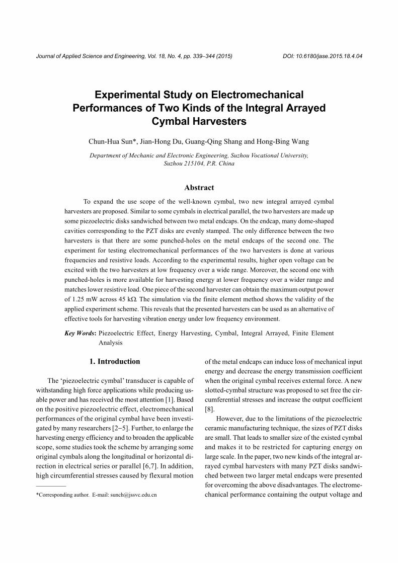
In order to simplify the subsequent arrangement of
the original cymbals in series or parallel, an innovative
structure, which is named the integral arrayed cymbal
harvester, is proposed, as shown in Figure 1. The harve-
sters are made up some PZT disks sandwiched between
two metal endcaps, on which there are evenly punched
dome-shaped cavities corresponding to the PZT disks.
The arrayed distribution lists as following: 1 is on the cen-
ter; 6 are on the second circle at 60 degree spacing; 12 are
on the third at 30 degree. The diameter of the harvester is
100 mm. The spacing distance between adjacent cavities
is set as 20 mm along the horizontal axis.
The process flow of the first kind of harvester, as
shown in Figure 1(a) is addressed as following:
(1) �100 of circular endcap is manufactured via punch-
ing from aluminum metal sheet.
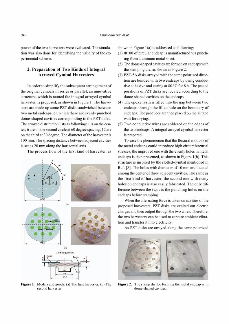
(2) The dome-shaped cavities are formed on endcaps with
the stamping die, as shown in Figure 2.
(3) PZT-5A disks arrayed with the same polarized direc-
tion are bonded with two endcaps by using conduc-
tive adhesive and curing at 80 �C for 8 h. The pasted
positions of PZT disks are located according to the
dome-shaped cavities on the endcaps.
(4) The epoxy resin is filled into the gap betweem two
endcaps through the filled hole on the boundary of
endcaps. The produces are then placed on the air and
wait for drying.
(5) Two conductive wires are soldered on the edges of
the two endcaps. A integral arrayed cymbal harvester
is prepared.
To ease the phenomenon that the flexural motions of
the metal endcaps could introduce high circumferential
stresses, the improved one with the evenly holes in metal
endcaps is then presented, as shown in Figure 1(b). This
structure is inspired by the slotted-cymbal mentioned in
Ref. [8]. The holes with diameter of 10 mm are located
among the center of three adjacent cavities. The same as
the first kind of harvester, the second one with many
holes on endcaps is also easily fabricated. The only dif-
ference between the twos is the punching holes on the
endcaps before stamping.
When the alternating force is taken on cavities of the
proposed harvesters, PZT disks are excited out electric
charges and then output through the two wires. Therefore,
the two harvesters can be used to capture ambient vibra-
tion and transfer it into electricity.
As PZT disks are arrayed along the same polarized
340 Chun-Hua Sun et al.
Figure 1. Models and goods: (a) The first harvester; (b) Thesecond harvester.
Figure 2. The stamp die for forming the metal endcap withdome-shaped cavities.
direction during the process of fabricating the harvesters,
the harvesters are similar to many original cymbal harve-
sters in electrical parallel. Owing to the advantages of the
original cymbal, the harvesters also possess the follow-
ing characteristics: more easily manufactured for saving
processing time, more suitable for scavenging large-scale
vibration. The following will test the electromechanical
properties of the two harvesters.
3. Experimental Results and Discussion
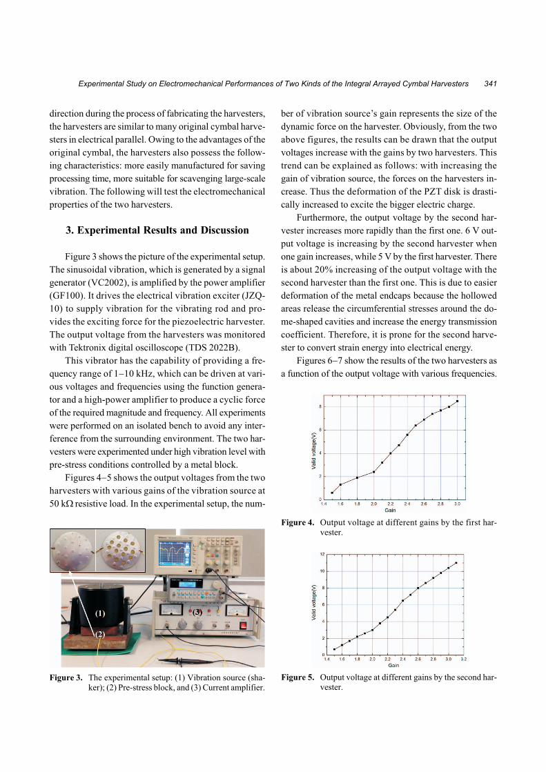
Figure 3 shows the picture of the experimental setup.
The sinusoidal vibration, which is generated by a signal
generator (VC2002), is amplified by the power amplifier
(GF100). It drives the electrical vibration exciter (JZQ-
10) to supply vibration for the vibrating rod and pro-
vides the exciting force for the piezoelectric harvester.
The output voltage from the harvesters was monitored
with Tektronix digital oscilloscope (TDS 2022B).
This vibrator has the capability of providing a fre-
quency range of 1�10 kHz, which can be driven at vari-
ous voltages and frequencies using the function genera-
tor and a high-power amplifier to produce a cyclic force
of the required magnitude and frequency. All experiments
were performed on an isolated bench to avoid any inter-
ference from the surrounding environment. The two har-
vesters were experimented under high vibration level with
pre-stress conditions controlled by a metal block.
Figures 4�5 shows the output voltages from the two
harvesters with various gains of the vibration source at
50 k� resistive load. In the experimental setup, the num-
ber of vibration source’s gain represents the size of the
dynamic force on the harvester. Obviously, from the two
above figures, the results can be drawn that the output
voltages increase with the gains by two harvesters. This
trend can be explained as follows: with increasing the
gain of vibration source, the forces on the harvesters in-
crease. Thus the deformation of the PZT disk is drasti-
cally increased to excite the bigger electric charge.
Furthermore, the output voltage by the second har-
vester increases more rapidly than the first one. 6 V out-
put voltage is increasing by the second harvester when
one gain increases, while 5 V by the first harvester. There
is about 20% increasing of the output voltage with the
second harvester than the first one. This is due to easier
deformation of the metal endcaps because the hollowed
areas release the circumferential stresses around the do-
me-shaped cavities and increase the energy transmission
coefficient. Therefore, it is prone for the second harve-
ster to convert strain energy into electrical energy.
Figures 6�7 show the results of the two harvesters as
a function of the output voltage with various frequencies.
Experimental Study on Electromechanical Performances of Two Kinds of the Integral Arrayed Cymbal Harvesters 341
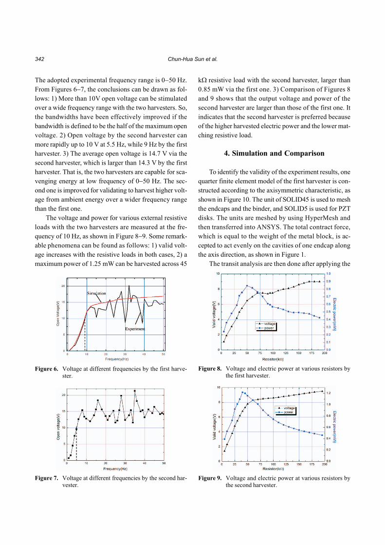
Figure 4. Output voltage at different gains by the first har-vester.
Figure 5. Output voltage at different gains by the second har-vester.
Figure 3. The experimental setup: (1) Vibration source (sha-ker); (2) Pre-stress block, and (3) Current amplifier.
The adopted experimental frequency range is 0�50 Hz.
From Figures 6�7, the conclusions can be drawn as fol-
lows: 1) More than 10V open voltage can be stimulated
over a wide frequency range with the two harvesters. So,
the bandwidths have been effectively improved if the
bandwidth is defined to be the half of the maximum open
voltage. 2) Open voltage by the second harvester can
more rapidly up to 10 V at 5.5 Hz, while 9 Hz by the first
harvester. 3) The average open voltage is 14.7 V via the
second harvester, which is larger than 14.3 V by the first
harvester. That is, the two harvesters are capable for sca-
venging energy at low frequency of 0�50 Hz. The sec-
ond one is improved for validating to harvest higher volt-
age from ambient energy over a wider frequency range
than the first one.
The voltage and power for various external resistive
loads with the two harvesters are measured at the fre-
quency of 10 Hz, as shown in Figure 8�9. Some remark-
able phenomena can be found as follows: 1) valid volt-
age increases with the resistive loads in both cases, 2) a
maximum power of 1.25 mW can be harvested across 45
k� resistive load with the second harvester, larger than
0.85 mW via the first one. 3) Comparison of Figures 8
and 9 shows that the output voltage and power of the
second harvester are larger than those of the first one. It
indicates that the second harvester is preferred because
of the higher harvested electric power and the lower mat-
ching resistive load.
4. Simulation and Comparison
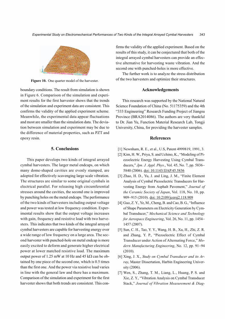
To identify the validity of the experiment results, one
quarter finite element model of the first harvester is con-
structed according to the axisymmetric characteristic, as
shown in Figure 10. The unit of SOLID45 is used to mesh
the endcaps and the binder, and SOLID5 is used for PZT
disks. The units are meshed by using HyperMesh and
then transferred into ANSYS. The total contract force,
which is equal to the weight of the metal block, is ac-
cepted to act evenly on the cavities of one endcap along
the axis direction, as shown in Figure 1.
The transit analysis are then done after applying the
342 Chun-Hua Sun et al.
Figure 6. Voltage at different frequencies by the first harve-ster.
Figure 7. Voltage at different frequencies by the second har-vester.
Figure 8. Voltage and electric power at various resistors bythe first harvester.
Figure 9. Voltage and electric power at various resistors bythe second harvester.
boundary conditions. The result from simulation is shown
in Figure 6. Comparison of the simulation and experi-
ment results for the first harvester shows that the trends
of the simulation and experiment data are consistent. This
confirms the validity of the applied experiment scheme.
Meanwhile, the experimental data appear fluctuations
and most are smaller than the simulation data. The devia-
tion between simulation and experiment may be due to
the difference of material properties, such as PZT and
epoxy resin.
5. Conclusions
This paper develops two kinds of integral arrayed
cymbal harvesters. The larger metal endcaps, on which
many dome-shaped cavities are evenly stamped, are
adopted for effectively scavenging large scale vibration.
The structures are similar to some original cymbals in
electrical parallel. For releasing high circumferential
stresses around the cavities, the second one is improved
by punching holes on the metal endcaps. The performance
of the two kinds of harvesters including output voltage
and power was tested at low frequency condition. Exper-
imental results show that the output voltage increases
with gain, frequency and resistive load with two harve-
sters. This indicates that two kinds of the integral arrayed
cymbal harvesters are capable for harvesting energy over
a wide range of low frequency on a large area. The sec-
ond harvester with punched-hole on metal endcap is more
easily excited to deform and generate higher electrical
power at lower matched resistive load. The maximum
output power of 1.25 mW at 10 Hz and 45 k� can be ob-
tained by one piece of the second one, which is 0.5 times
than the first one. And the power via resistive load varies
in line with the general law and there has a maximum.
Comparison of the simulation and experiment for the first
harvester shows that both trends are consistent. This con-
firms the validity of the applied experiment. Based on the
results of this study, it can be conjectured that both of the
integral arrayed cymbal harvesters can provide an effec-
tive alternative for harvesting waste vibration. And the
second one with punched-holes is more effective.
The further work is to analyze the stress distribution
of the two harvesters and optimize their structures.
Acknowledgements
This research was supported by the National Natural
Science Foundation of China (No. 51175359) and the 4th
“333 Engineering” Research Funding Project of Jiangsu
Province (BRA2014086). The authors are very thankful
to Dr. Jian Yu, Function Material Research Lab, Tongji
University, China, for providing the harvester samples.
References
[1] Newnham, R. E., et al., U.S, Patent 4999819, 1991, 3.
[2] Kim, H. W., Priya, S. and Uchino, K., “Modeling of Pi-
ezoelectric Energy Harvesting Using Cymbal Trans-
ducers,” Jpn. J. Appl. Phys., Vol. 45, No. 7, pp. 5836�
5840 (2006). doi: 10.1143/JJAP.45.5836
[3] Zhao, H. D., Yu, J. and Ling, J. M., “Finite Element
Analysis of Cymbal Piezoelectric Transducers for Har-
vesting Energy from Asphalt Pavement,” Journal of
the Ceramic Society of Japan, Vol. 118, No. 10, pp.
909�915 (2010). doi: 10.2109/jcersj2.118.909
[4] Guo, Z. Y., Ye, M., Cheng, B. and Cao, B. G., “Influence
of Shape Parameters on Electricity Generation by Cym-
bal Transducer,” Mechanical Science and Technology
for Aerospace Engineering, Vol. 26, No. 11, pp. 1454�
1457 (2007).
[5] Sun, C. H., Tao, Y. Y., Wang, H. B., Xu, H., Zhi, Z. R.
and Zhang, Y. P., “Piezoelectric Effect of Cymbal
Transducer under Action of Alternating Force,” Mo-
dern Manufacturing Engineering, No. 12, pp. 91�94
(2010).
[6] Xing, J. X., Study on Cymbal Transducer and its Ar-
ray, Master Dissertation, Harbin Engineering Univer-
sity (2006).
[7] Wen, S., Zhang, T. M., Liang, L., Huang, P. S. and
Xie, Z. Y., “Vibration Analysis on Cymbal Transducer
Stack,” Journal of Vibration Measurement & Diag-
Experimental Study on Electromechanical Performances of Two Kinds of the Integral Arrayed Cymbal Harvesters 343
Figure 10. One quarter model of the harvester.

nosis, Vol. 31, No. 3, pp. 295�299 (2011).
[8] Yuan, J. B., Shan, X. B, Xie, T. and Chen, W. S., “Energy
Harvesting with a Slotted-cymbal Transducer,” Journal
of Zhejiang University SCIENCE A, Vol. 10, No. 8, pp.
1187�1190 (2009). doi: 10.1631/jzus.A0920183
Manuscript Received: Apr. 17, 2015
Accepted: Sep. 21, 2015
344 Chun-Hua Sun et al.