experimental study on inclined planetary mechanism ... · experimental study on inclined planetary...
TRANSCRIPT

Experimental Study on Inclined Planetary Mechanism Drilling for Carbon Fiber Reinforced Plastic
Hidetake Tanaka1, Kazuki Ota1, Ryo Takizawa2, and Kazuhisa Yanagi1
1 Nagaoka University of Technology, Nagaoka, Japan 2 N.S.S Co., Ojiya, Japan
Abstract – The study deals with a proposal of a new drilling technique for CFRP. The authors have modified cutting mechanism principle of the orbital drilling, named inclined planetary drilling. Its axis of tool rotation spindle is not parallel to the axis of planetary revolution. The inclined angle is adjustable from 0 to 2 degrees. Because of tool rotation axis is inclined, penetration is not caused by
outermost cutting edges but inner cutting edges. If penetration could be occurred, the inner cutting edges penetrate firstly, then the outermost edges enlarge drilled hole and these sequence can avoid generation of delaminations and burrs. The inclined planetary
drilling has been demonstrated by the fundamental drilling experiment by use of a high-speed spindle unit and a lathe. And practical inclined planetary mechanism drilling system has developed. From the experimental result, capability of inclined planetary drilling
has been realized and no burrs and delaminations are observed on the workpiece.
Key Words: CFRP, Planetary drilling, Inclined milling, Spindle
1. IntroductionRecently, CFRP (Carbon Fiber Reinforced Plastic) are widely used
as structural material in aviation industries because of their advantages such as lightweight and high strength. However, those materials are mostly difficult to machine in conventional drilling techniques. The orbital drilling [1][2] has been realized as one of these solutions. The orbital drilling is similar to helical milling by machining center. In the case of the orbital drilling a cutting tool is settled on a tool rotation spindle eccentrically from a planetary revolution spindle and it rotates independently. The holes machined by the orbital drilling have higher roundness than holes machined by helical milling or conventional drilling.
The authors had established cutting model of the orbital drilling and clarified its machinability and proposed the cutting tools having particular cutting edge for CFRP drilling according to the past studies.[3-5] The orbital drilling has some drawbacks, e.g., delaminations of workpiece by its cutting principle and mechanical vibration.
In order to bring solutions to the orbital drilling technique, the authors have modified cutting mechanism principle of the orbital drilling which named as the inclined planetary drilling. Its axis of tool rotation is not parallel to the axis of planetary revolution. The inclined angle is adjustable from 0 to 2 degrees. In the case of the orbital drilling, the outermost cutting edges penetrate workpiece and the bottom layer is delaminated. On the other hand, in the case of the inclined planetary drilling, penetration is caused by the inner cutting edges not the outermost cutting edges because of inclined tool rotation axis. When penetration occurred, the inner cutting edges penetrate firstly then the outermost edges enlarge the drilled hole and the sequence can avoid generation of delaminations and burrs. In addition, inclined tool axis can reduce cutting force and mechanical vibration by its principle. Above-mentioned properties of the inclined planetary drilling have been demonstrated by the practical fundamental drilling experiment by use of a high-speed spindle unit and a lathe as imitating
inclined planetary motion. Furthermore, a novel spindle unit of inclined planetary mechanism drilling has been developed on the basis of the fundamental research results.
From the experimental result, capability of inclined planetary drilling has been realized and no burrs and delaminations are observed on the workpiece.
2. Cutting edge motion of planetary drilling We focused on a bottom edge motion on a cutting tool of the orbital
drilling which may inferentially affect machinability of CFRP drilling. A cutting edge on the bottom face is expressed as 2 position vectors summation as show in figure 1.
The velocity of a cutting edge on the bottom face depends on planetary revolution speed and tool rotation speed. Distribution of the velocity is not constant as shown in figure 2.
An angle between the line to tool center to planetary revolution center and the line to tool center to the point is named angular difference and it can be also a significant factor. Direction of tool rotation around planetary revolution center is CCW and direction of tool rotation speed on its center axis is CW.
rt
Tool center
ro
Cutting edge
Planetary revolution
Fig. 1 Geometrical model of orbital drilling cutting edge
ISUPEN 2013 International Symposium on Ultraprecision Engineering and Nanotechnology, Tokyo, Japan, March 13, 2013.
23
Invited paper

Velocity of the cutting edge by tool rotation (vs) is defined by the eq. (1) where rt stands for tool radius and Tss stands for tool rotation speed.
vs = 2� Tss rt (1)
Velocity of the point by planetary revolution speed (vo) is defined by the eq. (2) where ro stands for eccentricity and Os stands for planetary revolution speed.
vo = 2� Os ro (2)
From eq. (1) and (2), the velocity of cutting edge is calculated and the result is shown in figure 2. In the case of these parameters, Os and ro are larger than actual orbital drilling parameter in order to ensure the effect of orbital motion. Figure 2(c) shows the result in 0°. vs and vo cancel them each other when it is no angular difference. The zero velocity point on bottom face can appear continuously and moving around on the bottom cutting edge. Therefore it makes thrust loading larger.
In the case of conventional drilling, drilling resistance becomes larger at the centre of chisel point where the cutting edge speed theoretically being zero. Beside, the planetary revolution made direction of the cutting edge velocity reversed at a singular point of the bottom edge. The radius range where the singular point existing is defined as counter velocity radius (rn). The counter velocity radius might cause cutting resistance larger and negative effect to the machinability.
Counter velocity radius (rt) in planetary drilling is defined by planetary revolution speed (Os), eccentricity (ro) and tool rotation speed (Tss).
Tool cutting edge speed from planetary motion speed is defined by the eq. (3).
vo = 2�Os( rt +ro ) (3)
If vo becomes equal to vs in zero velocity point,
vo = vs (4)
2 Os( rt +ro )= 2�Tss rt (5)
2 Os rn ( 1+ro / rn )= 2�Tss rn (6)
Consequently, the counter velocity radius of bottom edge in orbital drilling is defined by eq. (7).
rn = ro /(Tss /Os -1 ) (7)
The cutting edge can not machine effectively where the inner area of tool radius = rn on the bottom surface of cutting tool. Thus machining with the zero cutting velocity point and the inner area of counter velocity radius should be avoided as far as possible in order to improve the machinability of the orbital drilling.
3. Inclined planetary drilling The oblique cutting is generally known as one of machinability
improvements of ball end-mill. Machining at the zero velocity point(tip of ball end-mill) is avoided by tiled tool rotational axis. We have adopted the same concept to the planetary drilling motion. Figure 3 shows differences between the orbital drilling model and our innovated inclined planetary drilling. In the case of the inclined planetary drilling, the tool rotational axis is inclined, in another words, the tool rotational axis is not parallel to the planetary revolution axis.
(a) Cutting edge on the bottom face
Planetary revolution center
Tool center
Planetary revolution motion
Spindle rotation
Angular difference
Velocity by tool rotation
Velocity by planetary revolution rotation
Composition velocity by 2 rotations
(b) Cutting edge angle = 45
1m/sec
( ) Cutting edge angle = 0
Zero velocity point
Fig. 2 Cutting edge velocity components
Counter velocity radius
Spindle rotation Tool center
(b) Angular difference = 45
(c) Angular difference = 0
(a) Orbital drilling (b) Inclined planetary drilling Fig. 3 Schematic view of orbital and inclined planetary drilling
Cutting toolCutting tool
Workpiece Workpiece
Feed Feed
Tool rotation Tool rotation
Tool length
Revolution Revolution
Eccentricity Eccentricity
θ
24
ISUPEN 2013 International Symposium on Ultraprecision Engineering and Nanotechnology, Tokyo, Japan, March 13, 2013.
Invited paper

The counter velocity radius is calculated by eq. (7) with drilling conditions which are ro, Tss and Os. For example; assuming practical drilling, counter velocity radius rn = 0.02mm with the conditions of fundamental experimental result where ro = 2, Tss = 30,000, Os = 300. Then, figure 4 shows model of oblique cutting with ball end-mill. Here, tilt angle is � and rnt is radius of first contact position to a workpiece surface of a ball end-mill. Supposing practical inclined planetary drilling condition, � = 3 and rt = 3. rn = 0.157mm and it is enough to avoid the counter velocity radius. The inclined planetary drilling can accordingly improve machinability in stead of the commercial orbital drilling technique.
The other inevitable problem of the orbital drilling is delaminations and burrs on the exit edge of drilled holes. By using of the orbital drilling, delaminating and burrs are generated in principle as shown in figure 5 left. In the case of the orbital drilling, the outermost cutting edge is the first penetration point of tool on backside of a workpiece. And thin layer of workpiece can be peeled off when penetrating and that causes delamination and burr on the edge. On the other hand in the case of inclined planetary drilling, the first penetration is not caused by the outermost cutting edge but inner cutting edge. If delaminating and burrs could be occurred when penetrating, the outermost cutting edge would make the drilled hole deburred as shown in figure 5 right.
The diameter of a drilled hole by inclined planetary drilling is defined by geometrical parameters of the tiled planetary drilling instrument configuration as shown in figure 6. Significant parameters are rt; tool radius, TL; tool length and �; inclined angle. The diameter of a drilled hole (D) is calculated by eq. (8). Especially this equation can be used restricted utilization for ball end-mills. Utilizing a ball end-mill does have control the diameter of the drilled hole simple.
D = 2(rt + TL tan� ) (8)
4. Experiment In order to evaluate capability of the inclined planetary drilling,
fundamental drilling experiments by using of a lathe and high-speed spindle unit have been carried out. Layout of the experimental apparatuses is shown in figure 7. A jig with a workpiece (CFRP) is fixed on the main spindle of a lathe and a high-speed spindle unit is attached to the tool post instead of turning tools. The tool post can adjust tilting angle against feed direction. In this case, the main spindle rotation of the lathe performs as the planetary revolution. Eccentricity x is calculated by eq. (9) as shown in figure 8.
x = L2 sin � – L1(1-cos �) (9)
CFRP (PAN-Based Carbon Fiber; Specific gravity: 1.5, Tensile strength: 1.6kN, Young s modulus: 120GPa, Glass transition point: 120 ) plates (50mm square, thickness: 5mm) are prepared as experimental workpieces. In this case, inclined angle is 2 degree as same as the eccentricity: 2mm. The experiment has been carried out
Fig.4 Oblique cutting with ball end-mill
Fig.6 Geometrical model of inclined planetary drilling
Fig.5 Generation of burrs and delaminations
x
Fig.7 Whole view of experimental apparatuses
Fig.8 Geometry of drilling experimental instruments
ISUPEN 2013 International Symposium on Ultraprecision Engineering and Nanotechnology, Tokyo, Japan, March 13, 2013.
25
Invited paper

under the conditions as shown in table 1. Especially, drilling feeding moved forward only.
A ball end-mill is logically decided as optimum cutting tools based on the geometrical cutting model of inclined planetary drilling.
In order to distinguish usability of the inclined planetary drilling technique from the orbital drilling, experiment for comparing inclined planetary drilling with orbital drilling is carried out. Drilling condition is as same as shown in table 1. The ball type cutting tool is selected for the experiment by use of the orbital technique.
5. Experimental results First of all, drilled holes are inspected visually to find burrs and
delaminations on the edge. Figure 9 shows the difference of drilled holes appearance by the orbital drilling and inclined planetary drilling. Smooth finishing is observed and there are no burrs and delaminations on the edge by the inclined planetary drilling. On the other hand, in the case of the orbital drilling, burrs are occurred around the hole on the both sides.
Surface roughness of drilled workpiece is measured by using of a surface roughness measurement instrument. Measured direction is parallel to the axis of the hole and surface roughness parameters are calculated by average of four measured parts of three times trial results. The measuring results indicate that the inclined planetary drilling can drill with smoothest surface from the point of view of surface roughness as shown in table 2. At least it is found that the inclined planetary drilling can drill with smoother surface roughness than by using of the orbital drilling.
Roundness of drilled hole is measured by using of roundness
measuring instrument. Roundness strongly depend on the surface roughness, in other words, the smoother surface roughness it have, the better roundness is obtained by using of same experimental instruments. Table 3 shows the measurement result of roundness. From the fundamental experimental result, the inclined planetary drilling having availability of smoother drilling than the orbital drilling is clarified.
6. Inclined planetary mechanism drilling system The advantages of the inclined planetary mechanism drilling have
been demonstrated through the experiment by use of a lathe. From the point of view of practical CFRP drilling factory e.g. aviation and aero-space industry, the size of workpieces to be drilled is much larger than the test specimens. Practical CFRP drilling equipments require following features; 1. The size is enough small and light to handle by human operators. 2. The drilling machine can drill the workpiece without another machine tool. 3. The drilling machine can attach to an industrial robot as an end-effecter.
We have designed a new small size spindle unit for the inclined planetary drilling, which consists of a novel inclination mechanism. Figure 10 shows schematic views of the eccentric mechanism by inclination. The eccentric mechanism of the inclined planetary drilling system is multi-cylinder mechanism. Figure 10(a) and 2(b) shows the concentric state and eccentric inclined state, respectively. Frame a (Xa,Ya, Za) is Cartesian coordinate system with origin at the center of the outer cylinder. Frame b (Xb, Yb, Zb) is Cartesian coordinate system with origin at the center of the inner cylinder. Frame b has inclined �as the Ya-axis from frame a.
At this point, the tool tip position vector after eccentric is defined by the Eq. (10) where, l stands for length of the inner cylinder and ti
stands for tool length and � stands for distance that the axis of rotation was mapped to the top end surface from the center of the inner cylinder and � stands for the rotation angle around the Zb of frame b.
Table 1 Experimental conditions Cutting tool (Cemented carbide) R=4mm, ball end-mill
Eccentricity (Inclined angle) 2 mm (2 )
Planetary revolution speed 560 min-1
Tool rotation speed 28000 min-1
Feed rate 30 mm/min
Number of trial 3
Fig.9 Apperance of drilled holes
Table 2 Surface roughness of drilled holes Ra [�m] Rz [�m]
Inclined planetary drilling 1.17 8.41
Planetary drilling 1.20 12.05
Table 3 Measured results of roundness Roundness [�m]
Inclined planetary drilling 14.60
Planetary drilling 17.89
Fig. 10 Eccentric mechanism model
26
ISUPEN 2013 International Symposium on Ultraprecision Engineering and Nanotechnology, Tokyo, Japan, March 13, 2013.
Invited paper
�����
�
�
�
���
�
��
�����
�
�
�
�
1
sincos
21
10000cos0sin00100sin0cos
2l
la
lt
Pt����
��
��
(10)
Therefore, the center position of the tool tip(aPt) and the eccentricity(e) are as follows:
� �
� � ��������
�
�
�
���
�
� �
���
�
� �
���
�
� ��
�
22
costansincos
sintan22
sin22
cos1
l
l
l
a
tl
tl
tl
Pt
����
��
��
(11)
� �22
sintan22
sin22
cos1��
���
��
���
���
�
� ��
��
���
��
���
���
�
� ��� ���� ll tltl
e (12)
Figure 11 shows the 3D model on CAD, and figure 12 shows the calculation result of the eccentricity where, l is 150 mm and tl is 50 mm. In addition, the acceleration was simulated by use of the 3D model (figure 11) where, revolution speed is 200 /min and e is 3 mm.
The eccentricity which � is 3 degrees confirmed to increase linear in the range of 0-35 degrees and, the acceleration is 3.8 mm/s2. When � is 2 degrees, the necessary range of � is increase and linearity is lost. In other words, the eccentricity can be obtained while keeping small dmore when � is 3 degrees. Also, the acceleration is 3.1 mm/s2 which �is 2 degrees. There was not a significant difference. Therefore, we are considered as desirable that � is 3 degrees.
Fig. 11. 3D model of the eccentric mechanism
-0.5
0
0.5
1
1.5
2
2.5
3
3.5
4
4.5
0 10 20 30 40 50
Phase angle � [deg]
Ecce
ntric
ity e
[mm
]
-0.05
0
0.05
0.1
0.15
0.2
0.25
0.3
0.35
0.4
0.45
Diff
eren
ce b
etw
een
the
linea
rity
d [m
m]e ( �= 3 deg )
e ( �= 2 deg )d ( �= 3 deg )d ( �= 2 deg )
Fig. 12. Calculation result of the eccentricity
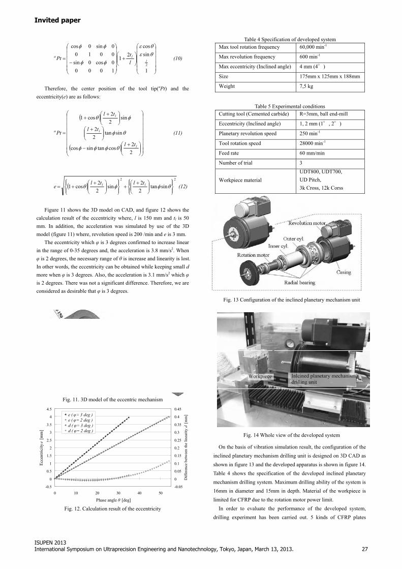
On the basis of vibration simulation result, the configuration of the inclined planetary mechanism drilling unit is designed on 3D CAD as shown in figure 13 and the developed apparatus is shown in figure 14. Table 4 shows the specification of the developed inclined planetary mechanism drilling system. Maximum drilling ability of the system is 16mm in diameter and 15mm in depth. Material of the workpiece is limited for CFRP due to the rotation motor power limit.
In order to evaluate the performance of the developed system, drilling experiment has been carried out. 5 kinds of CFRP plates
Table 4 Specification of developed system Max tool rotation frequency 60,000 min-1
Max revolution frequency 600 min-1
Max eccentricity (Inclined angle) 4 mm (4 )
Size 175mm x 125mm x 188mm
Weight 7,5 kg
Table 5 Experimental conditions Cutting tool (Cemented carbide) R=3mm, ball end-mill
Eccentricity (Inclined angle) 1, 2 mm (1 , 2 )
Planetary revolution speed 250 min-1
Tool rotation speed 28000 min-1
Feed rate 60 mm/min
Number of trial 3
Workpiece material UDT800, UDT700, UD Pitch, 3k Cross, 12k Corss
Cutting tool
Revolution motor
Feeding stage
Fig. 13 Configuration of the inclined planetary mechanism unit
Fig. 14 Whole view of the developed system
ISUPEN 2013 International Symposium on Ultraprecision Engineering and Nanotechnology, Tokyo, Japan, March 13, 2013.
27
Invited paper

(50mm square, thickness: 5mm) are prepared as experimental workpieces as shown in Table 5. In this case, eccentricity is 1 or 2 mm. The experimental conditions are shown in table 5.
Drilled holes are inspected visuall. Figure 15 shows the appearance of drilled holes. Smooth finishing is observed generates no burrs and delaminations on the edge except for UDT800 and 12k Cross. On the other hand, in the case of UDT800 and 12k Cross, burrs are occurred around the hole on both sides. It seems that the fiber filler having high tensile strength is hard to cut off with the normal ball end-mill.
Surface roughness of drilled workpiece is measured. Measured direction is parallel to the axis of the hole and surface roughness parameters are calculated by average of four measured parts of three times trial results. The measuring results indicate that larger
eccentricity made surface roughness worse as shown in table 6. Table 7 shows the measurement result of roundness. Roundness
strongly depends on the trend of surface roughness except for UDT800. And especially, roundness of UDT800 is worst because of the same reason of the fiber filler.
From the experimental result, the developed inclined planetary mechanism drilling system having availability of smooth drilling is demonstrated. In order to improve the drilled holes quality of UDT800 and 12k Cross, a cutting tool coated by diamond CVD or PCD tool as well as suitable drilling conditions for them is required.
7. Summary � In order to improve machinability of orbital drilling, inclined
planetary drilling has been established according to the analytical result of the motion of bottom cutting edge of orbital drilling.
� Fundamental drilling experiments that imitate the motion of inclined planetary drilling with a lathe have been carried out.
� Experiment for comparing inclined planetary drilling with orbital drilling is carried out. From the experimental result, the superiority of the inclined planetary drilling is clarified.
� From the experimental result, the developed inclined planetary mechanism drilling system having availability of smoother drilling than the orbital drilling is demonstrated.
References [1] http://www.novator.nu/ [2] E.Brinksmeier, Sascha Fangmann, I.Meyer. 2010. Production Engineering Research and Development. 2:277-283 [3] NEBUKA Teppei, TANAKA Hidetake, and YANAGI Kazuhisa., 2007, Proceedings of Asia symposium for Precision Engineering and Nanotechnology, 309-312. [4] ISHIBASHI Tatsuya, TANAKA Hidetake, and YANAGI Kazuhisa., 2009, An analytical model for orbital drilling and its applicability to, Proceedings of the Twenty-Fourth Annual Meeting of the American society for Precision Engineering. [5] Hidetake TANAKA, Shinji Obata and Kazuhisa YANAGI, Optimization of cutting edge configuration and machining conditions in orbital drilling, Proceedings of 4th CIRP International Conference on High Performance Cutting, 2010, p. 201-206
Fig. 15 Appearances of drilled hole by developed inclined planetary mechanism drilling unit
Table 6 Measurement results of surface roughness Material Ra [�m] Rz [�m]
UDT800 1.76 31.18
UDT700 0.70 6.56
UD Pitch 0.93 19.08
3k Cross 0.67 6.91
Eccentricity :
1 mm
12k Cross 0.70 8.17
UDT800 2.33 41.93
UDT700 0.84 7.96
UD Pitch 1.20 22.22
3k Cross 0.91 8.50
Eccentricity :
2 mm
12k Cross 0.86 8.76
Table 7 Measurement results of roundness Material Roundness [�m]
UDT800 4.85
UDT700 3.85
UD Pitch 4.52
3k Cross 5.03
Eccentricity :
1 mm
12k Cross 5.94
UDT800 5.11
UDT700 4.48
UD Pitch 6.15
3k Cross 7.32
Eccentricity :
2 mm
12k Cross 9.06
28
ISUPEN 2013 International Symposium on Ultraprecision Engineering and Nanotechnology, Tokyo, Japan, March 13, 2013.
Invited paper