experimental study on the fundamental mechanical …
TRANSCRIPT

Advanced Steel Construction Vol. 13, No. 2, pp. 96-116 (2017) 96
EXPERIMENTAL STUDY ON THE FUNDAMENTAL MECHANICAL FEATURES OF CABLE-SUPPORTED RIBBED
BEAM COMPOSITE SLAB STRUCTURE
Wentao Qiao1,* , Qi An2, Mingshan Zhao3 and Dong Wang4
1Associate Professor, School of Civil Engineering, Shi Jiazhuang Tiedao University, China 2PhD. Student, School of Civil Engineering, Tianjin University, China
3Research Fellow, School of Civil and Environmental Engineering, Nanyang Technological University, Singapore 4PhD. Student, Department of Civil and Environmental Engineering, UAH, Huntsville, United States
*(Corresponding author: E-mail: [email protected])
Received: 15 October 2015; Revised: 14 April 2016; Accepted: 30 April 2016
ABSTRACT: In this study, experiments were carried out to investigate the fundamental mechanical features of the cable-supported ribbed beam composite slab structure (CBS). A 1:5 scaled physical model was designed, fabricated and tested. The feasibility and rationality of the CBS fabrication and construction are discussed and justified. The theoretical analysis used to predict the deflection and member forces is verified. It is shown that the CBS is equipped with high stiffness and behaves linearly in terms of force-displacement relationship and all the cable forces, structural deformation, stress of the ribbed beam and strut stresses are symmetrically distributed. Through comparison analysis, the mechanical features of each span are found to be similar and each span can be considered as a relatively independent mechanical unit. When the CBS is loaded, the stresses in the ribbed beam increase gradually from the two ends towards the center, where the maximum stress and deformation locates eventually, while the distribution of cable forces and strut stresses is the other way around. Further monitoring also shows that the temperature effect on the CBS is not significant since the interior constraint forces are self-balanced by the self-adjustable support. Keywords: Cable-supported ribbed beam composite slab, mechanical features, pre-stress, fabrication, experimental
research DOI: 10.18057/IJASC.2017.13.2.1
1. INTRODUCTION The merits of cable-supported spatial structure systems [1] come from the combination of rigid structures such as shell, grid structure and flexible structures such as cable network structures [2, 3]. Because of the action of the pre-stressed cables, such systems are highly efficient in load-deformation performance and usually self-balanced. The cable-supported spatial structure systems including beam (truss) string structure [4-7], suspend-dome structure [8, 9], and cable-supported barrel vault structure [10-13], have been widely used in the public buildings around the world. The cable-supported ribbed beam composite slab structure (CBS) is one of such structures that effectively utilize different building materials. The concept of the CBS was put forward by Chen and Qiao [14] for the first time. They investigated the basic static and dynamic features by using numerical simulation method. Later, Qiao et al. [15] presented the construction method of the CBS and fabricated a bamboo model to study the basic static and dynamic characteristics. This structure consists of the upper concrete slab, middle struts and lower cables. The struts behave as flexible supports between the upper concrete slab and lower cables, transferring loads between these two. Due to mechanical benefits by this configuration, CBS can easily span long distance when used as floor or roof systems. In this study, experiments were carried out to investigate the fundamental mechanical features of the cable-supported ribbed beam composite slab structure (CBS). A 1:5 scaled physical model was designed, fabricated and tested. The feasibility and rationality of the CBS fabrication, the precision

97 Experimental Study on the Fundamental Mechanical Features of Cable-Supported Ribbed Beam Composite Slab Structure
of the theoretical analysis method and the mechanical behavior of the CBS are discussed. The rest of this paper is organized as follows: Section 2 describes the basic fabrication and construction processes of the CBS. Section 3 discusses the basic mechanical features of CBS theoretically, including self-balanced system and pre-stress design method. Section 4 determines the 1:5 scaled experimental model, loading scheme and data collecting method. In order to figure out the actual mechanical features of the CBS in detail, the monitored data including deformation, cable force, strut stress and ribbed beam stress are also analyzed in section 5. 2. FABRICATION 2.1 Connection Design From top to bottom, the CBS consists of the upper reinforced concrete slab, ribbed beam, the middle steel strut, and the lower cable, as shown in Figure 1. All the members are prefabricated and assembled on site. Pin-pin joints are used for most of the connections, and a special joint is designed for the connection between the strut and the beam, as shown in Figure 2. This configuration grants the whole connection the ability to rotate in multiple directions: the upper pin joint can rotate about the longitudinal direction of the cable, while the lower pin joint is used to adjust the angle of strut so that it can be fit into the support easily. Obviously, this configuration enables efficient and effective load transfer between cables and upper deck. At the both ends of the cable, another pin joint is used to fix the cable into the anchorage, as shown in Figure 3.
Figure 1. Fabrication of Unit Figure 2. Strut Junction
Figure 3. Anchorage of Cable End
Wentao Qiao, Qi An, Mingshan Zhao and Dong Wang 98
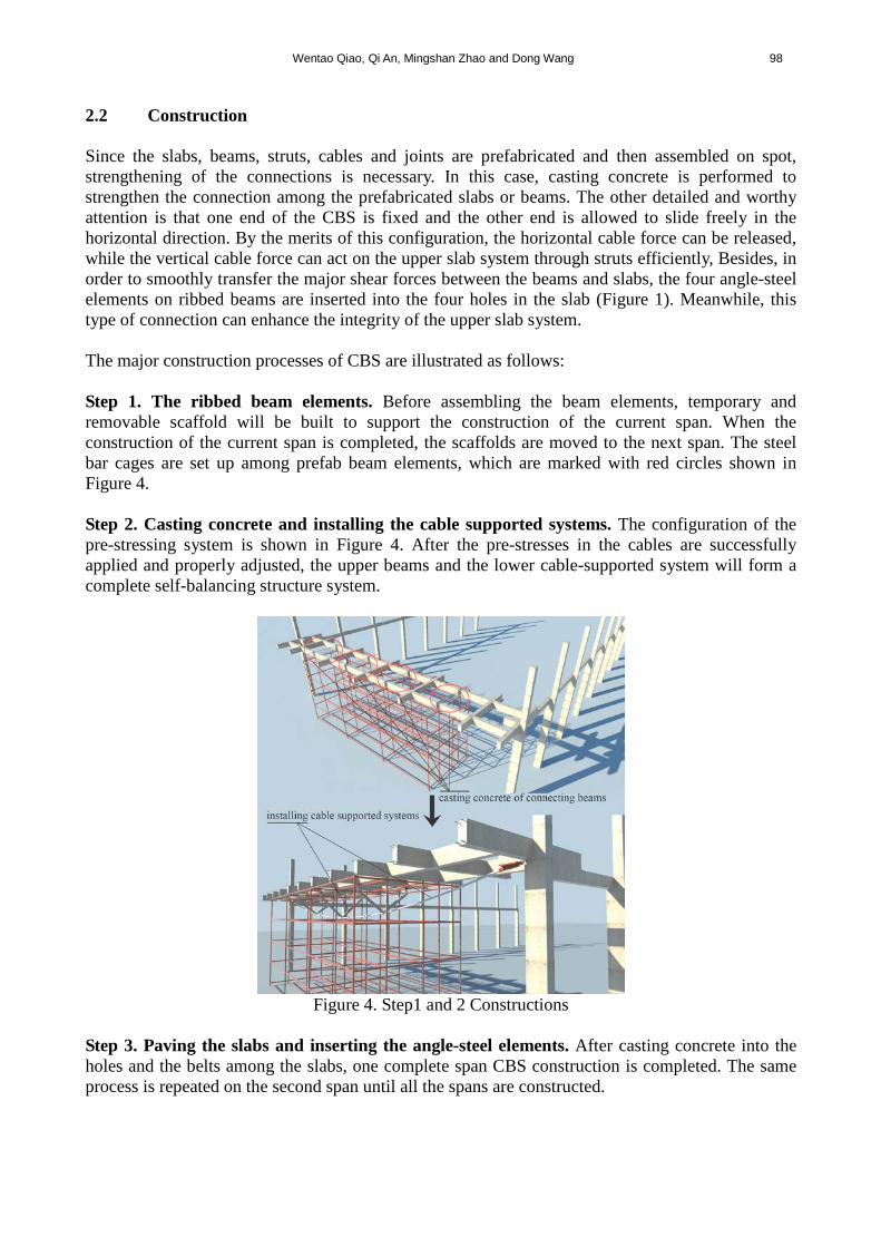
2.2 Construction Since the slabs, beams, struts, cables and joints are prefabricated and then assembled on spot, strengthening of the connections is necessary. In this case, casting concrete is performed to strengthen the connection among the prefabricated slabs or beams. The other detailed and worthy attention is that one end of the CBS is fixed and the other end is allowed to slide freely in the horizontal direction. By the merits of this configuration, the horizontal cable force can be released, while the vertical cable force can act on the upper slab system through struts efficiently, Besides, in order to smoothly transfer the major shear forces between the beams and slabs, the four angle-steel elements on ribbed beams are inserted into the four holes in the slab (Figure 1). Meanwhile, this type of connection can enhance the integrity of the upper slab system. The major construction processes of CBS are illustrated as follows: Step 1. The ribbed beam elements. Before assembling the beam elements, temporary and removable scaffold will be built to support the construction of the current span. When the construction of the current span is completed, the scaffolds are moved to the next span. The steel bar cages are set up among prefab beam elements, which are marked with red circles shown in Figure 4. Step 2. Casting concrete and installing the cable supported systems. The configuration of the pre-stressing system is shown in Figure 4. After the pre-stresses in the cables are successfully applied and properly adjusted, the upper beams and the lower cable-supported system will form a complete self-balancing structure system.
Figure 4. Step1 and 2 Constructions
Step 3. Paving the slabs and inserting the angle-steel elements. After casting concrete into the holes and the belts among the slabs, one complete span CBS construction is completed. The same process is repeated on the second span until all the spans are constructed.
99 Experimental Study on the Fundamental Mechanical Features of Cable-Supported Ribbed Beam Composite Slab Structure
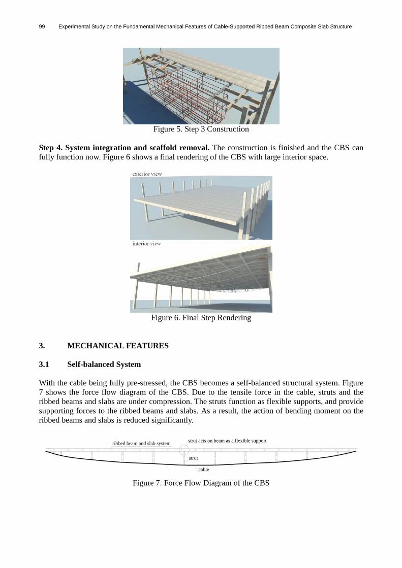
Figure 5. Step 3 Construction
Step 4. System integration and scaffold removal. The construction is finished and the CBS can fully function now. Figure 6 shows a final rendering of the CBS with large interior space.
Figure 6. Final Step Rendering
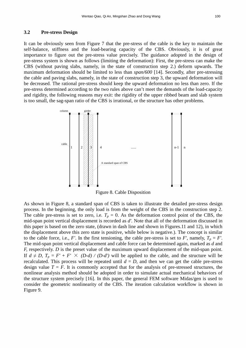
3. MECHANICAL FEATURES 3.1 Self-balanced System With the cable being fully pre-stressed, the CBS becomes a self-balanced structural system. Figure 7 shows the force flow diagram of the CBS. Due to the tensile force in the cable, struts and the ribbed beams and slabs are under compression. The struts function as flexible supports, and provide supporting forces to the ribbed beams and slabs. As a result, the action of bending moment on the ribbed beams and slabs is reduced significantly.
strut acts on beam as a flexible support
strut
cable
ribbed beam and slab system
Figure 7. Force Flow Diagram of the CBS
Wentao Qiao, Qi An, Mingshan Zhao and Dong Wang 100
3.2 Pre-stress Design It can be obviously seen from Figure 7 that the pre-stress of the cable is the key to maintain the self-balance, stiffness and the load-bearing capacity of the CBS. Obviously, it is of great importance to figure out the pre-stress value precisely. The guidance adopted in the design of pre-stress system is shown as follows (limiting the deformation): First, the pre-stress can make the CBS (without paving slabs, namely, in the state of construction step 2.) deform upwards. The maximum deformation should be limited to less than span/600 [14]. Secondly, after pre-stressing the cable and paving slabs, namely, in the state of construction step 3, the upward deformation will be decreased. The rational pre-stress should keep the upward deformation no less than zero. If the pre-stress determined according to the two rules above can’t meet the demands of the load-capacity and rigidity, the following reasons may exit: the rigidity of the upper ribbed beam and slab system is too small, the sag-span ratio of the CBS is irrational, or the structure has other problems.
cable
column girder
1 2 3 4 n-1 n......
A standard span of CBS
Figure 8. Cable Disposition
As shown in Figure 8, a standard span of CBS is taken to illustrate the detailed pre-stress design process. In the beginning, the only load is from the weight of the CBS in the construction step 2. The cable pre-stress is set to zero, i.e. Tp = 0. As the deformation control point of the CBS, the mid-span point vertical displacement is recorded as d'. Note that all of the deformation discussed in this paper is based on the zero state, (drawn in dash line and shown in Figures.11 and 12), in which the displacement above this zero state is positive, while below is negative.). The concept is similar to the cable force, i.e., F'. In the first tensioning, the cable pre-stress is set to F', namely, Tp = F'. The mid-span point vertical displacement and cable force can be determined again, marked as d and F, respectively. D is the preset value of the maximum upward displacement of the mid-span point. If d ≠ D, Tp = F' + F' × (D-d) / (D-d') will be applied to the cable, and the structure will be recalculated. This process will be repeated until d = D, and then we can get the cable pre-stress design value T = F. It is commonly accepted that for the analysis of pre-stressed structures, the nonlinear analysis method should be adopted in order to simulate actual mechanical behaviors of the structure system precisely [16]. In this paper, the general FEM software Midas/gen is used to consider the geometric nonlinearity of the CBS. The iteration calculation workflow is shown in Figure 9.

101 Experimental Study on the Fundamental Mechanical Features of Cable-Supported Ribbed Beam Composite Slab Structure
Cable pre-stress valueTp
Calculation model
Tp = 0
Calculate with dead load
Mid-span point vertical displacement: d'Cable force: F'
Calculation model
Tp = F'
Calculate with dead load
Mid-span point vertical displacement: dCable force: F
If d ≠ D
Tp = F' + F' × (D - d)/(D - d')
d = D
Cable pre-stress design valueT = F
(D = span/600)
Figure 9. Pre-stress Finding Iteration Workflow
In the process of calculating the cable pre-stress of CBS, sometimes it is not easy to converge to the completely precise preset value D, as shown in Figure 10. It is clearly seen that the mid-span point vertical displacement d is getting close to the objective D from the nth iteration step. With some delay, d also gets close to the D and keeps fluctuating. Therefore, a preset value close to D = span/600 can get reasonably close to the optimum. As shown in Figure 10, if a tiny error ±t is set (dash line in Figure 10), the non-convergent iteration curve will be able to converge at step n+1.
D = span / 600
n-1
n
n+1
iteration step
mid
-spa
npo
intv
ertic
aldi
sp. t
t
Figure 10. Convergence analysis
3.3 Prototype Analysis The gymnasium roof of Hebei Normal University in China is chosen as the calculation prototype. For this gymnasium, there are 13 standard spans and each span is 42.25m long. The standard span
Wentao Qiao, Qi An, Mingshan Zhao and Dong Wang 102
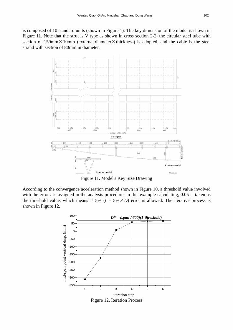
is composed of 10 standard units (shown in Figure 1). The key dimension of the model is shown in Figure 11. Note that the strut is V type as shown in cross section 2-2, the circular steel tube with section of 159mm×10mm (external diameter×thickness) is adopted, and the cable is the steel strand with section of 80mm in diameter.
500 250 250 250 250 250 250 250 250 5004000 4000 4000 4000
10×4000+9×250=42250
250250
250
250
250
250
4000
4000
13×4000+12×
250=55000
4000 4000250 4000250 250250 4000 4000100
500
500
250
400
100
400
4000
250
2000
1 1
2
2
Unit(mm)
21125×2=42250
bila
tera
l sym
met
ry
cable
strut
2000
Floor plan
Cross section 2-2
Cross section 1-1
Figure 11. Model's Key Size Drawing
According to the convergence acceleration method shown in Figure 10, a threshold value involved with the error t is assigned in the analysis procedure. In this example calculating, 0.05 is taken as the threshold value, which means ±5% (t = 5%×D) error is allowed. The iterative process is shown in Figure 12.
1 2 3 4 5 6-350
-300
-250
-200
-150
-100
-50
0
50
100
mid
-spa
n po
int v
ertic
al d
isp.
(mm
)
iteration step
D* = (span / 600)(1-threshold)
Figure 12. Iteration Process

103 Experimental Study on the Fundamental Mechanical Features of Cable-Supported Ribbed Beam Composite Slab Structure
It is obviously shown in Figure 12 that the iteration converges at the 6th step, and the mid-span point vertical displacement value is 67.6mm. Compared with the target value D = span/600, the error of the mid-span vertical displacement is only about 4%. Actually at the 5th iteration step the corresponding displacement value is 63.8mm, and the error is 9.4%, which is also acceptable as the pre-stress design value. In order to verify the rationality of the pre-stress design value, with this pre-stress applied to the cable, the deformation of the structure in the state of construction step 3 (described in section 2) is calculated. Apparently, the rational pre-stress may be a range of values, and the smaller one is preferred. At the 5th iteration value, the corresponding pre-stress design value is 1900kN. The deformation of the structure is illustrated in Figure 19. In construction step 3, the prefab concrete slabs will be paved on top of the ribbed beams. Because of the extra dead load of the slabs, the CBS in the construction step 2 equilibrium states will deform downwards, and the final deformation of the CBS is shown in Figure 20. The vertical displacement of the mid-span point is positive 15.4 mm which is still above the zero state, and can meet the demand of reasonable pre-stress design value described in section 3.2. Moreover, the internal force of the cable also increases because of the dead load of the concrete slabs. The calculated value is 2533 kN, which is 633 kN bigger than the tension 1900 kN in construction step 2. 4. EXPERIMENTAL SCHEME 4.1 Physical Model Based on the prototype introduced in section 3.3, a 1:5 scaled model is fabricated. The scale factors are worked out according to the similarity constant and similarity ratio relationship in static loading experiment of engineering structure [17]. For geometric dimensions shown in Figure 11, the ratio of scaled model to the full scale model is 1:5. For the cable tension and structural displacement, the ratio of scaled model to the full scale model is 1:25 and 1:5. The scaled physical model and its construction processes are shown in Figure 13. (3 standard spans are fabricated and tested)
Figure 13. Scaled Physical Model
Wentao Qiao, Qi An, Mingshan Zhao and Dong Wang 104
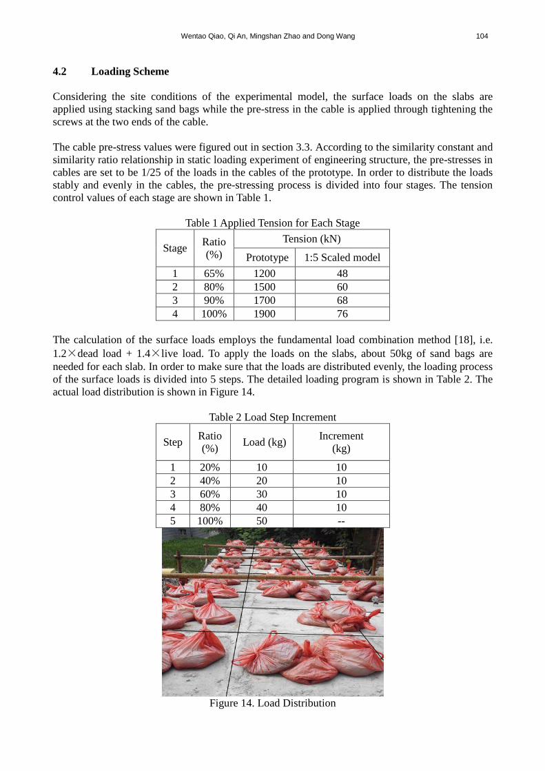
4.2 Loading Scheme Considering the site conditions of the experimental model, the surface loads on the slabs are applied using stacking sand bags while the pre-stress in the cable is applied through tightening the screws at the two ends of the cable. The cable pre-stress values were figured out in section 3.3. According to the similarity constant and similarity ratio relationship in static loading experiment of engineering structure, the pre-stresses in cables are set to be 1/25 of the loads in the cables of the prototype. In order to distribute the loads stably and evenly in the cables, the pre-stressing process is divided into four stages. The tension control values of each stage are shown in Table 1.
Table 1 Applied Tension for Each Stage
Stage Ratio (%)
Tension (kN)
Prototype 1:5 Scaled model 1 65% 1200 48 2 80% 1500 60 3 90% 1700 68 4 100% 1900 76
The calculation of the surface loads employs the fundamental load combination method [18], i.e. 1.2×dead load + 1.4×live load. To apply the loads on the slabs, about 50kg of sand bags are needed for each slab. In order to make sure that the loads are distributed evenly, the loading process of the surface loads is divided into 5 steps. The detailed loading program is shown in Table 2. The actual load distribution is shown in Figure 14.
Table 2 Load Step Increment
Step Ratio (%) Load (kg) Increment
(kg)
1 20% 10 10 2 40% 20 10 3 60% 30 10 4 80% 40 10 5 100% 50 --
Figure 14. Load Distribution

105 Experimental Study on the Fundamental Mechanical Features of Cable-Supported Ribbed Beam Composite Slab Structure
4.3 Data Measurement The YE2539 high speed static strain indicator, two strain collection extension boxes and one computer are employed as the strain measurement system, as shown in Figure 15. The strain measurement locations on the ribbed beams are shown in Figure 16. The three standard spans are marked span I, span II and III, respectively. In each span, the strain measurement locations of the ribbed beams are numbered from left to right. The measurement points on the upside ribbed beams are marked U, and the corresponding downside ones are marked D. This structure is symmetric at both sides according to the mid-span point for a measurement point, whose symmetric point is marked with '. For example, the I-U1 means the first measurement point of the upside ribbed beam of the first span and the symmetric point of this span is marked as I-U1'. The marking numbers are shown in Figure 16. The strain measurement points on the struts are numbered similarly: The left limb of the V-shaped strut is marked a I-SL1, and the right limb is marked as I-SR1; the corresponding symmetric points are I-SL1' and I-SR1', respectively, as shown in Figure 17.
Figure 15. Strain Measurement System
U1
D1
U2
D2
U3
D3
U4
D4
......
......
......
......
......
......
U9
D9
U10
D10
U10'
D10'
U9'
D9'
U4'
D4'
U3'
D3'
U2'
D2'
U1'
D1'
Span Ⅰ
Span Ⅱ
Span Ⅲ
U1
D1
U2
D2
U1
D1
U2
D2
Bilateral symmetry
Bilateral symmetry
Figure 16. Strain Measurement Points of Ribbed Beams

Wentao Qiao, Qi An, Mingshan Zhao and Dong Wang 106
1left end part right end part2 3 4
1'2'3'4'
middle partstrut
rib beam
cableSL-1(SR-1) SL-2(SR-2) SL-5(SR-5) SL-5'(SR-5') SL-2'(SR-2') SL-1'(SR-1')
SL-5 SR-5
Bilateral symmetry Figure 17. Strain Measurement Points of Struts
Moreover, the cable forces are monitored by a INV3080B-BCF cable force tester, as shown in the bottom right of Figure 18. The measurement points on cable forces are shown in Figure 17. The structural displacements for each standard span are measured by dial indicators. Four indicators are distributed at two 1/4 span points, mid-span point, and sliding hinge support, respectively, as shown in the left and top right of Figure 18.
Figure 18. Displacement Indicator Distribution and Cable Force Testing
5. TEST RESULTS ANALYSIS 5.1 Construction Stage Analysis To analyze the mechanical behavior of the pre-stress system, different states are defined, including zero state, pre-stress state, construction-finishing state and service state. When the construction step 2 described in section 2 is finished, the pre-stress is fully applied to the cable and this state is called pre-stress state, as shown in Figure 19. When the construction of each standard span of CBS, i.e. the construction step 3, is finished, it is called construction-finishing state, as shown in Figure 20. When the fundamental load combination acts on the CBS, the service state is reached and this is the state to be investigated in this study. All of the deformation discussed in this study is based on the zero state. Displacement above the zero state is positive while that below is negative. Besides, for the internal force, the tensile stress is set to be positive, and the compressive stress is negative.
sliding hinge support
fixed support
prestressimplementation
prestressimplementation
1/4spanmid-span
1/4span rib beam
Figure 19. Deformation in Pre-stress State
sliding hinge support fixed support
1/4spanmid-span1/4span concrete slab
Figure 20. Deformation in Construction-finishing State

107 Experimental Study on the Fundamental Mechanical Features of Cable-Supported Ribbed Beam Composite Slab Structure
Table 3 lists the measured cable forces and characteristic displacements of the experimental model at step 2 and 3, Note that error=100%×(practical value - theoretical value) / theoretical value.
Table 3. Vertical Disp. Comparison Step 2 Step 3
Item Theoretical value.
Practical value
Error (%)
Theoretical value.
Practical value
Error (%)
Cable force (kN) 76 81.17 6.8 101.32 111.05 9.6
Mid-span vertical disp.
(mm) 12.76 13.26 3.9 3.08 2.68 -13.1
Left1/4 span Vertical disp.
(mm) 13.52 13.8 2.1 4.24 3.90 -8
Right1/4 span Vertical disp.
(mm) 13.52 13.97 3.3 4.24 3.81 -10.2
Horizontal disp. (mm) 1.52 1.58 3.9 0.82 0.77 -6.1
It can be seen from table 3 that when the cables are tensioned in step 2, the deformation of the structure agrees well with the theoretical values and the errors are all less than 4.0%. Although the practical cable force is larger than the theoretical value, the error is only 6.8%. In construction step 3, the maximum error of the cable force is 9.6%, and the displacement is -13.1%, which are also in the acceptable range. Therefore, it can be concluded that the theoretical analysis method introduced in section 3.2 is reasonable. 5.2 Cable Force Analysis At fully loaded status, the cable forces of each span are shown in Figure 21.
left end 1 2 3 4 middle 4' 3' 2' 1'right end140
145
150
155
160
165
cabl
e fo
rce
(kN
)
No.of cable part
Span I Span II Span III
Figure 21. Cable Force under Full Load
Three key features can be read from Figure 21. Firstly, the cable forces in all the spans distribute symmetrically about the middle axis in accordance with the geometrical symmetry of the structure. The forces are higher at both ends and gradually decrease from the end to the middle. The differences between the maximum and the minimum are all within 10%, indicating that the forces

Wentao Qiao, Qi An, Mingshan Zhao and Dong Wang 108
are generally uniform in the cables. Secondly, the force distribution in the transverse direction is also symmetrical about the neutral axis. The forces in the cable of Span II are higher than those of Span I and III, which is reasonable since Span II is in the middle and has to carry more loads. Still, the differences are very small. It can be seen from Figure 21 that the maximum difference is only 6.6%. The variation of the maximum cable force during the loading is also monitored, as shown in Figure 22. From Figure 22, it can be seen clearly that the cable force increases with the externally applied load. Although a couple of points deviate from the dash line, the variation is quite slight. Accordingly, the increasing of cable force can still be treated as linear.
20 40 60 80 100120
130
140
150
160
cabl
efo
rce
(kN
)
load (%) Figure 22. Changing Curve of Max. Cable Force
5.3 Displacement Figure 23 shows the vertical displacement of the critical points of each span at the full load condition.
left 1/4 span mid-span right 1/4 span-10
-9
-8
-7
-6
-5
verti
cal d
ispl
acem
ent (
mm
)
displacement measurement point position
Span I Span II Span III
Figure 23. Vertical Displacement under Full Load
It can be seen clearly from Figure 23 that the vertical displacements are generally symmetric about the mid span neutral axis. The characteristic displacements of Span I and III are almost the same at the same locations. The biggest difference is only 0.3mm, as shown in Figure 23. The displacements of Span II are slightly larger than those of Span I and III because it is the center span. However, the biggest difference is still less than 1.5mm.
109 Experimental Study on the Fundamental Mechanical Features of Cable-Supported Ribbed Beam Composite Slab Structure
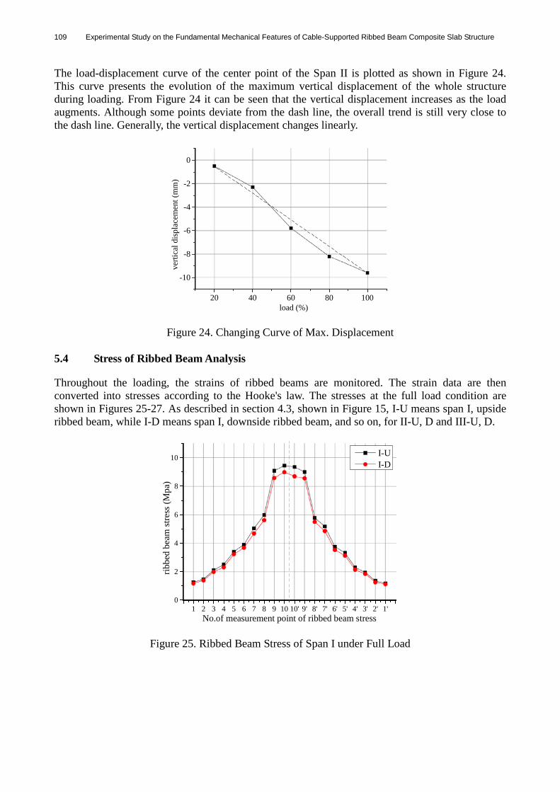
The load-displacement curve of the center point of the Span II is plotted as shown in Figure 24. This curve presents the evolution of the maximum vertical displacement of the whole structure during loading. From Figure 24 it can be seen that the vertical displacement increases as the load augments. Although some points deviate from the dash line, the overall trend is still very close to the dash line. Generally, the vertical displacement changes linearly.
20 40 60 80 100
-10
-8
-6
-4
-2
0ve
rtica
l dis
plac
emen
t(m
m)
load (%)
Figure 24. Changing Curve of Max. Displacement
5.4 Stress of Ribbed Beam Analysis Throughout the loading, the strains of ribbed beams are monitored. The strain data are then converted into stresses according to the Hooke's law. The stresses at the full load condition are shown in Figures 25-27. As described in section 4.3, shown in Figure 15, I-U means span I, upside ribbed beam, while I-D means span I, downside ribbed beam, and so on, for II-U, D and III-U, D.
1 2 3 4 5 6 7 8 9 10 10' 9' 8' 7' 6' 5' 4' 3' 2' 1'0
2
4
6
8
10
ribbe
d be
am st
ress
(Mpa
)
No.of measurement point of ribbed beam stress
I-UI-D
Figure 25. Ribbed Beam Stress of Span I under Full Load
Wentao Qiao, Qi An, Mingshan Zhao and Dong Wang 110
1 2 3 4 5 6 7 8 9 10 10' 9' 8' 7' 6' 5' 4' 3' 2' 1'0
2
4
6
8
10
ribbe
d be
am st
ress
(Mpa
)
No.of measurement point of ribbed beam stress
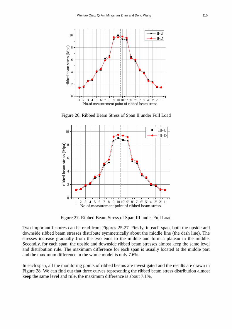
II-UII-D
Figure 26. Ribbed Beam Stress of Span II under Full Load
1 2 3 4 5 6 7 8 9 10 10' 9' 8' 7' 6' 5' 4' 3' 2' 1'0
2
4
6
8
10
ribbe
d be
am st
ress
(Mpa
)
No.of measurement point of ribbed beam stress
III-UIII-D
Figure 27. Ribbed Beam Stress of Span III under Full Load
Two important features can be read from Figures 25-27. Firstly, in each span, both the upside and downside ribbed beam stresses distribute symmetrically about the middle line (the dash line). The stresses increase gradually from the two ends to the middle and form a plateau in the middle. Secondly, for each span, the upside and downside ribbed beam stresses almost keep the same level and distribution rule. The maximum difference for each span is usually located at the middle part and the maximum difference in the whole model is only 7.6%. In each span, all the monitoring points of ribbed beams are investigated and the results are drawn in Figure 28. We can find out that three curves representing the ribbed beam stress distribution almost keep the same level and rule, the maximum difference is about 7.1%.

111 Experimental Study on the Fundamental Mechanical Features of Cable-Supported Ribbed Beam Composite Slab Structure
U2 U4 U6 U8 U10 U9' U7' U5' U3' U1' D2 D4 D6 D8 D10 D9' D7' D5' D3' D1'0
1
2
3
4
5
6
7
8
9
10
11
ribbe
d be
am st
ress
(Mpa
)
No.of measurement point of ribbed beam stress
Span I Span II Span III
Figure 28. Ribbed Beam Stresses of All the Three Spans under Full Load
The maximum stress location is at measurement point II-U10, which is taken to analyze the variation feature of the ribbed beam stress during the loading process. The relevant data are collected and shown in Figure 29. The stress increases as the load augments, although several points deviate from the dash line, they are all close to the dash line. In general, the ribbed beam stress changes linearly.
20 40 60 80 100
2
4
6
8
10
ribbe
d be
am st
ress
(Mpa
)
load (%) Figure 29. Changing Curve of Max. Stress of Ribbed Beam
5.5 Stress of Strut Analysis Similar to the ribbed beam stress analysis, the strains of the struts are monitored and converted to stresses as well, as shown in Figures 30-32. As described in section 4.3, shown in Figure 17, I-SL means span I, left limb strain monitoring point of V type strut; I-SR means span I, the right limb strain monitoring point, and so on for II-SL, SR and III-SL, SR. Note that all the stresses in the struts are compressive stress, as marked negative in the figures.

Wentao Qiao, Qi An, Mingshan Zhao and Dong Wang 112
1 2 3 4 5 5' 4' 3' 2' 1'-23
-22
-21
-20
-19
-18
-17
-16
-15
stru
t stre
ss(M
pa)
No.of strut
I-SLI-SR
Figure 30. Strut Stress of Span I under Full Load
1 2 3 4 5 5' 4' 3' 2' 1'
-25
-24
-23
-22
-21
-20
-19
-18
stru
t stre
ss(M
pa)
No.of sturt
II-SLII-SR
Figure 31. Strut Stress of Span II under Full Load
1 2 3 4 5 5' 4' 3' 2' 1'
-23
-22
-21
-20
-19
-18
-17
-16
stru
t stre
ss(M
pa)
No.of sturt
III-SLIII-SR
Figure 32. Strut Stress of Span III under Full Load
113 Experimental Study on the Fundamental Mechanical Features of Cable-Supported Ribbed Beam Composite Slab Structure
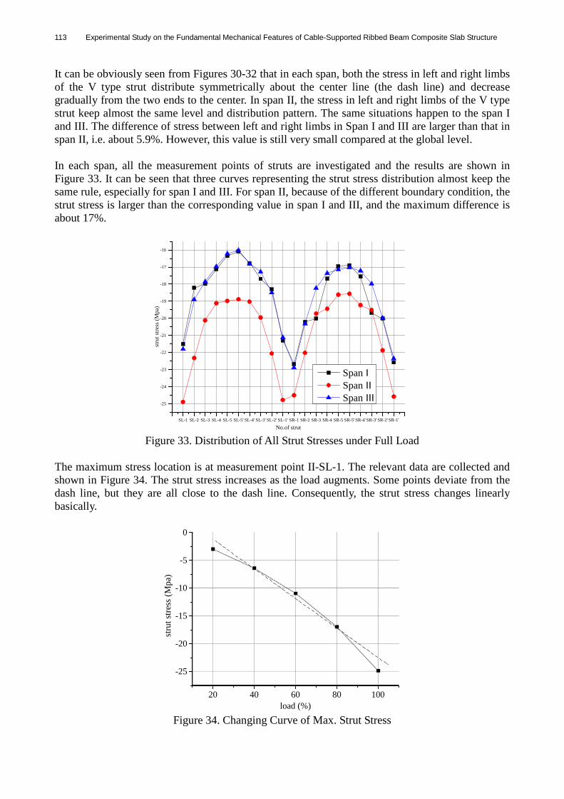
It can be obviously seen from Figures 30-32 that in each span, both the stress in left and right limbs of the V type strut distribute symmetrically about the center line (the dash line) and decrease gradually from the two ends to the center. In span II, the stress in left and right limbs of the V type strut keep almost the same level and distribution pattern. The same situations happen to the span I and III. The difference of stress between left and right limbs in Span I and III are larger than that in span II, i.e. about 5.9%. However, this value is still very small compared at the global level. In each span, all the measurement points of struts are investigated and the results are shown in Figure 33. It can be seen that three curves representing the strut stress distribution almost keep the same rule, especially for span I and III. For span II, because of the different boundary condition, the strut stress is larger than the corresponding value in span I and III, and the maximum difference is about 17%.
SL-1 SL-2 SL-3 SL-4 SL-5 SL-5' SL-4' SL-3' SL-2' SL-1' SR-1 SR-2 SR-3 SR-4 SR-5 SR-5' SR-4' SR-3' SR-2' SR-1'
-25
-24
-23
-22
-21
-20
-19
-18
-17
-16
stru
t stre
ss (M
pa)
No.of strut
Span I Span II Span III
Figure 33. Distribution of All Strut Stresses under Full Load
The maximum stress location is at measurement point II-SL-1. The relevant data are collected and shown in Figure 34. The strut stress increases as the load augments. Some points deviate from the dash line, but they are all close to the dash line. Consequently, the strut stress changes linearly basically.
20 40 60 80 100
-25
-20
-15
-10
-5
0
stru
t stre
ss(M
pa)
load (%) Figure 34. Changing Curve of Max. Strut Stress

Wentao Qiao, Qi An, Mingshan Zhao and Dong Wang 114
5.6 Effect of Temperature The action of temperature on CBS structure was studied in this experiment as well. It was spring season and the temperature was about 15℃ when the model’s construction was finished, namely, the closure temperature of this test model is 15℃. In order to investigate the temperature action, the test model was kept through one whole year, the highest temperature is about 40℃ in the summer, and the lowest temperature is about -15℃ in the winter. Consequently, based on the closure temperature, the temperature difference varies from -30℃ to 25℃. In the experiment, the temperature of all the three spans was measured by thermometer, and the cable forces were selected to illustrate the action of temperature on the structure. The cable was divided into nine segments in each span, the number of which is shown in Figure 17. the cable force of each segment was measured by the same way used in section 4.3, and the data were collected and analyzed respectively at -15℃, -5℃, 5℃, 15℃, 20℃, 30℃, 40℃. The results were shown in Figs. 35-37. It can be seen that the changing rule of the cable force of each segment in all the three spans are similar, compared with the mechanical status at the closure temperature, namely 15℃. When the temperature goes up, the cable forces almost keep increasing, but keep reducing with the temperature going down. The maximum positive changing rate (when the temperature difference is 25℃ ) is about 12.9%, and the maximum negative changing rate (when the temperature difference is -30℃) is about -8.7%. In consequence, the action of the temperature on the CBS is not significant. The self-adjustable supports can release the internal constraint forces induced by the temperature effectively.
closure temp. 15℃
Figure 35. The Changing of SPAN I Cable Forces at Different Temperature
closure temp. 15℃
Figure 36. The Changing of SPAN II Cable Forces at Different Temperature

115 Experimental Study on the Fundamental Mechanical Features of Cable-Supported Ribbed Beam Composite Slab Structure
closure temp. 15℃
Figure 37. The Changing of SPAN III Cable Forces at Different Temperature
6. CONCLUSIONS In this paper, the fundamental mechanical characteristics were investigated though experimental study. Test results showed the feasibility and constructability of the CBS, and verified the predicted behavior by the theoretical analysis. The key conclusions are listed as follows. (1) During the loading process, all of the cable forces, vertical displacement, stresses of ribbed
beam and strut stresses approximately augment linearly with the increasing load. It indicates that although most of cable-supported structures are flexible and behave nonlinearly, if properly designed, it can achieve a high global rigidity and behave approximately linearly.
(2) CBS is usually designed symmetrically, in order to make all of the cable forces, structural
deformation, stresses of ribbed beam and strut stresses distribute symmetrically. For each span of CBS, the maximum vertical displacement is located in the mid-span area. The cable forces decrease gradually from the two ends to the middle, the minimum is located in the middle part. Similarly, the minimum strut stress is located in the middle. While the stresses of ribbed beam increase gradually from the two ends to the middle, the maximum is located in the middle.
(3) For each V type strut, the stress of left and right limbs are almost the same, the maximum
difference is only 5.9%. (4) The cable forces in different spans keep the same distribution rule. For span I and III, even the
values are very close. Although the corresponding cable forces in span II are larger because of the different boundary condition, the difference is still small on the whole. The same situations also happen in vertical displacement, stresses of ribbed beam and strut stresses. It indicates each span of CBS has the same mechanical features approximately, can be considered as an independent mechanical unit and represent the whole structure, which are in accordance with the theoretical calculation hypothesis.
(5) The temperature difference ranging from -30℃ to 25℃ was investigated, For the CBS, when
the temperature goes up, the cable forces almost keep increasing, but keep reducing with the temperature going down. When the temperature difference is 25℃, the maximum positive changing rate of the cable force is about 12.9%. When the temperature difference is -30℃, the maximum negative changing rate of the cable force is about 8.7%. The overall action of temperature on the CBS is not significant, since the self-adjustable supports release the internal constraint forces induced by the temperature effectively.

Wentao Qiao, Qi An, Mingshan Zhao and Dong Wang 116
ACKNOWLEDGEMENTS This work is sponsored by the National Natural Science Foundation of China (No.51208317), and Hebei Province Natural Science Fund (No.E2016210052). Special acknowledgement is also given to China Scholar Council for supporting this research in MIT, and to Prof. Nader Tehrani for his invitation and generous helps to me. REFERENCES [1] Qiao, W.T., “Study of Cable-supported Structure System”, PhD Dissertation. Tianjin: Tianjin
University, 2010. [in Chinese] [2] Xue, S.D., Gao, Z.Y. and Li, X.Y., “Research Status and Prospects of Cable Domes”,
Applied Mechanics and Materials, 2011, Vols. 94-96, pp. 1424-32. [3] Zhan, W.D. and Dong, S.L., “Advances in Cable Domes”, Journal of Zhejiang University,
2004, Vol. 38, No. 10, pp. 1298-1307. [4] Masao, S. and Kurasiro, T., “A Study on Structural Behaviors of Beam String Structure”,
Summaries of Technical Papers of Annual Meeting Architectural Institute of Japan, Tokyo, Japan, 1985, Vol. B1, pp. 280–284.
[5] Masao, S., “A Study on Structural Planning of Radial Type Beam String Structures”, Summaries of Technical Papers of Annual Meeting Architectural Institute of Japan, Tokyo, Japan, 1988, Vol. B1, pp. 1365–1366.
[6] Masao, S. and Ohtake, T., “A Study on Beam String Structure with Flat Circular Arch”, Summaries of Technical Papers of Annual Meeting Architectural Institute of Japan, Tokyo, Japan, 1988, Vol. B1, pp. 1369–1374.
[7] Masao, S. and Okasa, A., “The Role of String in Hybrid String Structure”, Engineering Structures 1999, Vol. 21, No. 8, pp. 756–69.
[8] Kawaguchi, M., Abe, M. and Hatato, T., et al., “On a Structure System "Suspen-dome"”, Proc. of IASS Symposium, Istanbul, 1993, pp. 523-530.
[9] Kawaguchi, M., Abe, M. and Tatemichi, I., “Design, Tests and Realization of "Suspen-dome" System”, Journal of the IASS, 1999, Vol. 40, No. 131, pp. 179-192.
[10] Chen, Z.H. and Qiao, W.T., “A New-style Cable Supported Structure System-Cable Supported Barrel Vault Structure System”, Proc. of APCS2009, Nogoya, 2009, pp. 69-79.
[11] Chen, Z.H., Qiao, W.T. and Yan, X.Y., “Cable Supported Barrel Vault Structure System and Research on Mechanics Characteristics”, International Journal of Advanced Steel Construction, 2010, Vol. 6, No. 3, pp. 867-878.
[12] Qiao, W.T. and Chen, Z.H., “Scale model test research on cable supported barrel vault structure”, Advanced Materials Research, 2011, Vols. 163-167, pp. 465-470.
[13] Qiao, W.T., Chen, Z.H. and Zhao, M.S., “Test study on basic static characteristics of cable supported barrel vault structure”, International Journal of Advanced Steel Construction, 2012, Vol. 8, No. 2, pp. 199-211.
[14] Chen, Z.H. and Qiao, W.T., “Analysis on Cable Supported Concrete Roof Structure and its Basic Characteristics”, Building Structure, 2010, Vol. 40, No. 11, pp. 22-25. [in Chinese]
[15] Qiao, W.T., Li, Y. and Deng, Y.Z., “Research on Mechanical features of Cable-supported Ribbed Beam Composite Slab Structure”, Proc. of the 14th Conference on Modern Structural Engineering, Tianjin, China, 2014, pp. 328-332. [in Chinese]
[16] Liu, Y.P. and Chan, S.L., “Second-order Analysis for Design of Glass-supporting and Pre-tensioned Trusses”, International Journal of Structural Stability and Dynamics, 2009, Vol. 9, No. 3, pp. 489-510.
[17] Li, Z.X., “Theory and Technique of Engineering Structure Experiments”, TianJin: Tianjin University Press, 2004. [in Chinese]
[18] “GB5009-2012: Load Code for the Design of Building Structures”, Beijing: China Building Industry Press, 2012. [in Chinese]