experiments of blast furnace slag as a mud cake … · experiments of blast furnace slag as a mud...
TRANSCRIPT
Send Orders for Reprints to [email protected]
The Open Petroleum Engineering Journal, 2014, 7, 1-9 1
1874-8341/14 2014 Bentham Open
Open Access
Experiments of Blast Furnace Slag as a Mud Cake Modifier and Its Trial in Horizontal Well I306H
Jun Gu1,*
, Jibiao He1, Baoliang Sun
2, Mingfu Kou
2, Wenping Zhang
1 and Su Zhang
1
1Petroleum Engineering Department, Faculty of Earth Resources, China University of Geosciences, Wuhan, 430074,
China; 2Yumen Oilfield Branch, PetroChina, Jiuquan 735000, China
Abstract: Blast furnace slag (BFS) was added into drilling fluid as a mud cake modifier (MCM) for the reuse of BFS.
The effects of MCM on drilling fluid rheology and shear strength of cement- formation interface (SSCFI) were evaluated.
The experimental results showed that the optimized formula of the drilling fluid has 1.0 wt% MCM. The simulation re-
sults showed that SSCFI increased significantly with the addition of MCM. Based on the mechanism analysis of BFS as
an MCM to improve SSCFI, it is found that the transformation of mud cake to agglomerated cake (MTA) can be the main
reason. The trial result of horizontal well I306H in Laojunmiao oilfield in China showed that the one-time success rate of
cementing operation was 100% and the high quality rate was 79.78%. This horizontal well is flowing well after perfora-
tion with oil production of 11.5t/d and the water cut is only 9%. Compared to the adjacent horizontal wells after fractur-
ing, the oil production rate is increased by 228.57%-259.38%. Obviously, the effect of BFS as an MCM is self-evident.
Meanwhile, this research provides a new way for the recycling of BFS.
Keywords: Blast furnace slag, mud cake modifier, drilling fluid property, SSCFI, horizontal well.
1. INTRODUCTION
Blast furnace slag (BFS) is a kind of residue from steel plants. The emission of BFS from steel plants is 70 million tons every year in China while only 38.7% of it is utilized. At present, BFS powder is mainly applied to civil engineer-ing
[1-8]. Thus, BFS as a mud cake modifier (MCM) for well
cementing of oil and gas wells is a breakthrough on the recy-cle of BFS.
The technical problems of annular isolation are centered on interlayer channeling after well cementing of oil and gas wells [9]. Because the mud cake between the cement paste and formation decreases the shear strength of cement-formation interface (SSCFI) [10, 11], a method of mud to cement (MTC) emerged in the early 1990s [12]. By combin-ing the MTC method and multifunctional drilling fluids, the integrated solidification and cementation of cement-formation interface were achieved, and SSCFI was im-proved. However, the MTC solidified body was liable to serious embrittlement. So the MTC method can only be used in the well cementing of surface casing and intermediate casing, as the MTC solidified body does not have the solidified performance of traditional oil well cement [13].
Based on this, the new method of mud cake to agglomer-ated cake (MTA) to improve the isolation quality of cement-formation interface was proposed [14]. In this new method, the cement slurry system is not changed. The evidences of the integrated solidification and cementation of cement-formation interface with MTA method were obtained [15, 16], the kinetic models of ISC with MTA method were
*Address correspondence to this author at the No. 388, Lumo Road, Wuhan,
China. Postcard: 430074; Tel: +86 27 6784 8569;
E-mail: [email protected]
established [17] and the synergism of MCM with the form-ing agent of agglomerated cake [18] was studied [19]. The application effects of six oilfields in China showed that the MTA method improves significantly the qualified rate and high quality rate of well cementing [20, 21]. But, this method is not used in horizontal well. Based on the drilling fluid and cement slurry from Laojunmiao oilfield in China, the effects of BFS as an MCM on the drilling fluid rheology were investigated. The relationship of SSCFI with the addi-tion of MCM and curing time was evaluated. The mecha-nism of BFS as an MCM to improve SSCFI was analyzed. The trial effect of horizontal well I306H was introduced in Laojunmiao oilfield in China.
2. MATERIALS
BFS is from Shengda Material Co., Ltd., Wuhan, China. The specific surface area is 0.472 m
2/g, the surface average
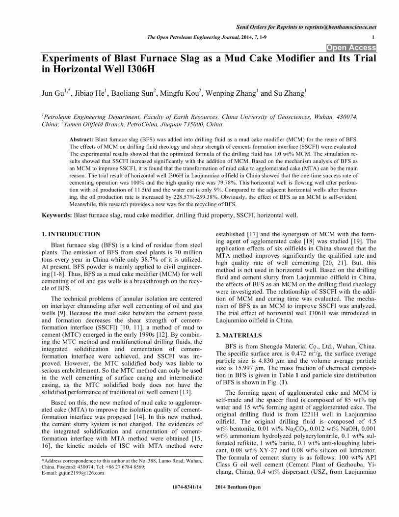
particle size is 4.830 μm and the volume average particle size is 15.997 μm. The mass fraction of chemical composi-tion in BFS is given in Table 1 and particle size distribution of BFS is shown in Fig. (1).
The forming agent of agglomerated cake and MCM is self-made and the spacer fluid is composed of 85 wt% tap water and 15 wt% forming agent of agglomerated cake. The original drilling fluid is from I221H well in Laojunmiao oilfield. The original drilling fluid is composed of 4.5 wt% bentonite, 0.01 wt% Na2CO3, 0.012 wt% NaOH, 0.001 wt% ammonium hydrolyzed polyacrylonitrile, 0.1 wt% sul-fonated refikite, 1 wt% barite, 0.1 wt% anti-sloughing lubri-cant, 0.08 wt% XY-27 and 0.08 wt% silicon oil lubricator. The formula of cement slurry is as follows: 100 wt% API Class G oil well cement (Cement Plant of Gezhouba, Yi-chang, China), 0.4 wt% dispersant (USZ, from Laojunmiao
2 The Open Petroleum Engineering Journal, 2014, Volume 7 Gu et al.
Table 1. Mass Fraction of Chemical Composition in BFS
Mass fraction SiO2 CaO Fe2O3 Al2O3 MgO LOI
BFS /% 32.79 36.69 0.84 5.78 9.29 0.82
oilfield), 2.5 wt% filtrate reducer (M53S, from Laojunmiao oilfield) and 44 wt% tap water.
Fig. (1). Particle size distribution of BFS.
3. METHODS
3.1. Drilling Fluid Rheology
3.1.1. Experimental Condition
The curing time is 0, 2, 4, 8, 10 and 12 days, respec-tively, the curing temperature is 50 °C and the curing pres-sure is 0.1 MPa. The addition of MCM is set as 0 (e.g. origi-nal drilling fluid), 1.0 wt%, 1.2 wt%, 1.3 wt%, 1.4 wt% and 1.5 wt%.
3.1.2. Experimental Step
The experimental procedure of drilling fluid rheology is given in five steps as follows:
(1) Weigh drilling fluid and MCM with ACS-30 electronic price scale (Huaying Hengqi Co., Ltd., Yongkang,
China) according to the formula.
(2) Pour the drilling fluid into the pulp cup of JB-12K two-axis high-speed agitator (Hisense optical communication Co., Ltd., Qingdao, China), and stir it at 3,000 rpm. Then, add MCM and stir it for 5 min at 12,000 rpm until MCM
are almost dissolved in the drilling fluid. Measure and re-cord readings on the dial disc at 600, 300 and 3 rpm with ZNN-D6 six-speed viscometer (Hisense optical commu-nication Co., Ltd., Qingdao, China).
(3) Stir this drilling fluid for 20 min at 12, 000 rpm. Then
pour the drilling fluid into high temperature aging tank and roll it for 48 h at 50 °C in GRL-BX portable roller heating furnace (Hisense optical communication Co., Ltd., Qingdao, China).
(4) Pour the drilling fluid from the aging tank into the pulp cup and stir it for 5 min at 12,000 rpm. Then, measure
and record the readings on the dial disc at 600, 300 and 3 rpm.
(5) Repeat the steps (3) and (4) to get the readings of 4, 8, 10 and 12 days.
3.2. SSCFI
3.2.1. Experimental Condition
The curing time of experimental samples is 2, 15 and 30 days, the curing temperature is 50 °C in water and the curing pressure is 0.1 MPa. The thickness of mud cake in Laojun-miao oilfield ranges mostly from 0.5 to 1.0 mm. Therefore, the thickness of mud cake is set as 0.5 and 1.0 mm respec-tively. The addition of MCM is 0 (e.g. original drilling fluid), 0.7, 1.0 and 1.2 wt%, respectively. The permeability and porosity of simulated wellbores (SWB) [22] are 24 10
-3 μm
2 and 17.8%, respectively, which simulate the
main isolation section in Laojunmiao oilfield. The outside diameter and inside diameter of SWB are 10 cm and 3.3 cm, respectively. The height of SWB is set to be 5.5 cm in the experiment.
3.2.2. Experimental Procedure
A simulated experimental system is built independently. The system includes the preparation of SWB, formation of simulated mud cake, injection of oil well cement slurry, cur-ing of experimental sample and test of shear force at cement-formation interface.
(1) Preparation of SWB. In order to simulate the physical properties and compaction law of interlayer, SWB is pre-pared as follows:
• Determine the proportion of relevant materials and the constant pressure required through a number of simulated experiments.
• Screen the yellow sand and normal sand with a certain grain size for SWB.
• Weigh materials in accordance with the partitioning de-termined above, stir uniformly and then get the mixed materials for SWB.
• Assemble and locate the polyvinyl chloride (PVC) pipe mould.
• Set PVC pipe mould on the frame of the pressure testing machine, and add the uniformly mixed materials into it.
• Press the surface of the mixed materials slowly to a con-stant pressure with a steely cylindrical indenter, and maintain the pressure for 3 to 5 minutes.
• Release the pressure, and take out the PVC pipe mould and SWB together.
• Leave it aside for 24 hours in air, and then put it in the furnace box and heat it. The PVC pipe will swell and
0.1 1 10 100 1000
6
5
4
3
2
1
0
Particle Size /μm
100
80
60
40
20
0
Vol
ume
/%
Experiments of Blast Furnace Slag as a Mud Cake Modifier The Open Petroleum Engineering Journal, 2014, Volume 7 3
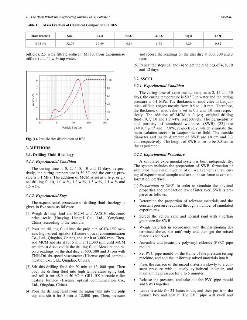
peel off from SWB after being heated. Thus, an entire SWB is obtained (Fig. (2)).
Fig. (2). SWB based on physical properties and compaction law of
interlayer.
In this experiment, the height of SWB is set to be 5.5 cm,
which simulates the thickness of wellbore (h). While the inside diameter of SWB is set to be 3.3 cm, which simulates the borehole size (D).
(2) Formation of simulated mud cake. The formation method of simulated mud cake is described as follows:
• Put SWB on a glass plate or a smooth board and seal the interface between SWB and the glass plate with tempera-ture butter.
• Inject the drilling fluid along the axial direction of SWB uniformly with a large injector until the volume of SWB is filled.
• Maintain it in a curing box for 2 to 12 hours under the required temperature, and then form a mud cake of cer-tain thickness. Remove the false and redundant mud cake with glass rods gradually, and then measure the thickness of the mud cake in borehole wall with ruler. Repeat this process until getting the desired thickness of the mud cake (from 0 to 5 mm).
(3) Injection of oil-well cement slurry. The cement slurry is prepared and filled into SWB as follows:
• Prepare the cement slurry according to API RP 10B. Then inject it into the SWB that is immersed by spacer.
• Stir the cement slurry several times with a stirrer bar to ensure that the cement slurry has a good consistency.
(4) Curing of experimental sample. The curing method of experimental sample is as follows:
• Use special water proofing methods to process the sam-ples that are injected with the cement slurry.
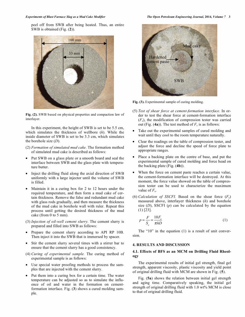
• Put them into a curing box for a certain time. The water temperature can be adjusted so as to simulate the influ-ence of oil and water in the formation on cement-formation interface. Fig. (3) shows a cured molding sam-ple.
Fig. (3). Experimental sample of curing molding.
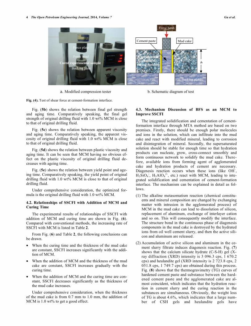
(5) Test of shear force at cement-formation interface. In or-der to test the shear force at cement-formation interface
(Fs), the modification of compression tester was carried
out (Fig. (4a)). The test method of Fs is as follows:
• Take out the experimental samples of cured molding and wait until they cool to the room temperature naturally.
• Clear the readings on the table of compression tester, and adjust the force and decline the speed of force plate to appropriate ranges.
• Place a backing plate on the centre of base, and put the
experimental sample of cured molding and force head on the backing plate (Fig. (4b)).
• When the force on cement paste reaches a certain value,
the cement-formation interface will be destroyed. At this moment, the force value showed on the table of compres-
sion tester can be used to characterize the maximum
value of Fs.
(6) Calculation of SSCFI. Based on the shear force (Fs) measured above, interlayer thickness (h) and borehole size (D), SSCFI (p) can be calculated by the equation (1) [23].
p =F
Sc
=10F
s
hD (1)
The “10” in the equation (1) is a result of unit conver-sion.
4. RESULTS AND DISCUSSION
4.1. Effects of BFS as an MCM on Drilling Fluid Rheol-
ogy
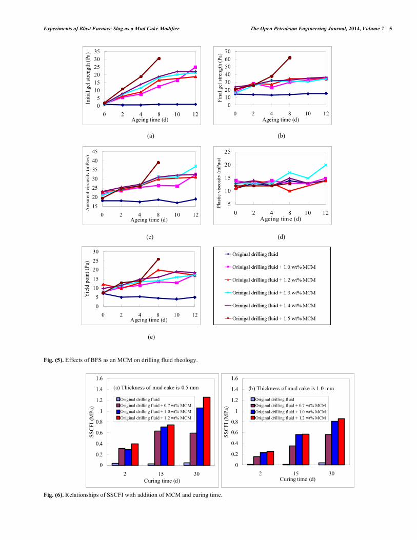
The experimental results of initial gel strength, final gel strength, apparent viscosity, plastic viscosity and yield point
of original drilling fluid with MCM are shown in Fig. (5).
Fig. (5a) shows the relation between initial gel strength
and aging time. Comparatively speaking, the initial gel
strength of original drilling fluid with 1.0 wt% MCM is close to that of original drilling fluid.
33 mm
100 mm
SWB
Mud cake
Hardened cement paste
4 The Open Petroleum Engineering Journal, 2014, Volume 7 Gu et al.
Fig. (4). Test of shear force at cement-formation interface.
Fig. (5b) shows the relation between final gel strength
and aging time. Comparatively speaking, the final gel strength of original drilling fluid with 1.0 wt% MCM is close to that of original drilling fluid.
Fig. (5c) shows the relation between apparent viscosity and aging time. Comparatively speaking, the apparent vis-cosity of original drilling fluid with 1.0 wt% MCM is close to that of original drilling fluid.
Fig. (5d) shows the relation between plastic viscosity and aging time. It can be seen that MCM having no obvious ef-fect on the plastic viscosity of original drilling fluid de-creases with ageing time.
Fig. (5e) shows the relation between yield point and age-ing time. Comparatively speaking, the yield point of original drilling fluid with 1.0 wt% MCM is close to that of original drilling fluid.
Under comprehensive consideration, the optimized for-mula is the original drilling fluid with 1.0 wt% MCM.
4.2. Relationships of SSCFI with Addition of MCM and Curing Time
The experimental results of relationships of SSCFI with addition of MCM and curing time are shown in Fig. (6). Compared with conventional methods, the increasing rate of SSCFI with MCM is listed in Table 2.
From Fig. (6) and Table 2, the following conclusions can be drawn.
• When the curing time and the thickness of the mud cake are constant, SSCFI increases significantly with the addi-tion of MCM.
• When the addition of MCM and the thickness of the mud cake are constant, SSCFI increases gradually with the curing time.
• When the addition of MCM and the curing time are con-stant, SSCFI decreases significantly as the thickness of the mud cake increases.
Under comprehensive consideration, when the thickness of the mud cake is from 0.7 mm to 1.0 mm, the addition of MCM is 1.0 wt% to get a good effect.
4.3. Mechanism Discussion of BFS as an MCM to
Improve SSCFI
The integrated solidification and cementation of cement-formation interface through MTA method are based on two premises. Firstly, there should be enough polar molecules and ions in the solution, which can infiltrate into the mud cake and react with modified mineral, leading to corrosion and disintegration of mineral. Secondly, the supersaturated solution should be stable for enough time so that hydration products can nucleate, grow, cross-connect smoothly and form continuous network to solidify the mud cake. There-fore, available ions from forming agent of agglomerated cake and hydration products of cement are necessary. Diagenesis reaction occurs when these ions (like OH
-,
H3SiO4-, H3AlO4
2-, etc.) react with MCM, leading to inte-
grated solidification and cementation of cement-formation interface. The mechanism can be explained in detail as fol-lows.
(1) The alkaline metasomatism reaction (chemical constitu-ents and mineral composition are changed by exchanging matter with intrusion in the agglomerated process) of MCM in the mud cake can lead to dissolution of silicon, replacement of aluminum, exchange of interlayer cation and so on. This will consequently modify the interface. The structure bond in the continuous phase of diagenesis components in the mud cake is destroyed by the hydrated ions from oil well cement slurry, and then the active sili-con and aluminum are released.
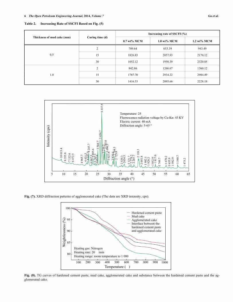
(2) Accumulation of active silicon and aluminum in the ce-ment slurry filtrate induces diagenesis reaction. Fig. (7) shows that the calcium silicate hydrate (C-S-H) gel (X-ray diffraction (XRD) intensity is 3 096.3 cps, 1 670.2 cps) and heulandite gel (XRD intensity is 2 723.8 cps, 2 051.8 cps, 1 749.7 cps) are obtained during this process. Fig. (8) shows that the thermogravimetry (TG) curves of hardened cement paste and substance between the hard-ened cement paste and the agglomerated cake are al-most coincident, which indicates that the hydration reac-tion in cement slurry and the curing reaction in the substances are simultaneous. Obviously, the weight loss of TG is about 4.6%, which indicates that a large num-ber of CSH gels and heulandite gels have
a. Modified compression tester b. Schematic diagram of test
Backing plate
Experimental sample of
curing molding
Force head
Mud cake Cement paste
hBacking plate
Cured experimental sample
Force head
Force plate
Experiments of Blast Furnace Slag as a Mud Cake Modifier The Open Petroleum Engineering Journal, 2014, Volume 7 5
Fig. (5). Effects of BFS as an MCM on drilling fluid rheology.
Fig. (6). Relationships of SSCFI with addition of MCM and curing time.
05
101520253035
0 2 4 8 10 12Ageing time (d)
Initi
al g
el s
tren
gth
(Pa)
010203040506070
0 2 4 8 10 12Ageing time (d)
Fin
al g
el s
tren
gth
(Pa)
15
20
25
30
35
40
45
0 2 4 8 10 12Ageing time (d)
5
10
15
20
25
0 2 4 8 10 12Ageing time (d)
0
5
10
15
20
25
30
0 2 4 8 10 12Ageing time (d)
Yie
ld p
oint
(P
a)
(c) (d)
(e)
(a) (b)
App
aren
t vis
cosi
ty (
mP
a▪s)
Pla
stic
vis
cosi
ty (
mP
a▪s)
(a) Thickness of mud cake is 0.5 mm
0
0.2
0.4
0.6
0.8
1
1.2
1.4
1.6
2 15 30Curing time (d)
SS
CF
I (M
Pa)
Original drilling fluid Original drilling fluid + 0.7 wt% MCMOriginal drilling fluid + 1.0 wt% MCM
Original drilling fluid + 1.2 wt% MCM
(b) Thickness of mud cake is 1.0 mm
0
0.2
0.4
0.6
0.8
1
1.2
1.4
1.6
2 15 30Curing time (d)
SS
CF
I (M
Pa)
Original drilling fluid Original drilling fluid + 0.7 wt% MCM
Original drilling fluid + 1.0 wt% MCMOriginal drilling fluid + 1.2 wt% MCM
6 The Open Petroleum Engineering Journal, 2014, Volume 7 Gu et al.
Table 2. Increasing Rate of SSCFI Based on Fig. (5)
Increasing rate of SSCFI (%)
Thickness of mud cake (mm) Curing time (d)
0.7 wt% MCM 1.0 wt% MCM 1.2 wt% MCM
2 709.64 653.39 943.49
15 1826.83 2057.93 2170.12 0.5
30 1052.12 1950.39 2320.85
2 842.86 1266.67 1360.12
15 1787.70 2934.22 2984.49 1.0
30 1416.53 2095.66 2228.18
Fig. (7). XRD diffraction patterns of agglomerated cake (The data are XRD intensity, cps).
Fig. (8). TG curves of hardened cement paste, mud cake, agglomerated cake and substance between the hardened cement paste and the ag-
glomerated cake.
10 0
13.4
8
355.
8
7 13
2.4
6 47
2.5
4 96
5.7
4 43
1.5
4 24
5.7
3 88
5.6
3 76
7.3
365
7.6
3 56
8.7
3 33
7.5
3 43
4.7
3 23
6.2
3 18
5.0
3 09
6.3
3 02
7.6
2 83
0.4
2 78
4.5
2 72
3.8
2 52
9.3
2454
.5
2 32
1.7
2 27
9.2
2 20
7.7 2 11
8.3
2 05
1.8
1 98
2.1
1 85
2.9
1 92
8.2
1 81
7.0
1 74
9.7
1 67
0.2
1 63
5.9
1 54
0.7
1 47
3.2 4 33
7.5
Inte
nsit
y (c
ps)
Diffraction angle (°) 10 5 15 20 25 30 35 40 45 50 55 60 65
Temperature: 25 � Fluorescence radiation voltage by Cu-Kα: 45 KV Electric current: 40 mA Diffraction angle: 5-65 °
4 06
2.3
1 59
2.9
100 200 300 400 500 600 700 800 900 1000
100
95
90
85
80
Temperature (�)
Heating gas: Nitrogen Heating rate: 20 �/min Heating range: room temperature to 1 000 �
Wei
ghtle
ssne
ss (
%)
— Hardened cement paste— Mud cake — Agglomerated cake — Interface between the
hardened cement paste and agglomerated cake
Experiments of Blast Furnace Slag as a Mud Cake Modifier The Open Petroleum Engineering Journal, 2014, Volume 7 7
been formed. Transformation process of the mud cake to the agglomerated cake includes inducing reaction, sur-face micro-crystallization and interface coupling. Firstly, the energy state of a metastable compound is induced by alkaline ions from oil well cement slurry filtrate, leading to the decrease in reaction barrier. OH
-, Ca
2+ and
SO42-
ions play an important part in this reaction. Sec-ondly, the hydration products in gel precipitate more quickly when the metastable compounds exist as micro-crystal nucleus, which accelerates this transformation process. Finally, the mud cake turns into a stable ag-glomerated cake by inducing reaction, hydration process and hardening process. The microscopic gel structure of the agglomerated cake is closely related to its macro-scopic physical properties.
(3) The pore aqueous solution of the structure of agglomer-ated cake is rich in elements such as S, Mg, Fe, Ca and Si. When these elements accumulate to a certain concen-tration with the consumption of free water at the later hydration stage of oil well cement, these ions combine and form some new complexes. These complexes are filled into original pore space. Simultaneously, the gels and MCM particles with 10 μm in size that is distributed homogeneously in the agglomerated cake are filled into the capillary pores together, thus im-proving the pore structure of the agglomerated cake. At the same time, other particles play a framework role in
the agglomerated cake, whose structure is similar to con-crete aggregate. It will improve the cementation perform-ance and enhance the microstructure of the agglomerated cake. As a result, the hardened cement paste and the agglomerated cake are cemented together. Thus, SSCFI increases significantly.
5. FIELD TRIAL
5.1. Horizontal Well I306H
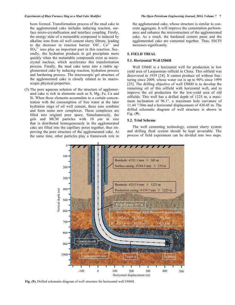
Well I306H is a horizontal well for production in low yield area of Laojunmiao oilfield in China. This oilfield was discovered in 1939 [24]. It cannot produce oil without frac-turing since 2009, whose water cut is up to 90% since 1999 [25]. The drilling objective of well I306H is to develop the remaining oil of this oilfield with horizontal well, and to improve the oil production for the low-yield area of old oilfields. This well has a drilled depth of 1225 m, a maxi-mum inclination of 96.1°, a maximum hole curvature of 11.44 °/30m and a horizontal displacement of 430.45 m. The drilled schematic diagram of well structure is shown in Fig. (9).
5.2. Trial Scheme
The well cementing technology, cement slurry system and drilling fluid system should be kept invariable. The process of field experiment can be divided into two steps.
Fig. (9). Drilled schematic diagram of well structure for horizontal well I306H.
Borehole:φ311.1 mm × 365 m
Surface casing:φ244.5 mm × 339 m
Borehole:φ215.9 mm × 1225 m
Production casing:φ139.7 mm × 1223 m
Kickoff point: 597 m
0 400100 200 300 500 -100
1000
300
600
800
400
700
500
900
200
100
0
Well depth Vertical depth Horizontal displacement
A 982.6 m 877.3 m 189.5 m
B 1217.9 m 897.0 m 423.4 m
Horizontal displacement (m)
Target A Target B
Cement sheath
Ver
tica
l dep
th (
m)
Agglomerated cake
8 The Open Petroleum Engineering Journal, 2014, Volume 7 Gu et al.
Table 3. Effects of MCM on Drilling Fluid Rheology from Horizontal Well I306H
Depth (m) Addition of
barite (t)
Addition of
MCM (t)
Drilling fluid density
(g/cm3)
Marsh funnel
viscosity (s)
Water loss
(ml)
Thickness of mud
cake (mm) pH value
570 0 0 1.16 40 8 0.5 10
590 0 0.6 1.21 37 6 0.5 10
610 0 0.25 1.20 43 6 0.5 10
740 0 0 1.20 48 6 0.5 10
760 19 0 1.45 77 8 1.0 9
789 0 0.35 1.43 88 7 1.0 9
900-1225 0 0.3 1.34 60 6 1.0 9
Table 4. Effect Comparison of Trial Well and Adjacent Horizontal Wells [26]
Horizontal well High quality rate of well cementing (%) Oil production (t/d) Flowing or fracturing production
Trial well: I306H 79.78 11.5 Flowing
Adjacent well 1: Miao Ping-1 57.51 3.5 Fracturing
Adjacent well 2: Miao Ping-19 48.49 3.2 Fracturing
Firstly, 1.0 wt% MCM is added in the drilling fluid before the reservoir. Secondly, 4 m
3 spacer fluid is prepared, which
is made up of in-site water and 15.0 wt% forming agent of agglomerated cake. The formula of cement slurry is as fol-lows: 100 wt% API Class G oil well cement (Cement Plant of Gezhouba, Yichang, China), 0.4 wt% dispersant (USZ), 2.5 wt% filtrate reducer (M53S) and 44 wt% tap water.
5.3. Trial Effect
The trial effect of horizontal well I306H in Laojunmiao oilfield is given in Table 3 and Table 4. From Table 3, MCM has a little effect on drilling fluid rheology and matches the experimental results. So, the original drilling fluid with 1.0 wt% MCM can meet the requirements of drilling operation. From Table 4, the high quality rate of trial well with the MTA method is up to 79.78%, which is increased by 22.27-31.29 percent points compared to that of adjacent horizontal well with conventional methods. The production effect of trial well shows that BFS as an MCM realizes a good annu-lar isolation for horizontal well and can significantly im-prove the production benefit of high water-cut reservoir for the low-yield area of old oilfields.
6. CONCLUSIONS
BFS as an MCM influences the properties of drilling fluid on a certain degree, but it can meet the requirements of drilling operation when the addition of MCM is 1.0 wt%. The optimized formula for Laojunmiao oilfield in China is drilling fluid with 1.0 wt% MCM.
SSCFI increases significantly with the addition of MCM and curing time. Under the same condition, SSCFI increases with the addition amount of MCM. But with the increase in the thickness of mud cake, SSCFI decreases significantly.
The mechanism of BFS as an MCM to improve SSCFI is that the forming agent of agglomerated cake is used to mod-ify and dispose the mud cake interface and make it react with MCM, and finally to form tight agglomerated cake (e.g. MTA).
The trial result of horizontal well I306H showed that the original drilling fluid with 1.0 wt% MCM meets the re-quirements of drilling operation. The development effect of BFS as an MCM is better than the conventional methods.
The research results of this article not only expand the application range of BFS, but also are beneficial to the high efficient production of high water-cut reservoir for the low-yield area of old oilfields.
CONFLICT OF INTEREST
The author(s) confirm that this article content has no con-flicts of interest.
ACKNOWLEDGEMENT
This research is supported by the National Natural Sci-ence Foundation of China (Nos. 51174180 and 40972103).
LIST OF SYMBOLS
P = SSCFI, MPa
F = Force, kN
Sc = Area of cylindrical surface, cm2
Fs = Shear force at the cement-formation interface, kN. It mainly depends on the friction force of the mud cake at the cement-formation interface and can be meas-ured in laboratory
Experiments of Blast Furnace Slag as a Mud Cake Modifier The Open Petroleum Engineering Journal, 2014, Volume 7 9
h = Interlayer thickness, cm
D = Borehole diameter, cm
REFERENCES
[1] H.G. Smolczyk, “The e ect of chemistry of slag on the strength of blast furnace slags cements”, Zement–Kalk-Gibs, vol. 31, no. 6, pp.
294-296, 1978. [2] D.G. Mantel, “Investigation into hydraulic activity of five granu-
lated blast furnace slags with eight di erent portland cements”, ACI Materials Journal, vol. 91, no. 5, pp. 471-477, 1994.
[3] R. Cioffi, L. Maffuccib, L. Santoro, and P.F. Glasser, “Stabilization of chloro-organics using organophilic bentonite in a cement-blast
furnace slag matrix”, Waste Management, vol. 21, no. 7, pp. 651-660, 2001.
[4] A. Guerrero, and S. Goñi, “Efficiency of a blast furnace slag ce-ment for immobilizing simulated borate radioactive liquid waste”,
Waste Management, vol. 22, no. 7, pp. 8310-836, 2002. [5] P.K. Chang, and W.M. Hou, “A study on the hydration properties
of high performance slag concrete analyzed by SRA”, Cement and Concrete Research, vol. 33, no. 2, pp. 183-189, 2003.
[6] G.Y. Li, and X.H. Zhao, “Properties of concrete incorporating fly ash and ground granulated blast-furnace slag”, Cement and Con-
crete Research, vol. 25, no. 3, pp. 293-299, 2003. [7] S.C. Pal, A. Mukherjee, and S.R. Pathak, “Investigation of hydrau-
lic activity of ground granulated blast furnace slag in concrete”, Cement and Concrete Research, vol. 33, no. 9, pp. 1481-1486,
2003. [8] S.Y. Zhong, K. Ni, and J.M. Li, “Properties of mortars made by
uncalcined FGD gypsum-fly ash-ground granulated blast furnace slag composite binder”, Waste Management, vol. 32, no. 7, pp.
1468-1472, 2012. [9] J. Gu, P. Zhong, C. Shao, S.H. Bai, H.Zhang, and K. Li, “Effect of
interface defects on shear strength and fluid channeling at cement-interlayer interface”, Journal of Petroleum Science and Engineer-
ing, vol. 100, pp. 117-122, 2012. [10] H.K.J. Ladva, B. Craster, T.G.J. Jones, G. Goldsmith, and D. Scott,
“The cement-to-formation interface in zonal isolation”, Journal of Petroleum Technology, vol. 57, no. 8, pp. 41-42, 2005.
[11] J. Gu, W.H. Yang, W.Z. Qin, Y.G. Zhang, and Y.T. Gao, “Evalua-tion method for isolation ability of cement-formation interface”,
Acta Petrolei Sinica, vol. 29, no. 3, pp. 451-454, 2008. [12] R.H. Wang, L.L. Jiang, and Y.H. Bu, “Experimental study on hy-
dration mechanism of slag MTC”, Acta Petrolei Sinica, vol. 29, no. 2, pp. 442-446, 2008.
[13] Z.X. Xiao, Q.L. Zhao, X. Chen, and Z.Y. Fan, “The induced mechanism of crystal during hydrate of blast furnace slag”, Acta
Petrolei Sinica, vol. 19, no. 5, pp. 117-121, 1998.
[14] J. Gu, “Problem of the cement-formation interface and scientific
conception of mud cake to agglomerated cake”, Journal of Oil Gas and Technology, vol. 19, pp. 117-121, 2009.
[15] J. Gu, and W. Qin, “Experimental study on integrated solidification and cementation of cement-formation interface based on Mud Cake
to Agglomerated Cake (MTA) method”, Petroleum Exploration and Development, vol. 37, pp. 226-231, 2010.
[16] J. Gu, W. Yang, Y. Zhang, Y. Gao, X. Liu, and T. Li, “Association between tuff di agenesis and mud cake to agglomerated cake
(MTA) at cement-formation interface”, Journal of China Univer-sity of Petroleum (National Science Edition), vol. 35, no. 1, pp. 64-
68, 73, 2011. [17] J. Gu, P. Zhong, W. Qin, H. Liu, L. Dong, and Y. Yang, “Kinetic
models of integrated solidification and cementation of cement-formation interface with new method”, The Open Chemical Engi-
neering Journal, vol. 7, pp. 9-17, 2013. [18] J. Gu, “A forming agent of agglomerated cake and its preparation
method and Application”, China Patent No. ZL200810047343.8, 2010.
[19] J. Gu, B. Wang, J.B. He, Q.G. Wang, G.P. Wen, P.F. Lai, and W.J. Du, “Synergism of mud cake modifier with forming agent of ag-
glomerated cake at cement-formation interface with MTA method”, The Open Chemical Engineering Journal, vol. 7, pp. 18-23, 2013.
[20] J. Gu, Y. Yang, L. Dong, P. Zhong, and H. Zhang, “Technical principle of integrated solidification and cementation at cement-
formation interface with mud cake to agglomerated cake (MTA) method and its oilfield application”, Advanced Materials Research,
vol. 236-238, pp. 2864-2867, 2011. [21] J. Gu, X. Li, H. Liu, Y. Zhang, and Y. Gao, “Laboratory evaluation
and application of new materials based on mud cake to agglomer-ated cake (MTA) method”, Advanced Materials Research, vol.
148-149, pp. 449-452, 2011. [22] J. Gu, “A simulated wellbore and its preparation method”, China
Patent No. ZL200810047342.3, 2011. [23] J. Gu, B. Wang, and B.L. Yang, “The influences of interface miss-
ing and formation property on shearing strength at cement-formation interface”, Petroleum Science and Technology, vol. 29,
no. 6, pp. 633-639, 2011. [24] C.G. Wang, and W.D. Sun, Laojunmiao Oilfield Development,
Petroleum Industry Press: Beijing, pp. 1, 88-125, 1999. [25] Y.Q. Li, and X. Zhang, “An exploration on the causes of continu-
ous multi-years stable production in Yumen oilfield”, Journal of Xi'an Shiyou University, vol. 22, no. 3, pp. 55-59, 2013.
[26] L.Z. Hu, J.F. Lu, K.Y. Yang, Z.Q. Cao, and C.Y. Li, “Study on swelling reduction and stimulation technique for water-sensitive
reservoirs in the east low production area of Laojunmiao oilfield”, Special Oil & Gas Reservoirs, vol. 16, no. 4, pp. 90-93, 2009.
Received: December 03, 2013 Revised: December 18, 2013 Accepted: December 19, 2013
© Gu et al.; Licensee Bentham Open.
This is an open access article licensed under the terms of the Creative Commons Attribution Non-Commercial License (http://creativecommons.org/-
licenses/by-nc/3.0/) which permits unrestricted, non-commercial use, distribution and reproduction in any medium, provided the work is properly cited.