experiments on fibre reinforced concrete two-way...
TRANSCRIPT

FIBRE CONCRETE 2013 September 12–13, 2013, Prague, Czech Republic
_________________________________________________________________________
1
EXPERIMENTS ON FIBRE REINFORCED CONCRETE TWO-WAY SLABS
FALL David 1, REMPLING Rasmus 2, LUNDGREN Karin 3
Abstract In design of two-way slabs, the possibility to redistribute the load between the different loading directions is used in plastic design methods. The main aim of this study was to investigate how fibres affect the structural behaviour, e.g. possibility for redistribution, crack pattern and load-carrying capacity. This was experimenally investigated on simply supported two-way slabs, loaded with a point load. The octagonal slabs spanned 2.2 m in both directions, and the reinforcement amount was twice as large in one direction as in the other. Three slabs of each reinforcement configuration was tested: conventionally reinforced, steel fibre reinforced and a combination of both types. A moderate fibre content (Vf=0.45%) of double hook-end steel fibres was used. The steel fibres affected the structural behaviour by providing post cracking ductility and increasing the ultimate load-carrying capacity. Fibres also affected the load distribution so that more load could be transferred in the weaker direction.
Keywords: Two-way slabs, Steel fibre reinforcement, Experimental investigation, Structural redistributions
1. Introduction Although, the use of steel fibre reinforced concrete (SFRC) has increased during the last two decades, it could also be claimed that the anticipated development has been hindered by the lack of guidelines and knowledge concerning the influence on structural effects, e.g. plastic redistributions.
Extensive research has proved that steel fibres provide significant post-cracking ductility to the otherwise brittle concrete. This effect has been quantified in numerous studies [1, 2] and later also standards have been developed for assessment of the characteristic material parameters, e.g. fracture energy [3, 4]. A common application for SFRC is industrial flooring, i.e. slabs on ground. More recently, it has also been used in elevated slabs as only
1 FALL David, Chalmers University of Technology, Civil and Environmental Engineering, Structural Engineering, Sven Hultins Gata 8, 412 96 Gothenburg, [email protected] 2 REMPLING Rasmus, Chalmers University of Technology, Civil and Environmental Engineering, Structural Engineering, Sven Hultins Gata 8, 412 96 Gothenburg, [email protected] 3 LUNDGREN Karin, Chalmers University of Technology, Civil and Environmental Engineering, Structural Engineering, Sven Hultins Gata 8, 412 96 Gothenburg, [email protected]

FIBRE CONCRETE 2013 September 12–13, 2013, Prague, Czech Republic __________________________________________________________________________
2
reinforcement or in combination with conventional reinforcement. Benefits with SFRC have been documented on both the bending [5, 6] and the shear capacity [7, 8] of slabs.
Plastic redistribution is a fundamental effect in structural design of concrete structures: it is a condition that incorporates the statical indeterminacy in the design of reinforced concrete structures [9, 10]. However, experiments designed to quantify the influence of steel fibres on plastic redistribution have not been performed, although some effects have been observed [11].
In this study, the effects from steel fibres on plastic redistribution are studied through experiments. Furthermore, the work presented in this paper will provide results suitable for use in benchmarking within the development of numerical and analytical modelling methods for steel fibre reinforced concrete, as the experimental programme also included extensive testing of material properties.
To study redistribution, a structure experiencing such effect to a high degree was chosen: a two-way slab with unsymmetrical conventional reinforcement. The geometry of the test set-up and dimensions of the slabs were chosen so that a flexural failure occurred. In order to study redistribution, the distribution of reaction force during loading was monitored. To facilitate this, a support system using hollow steel rollers with strain gauges, as described in Section 0, was developed. Finite element analysis was used prior experiments to verify both the global structural behaviour and the local behaviour of the support pipes.
2. Experimental set-up The test slabs were, as mentioned, designed to be loaded in two directions. Due to limitations of laboratory space and handling issues, the size was limited to 2.4 m with a thickness of 8 cm. In order to study plastic redistribution, the slabs with conventional reinforcement were unsymmetrically reinforced; the reinforcement spacing was twice as large in one direction than the other. The dense reinforcement layer (ø6 s96 mm) was placed with a concrete cover of 20 mm while the more sparse reinforcement layer (ø6 s198 mm) had a cover of 26 mm.
The test series comprised in total nine slabs reinforced with conventional reinforcement and/or steel fibre reinforcement, see Tab. 1. In addition to the slabs described in this study, five textile reinforced slab were tested in the same fashion.
Tab. 1: Slab configuration
Type # Reinforcement Steel fibres CR 3
CFR 3 DRAMIX-5D (0,45%, 35 kg/m3)
FR 3 DRAMIX-5D (0,45%, 35 kg/m3)
All concrete was from two batches: one with steel fibres and one without. The SFRC mix design was adjusted to provide sufficient workability. Both mix compositions can be seen in Chyba! Chybný odkaz na záložku..
FIBRE CONCRETE 2013 September 12–13, 2013, Prague, Czech Republic
_________________________________________________________________________
3
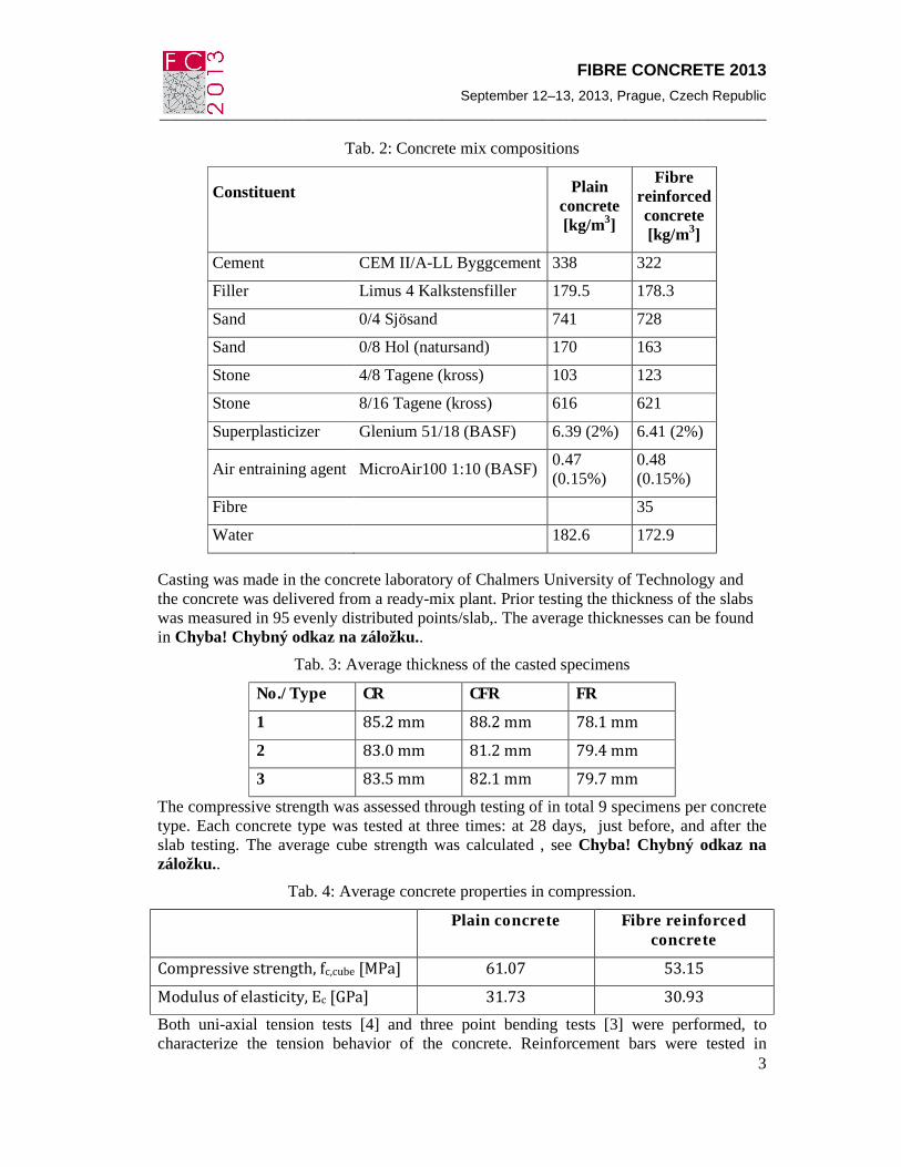
Tab. 2: Concrete mix compositions
Constituent
Plain concrete [kg/m3]
Fibre reinforced concrete [kg/m3]
Cement CEM II/A-LL Byggcement 338 322
Filler Limus 4 Kalkstensfiller 179.5 178.3
Sand 0/4 Sjösand 741 728
Sand 0/8 Hol (natursand) 170 163
Stone 4/8 Tagene (kross) 103 123
Stone 8/16 Tagene (kross) 616 621
Superplasticizer Glenium 51/18 (BASF) 6.39 (2%) 6.41 (2%)
Air entraining agent MicroAir100 1:10 (BASF) 0.47 (0.15%)
0.48 (0.15%)
Fibre
35
Water
182.6 172.9
Casting was made in the concrete laboratory of Chalmers University of Technology and the concrete was delivered from a ready-mix plant. Prior testing the thickness of the slabs was measured in 95 evenly distributed points/slab,. The average thicknesses can be found in Chyba! Chybný odkaz na záložku..
Tab. 3: Average thickness of the casted specimens
No./Type CR CFR FR
1 85.2 mm 88.2 mm 78.1 mm 2 83.0 mm 81.2 mm 79.4 mm 3 83.5 mm 82.1 mm 79.7 mm
The compressive strength was assessed through testing of in total 9 specimens per concrete type. Each concrete type was tested at three times: at 28 days, just before, and after the slab testing. The average cube strength was calculated , see Chyba! Chybný odkaz na záložku..
Tab. 4: Average concrete properties in compression.
Plain concrete Fibre reinforced concrete
Compressive strength, fc,cube [MPa] 61.07 53.15 Modulus of elasticity, Ec [GPa] 31.73 30.93 Both uni-axial tension tests [4] and three point bending tests [3] were performed, to characterize the tension behavior of the concrete. Reinforcement bars were tested in

FIBRE CONCRETE 2013 September 12–13, 2013, Prague, Czech Republic __________________________________________________________________________
4
tension, and had an average yield strength and ultimate strength of 550 and 666 MPa, respectively.
At testing, the slab was supported on 20 high-tolerance steel pipes (S355, ø=70mm, t=5 mm), see Fig. 1. Two strain gauges were glued to each pipe using a cyanoacrylate adhesive. Each support roller was calibrated prior to testing of the slabs. Each roller was tested in 3 loading cycles and the average value of the linear load-strain relation was used while calculating the reaction forces presented in this work..
Fig. 1 Support pipe
The rollers were placed on a steel plate of high tolerance (1030x125x15mm). The plate was bolted to a stiff substructure consisting of a square hollow section (VKR 150x150/6.3) bolted to a stiff support. Each support group consisted of five rollers place with 150mm between them. A loading jack was applied to a load cell (Load Indicator AB, 500kN) resting on a steel plate (280x280x30mm) in the center of the slab. Additionally, a wood fibre board (t=12 mm) was placed under the loading plate to ensure even load distribution. The test set-up, including loading plate and sub-structure can be seen in Fig. 2.
Fig. 2: Test set-up overview (left) and detail of support (right).
In addition to the 40 strain gauges glued to the support rollers, 28 linear variable differential transformers (LVDTs) were used to measure the deformation on the top surface relative to the floor, see Fig. 3. Twelve were placed over the supports, four were placed

FIBRE CONCRETE 2013 September 12–13, 2013, Prague, Czech Republic
_________________________________________________________________________
5
surrounding the loading plate in the centre of the slab and twelve were placed in an intermediate position between the loading position and the supports. The logging frequency was 1 Hz for all measurements.
Fig. 3: LVDT instrumentation
Initially, the slab was placed on four temporary supports (one on each line of support rollers). The rollers were then positioned in vertical direction by adjustable overlaying plates, see Fig. 2. These plates were positioned while controlling the strain measurements on the pipe; in this way it was secured that all supports were in contact with the slab, and thus in compression at the start of the test.
Loading was applied by means of deformation control; LVDT number LW25 was the one used to control the hydraulic jack, see Fig. 3. The initial loading speed was 0.25 mm/min. In the tests of the slabs including conventional reinforcement, the loading speed was increased to 2 mm/min after the initial crack formation and stiffness stabilisation (at a deformation around 8 mm). During the tests with steel fibres as only reinforcement, the speed was increased to 0.5 mm/min when a stable post-crack capacity was reached.
3. Results Results from all nine slab tests are summarised in Fig. 4, where the load displacement graph is presented. All the slabs with conventional reinforcement showed similar behaviour; elastic up until cracking at 25-30kN followed by a clear bending hardening behaviour. The slabs with combined reinforcement acted similarly, but with higher stiffness during the cracked hardening stage. A considerably higher capacity was obtained for one of the slabs with combined reinforcement (CFR1). This is most likely due to the unintended larger thickness of this slab, which was observed and documented, see Casting was made in the concrete laboratory of Chalmers University of Technology and the concrete was delivered from a ready-mix plant. Prior testing the thickness of the slabs

FIBRE CONCRETE 2013 September 12–13, 2013, Prague, Czech Republic __________________________________________________________________________
6
was measured in 95 evenly distributed points/slab,. The average thicknesses can be found in Chyba! Chybný odkaz na záložku.. Tab. 3. The slabs reinforced with steel fibres only, showed no bending hardening, i.e. the cracking load was the highest load applied during these tests. However, the residual capacity added by the steel fibres was significant; it corresponded aproximately to difference in the ultimate capacity observed between the two slab types including conventional reinforcement.
Fig. 4: Load vs. deflection (LVDT LW25), for all the tested slabs
The tests including conventional reinforcement were aborted at the second rupture of a reinforcement bar. While testing the slabs with only steel fibre reinforcement, the tests were aborted when the diagonal bending crack was observed also at the surface of the compressed side. The loading and unloading at a deformation of 50 to 80 mm was done because of range limitation in the load controlling deformation LVDT; the test had to be stopped in order for the LVDT to be adjusted for further loading to be possible.
In Fig. 5 sketches of the final crack patterns are shown. Although, just one slab of each reinforcement configuration is presented here, the remainder of the series showed similar behaviour. Considering the number of obtained cracks there is an obvious difference between the slabs with a hardening behavior (including conventional reinforcement), and those with the ultimate determined by the cracking load (steel fibres only). In the later, virtually no more cracks were formed once the ultimate crack pattern had formed; this occurred almost immediately following the first cracking. Furthermore, it could be observed that the number of cracks was larger in the slab with both conventional reinforcement and steel fibre reinforcement. Furthermore, the crack widths were considerably decreased by adding steel fibres. This agrees well with the previously known behaviour of steel fibre reinforced concrete; the number of cracks increases, but the crack width is generally smaller.

FIBRE CONCRETE 2013 September 12–13, 2013, Prague, Czech Republic
_________________________________________________________________________
7
Conventionally reinforced slab
Conventionally and fibre reinforced slab
Only fibre reinforced slab Fig. 5: Crack patterns from one conventionally reinforced concrete slab (CR1, top left),
one slab with steel fibres added (CFR1,top right) and steel fibre reinforcement only (FR1, bottom).
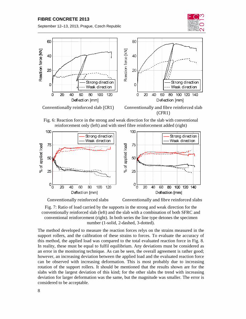
As previously described, the influence from steel fibres on the plastic redistribution was of interest. In Fig. 6 the reaction forces in supports in the strong and weak directions are presented. The reaction force was measured also for the slab reinforced only with steel fibre reinforcement; however, the lack of conventional reinforcement gives a completely symmetric structure in which no redistributions occur. For clarity, only the results from two selected slabs are presented. Similar behaviour was, however, observed throughout the test series, which can be seen in Fig. 7, where the support reactions in relation to the total load is presented for all slabs. Comparing the reaction force distribution between the strong and weak direction, a strong influence of the steel fibre reinforcement can be seen. In the slab with combined reinforcement, the load carried by the supports in the weak direction continued to increase after cracking, while almost no increase of the support reaction in weak direction was observed for the slab with conventional reinforcement only. Comparing with the overall behaviour (Fig. 4) it could be claimed that the main part of the additional load carrying capacity provided by the steel fibres are added by providing better redistribution capacity.
FIBRE CONCRETE 2013 September 12–13, 2013, Prague, Czech Republic __________________________________________________________________________
8
Conventionally reinforced slab (CR1)
Conventionally and fibre reinforced slab
(CFR1) Fig. 6: Reaction force in the strong and weak direction for the slab with conventional
reinforcement only (left) and with steel fibre reinforcement added (right)
Conventionally reinforced slabs
Conventionally and fibre reinforced slabs
Fig. 7: Ratio of load carried by the supports in the strong and weak direction for the conventionally reinforced slab (left) and the slab with a combination of both SFRC and
conventional reinforcement (right). In both series the line type detones the specimen number (1-solid, 2-dashed, 3-dotted).
The method developed to measure the reaction forces relys on the strains measured in the support rollers, and the calibration of these strains to forces. To evaluate the accuracy of this method, the applied load was compared to the total evaluated reaction force in Fig. 8. In reality, these must be equal to fulfil equilibrium. Any deviations must be considered as an error in the monitoring technique. As can be seen, the overall agreement is rather good; however, an increasing deviation between the applied load and the evaluated reaction force can be observed with increasing deformation. This is most probably due to increasing rotation of the support rollers. It should be mentioned that the results shown are for the slabs with the largest deviation of this kind; for the other slabs the trend with increasing deviation for larger deformation was the same, but the magnitude was smaller. The error is considered to be acceptable.

FIBRE CONCRETE 2013 September 12–13, 2013, Prague, Czech Republic
_________________________________________________________________________
9
Conventionally reinforced slab
Conventionally and fibre reinforced slab
Only fibre reinforced slab
Fig. 8: Applied load and measured reaction force for one conventionally reinforced concrete slab (CR1, top left), one slab with steel fibres added (CFR1,top right) and steel
fibre reinforcement only (FR1, bottom)
4. Conclusions It could be concluded that the steel fibres, just as expected, provided a significant addition in terms of ductility. Furthermore, also the crack pattern was affected as expected: with steel fibre reinforced concrete combined with conventional reinforcement more cracks developed with smaller crack widths. Perhaps the most noteworthy conclusion is the effect from the inclusion of steel fibres on the load distribution. This study showed that addition of steel fibre reinforcement can increase the redistribution capacity. This was found by monitoring the reaction forces in a statically indeterminate slab.
The slabs reinforced with fibres only did not experience any bending hardening. It is interesting to note that the post-crack capacity in these slabs, entirely depending on the fibres in the concrete, roughly corresponds to the addition in ultimate load capacity which the fibres provided when combined with conventional reinforcement. It could be argued that this is a coincidence, valid only for this specific geometry and material. However, with

FIBRE CONCRETE 2013 September 12–13, 2013, Prague, Czech Republic __________________________________________________________________________
10
further research, a simplified model to estimate the beneficial effect of steel fibres, valid for a limited range of standard elements, could be established.
The developed method to monitor the reaction forces by the use of strain gauges on steel pipes was successful. Additional parameters to be varied in further studies would be the ratio of conventional reinforcement in each direction (i.e. make the weak direction even weaker) and the steel fibre contents.
Acknowledgements This research were funded by the European Community´s Seventh Framework Programme under grant agreement NMP2-LA-2009-228663 (TailorCrete). More information on the project TailorCrete can be found at www.tailorcrete.com.
References [1] Barros, J.A.O. and Figueiras, J.A., Flexural behavior of SFRC: Testing and
modeling. Journal of Materials in Civil Engineering, 1999. 11(4): p. 331-339.
[2] Vandewalle, L., Cracking behaviour of concrete beams reinforced with a combination of ordinary reinforcement and steel fibers. Materials and Structures/Materiaux et Constructions, 2000. 33(227): p. 164-170.
[3] RILEM TC 162-TDF, Bending test. Materials and Structures, 2002. 35(9): p. 579-582.
[4] RILEM TC 162-TDF, Uni-axial tension test for steel fibre reinforced concrete. Materials and Structures, 2001. 34(1): p. 3-6.
[5] Sorelli, L.G., Meda, A. and Plizzari, G.A., Steel Fiber Concrete Slabs on Ground: A Structural Matter. ACI Structural Journal, 2006. 103(4): p. 551-558.
[6] Michels, J., Waldmann, D., Maas, S. and Zürbes, A., Steel fibers as only reinforcement for flat slab construction - Experimental investigation and design. Construction and Building Materials, 2012. 26(1): p. 145-155.
[7] Nguyen-Minh, L., Rovňák, M., Tran-Ngoc, T. and Le-Phuoc, T., Punching shear resistance of post-tensioned steel fiber reinforced concrete flat plates. Engineering Structures, 2012. 45: p. 324-337.
[8] Maya, L.F., Fernández Ruiz, M., Muttoni, A. and Foster, S.J., Punching shear strength of steel fibre reinforced concrete slabs. Engineering Structures, 2012. 40: p. 83-94.
[9] Johansen, K.W., Yield-line formulae for slabs1972, London: Cement and Concrete Association. 0-7210-0819-4.
[10] Hillerborg, A., Strip method design handbook1996, London: E & FN Spon.
[11] Di Prisco, M., Plizzari, G. and Vandewalle, L., Fibre reinforced concrete: new design perspectives. Materials and Structures, 2009. 42(9): p. 1261-1281.