experionpks c300 controller capacity · experionpks c300 controller capacity, ep03-300-511 2 ....
TRANSCRIPT
Honeywell Internal
ExperionPKS C300 Controller Capacity
Technical Information
EP03-300-511 [Keywords] July 2019, Version 1
ExperionPKS C300 Controller Capacity, EP03-300-511 2
Version 1 Honeywell Proprietary July 2019 Honeywell Internal
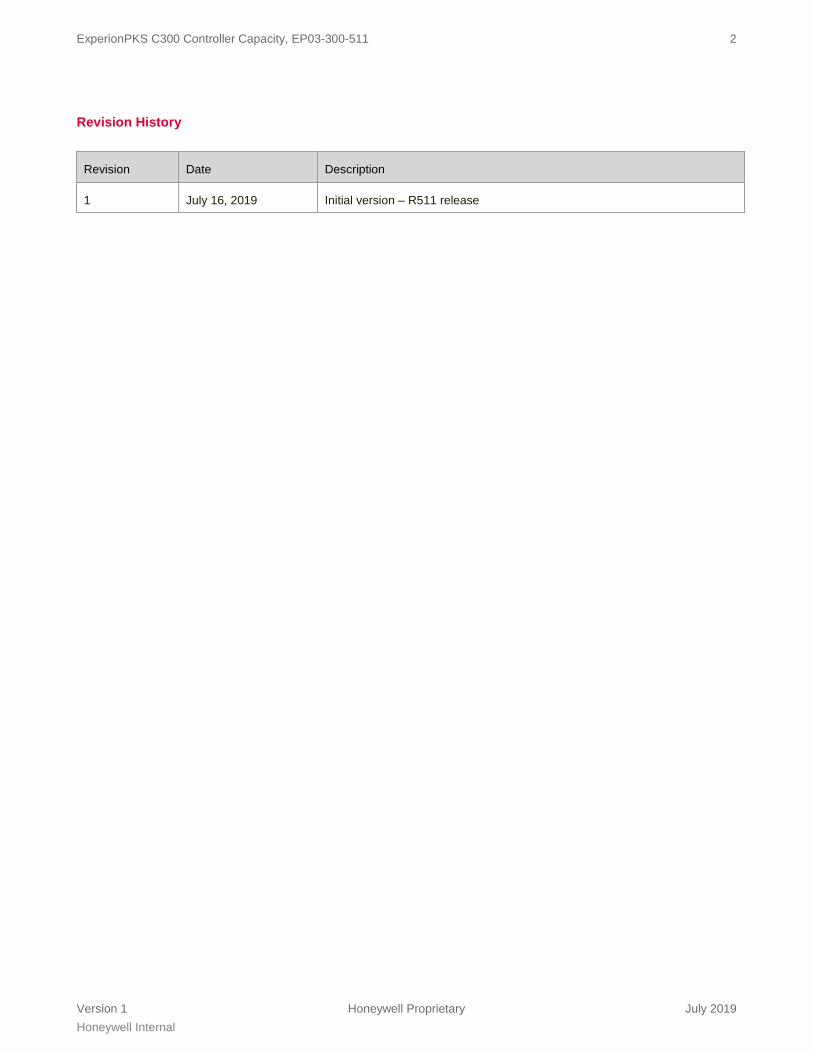
Revision History
Revision Date Description
1 July 16, 2019 Initial version – R511 release

ExperionPKS C300 Controller Capacity, EP03-300-511 3
Version 1 Honeywell Proprietary July 2019 Honeywell Internal
Table of Contents
1.0 Product Introduction .................................................................................................................................................. 4
1.1 Experion System ....................................................................................................................................................... 4 1.2 Architecture Overview ............................................................................................................................................... 4 1.3 Experion Controller Overview ................................................................................................................................... 5
2.0 Control Capacity and Performance ........................................................................................................................... 6 2.1 Controller Definitions ................................................................................................................................................. 6 2.2 Control Network Capacity ......................................................................................................................................... 7 2.3 C300 Capacity and Performance .............................................................................................................................. 8
2.3.1 C300 Configuration Options ............................................................................................................................................. 8 2.3.2 C300 Redundancy.............................................................................................................................................................10 2.3.3 C300 Communication Performance .................................................................................................................................10 2.3.4 C300 Processing and Memory Capacity Model ..............................................................................................................14 2.3.5 C300 Memory ....................................................................................................................................................................17 2.3.6 C300 CEE Block Processing & Memory Usage Models .................................................................................................17 2.3.7 IOLIM Communication Specifications .............................................................................................................................20 2.3.8 C300-20 and C300-50 Functional Comparison ................................................................................................................21
3.0 Engineering Tools Performance Specifications ..................................................................................................... 22 3.1 Terms ...................................................................................................................................................................... 22 3.2 Tools Performance Specifications ........................................................................................................................... 23
4.0 C300 I/O Capacities ................................................................................................................................................... 25 4.1 IO UNIT Definition Table ......................................................................................................................................... 25

ExperionPKS C300 Controller Capacity, EP03-300-511 4
Version 1 Honeywell Proprietary July 2019 Honeywell Internal
1.0 Product Introduction
1.1 Experion System
The Experion® Process Knowledge System (PKS) is Honeywell’s unified control system for process, business, and asset management that helps industrial manufacturers increase their profitability and productivity. Experion takes customers well beyond distributed control system (DCS) functionality with an advanced automation platform solution and innovative application integration to improve business performance and peace of mind. Refer to the “Experion CEE-based Controllers and I/O Overview” (document number EP03-290-xxx) for prerequisite information. This document is written with the expectation that the reader understands the information and concepts covered in the overview document.
1.2 Architecture Overview
The ExperionPKS platform comprises many different integrated hardware and software solutions depending upon the needs of the application. This pictured architecture is a representation of many of the possible nodes that can be utilized in the ExperionPKS architecture. Note that the architecture is highly scalable and not all nodes are necessary or required.
Figure 1 - Sample Experion Architecture
ExperionPKS C300 Controller Capacity, EP03-300-511 5
Version 1 Honeywell Proprietary July 2019 Honeywell Internal
1.3 Experion Controller Overview
Honeywell offers multiple ExperionPKS controllers, ranging from embedded controller platforms with dedicated IO hardware to PC based control environments for supervisory control tasks or simulation. They all support one or more different network types to integrate the controllers with the ExperionPKS Server. They share a common Control Execution Environment (CEE) software infrastructure and a common builder tool. Together with the different station types, they form the ExperionPKS system. This specifications document provides details specifically related to the ExperionPKS C300 controller.
ExperionPKS C300 Controller Capacity, EP03-300-511 6
Version 1 Honeywell Proprietary July 2019 Honeywell Internal
2.0 Control Capacity and Performance
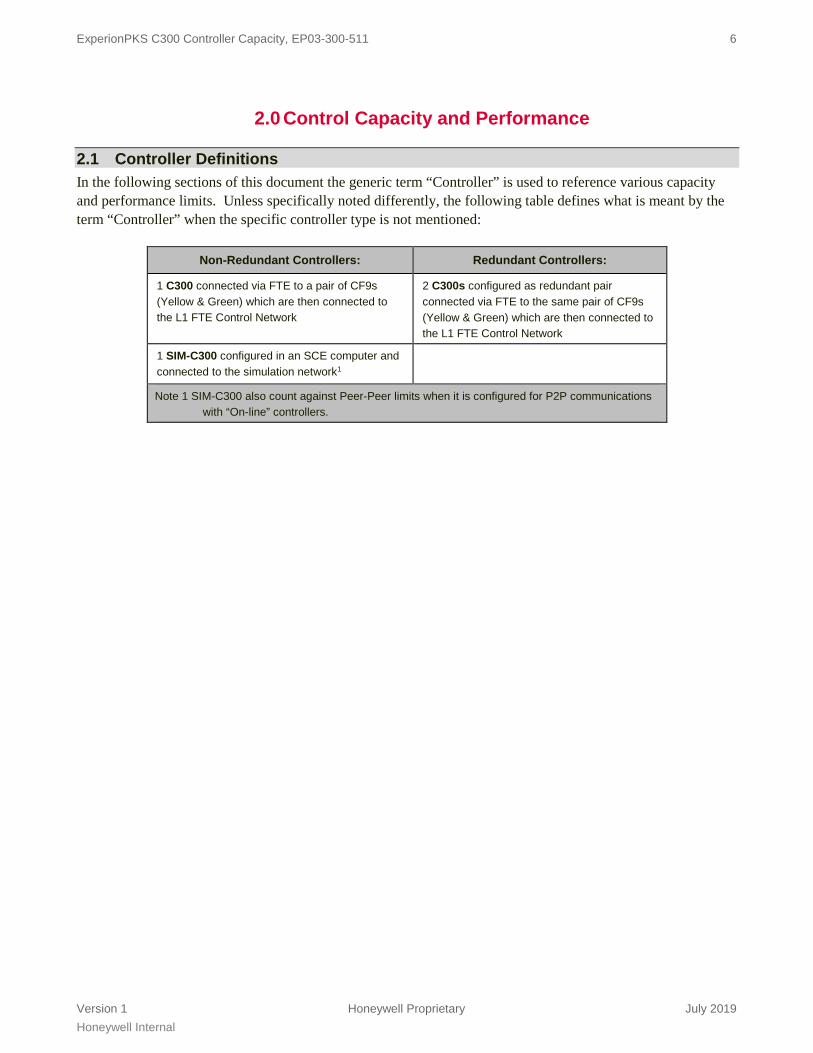
2.1 Controller Definitions In the following sections of this document the generic term “Controller” is used to reference various capacity and performance limits. Unless specifically noted differently, the following table defines what is meant by the term “Controller” when the specific controller type is not mentioned:
Non-Redundant Controllers: Redundant Controllers:
1 C300 connected via FTE to a pair of CF9s (Yellow & Green) which are then connected to the L1 FTE Control Network
2 C300s configured as redundant pair connected via FTE to the same pair of CF9s (Yellow & Green) which are then connected to the L1 FTE Control Network
1 SIM-C300 configured in an SCE computer and connected to the simulation network1
Note 1 SIM-C300 also count against Peer-Peer limits when it is configured for P2P communications with “On-line” controllers.
ExperionPKS C300 Controller Capacity, EP03-300-511 7
Version 1 Honeywell Proprietary July 2019 Honeywell Internal
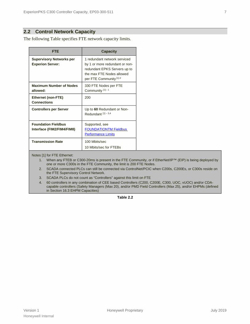
2.2 Control Network Capacity The following Table specifies FTE network capacity limits.
FTE Capacity
Supervisory Networks per Experion Server:
1 redundant network serviced by 1 or more redundant or non-redundant EPKS Servers up to the max FTE Nodes allowed per FTE Community [1]-2
Maximum Number of Nodes allowed:
330 FTE Nodes per FTE Community [1] - 1
Ethernet (non-FTE) Connections
200
Controllers per Server Up to 60 Redundant or Non-Redundant [1] – 3,4
Foundation Fieldbus Interface (FIM2/FIM4/FIM8)
Supported, see FOUNDATIONTM Fieldbus Performance Limits
Transmission Rate 100 Mbits/sec 10 Mbits/sec for FTEBs
Notes [1] for FTE Ethernet: 1. When any FTEB or C300-20ms is present in the FTE Community, or if EtherNet/IP™ (EIP) is being deployed by
one or more C300s in the FTE Community, the limit is 200 FTE Nodes. 2. SCADA connected PLCs can still be connected via ControlNet/PCIC when C200s, C200Es, or C300s reside on
the FTE Supervisory Control Network. 3. SCADA PLCs do not count as “Controllers” against this limit on FTE 4. 60 controllers in any combination of CEE based Controllers (C200, C200E, C300, UOC, vUOC) and/or CDA-
capable controllers (Safety Managers (Max 20), and/or PMD Field Controllers (Max 25), and/or EHPMs (defined in Section 16.3 EHPM Capacities)
Table 2.2
Honeywell Internal
2.3 C300 Capacity and Performance
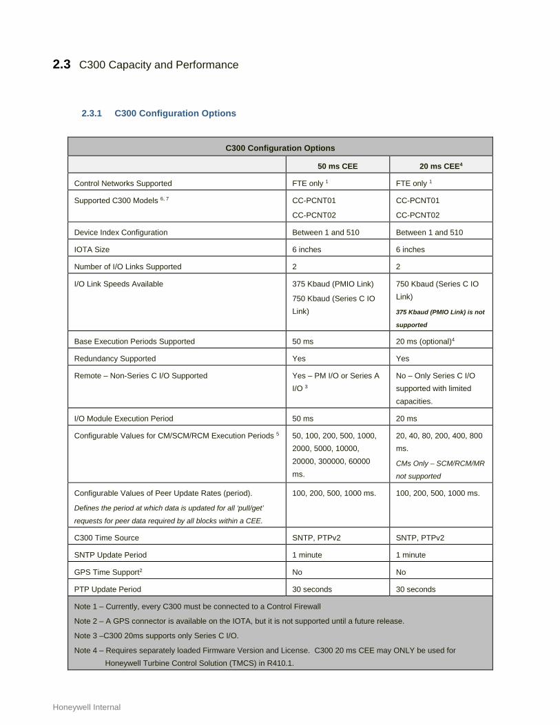
2.3.1 C300 Configuration Options
C300 Configuration Options
50 ms CEE 20 ms CEE4
Control Networks Supported FTE only 1 FTE only 1
Supported C300 Models 6, 7 CC-PCNT01
CC-PCNT02
CC-PCNT01
CC-PCNT02
Device Index Configuration Between 1 and 510 Between 1 and 510
IOTA Size 6 inches 6 inches
Number of I/O Links Supported 2 2
I/O Link Speeds Available 375 Kbaud (PMIO Link)
750 Kbaud (Series C IO Link)
750 Kbaud (Series C IO Link)
375 Kbaud (PMIO Link) is not
supported
Base Execution Periods Supported 50 ms 20 ms (optional)4
Redundancy Supported Yes Yes
Remote – Non-Series C I/O Supported Yes – PM I/O or Series A I/O 3
No – Only Series C I/O supported with limited capacities.
I/O Module Execution Period 50 ms 20 ms
Configurable Values for CM/SCM/RCM Execution Periods 5 50, 100, 200, 500, 1000, 2000, 5000, 10000, 20000, 300000, 60000 ms.
20, 40, 80, 200, 400, 800 ms.
CMs Only – SCM/RCM/MR
not supported
Configurable Values of Peer Update Rates (period).
Defines the period at which data is updated for all ‘pull/get’
requests for peer data required by all blocks within a CEE.
100, 200, 500, 1000 ms. 100, 200, 500, 1000 ms.
C300 Time Source SNTP, PTPv2 SNTP, PTPv2
SNTP Update Period 1 minute 1 minute
GPS Time Support2 No No
PTP Update Period 30 seconds 30 seconds
Note 1 – Currently, every C300 must be connected to a Control Firewall
Note 2 – A GPS connector is available on the IOTA, but it is not supported until a future release.
Note 3 –C300 20ms supports only Series C I/O.
Note 4 – Requires separately loaded Firmware Version and License. C300 20 ms CEE may ONLY be used for Honeywell Turbine Control Solution (TMCS) in R410.1.

ExperionPKS C300 Controller Capacity, EP03-300-511 9
Version 1 Honeywell Proprietary July 2019 Honeywell Internal
Note 5- Slower execution periods are supported for Profit Controller Block only
Note 6- C300 controller CC-PCNT02 replaces CC-PCNT01 for new installations and field replacements.
Note 7- C300 controller must use CC-PCNT02 model with extended functionality firmware image for C300 extended functionalities (EIM, Profit Controller)
ExperionPKS C300 Controller Capacity, EP03-300-511 10
Version 1 Honeywell Proprietary July 2019 Honeywell Internal
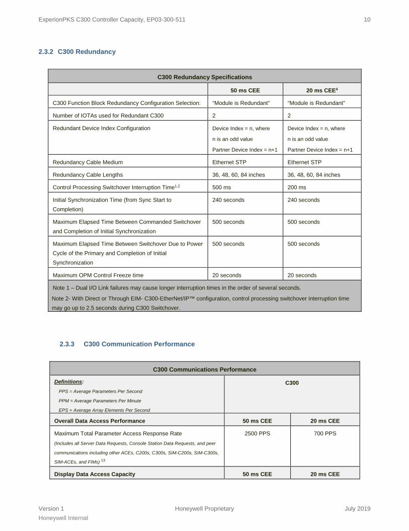
2.3.2 C300 Redundancy
C300 Redundancy Specifications
50 ms CEE 20 ms CEE4
C300 Function Block Redundancy Configuration Selection: “Module is Redundant” “Module is Redundant”
Number of IOTAs used for Redundant C300 2 2
Redundant Device Index Configuration Device Index = n, where
n is an odd value
Partner Device Index = n+1
Device Index = n, where
n is an odd value
Partner Device Index = n+1
Redundancy Cable Medium Ethernet STP Ethernet STP
Redundancy Cable Lengths 36, 48, 60, 84 inches 36, 48, 60, 84 inches
Control Processing Switchover Interruption Time1,2 500 ms 200 ms
Initial Synchronization Time (from Sync Start to Completion)
240 seconds 240 seconds
Maximum Elapsed Time Between Commanded Switchover and Completion of Initial Synchronization
500 seconds 500 seconds
Maximum Elapsed Time Between Switchover Due to Power Cycle of the Primary and Completion of Initial Synchronization
500 seconds 500 seconds
Maximum OPM Control Freeze time 20 seconds 20 seconds
Note 1 – Dual I/O Link failures may cause longer interruption times in the order of several seconds.
Note 2- With Direct or Through EIM- C300-EtherNet/IP™ configuration, control processing switchover interruption time may go up to 2.5 seconds during C300 Switchover.
2.3.3 C300 Communication Performance
C300 Communications Performance
Definitions:
PPS = Average Parameters Per Second
PPM = Average Parameters Per Minute
EPS = Average Array Elements Per Second
C300
Overall Data Access Performance 50 ms CEE 20 ms CEE
Maximum Total Parameter Access Response Rate (Includes all Server Data Requests, Console Station Data Requests, and peer
communications including other ACEs, C200s, C300s, SIM-C200s, SIM-C300s,
SIM-ACEs, and FIMs) 13
2500 PPS 700 PPS
Display Data Access Capacity 50 ms CEE 20 ms CEE

ExperionPKS C300 Controller Capacity, EP03-300-511 11
Version 1 Honeywell Proprietary July 2019 Honeywell Internal
C300 Communications Performance
Maximum Total Subscribed Parameters per C300 (Includes all Server Data Requests + Console Station Data Requests)) 13
4000 4000
Request/Response Data Access Performance 50 ms CEE 20 ms CEE
Max Request/Response Parameter Access Rate (Includes all Slow Server Data Requests, e.g. Greater than 10 sec OPC data,
Slow History, Data Writes, etc.)
3000 PPM Read
1500 PPM Write
750 PPM Read
375 PPM Write
Peer-to-Peer Performance 50 ms CEE 20 ms CEE
Maximum Initiator Pull/Get Subscribe Rate to all target nodes. (incoming data) 7
1000 PPS 250 PPS
Maximum Target Publish Rate to Pull/Get Subscriptions from all initiator nodes. (outgoing data) 8
1000 PPS 250 PPS
Peer-to-Peer Subscription Capacity / Update Rate 50 ms CEE 20 ms CEE
Total Maximum C300 peer capacity per update rate choices
100 @ 100 ms 200 @ 200 ms 500 @ 500 ms 1000 @ 1 sec
25@ 100 ms 50 @ 200 ms
125 @ 500 ms 250 @ 1 sec
Maximum C300 peer capacity for non-CEE parameter references
(Includes peer references to SM, PMD FC, EHPM, and Server Point parameters and is included in the total limit for the row above)
500 parameters NA
Push/Store Request Capacity 50 ms CEE 20 ms CEE
Maximum number of Push/Store Requests to all target nodes and local IOLink EEs, in progress simultaneously
800 800
Maximum number of Push/Store Requests initiated in a single CEE execution cycle
200 200
Push/Store Request Performance 50 ms CEE 20 ms CEE
Maximum Push/Store Request Rate to all target nodes and local IOLink EEs2
50 PPS 12 PPS
Maximum Response Rate to Push/Store Requests from all initiator nodes2
50 PPS 12 PPS
Whole Array Capacity 50 ms CEE 20 ms CEE
Max Array Size for Whole Array Transfer 8K bytes (1000 float64s)
8K bytes (1000 float64s)
Initiator’s Max Whole Array Connection References 25 25
Responder’s Max Whole Array Connections (from all peers using pub-sub)
15 15
Initiator’s Max Whole Array Connection References (to all peers using request/response)
5 5

ExperionPKS C300 Controller Capacity, EP03-300-511 12
Version 1 Honeywell Proprietary July 2019 Honeywell Internal
C300 Communications Performance
Responder’s Max Whole Array Connections (to all peers using request/response)
5 5
Peer-Peer Whole Array Transfer Performance 50 ms CEE 20 ms CEE
Max Initiator Whole Array Request Rate (to all peers) 2500 EPS 600 EPS
Max Target Node Response Rate to Whole Array Pull/Get Requests
(from all initiator nodes)
1500 EPS 350 EPS
Initiator Whole Array Push/Store Rate 1000 EPS 250 EPS
Target Node Whole Array Response Rate to Push/Store Requests
(from all initiator nodes)
1000 EPS 250 EPS
Peer-to-Peer Capacity 50 ms CEE 20 ms CEE
Peer Connection Units (PCUs) 2, 9
(Number of remote CEEs that this C300 can initiate a peer connection with)
303
(Includes total of all other
UOC/vUOC, ACEs, SIM-
ACEs, C200s, C200Es,
C300s, LIOMs, SIM-
CXXXs, IOLIMs, Server
Peers, SMs, WDMs, and/or
Primary FIMs)
53
(Includes total of other
UOC/vUOC,ACEs, SIM-
ACEs, C200s, C200Es,
C300s, SIM-C200s, SIM-
C200Es, SIM-C300s)
Peer-to-Peer Capacity using Exchange FB 50 ms CEE 20 ms CEE
Maximum Number of REQUEST blocks per C300 32 Not Supported
Maximum Number of RESPONSE blocks per C300 32 Not Supported
Maximum Number of Target Devices for REQUEST blocks per C300 4
8 Not Supported
Maximum Number of Remote Initiating Devices for RESPONSE block data per C300
8 Not Supported
Maximum Request Rate using Exchange blocks to all target nodes11
500 PPS Not Supported
Maximum Response Rate to Exchange Requests from all initiator nodes 11
500 PPS Not Supported
PCDI Capacity and Performance 50 ms CEE 20 ms CEE
Maximum Number of Modbus TCP devices 5,10 (represented by PCDI Master blocks)
8 3
Maximum Number of Serial Modbus Devices per Gateway 16 3
Maximum Number of Serial Modbus Devices per C300 (8 * 16 of above two specifications)
128 3
Maximum Number of PCDI Request blocks assigned to a PCDI Master block
64 8
ExperionPKS C300 Controller Capacity, EP03-300-511 13
Version 1 Honeywell Proprietary July 2019 Honeywell Internal
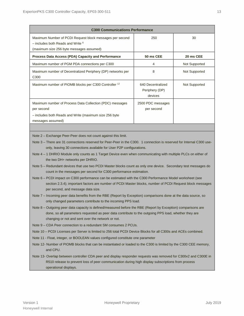
C300 Communications Performance
Maximum Number of PCDI Request block messages per second – includes both Reads and Write 6 (maximum size 256 byte messages assumed)
250 30
Process Data Access (PDA) Capacity and Performance 50 ms CEE 20 ms CEE
Maximum number of PGM PDA connections per C300 4 Not Supported
Maximum number of Decentralized Periphery (DP) networks per C300
8 Not Supported
Maximum number of PIOMB blocks per C300 Controller 12 640 Decentralized Periphery (DP)
devices
Not Supported
Maximum number of Process Data Collection (PDC) messages per second
– includes both Reads and Write (maximum size 256 byte messages assumed)
2500 PDC messages per second
Note 2 – Exchange Peer-Peer does not count against this limit.
Note 3 – There are 31 connections reserved for Peer-Peer in the C300. 1 connection is reserved for Internal C300 use-only, leaving 30 connections available for User P2P configurations.
Note 4 – 1 DHRIO Module only counts as 1 Target Device even when communicating with multiple PLCs on either of the two DH+ networks per DHRIO.
Note 5 – Redundant devices that use two PCDI Master blocks count as only one device. Secondary test messages do count in the messages per second for C300 performance estimation.
Note 6 – PCDI impact on C300 performance can be estimated with the C300 Performance Model worksheet (see section 2.3.4); important factors are number of PCDI Master blocks, number of PCDI Request block messages per second, and message data size.
Note 7 – Incoming peer data benefits from the RBE (Report by Exception) comparisons done at the data source, so only changed parameters contribute to the incoming PPS load.
Note 8 – Outgoing peer data capacity is defined/measured before the RBE (Report by Exception) comparisons are done, so all parameters requested as peer data contribute to the outgoing PPS load, whether they are changing or not and sent over the network or not.
Note 9 – CDA Peer connection to a redundant SM consumes 2 PCUs.
Note 10 – PCDI Licenses per Server is limited to 256 total PCDI Device Blocks for all C300s and ACEs combined.
Note 11 - Float, integer, or BOOLEAN values configured constitute one parameter
Note 12- Number of PIOMB blocks that can be instantiated or loaded to the C300 is limited by the C300 CEE memory, and CPU.
Note 13- Overlap between controller CDA peer and display responder requests was removed for C300v2 and C300E in R510 release to prevent loss of peer communication during high display subscriptions from process operational displays.
ExperionPKS C300 Controller Capacity, EP03-300-511 14
Version 1 Honeywell Proprietary July 2019 Honeywell Internal
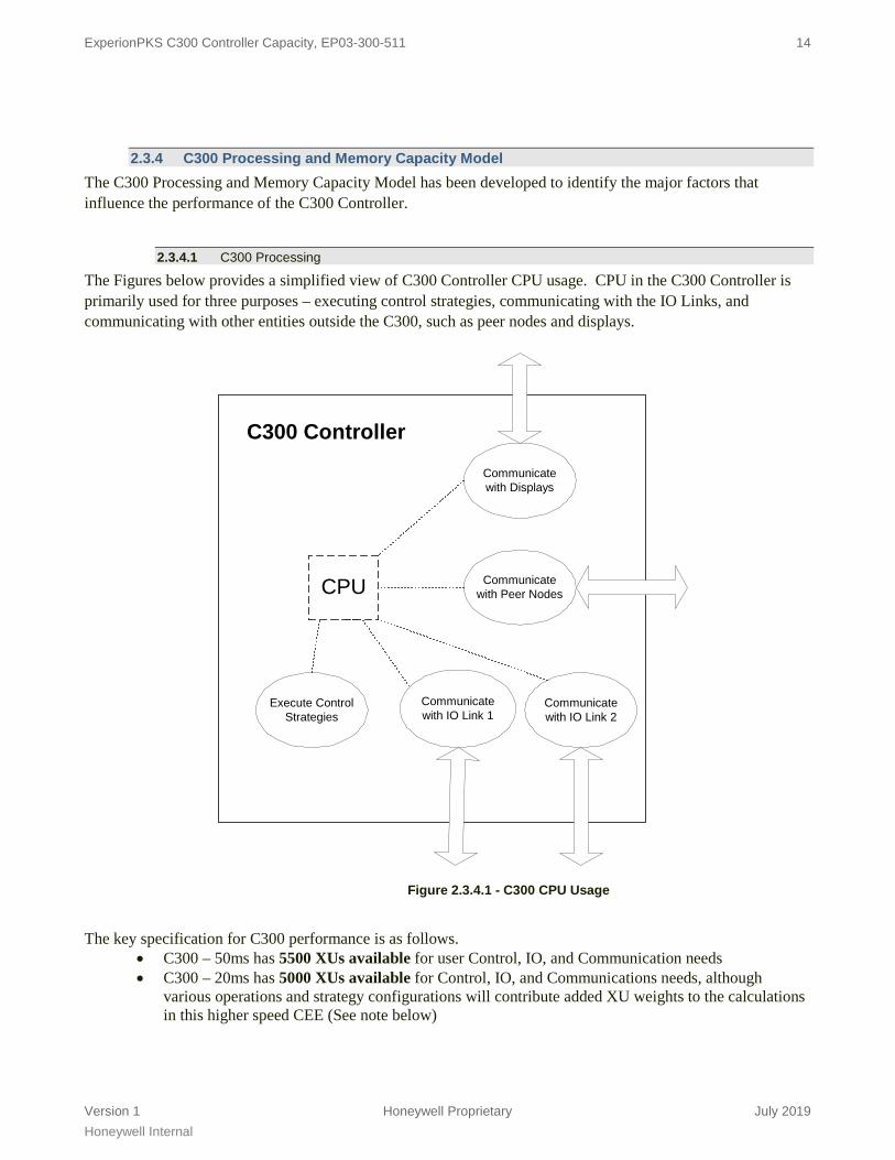
2.3.4 C300 Processing and Memory Capacity Model The C300 Processing and Memory Capacity Model has been developed to identify the major factors that influence the performance of the C300 Controller.
2.3.4.1 C300 Processing
The Figures below provides a simplified view of C300 Controller CPU usage. CPU in the C300 Controller is primarily used for three purposes – executing control strategies, communicating with the IO Links, and communicating with other entities outside the C300, such as peer nodes and displays.
C300 Controller
CPU
Execute ControlStrategies
Communicatewith Peer Nodes
Communicatewith IO Link 1
Communicatewith IO Link 2
Communicatewith Displays
Figure 2.3.4.1 - C300 CPU Usage
The key specification for C300 performance is as follows.
• C300 – 50ms has 5500 XUs available for user Control, IO, and Communication needs • C300 – 20ms has 5000 XUs available for Control, IO, and Communications needs, although
various operations and strategy configurations will contribute added XU weights to the calculations in this higher speed CEE (See note below)

ExperionPKS C300 Controller Capacity, EP03-300-511 15
Version 1 Honeywell Proprietary July 2019 Honeywell Internal
Figure 2.3.4.1 - C300 XUs Available to User
2.3.4.2 C300 Control
Control requirements of a C300 are estimated in PUs, using a PU estimation spreadsheet similar to those used for C200 and ACE. The definition of a PU (see Section 1.4) does not change with the introduction of C300, because the PU definition is platform independent. C300 PU specifications are provided for the same set of typical module types (e.g. Small Analog Data Acquisition CM, Regulatory Control CM, Device Control CM, etc.) as already documented for C200 and ACE. PU specifications are not provided for Series C IO Modules and PM IO Modules, because the IO Module execution for these IO types is not part of CEE. Processing load attributed to the execution of Series C IO Modules and PM IO Modules is accounted for in the IO component of C300 CPU usage.
2.3.4.3 C300 IO
Performance testing has determined that the following factors have the greatest influence on the amount of CPU used to support and communicate with IO.
• IO Link 1 Type – PM IO, Series C IO, or None • IO Link 2 Type – PM IO, Series C IO, or None • IO Link 1 LUs – estimated from LU estimation sheet • IO Link 2 LUs – estimated from LU estimation sheet • Number of FTEB supported IO modules
CPU Usage
0%
100%
Free
Comm
Control
IO
Base
XUs for user
ExperionPKS C300 Controller Capacity, EP03-300-511 16
Version 1 Honeywell Proprietary July 2019 Honeywell Internal
The C300 performance model estimates the XUs required to support IO, when provided with estimates for the above factors. The LU estimation worksheet contains all the details needed to estimate the LUs associated with a given IO Link and its complement of PM IOPs or Series C IOMs. To summarize, the number of LUs is dependent on the following items.
• Link Type - PM IO or Series C IO • Number of IO Modules, and for each its type (AI, AO, DI, DO, etc.), scan rate, and redundancy
configuration • Number of AO connections – quantity and rate • Number of DO connections – quantity and rate • Number of SCM reads and writes per second of IO Link data
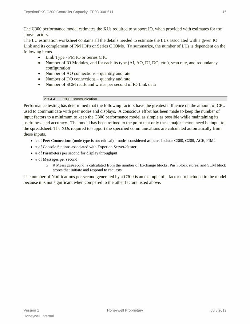
2.3.4.4 C300 Communication
Performance testing has determined that the following factors have the greatest influence on the amount of CPU used to communicate with peer nodes and displays. A conscious effort has been made to keep the number of input factors to a minimum to keep the C300 performance model as simple as possible while maintaining its usefulness and accuracy. The model has been refined to the point that only these major factors need be input to the spreadsheet. The XUs required to support the specified communications are calculated automatically from these inputs.
• # of Peer Connections (node type is not critical) – nodes considered as peers include C300, C200, ACE, FIM4 • # of Console Stations associated with Experion Server/cluster • # of Parameters per second for display throughput • # of Messages per second
o # Messages/second is calculated from the number of Exchange blocks, Push block stores, and SCM block stores that initiate and respond to requests
The number of Notifications per second generated by a C300 is an example of a factor not included in the model because it is not significant when compared to the other factors listed above.
ExperionPKS C300 Controller Capacity, EP03-300-511 17
Version 1 Honeywell Proprietary July 2019 Honeywell Internal
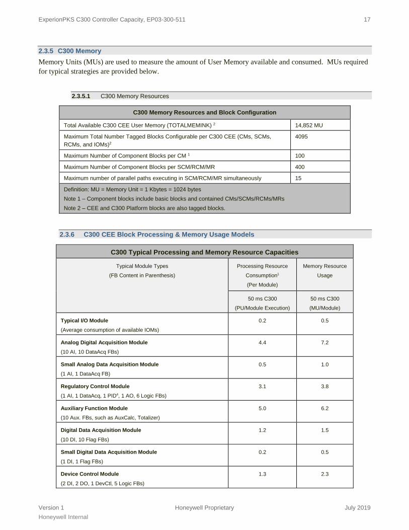
2.3.5 C300 Memory Memory Units (MUs) are used to measure the amount of User Memory available and consumed. MUs required for typical strategies are provided below.
2.3.5.1 C300 Memory Resources
C300 Memory Resources and Block Configuration
Total Available C300 CEE User Memory (TOTALMEMINK) 2 14,852 MU
Maximum Total Number Tagged Blocks Configurable per C300 CEE (CMs, SCMs, RCMs, and IOMs)2
4095
Maximum Number of Component Blocks per CM 1 100
Maximum Number of Component Blocks per SCM/RCM/MR 400
Maximum number of parallel paths executing in SCM/RCM/MR simultaneously 15
Definition: MU = Memory Unit = 1 Kbytes = 1024 bytes Note 1 – Component blocks include basic blocks and contained CMs/SCMs/RCMs/MRs Note 2 – CEE and C300 Platform blocks are also tagged blocks.
2.3.6 C300 CEE Block Processing & Memory Usage Models
C300 Typical Processing and Memory Resource Capacities
Typical Module Types
(FB Content in Parenthesis)
Processing Resource
Consumption1
(Per Module)
Memory Resource
Usage
50 ms C300
(PU/Module Execution)
50 ms C300
(MU/Module)
Typical I/O Module
(Average consumption of available IOMs)
0.2 0.5
Analog Digital Acquisition Module
(10 AI, 10 DataAcq FBs)
4.4 7.2
Small Analog Data Acquisition Module
(1 AI, 1 DataAcq FB)
0.5 1.0
Regulatory Control Module
(1 AI, 1 DataAcq, 1 PID4, 1 AO, 6 Logic FBs)
3.1 3.8
Auxiliary Function Module
(10 Aux. FBs, such as AuxCalc, Totalizer)
5.0 6.2
Digital Data Acquisition Module
(10 DI, 10 Flag FBs)
1.2 1.5
Small Digital Data Acquisition Module
(1 DI, 1 Flag FBs)
0.2 0.5
Device Control Module
(2 DI, 2 DO, 1 DevCtl, 5 Logic FBs)
1.3 2.3
ExperionPKS C300 Controller Capacity, EP03-300-511 18
Version 1 Honeywell Proprietary July 2019 Honeywell Internal
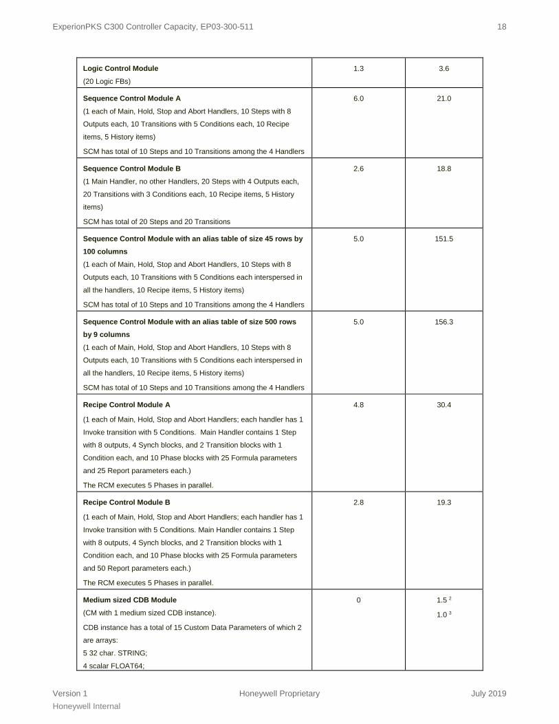
Logic Control Module
(20 Logic FBs)
1.3 3.6
Sequence Control Module A
(1 each of Main, Hold, Stop and Abort Handlers, 10 Steps with 8
Outputs each, 10 Transitions with 5 Conditions each, 10 Recipe
items, 5 History items)
SCM has total of 10 Steps and 10 Transitions among the 4 Handlers
6.0 21.0
Sequence Control Module B
(1 Main Handler, no other Handlers, 20 Steps with 4 Outputs each,
20 Transitions with 3 Conditions each, 10 Recipe items, 5 History
items)
SCM has total of 20 Steps and 20 Transitions
2.6 18.8
Sequence Control Module with an alias table of size 45 rows by 100 columns
(1 each of Main, Hold, Stop and Abort Handlers, 10 Steps with 8
Outputs each, 10 Transitions with 5 Conditions each interspersed in
all the handlers, 10 Recipe items, 5 History items)
SCM has total of 10 Steps and 10 Transitions among the 4 Handlers
5.0 151.5
Sequence Control Module with an alias table of size 500 rows by 9 columns (1 each of Main, Hold, Stop and Abort Handlers, 10 Steps with 8
Outputs each, 10 Transitions with 5 Conditions each interspersed in
all the handlers, 10 Recipe items, 5 History items)
SCM has total of 10 Steps and 10 Transitions among the 4 Handlers
5.0 156.3
Recipe Control Module A
(1 each of Main, Hold, Stop and Abort Handlers; each handler has 1
Invoke transition with 5 Conditions. Main Handler contains 1 Step
with 8 outputs, 4 Synch blocks, and 2 Transition blocks with 1
Condition each, and 10 Phase blocks with 25 Formula parameters
and 25 Report parameters each.)
The RCM executes 5 Phases in parallel.
4.8 30.4
Recipe Control Module B
(1 each of Main, Hold, Stop and Abort Handlers; each handler has 1
Invoke transition with 5 Conditions. Main Handler contains 1 Step
with 8 outputs, 4 Synch blocks, and 2 Transition blocks with 1
Condition each, and 10 Phase blocks with 25 Formula parameters
and 50 Report parameters each.)
The RCM executes 5 Phases in parallel.
2.8 19.3
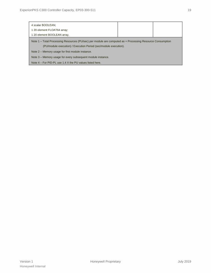
Medium sized CDB Module
(CM with 1 medium sized CDB instance).
CDB instance has a total of 15 Custom Data Parameters of which 2
are arrays:
5 32 char. STRING;
4 scalar FLOAT64;
0 1.5 2
1.0 3
ExperionPKS C300 Controller Capacity, EP03-300-511 19
Version 1 Honeywell Proprietary July 2019 Honeywell Internal
4 scalar BOOLEAN;
1 20 element FLOAT64 array;
1 20 element BOOLEAN array.
Note 1 – Total Processing Resources (PU/sec) per module are computed as = Processing Resource Consumption
(PU/module execution) / Execution Period (sec/module execution).
Note 2 – Memory usage for first module instance.
Note 3 – Memory usage for every subsequent module instance.
Note 4 – For PID-PL use 1.4 X the PU values listed here.

ExperionPKS C300 Controller Capacity, EP03-300-511 20
Version 1 Honeywell Proprietary July 2019 Honeywell Internal
2.3.7 IOLIM Communication Specifications
IOLIM Communications Performance
Maximum Total Parameter Access Response Rate 1
6000 PPS
Maximum IOLIM to CEE Parameter Access Response Rate (PEERRATEAVG and PEERRATEMAX)
5120 PPS (Max 1280 channels @ 250 ms publish rate)
Maximum number of Display Parameters per IOLIM (DISPRATEAVG and DISPRATEMAX)
1000 PPS
Maximum Initiator Node Pull/Get Request Rate2 (PEERINITAVG and PEERINI AX)
1000 PPS (Restricted by Link Unit limit of 1000,
assuming 1 Link Unit = 1 parameter/sec.
Maximum Target Node Response Rate to Push/Store Requests3
50 PPS
Note 1 – Includes all Server Data Requests and peer communications to local C200/CPM Note 2 – IOLIM update rate from CEE is fixed at 100 ms. Note 3 – Currently the SCM Step Output and the Push FB are the only blocks that can initiate push/store
requests from CEE to IOLIM.)

ExperionPKS C300 Controller Capacity, EP03-300-511 21
Version 1 Honeywell Proprietary July 2019 Honeywell Internal
2.3.8 C300-20 and C300-50 Functional Comparison The C300 20ms Controller has been functionally constrained to allow it to fulfill Turbo Machinery Control Application requirements only. The following Table describes these constraints:
Function C300 50ms C300 20ms Series C I/O Supported up to max
IOU limit
Supported – Max of 12 IOMs total and max of 8 IOMs/IO Link
Not Supported- Series C Mark II IOs.
PM I/O Supported Not Supported - blocked during assignment in the Control Builder
FIM4 & FIM8 Supported Not Supported – blocked during assignment by Control Builder
PGM Supported Not Supported – blocked during assignment by Control Builder
SIM C300 (simulation) 50 ms Supported 20 ms Not Supported - Simulation Environment for a C300 20ms
Controller configuration is blocked during load by Control builder.
EBM functions 1. SCM 2. RCM 3. UCM 4. PHASE
Supported Not Supported - All these blocks are blocked for a C300 20ms Controller
during assignment in the Control Builder.
Series A Chassis IO
Modules
Supported Not Supported
Series A & H Rail IO
Modules
Not Supported Not Supported
CCL Library Blocks
Supported Not Supported
CAB Supported Supported
CDB Supported Not Supported - The CDB Function blocks are blocked during
assignment in the Control Builder for a C300 20ms Controller.
PCDI Blocks Supported Supported – limited capacity (See section 2.3.3 for limits) and specific
use for 3rd Party DCS Integration only.
Exchange Blocks Supported Not Supported - blocked during assignment in the Control Builder
JAGXTREME
Not Supported Not Supported
QIMPACT Library --
QIPACCHAN
QIPACTERM
Not Supported Not Supported
Series C Servo Valve Positioner Module
Not Supported –
Blocked by CB for
C300 50ms controller
Supported – Allowed for Turbine Control Applications up to the limits
specified.
Series C Speed Protection Module
Not Supported –
Blocked by CB
Supported – Allowed for Turbine Control Applications up to the limits
specified.
Profit Controller Integration
Only Supported on
CC-PCNT02
Not Supported
Ethernet Interface Module
Only Supported on
CC-PCNT02
Not Supported
ExperionPKS C300 Controller Capacity, EP03-300-511 22
Version 1 Honeywell Proprietary July 2019 Honeywell Internal
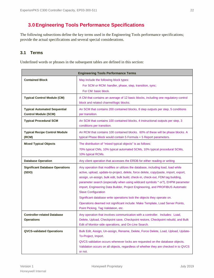
3.0 Engineering Tools Performance Specifications
The following subsections define the key terms used in the Engineering Tools performance specifications; provide the actual specifications and several special considerations.
3.1 Terms
Underlined words or phrases in the subsequent tables are defined in this section:
Engineering Tools Performance Terms
Contained Block May include the following block types:
For SCM or RCM: handler, phase, step, transition, sync;
For CM: basic block.
Typical Control Module (CM) A CM that contains an average of 12 basic blocks, including one regulatory control block and related channel/logic blocks.
Typical Automated Sequential Control Module (SCM)
An SCM that contains 200 contained blocks, 8 step outputs per step, 5 conditions per transition.
Typical Procedural SCM An SCM that contains 100 contained blocks, 4 instructional outputs per step, 3 conditions per transition.
Typical Recipe Control Module (RCM)
An RCM that contains 100 contained blocks. 60% of these will be phase blocks. A typical Phase Block would contain 5 Formula + 5 Report parameters.
Mixed Typical Objects The distribution of "mixed typical objects” is as follows:
70% typical CMs, 10% typical automated SCMs, 10% typical procedural SCMs, 10% typical RCMs.
Database Operation Any client operation that accesses the ERDB for either reading or writing
Significant Database Operations (SDO)
Any operation that modifies or utilizes the database, including load, load while active, upload, update-to-project, delete, force delete, copy/paste, import, export, assign, un-assign, bulk edit, bulk build, check-in, check-out, FDM tag building, parameter search (especially when using wildcard symbols * or?), EHPM parameter import, Engineering Data Builder, Project Engineering, and PROFIBUS Automatic Slave Configuration
Significant database write operations lock the objects they operate on.
Operations deemed not significant include: Make Template, Load Server Points, Point Picking, Tag Validation, etc.
Controller-related Database Operations
Any operation that involves communication with a controller. Includes: Load, Delete, Upload, Checkpoint save, Checkpoint restore, Checkpoint rebuild, and Bulk Edit of Monitor-side operations, and On-Line Search.
QVCS-validated Operations Bulk Edit, Assign, Un-assign, Rename, Delete, Force Delete, Load, Upload, Update-To-Project, Import.
QVCS validation occurs whenever locks are requested on the database objects. Validation occurs on all objects, regardless of whether they are checked in to QVCS or not.

ExperionPKS C300 Controller Capacity, EP03-300-511 23
Version 1 Honeywell Proprietary July 2019 Honeywell Internal
Tagged Object Any object that can be referenced as a point from the operational displays.
Client Enterprise Model Builder, Control Builder, FDM Tag Builder, Applications using the Config API interface (the interface is not externally available; only Honeywell applications can use the Config API)
Typical Engineering Repository Database Size
A typical Engineering Repository database may contain Maximum number of 30000 Mixed Typical Objects
3.2 Tools Performance Specifications
A clean start of Control Builder is assumed for all the following specifications. Continued use of a single Control Builder process instance for significant database operations results in a buildup of memory allocated to the Control Builder process. Periodic closing and re-starting of the Control Builder application are recommended to minimize the effects of the buildup in memory usage. The concerns noted above for Control Builder also apply to applications using the Config API interface.
Engineering Tools Performance Specifications
Rule # Description Limit
1 Maximum number of tagged objects for which database operations can be performed, when more than one client is in use up to the maximum number of clients allowed. 6
100
2 Maximum number of typical CMs for which database operations can be performed, when one client is in use, with exceptions noted below.
1000
2.1 Maximum number of typical automated SCMs, typical procedural SCMs, or typical RCMs for which database operations can be performed, when one client is in use, with exceptions noted below.
100
3 Maximum time to complete significant database operations performed on 100 typical CMs 6 20 minutes
4 Maximum time to complete significant database operations performed on 100 mixed typical objects
110 minutes
5 Additional time required for QVCS-validated operations to be performed when the tagged objects are under QVCS management
10%
6 Maximum number of Control Builder clients that can be supported and licensed per cluster 12
7 Maximum number of clients that can simultaneously perform significant database operations with execution time increases linearly with each additional client. 7
6
8 Maximum number of clients that can simultaneously perform significant database operations with no execution time guaranteed. 7
8
9 Maximum time to complete template propagation for 100 objects (typical CMs, typical automated SCMs, typical procedural SCMs, or typical RCMs)
60 minutes
10 Maximum number of clients that can perform controller-related database operations on the same controller at the same time 1,2
1
11 Maximum number of mixed typical objects exported or imported in a single operation3 25,000
12 Maximum time to complete an import of 700 mixed typical objects, using only one client 3 180 minutes
ExperionPKS C300 Controller Capacity, EP03-300-511 24
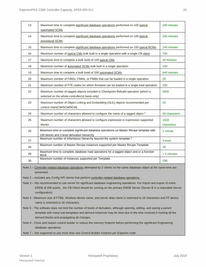
Version 1 Honeywell Proprietary July 2019 Honeywell Internal
13 Maximum time to complete significant database operations performed on 100 typical automated SCMs
240 minutes
14 Maximum time to complete significant database operations performed on 100 typical procedural SCMs
240 minutes
15 Maximum time to complete significant database operations performed on 100 typical RCMs 240 minutes
16 Maximum number of typical CMs bulk built in a single operation with a single CB client. 700
17 Maximum time to complete a bulk build of 100 typical CMs 40 minutes
18 Maximum number of automated SCMs bulk built in a single operation 100
19 Maximum time to complete a bulk build of 100 automated SCMs 640 minutes
20 Maximum number of FIM2s, FIM4s, or FIM8s that can be loaded in a single operation 25
21 Maximum number of FTE nodes for which firmware can be loaded in a single load operation 100
22 Maximum number of tagged objects included in Checkpoint Rebuild operation (which is selected on the whole controller(s) basis only)
5000
23 Maximum number of Object Linking and Embedding (OLE) objects recommended per control chart(CM/SCM/RCM)
20
24 Maximum number of characters allowed to configure the name of a tagged object 4 40 characters
25 Maximum number of characters allowed to configure expression in expression supported blocks
1024 characters
26 Maximum time to complete significant database operations on Master Recipe template with 100 blocks and 3 level derivation hierarchy
1 minute
27 Maximum number of inheritance hierarchy beyond the system template 5
3 level
28 Maximum number of Master Recipe instances supported per Master Recipe Template 20
29 Maximum time to complete database read operations for a tagged object and or a function block < 2 minutes
30 Maximum number of instances supported per Template 200
Note 1 – Controller-related database operations attempted by 2 clients on the same database object at the same time are prevented.
Note 2 – Includes any Config API clients that perform controller-related database operations.
Note 3 – Not recommended to use server for significant database engineering operations. For import and export of entire ERDB of 25K points , the CB Client should be running on the primary ERDB Server (Server B in a redundant Server configuration)
Note 4 - Maximum size of FTEB, Wireless device name, and server alias name is restricted to 16 characters and FF device name is restricted to 32 characters.
Note 5 - The software does not limit the number of levels of derivation, although opening, editing, and saving a parent template with many sub-templates and derived instances may be slow due to the time involved in locking all the derived blocks and propagating all changes.
Note 6 - Close and reopen control builder to reduce the memory footprint before performing the significant Engineering database operations
Note 7 – Not supported to use more than one Control Builder instance per Experion node

ExperionPKS C300 Controller Capacity, EP03-300-511 25
Version 1 Honeywell Proprietary July 2019 Honeywell Internal
4.0 C300 I/O Capacities
C300 IO Capacity Table
50 ms CEE 20ms CEE
Maximum Number of IO UNITS per C3001,2,4 64 (See Note 4)
80 (if using PM IOPs/Series C
IOMs only)
12
Maximum Number of IO UNITS per C300 IO Link 40 64
SERIES A IO-RELATED ONLY: Not Supported
Maximum Number of Series A IO Chassis connected through FTEB per C300 83 NA
Maximum Number of IO UNITS per Series A IO Chassis/FTEB 16 NA
Maximum Number of Serial Interface Modules per C300 3 NA
Maximum Number of Serial Interface Modules per FTEB 1 NA
Maximum Number of DeviceNet Modules per C300 12 NA
Maximum Number of DeviceNet Modules per FTEB 4 NA
Maximum Number of SST Profibus Modules per C300 10 NA
Maximum Number of SST Profibus Modules per FTEB 4 NA
FF FIM4-RELATED ONLY: Not Supported
Maximum number of Redundant or Non-Red FIM4s per C3001 15 NA
Maximum number of Redundant or Non-Red FIM8s per C3001 8 NA
PGM2-RELATED ONLY: Not Supported
Maximum number of Redundant or Non-Red PGM2 per C3001 4 NA
Note 1 – See Section 4.1.1 IO UNIT Definition Table for detail IO Units for each IO type supported.
Note 2 – Specific IO Devices may be further limited as described elsewhere due to Link Units or IO Buffer limits or other constraints
Note 3 – Because the FTEB has to connect to the same Control Firewall as the C300, this may be further limited by the number of available ports on the Control Firewall
Note 4 – Normal C300 50ms IO Limit is 64 IOUs with any combination of Series C (IOMs, FIMs, PGMs), Series A, and PM IOPs. If using PM IOPS or Series C IOMs only, the limit is extended to 80 IOUs (IOPs).
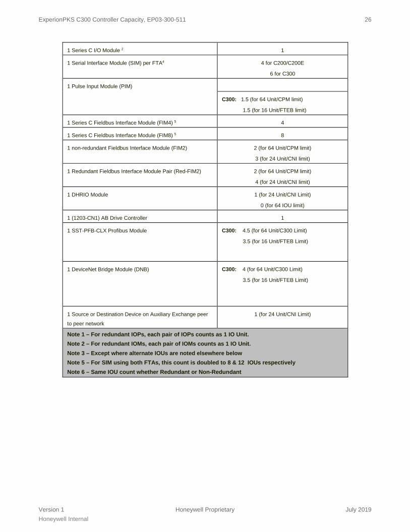
4.1 IO UNIT Definition Table
The following Table defines the IO UNIT load factor for the various I/O Devices supported by the C200, C200E, and C300:
I/O UNIT Definition Table
IO Device or Module IO Units
1 PM IOP Module 1 1
ExperionPKS C300 Controller Capacity, EP03-300-511 26
Version 1 Honeywell Proprietary July 2019 Honeywell Internal
1 Series C I/O Module 2 1
1 Serial Interface Module (SIM) per FTA4
4 for C200/C200E
6 for C300
1 Pulse Input Module (PIM)
C300: 1.5 (for 64 Unit/CPM limit)
1.5 (for 16 Unit/FTEB limit)
1 Series C Fieldbus Interface Module (FIM4) 5 4
1 Series C Fieldbus Interface Module (FIM8) 5 8
1 non-redundant Fieldbus Interface Module (FIM2) 2 (for 64 Unit/CPM limit)
3 (for 24 Unit/CNI limit)
1 Redundant Fieldbus Interface Module Pair (Red-FIM2) 2 (for 64 Unit/CPM limit)
4 (for 24 Unit/CNI limit)
1 DHRIO Module 1 (for 24 Unit/CNI Limit)
0 (for 64 IOU limit)
1 (1203-CN1) AB Drive Controller 1
1 SST-PFB-CLX Profibus Module
C300: 4.5 (for 64 Unit/C300 Limit)
3.5 (for 16 Unit/FTEB Limit)
1 DeviceNet Bridge Module (DNB)
C300: 4 (for 64 Unit/C300 Limit)
3.5 (for 16 Unit/FTEB Limit)
1 Source or Destination Device on Auxiliary Exchange peer
to peer network
1 (for 24 Unit/CNI Limit)
Note 1 – For redundant IOPs, each pair of IOPs counts as 1 IO Unit. Note 2 – For redundant IOMs, each pair of IOMs counts as 1 IO Unit. Note 3 – Except where alternate IOUs are noted elsewhere below Note 5 – For SIM using both FTAs, this count is doubled to 8 & 12 IOUs respectively Note 6 – Same IOU count whether Redundant or Non-Redundant

ExperionPKS C300 Controller Capacity, EP03-300-511 27
Version 1 Honeywell Proprietary July 2019 Honeywell Internal
For more information To learn more about Honeywell’s products or solutions visit our website www.honeywellprocess.com or contact your Honeywell account manager. Automation & Control Solutions Process Solutions Honeywell 1250 West Sam Houston Parkway South Houston, TX 77042 Honeywell House, Arlington Business Park, Bracknell, Berkshire, England RG12 1EB UK Shanghai City Centre, 100 Junyi Road Shanghai, China 20051 www.honeywellprocess.com
EP03-300-511 July 2019 © 2017 Honeywell International Inc.
Experion® is a registered trademark of Honeywell International Inc.
All other products and brand names shown are trademarks of their respective owners.
This document contains Honeywell proprietary information. It is published for the sole usage of Honeywell Process Solutions’
customers and prospective customers worldwide. Information contained herein is to be used solely for the purpose submitted, and
no part of this document or its contents shall be reproduced, published, or disclosed to a third party without the express
permission of Honeywell International Inc.
While this information is presented in good faith and believed to be accurate, Honeywell disclaims the implied warranties of
merchantability and fitness for a particular purpose and makes no express warranties except as may be stated in its written
agreement with and for its customer.
In no event is Honeywell liable to anyone for any indirect, special or consequential damages. The information and specifications in
this document are subject to change without notice.