expert system for detecting and diagnosing car engine ...ljs.academicdirect.org/a27/041_062.pdf ·...
TRANSCRIPT

Leonardo Journal of Sciences
ISSN 1583-0233
Issue 27, July-December 2015
p. 41-62
41
http://ljs.academicdirect.org/
Expert system for detecting and diagnosing car engine starter cranks fault
using dynamic control system
David Ibitayo LANLEGE*, Umar Muhammad GARBA, Usman Mohammed GANA,
Abdulrahman ABDULGANIYU
Department of Mathematics/Computer Science, Ibrahim Badamasi Babangida University
Lapai-Niger State, Nigeria
Email: [email protected]
* Corresponding author, phone: +2348030528667, 08156073449
Abstract
Application of Dynamic Control Systems (DCS) in detecting and
diagnosing car engine Starter Cranks is continuously being implemented to
serve different cases of real life problems such as Control of MEMS-based
scanning-probe data-storage devices, track-follow control for tape storage,
probe-based ultrahigh-density storage technology, a review of feed forward
control approaches in nanopositioning for high-speed SPM and so on. Car
engine Starter Cranks faults can be detected by sequence of diagnostic
processes which brings about the deployment of an Expert System. An Expert
System is one of the leading Artificial Intelligence techniques that have been
adopted to handle such task. This paper presents the imperatives for an Expert
System in developing Dynamic Control Systems for detecting and diagnosing
car engine Starter Crank faults through input and output requirements of
constructing successful Knowledge-Based Systems. Furthermore, diagnosis of
car engine Starter Cranks faults requires high technical skills and experience.
thus, DCS provides input and output equations in form of Matrix/Vector State
Space Representation (MSSR) which is useful in assisting mechanics for car
engine Starter Cranks fault detection and diagnosis via DCS and mathematical
Differential Equations (DE’s).
Expert system for detecting and diagnosing car engine starter cranks fault using dynamic control system
David I. LANLEGE, Umar M. GARBA, Usman M. GANA, Abdulrahman ABDULGANIYU
42
Keywords
Starter Cranks; Differential Equations; Matrix/Vector State Space
Representation (MSSR); Dynamic Control Systems (DCS); Expert System;
Generating Function; Equations (input, ourput, state)
Introduction
The definition of an ES (expert system) as proposed by [1] is: “an intelligent computer
program that uses knowledge and inference procedures to solve problems that are difficult
enough to require significant human expertise for their solution”. The ES is a knowledge-
based system that consists of two main modules: the knowledge base and the inference
engine. It usually has a knowledge acquisition module and an explanation module as extra
components. Systems that utilize the knowledge base approach are more straightforward than
the conventional approach. Knowledge is represented explicitly in the knowledge base so that
it can be altered with relative ease. This representation often takes the form of rules. The
inference engine utilizes the knowledge base contents to solve a particular problem according
to the user responses through an interface (e.g. enter the symptoms of the car fault). ES
provide powerful and flexible means for obtaining solutions to a variety of problems that
often cannot be dealt with by other, more traditional and orthodox methods. The terms expert
system and knowledge-based system (KBS) are often used synonymously. The four main
components of KBS are: a knowledge base, an inference engine, a knowledge engineering
tool, and a specific user interface. Some of KBS important applications include the following:
medical treatment, engineering failure analysis, decision support, knowledge representation,
climate forecasting, decision making and learning, and chemical process control [1,2]. An
expert system may completely fulfil a function that normally requires human expertise, or it
may play the role of assistance to a human decision maker. The decision maker may be an
expert in his own right, in which case the program may justify its existence by improving his
productivity [3]. Knowledge acquisition is the transfer and transformation of potential
problem-solving expertise from some knowledge source to a program. Knowledge
representation is a substantial subfield I its own right, which shares many concerns with both
formal philosophy and cognitive psychology. It is concerned with the ways in which

Leonardo Journal of Sciences
ISSN 1583-0233
Issue 27, July-December 2015
p. 41-62
43
information might be stored an associated in the human brain, usually from a logical, rather
than a biological, perspective. An expert system can be distinguished from a more
conventional application program in such a way that it stimulates human reasoning about a
problem domain, rather than simulating the domain itself. It performs reasoning over
representations of human knowledge, in addition to doing numerical calculations or data
retrieval. The knowledge base is structured as a set of objects, with rules relating them to
corresponding attributes. An object is the conclusion that is defined by its associated rules,
while an attribute is a specific quality that with its rule helps define the object. The rule that is
applied to an attribute states that an object either has or has not that attribute. These rules
occur in sequences and are expression of the form [3]:
If < conditions >, then < actions >If the conditions are true then, the actions are
executed.
Or: while values for attributes remain to be input / read value and assign to attribute /
evaluate conditions / fire rules whose conditions are satisfied.
When rules are examined by the inference engine, actions are executed if the
information supplied by the user satisfies the conditions in the rules. Conditions are
expressions involving attribute and logical connective ‘and’. The rule-based expert systems
have a wide range of applications for diagnostic tasks where expertise and experience are
available but deep understanding of the physical properties of the system is either unavailable
or too costly to obtain. In the rule based systems, knowledge is represented in the form of
production rules [3].
Inference engine
In order to execute a rule-based expert system using the method of forward chaining
we merely need to fire (or execute) actions whenever they appear on the action list of a rule
whose conditions are true [2,4]. This involves assigning values to attributes, evaluating
conditions, and checking to see if all of the conditions in a rule are satisfied. A general
algorithm for this is highlighted below:
while values for attributes remain to be input
read value and assign to attribute
evaluate conditions
fire rules whose conditions are satisfied
Several points about this require consideration. First, some conflict resolution strategy

Expert system for detecting and diagnosing car engine starter cranks fault using dynamic control system
David I. LANLEGE, Umar M. GARBA, Usman M. GANA, Abdulrahman ABDULGANIYU
44
needs to be employed in order to decide which rules are fired first. Our method is to fire the
rule which the system designer defined first. Also, we wish to cut down on computational
time. To do this we must not do anything which does not absolutely need to be done. This
means that conditions are only evaluated at the time they might change and that rules are
checked (to see if all of their conditions are satisfied) only when they might be ready to be
fired, not before. We shall do this as attributes are assigned values and shall only consider
rules and conditions affected by the new attribute assignment [4].
Working memory
Specific information on a current problem is represented as case facts and entered in
the expert system's working memory. The 'working memory contains both the facts
entered by the user from questions asked by the expert system, and facts inferred by the
system. The working memory could also acquire information from databases, spreadsheets, or
sensors, and be used by the expert system to conclude additional information about the
problem by using the general knowledge contained in the knowledge base [4].
Explanation facility
Besides providing final results or conclusions, both human experts and expert systems
can explain how they arrived at their results. This capability is often important because the
types of problems to which expert systems are applied require that a justification of the results
be provided to the user. For example, an expert system which recommends some antibiotic
treatment for a patient would need to explain to the physician how this recommendation was
formulated [4]. Expert systems also have the capability of explaining why a given question is
being asked. When an individual consults with a human expert, the conversation is highly
interactive, and on occasion, the individual may ask why a certain line of reasoning is being
pursued. The explanation given can make the user feel more comfortable with the line of
questioning and also help to clarify what issues the expert believes are important for the
problem [4].
User interface
The user interface is the means of communication between a user and the expert
systems problem-solving processes. A good expert system should have an efficient interface.

Leonardo Journal of Sciences
ISSN 1583-0233
Issue 27, July-December 2015
p. 41-62
45
The user interface in this system will be able to accept the instructions in a form that the user
enters and translate them into working instructions for rest of the system. The user will be
asked several questions which he would have to answer, subsequently a solution will be
displayed thereby. Careful attention should be given to the screen design in order to make the
expert system appear friendly to the user [5].
Expert system for diagnosing the failure of different machines
One of the earlier published references on diagnostic ES for technical fault diagnosis
was developed at MIT in the early 1970’s as stated by Scherer and White in 1989 [6]. Some
researches that utilize the expert system for the purpose of diagnosing the failure of different
machines are reviewed in the following paragraphs below: Kadarsah proposed and designed a
decision model for car fault diagnosis in which an ES was utilized to help inexperienced
mechanics and drivers [6]. The model consists of inference engine, knowledge base, database,
user interaction and adaptive mechanism. The Inference engine uses backward chaining as a
result of a small number of outputs with many possible inputs. In addition, the adaptive
mechanism was utilized in the user interaction section in order to receive feedback about
system diagnosis result. The feedback results were stored in a database. The adaptive system
then processes the stored data and extracts additional rules with the goal of improving the
knowledge base. In this system, car faults are divided into three states: Start-up state, Run-
stable state and Movement-state. Shell Rule based expert system (CLIPS) with forward
chaining inference engine is used in the implementation. CLIPS store’s the knowledge in
rules form, which has logic-based representation as well as the production rules. The system
interacts with the user through an interface and gives the diagnosis result with illustration.
The rule-based expert system contains 150 rules for car failure causes. However,
improvement in the domain knowledge and applying adaptive technique for knowledge
creation are required in such system [6]. In the work of Peter Nabende and Tom Wanyama,
Heavy Duty Diesel Engines (HDDEs) diagnosis was proposed. HDDEs maintenance requires
high technical skills and extensive experienced mechanics which are scarce. As a result,
employing an expert system in such domain can be highly useful. The HDDE faults diagnosis
ES was able to successfully detect malfunctions in the engines and give recommendation of
corrective actions. System development leads to collection of valuable information related to
HDDE fault diagnosis and training. However, updating the knowledge base affects the

Expert system for detecting and diagnosing car engine starter cranks fault using dynamic control system
David I. LANLEGE, Umar M. GARBA, Usman M. GANA, Abdulrahman ABDULGANIYU
46
reasoning process performance especially in the continuous run [6]. A research was done by
Jindal et al. to assist in the design of an ES for car failure diagnosis and repair [6]. Many
factors were considered in this research such as the required time, the place and human
expertise level. In addition, the ES development was accompanied by reviewing the
technologies used in designing such systems to achieve the best means to be followed.
However, the proposed prototype was not promoted to be used as a complete application due
to time and resources limitations. Thus, adopting new rules to be performed was an example
of further enhancements that the system needed. A survey was done by Milanović et al. for
developing moto cultivator fault diagnosis model. This model is based on the hybridization of
Expert System (ES) and Decision Support System (DSS) in which ES outcome represents the
input to the DSS. The supplier selection for faulty component replacement is made by DSS
based on ES outcome. In practice, the designed hybrid system was applied in a small moto
cultivator importer and distributor company for servicing purposes. It has proved to be a very
useful tool for equipment servicing needs with low development cost. It increases the
efficiency of labour and workers ‘satisfaction [6].
Conventional programs versus expert systems
According to Durkin [4,7], it is important to understand and appreciate the differences
between conventional computer programs and knowledge processing or expert
systems.Knowledge processing represents an evolution, rather than a revolution, in the way
individuals and computers interact to solve problems. The most basic difference between the
two is that conventional programs process data, while expert systems process knowledge.
This basic difference influences both the nature of the processing technique used and the
results obtained. Conventional programs process data which is usually in numeric form, while
an expert system works with symbolic information. Data are isolated bits of information about
a problem, whereas symbolic information represents statements or facts concerning the
problem which can be used with general knowledge to infer new information. Conventional
programs process data by means of algorithms, whereas an expert system will use heuristic
reasoning techniques. An algorithm represents a finite set of well-defined steps to be
performed. Heuristic reasoning works with the available information to draw conclusions
about the problem, but does not follow a prescribed sequence of steps. A conventional
program requires complete and precise information. An expert system can work with the

Leonardo Journal of Sciences
ISSN 1583-0233
Issue 27, July-December 2015
p. 41-62
47
available information whether it is incomplete or uncertain. In this sense, an expert system
can provide some results even under the constraints of limited or uncertain information. A
conventional program would be severely limited under such constraints. The interface of an
expert system permits questions to be asked and answers given using a natural language style.
This interface is more readily accepted by end-users than the command interface found with
most conventional programs. Interaction with an expert system also follows more closely the
conversation between one human obtaining advices from another human. During the
conversation, explanations are provided by the expert to queries as to "why" a question is
being asked, and "how" a given conclusion was reached. This point makes an expert system
considerably different from a conventional program, which simply provides a final answer.
Conventional programs provide a final solution usually in the form of a result from a
computation. The computation may have involved a complex series of tasks, but the user will
only see the final result and not the intermediate steps that led to the final result. Expert
systems provide a result in the form of a recommendation, with a justification in the form of a
tracing of its reasoning. Given the correct information, conventional programs will provide an
exact solution to a problem. It is an "all or nothing" situation. Expert systems can make
mistakes, just as a human expert might. This point appears to give the conventional program
an advantage over the expert system. However, this appearance is only an illusion. Expert
systems work on types of problems which are less structured than conventional programs, and
the information available may not be sufficient to obtain an exact solution. However, the
expert system will still be able to reach some reasonable conclusion, even if it is not optimal,
whereas a conventional program will fail if not provided with all of the information it needs.
This ability of an expert system to be able to make decisions in the absence of complete or
certain information is the result of developments in the area of inexact reasoning.
Why use an expert system?
Like any project venture, developing an expert system must have some justification
[4,5]. Insight for justifying an expert system can be gained when one compares an expert
system with a human expert. One can formulate several general reasons for employing an
expert system such as: replacement of human expert, assistant to human expert, transfer of
expertise to novice [4]. Using an expert system to replace a human expert is done primarily to
use the system when the expert is not available. For example, through time constraints, the
Expert system for detecting and diagnosing car engine starter cranks fault using dynamic control system
David I. LANLEGE, Umar M. GARBA, Usman M. GANA, Abdulrahman ABDULGANIYU
48
human expert may not be available, while an expert system designed to control some
manufacturing process would be available 24 hours a day. Another expert system, containing
the expertise of a unique expert within a company, could be made available to company sites
located in other geographic areas. If the expert should leave or retire from the company, the
expertise captured in the expert system could serve as a replacement for the expert. Human
experts may be scarce, hence expensive. Expert systems, by contrast, may be inexpensive.
Developing an expert system can be a costly venture, but the finished product would have low
operating costs. The finished system can also be duplicated at low cost and distributed widely
[4,5]. In the area of science, justifying an expert system for replacing a human can be found in
such applications as space exploration [4], or providing the expertise of a geophysicist to
some remote oil exploration site [4]. Another example would be to replace the human
operator of a control process. Assisting a human expert is one of the most commonly found
applications of expert systems. In this application, the expert system attempts to aid the
human expert in a routine or mundane task. For example, a physician may have general
knowledge of most diseases, but could use some additional support in diagnosing a given
problem with a patient. In another example, a bank manager may be responsible for
processing numerous loan applications, but could use help with some of the routine decisions
made. In both applications, the human expert is fully capable of performing the task, but
obtains additional support from the expert system. In this type of expert system application,
the objective is to improve the overall productivity of the current practice. One specialized
application of an expert system which can be used to assist the expert is the ability of the
expert system to learn about a specific problem. The most common learning method used in
expert systems today is a technique known as induction [4,7]. The induction technique works
with information contained in a set of examples to induce a set of rules which capture the
knowledge about the problem. This approach has particular value for those problems where
the expert lacks the knowledge to form decisions, but has a history of data on the problem.
The induction technique can uncover classifications in the data which can be used for guiding
the decision process. The expertise held by a human expert is a valuable resource. Knowledge
is gained by the expert through years of experience from working on the problem. In many
organizations, it is important that this expertise not be lost, but transferred to others through
training. An expert system can be developed to accomplish this training task.

Leonardo Journal of Sciences
ISSN 1583-0233
Issue 27, July-December 2015
p. 41-62
49
Material and method
Dynamics Control System (DCS)
In applied mathematics and engineering the central theory deals with the behaviour of
dynamical system over time. The dynamic behaviour of a system may therefore be understood
by studying their mathematical description. For instance, the flight path of an airplane subject
to certain engine thrust, rudder elevation angles and particular wind condition or the current
flowing in an electrical circuit consisting of interconnections of resistors, inductors,
capacitors, transistors, diodes, voltage or current source etc can be predicted using
mathematical description of the pertinent behaviour. Mathematical equations in the form of
Differential or difference equations are used to describe the behaviour of the process usually
referred to governing equations whose solutions give the required response of the particular
system under consideration.
A system is a group of component part put together to accomplish a certain task. It is
also said to be an arrangement or collection of things connected or related in such a manner as
to form an entire whole. Simply, a system is an arrangement of physical component connected
or related in such a manner as to form and or act an entire unit. Whereas the concept of
Control is analogous as either to direct, regulate or to command. Thus; a Control System is an
arrangement of physical components connected or related in such a manner as to command,
direct and regulate itself or another system. It is therefore important to note that a control
system is made up of three components namely; input, process and output
Mathematical classification of systems
In this paper we shall not dwell on a comprehensive classification of systems as this
may not give the much desired understanding of the concept. Hence an enumeration of the
more common classes of systems most often encountered in field of engineering and science
is of high consideration. Any particular set of equation describing a given system generally
depends on the effect to be captured. Some of these systems may include Lumped Parameter
or Finite-Dimensional Systems; Distributed Parameters or infinite – Dimensional Systems;
Continuous- Time and discrete – Time Systems; Deterministic and Stochastic Systems and
appropriate combination of any of the fore mentioned is known as hybrid systems. It must
however be noted that the appropriate mathematical setting for Finite–Dimensional System
are Finite-Dimensional Vector Spaces and for infinite–Dimensional system are defined
Expert system for detecting and diagnosing car engine starter cranks fault using dynamic control system
David I. LANLEGE, Umar M. GARBA, Usman M. GANA, Abdulrahman ABDULGANIYU
50
Infinite Dimensional Linear Spaces. Continuous–Time Finite–Dimensional Systems are
described by Ordinary Differential Equations or some kinds of integral Equations while
Discrete-Time Finite Dimensional Systems are governed by Ordinary Difference equations or
Discrete-Time Counterparts to those Integral equations. The governing differential equations
to Infinite–Dimensional Systems include partial Differential equations Volterra intergro-
Differential Equations, Functional Equations etc.
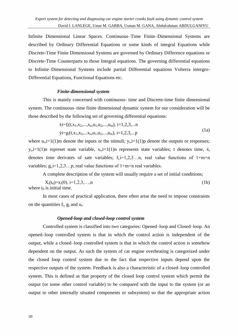
Finite-dimensional system
This is mainly concerned with continuous- time and Discrete-time finite dimensional
system. The continuous–time finite dimensional dynamic system for our consideration will be
those described by the following set of governing differential equations:
ẋi=fi(t,x1,x2,...,xn,u1,u2,...,um), i=1,2,3,...n
ẏi=gi(t,x1,x2,...xn,u1,u2,...,um), i=1,2,3,...p (1a)
where ui,i=1(1)m denote the inputs or the stimuli; yi,i=1(1)p denote the outputs or responses;
yi,i=1(1)n represet state variable, xi,i=1(1)n represents state variables; t denotes time, ẋi
denotes time derivates of sate variables; fi,i=1,2,3…n, real value functions of 1+m+n
variables; gi,i=1,2,3…p, real value functions of 1+m+n real variables.
A complete description of the system will usually require a set of initial conditions;
Xi(t0)=xi(0), i=1,2,3,…,n (1b)
where t0 is initial time.
In most cases of practical application, there often arise the need to impose constraints
on the quantities fi, gi and ui.
Opened-loop and closed-loop control system
Controlled system is classified into two categories: Opened–loop and Closed–loop. An
opened–loop controlled system is that in which the control action is independent of the
output, while a closed–loop controlled system is that in which the control action is somehow
dependent on the output. As such the system of car engine overheating is categorized under
the closed loop control system due to the fact that respective inputs depend upon the
respective outputs of the system. Feedback is also a characteristic of a closed–loop controlled
system. This is defined as that property of the closed loop control system which permit the
output (or some other control variable) to be compared with the input to the system (or an
output to other internally situated components or subsystem) so that the appropriate action

Leonardo Journal of Sciences
ISSN 1583-0233
Issue 27, July-December 2015
p. 41-62
51
may be formed as some function of the output and input. Some of the characteristics of
feedback include increases accuracy oscillation, tendency towards instability, reduces the
sensitivity of ratio output to variation in system parameters, reduces effect of nonlinearity,
reduces the effect of external disturbance or noise, increases bandwidth.
For a given set of differential equations describing a certain dynamic system (system
that changes with time) there is need to know the set of state variables and there number in the
system. That is: How many state variables are involved? What are these state variables?
For the first, the number of state variables is equal to the total number of initial
conditions required to completely solve the differential equations of overheating for a car
engine. For instance, if a dynamic system is described by a single second order differential
equation then two initial conditions is required to completely solve the differential equation.
Thus there are two state variables for this system. For (ii); these variables for which initial
conditions are required for the solution of the governing differential equation defined above
are chosen as the required state variable
General formulation
Once the state variables are appropriately selected the next step is to construct the state
variable equations. These state equations are system of first order differential equations in the
state variables on the left hand side and algebraic system (function) of the state variables as
system input and possibly time on the right hand side. In general for a multi- input multi-
output system with m state variables we have
X1.x2.x3,….,xm p inputs u1,u2,u3…up and r outputs.
Y1,y2,y3,…,yr the state variable equations are given in this form :
tuuuxxxfx
tuuuxxxfx
tuuuxxxfx
tuuuxxxfx
pmmm
pm
pm
pm
,,...,,,...,
,,...,,,...,
,,...,,,...,
,,...,,,...,
2121
212133
212122
212111
(1c)
where fi are in general non linear functions of the arguments.
Similarly, the system output variables may also be expressed as follows:
Expert system for detecting and diagnosing car engine starter cranks fault using dynamic control system
David I. LANLEGE, Umar M. GARBA, Usman M. GANA, Abdulrahman ABDULGANIYU
52
tuuuxxxgy
tuuuxxxgy
tuuuxxxgy
pm
pm
pmi
,,...,,,...,
,,...,,,...,
,,...,,,...,
212133
212122
21211
(2)
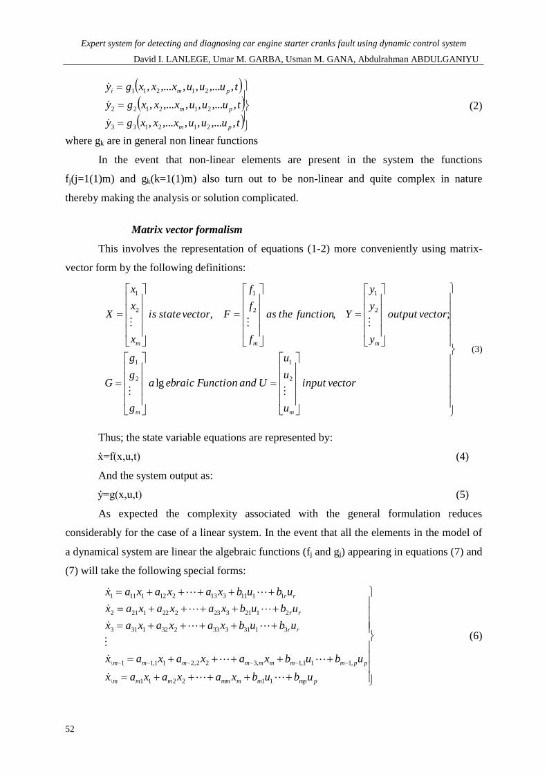
where gk are in general non linear functions
In the event that non-linear elements are present in the system the functions
fj(j=1(1)m) and gk(k=1(1)m) also turn out to be non-linear and quite complex in nature
thereby making the analysis or solution complicated.
Matrix vector formalism
This involves the representation of equations (1-2) more conveniently using matrix-
vector form by the following definitions:
vectorinput
u
u
u
UandFunctionebraica
g
g
g
G
vectoroutput
y
y
y
Yfunctiontheas
f
f
f
Fvectorstateis
x
x
x
X
mm
mmm
2
1
2
1
2
1
2
1
2
1
lg
;,,
(3)
Thus; the state variable equations are represented by:
ẋ=f(x,u,t) (4)
And the system output as:
ẏ=g(x,u,t) (5)
As expected the complexity associated with the general formulation reduces
considerably for the case of a linear system. In the event that all the elements in the model of
a dynamical system are linear the algebraic functions (fj and gj) appearing in equations (7) and
(7) will take the following special forms:
pmpmmmmmmm
ppmmmmmmmm
rr
rr
rr
ububxaxaxax
ububxaxaxax
ububxaxaxax
ububxaxaxax
ububxaxaxax
112211\
,111,1,322,211,11\
31313332321313
21213232221212
11113132121111
(6)
Leonardo Journal of Sciences
ISSN 1583-0233
Issue 27, July-December 2015
p. 41-62
53
prprrmmrrr
pprrrmmrrrr
ppmm
ppmm
ppmm
udududxcxcxcy
udududxcxcxcy
udududxcxcxcy
udududxcxcxcy
udududxcxcxcy
221132211
,122,111,1,122,211,11
323213132321311
222212122221212
121211112121111
(7)
By defining the following quantities to enable us represent the formulations above in
matrix-vector form:
matrixInput
bbb
bbb
bbb
BmatrixState
aaa
aaa
aaa
A
pm
mpmm
p
p
mm
mmmm
m
m
21
22221
11211
21
22221
11211
, (8)
pr
rprr
m
m
mr
rmrr
m
m
ddd
ddd
ddd
DMatrixOutput
ccc
ccc
ccc
C
21
22221
11211
21
22221
11211
, (9)
Therefore, the final form of the system in the matrix–vector form is given as:
Ẋ=AX+BU State Equation (10)
Ẏ=CX+DU Output Equation (11)
The above system of equation is known as the state-space representation or state –
space form of the system model. This very convenient form of representing a system model is
particularly useful in the analysis and control of a dynamic system.
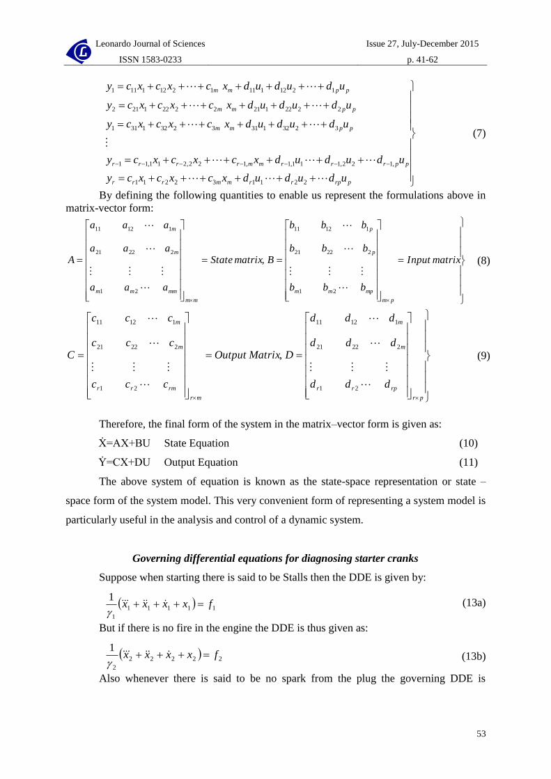
Governing differential equations for diagnosing starter cranks
Suppose when starting there is said to be Stalls then the DDE is given by:
11111
1
1fxxxx
(13a)
But if there is no fire in the engine the DDE is thus given as:
22222
2
1fxxxx
(13b)
Also whenever there is said to be no spark from the plug the governing DDE is
Expert system for detecting and diagnosing car engine starter cranks fault using dynamic control system
David I. LANLEGE, Umar M. GARBA, Usman M. GANA, Abdulrahman ABDULGANIYU
54
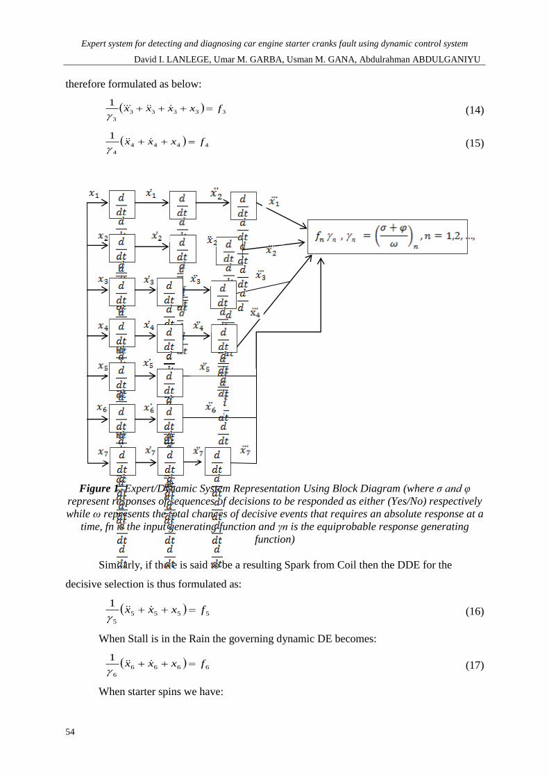
therefore formulated as below:
33333
3
1fxxxx
(14)
4444
4
1fxxx
(15)
Figure 1. Expert/Dynamic System Representation Using Block Diagram (where σ and φ
represent responses of sequences of decisions to be responded as either (Yes/No) respectively
while ω represents the total chances of decisive events that requires an absolute response at a
time, fn is the input generating function and γn is the equiprobable response generating
function)
Similarly, if there is said to be a resulting Spark from Coil then the DDE for the
decisive selection is thus formulated as:
5555
5
1fxxx
(16)
When Stall is in the Rain the governing dynamic DE becomes:
6666
6
1fxxx
(17)
When starter spins we have:
Leonardo Journal of Sciences
ISSN 1583-0233
Issue 27, July-December 2015
p. 41-62
55
877777
7
21
ffxxxx
(18)
By equating equations (12) and (14):
11111
1
1fxxxxie
(19)
33333
3
1fxxxx
(20)
Again by equating (13) and (17):
22222 fxxxxie (21)
6666
6
1fxxx
(22)
Similarly choosing equations (12) and (18):
11111
1
1fxxxxie
(23)
77777
7
1fxxxx
(24)
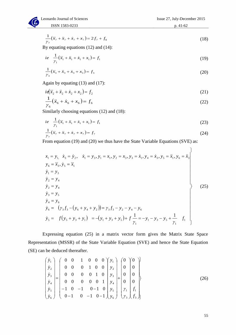
From equation (19) and (20) we thus have the State Variable Equations (SVE) as:
1
1
531
1
5311355
64233246336
64
53
42
42
31
1536
3615341332113123,11
11
,
,,,,,,,
fyyyfyyyyyyfy
yyyfyyyfy
yy
yy
yy
yy
yy
xyxy
xyxyxyxyxyxyyxyxyx
(25)
Expressing equation (25) in a matrix vector form gives the Matrix State Space
Representation (MSSR) of the State Variable Equation (SVE) and hence the State Equation
(SE) can be deduced thereafter.
3
1
3
1
6
5
4
3
2
1
6
5
4
3
2
1
0
0
0
0
0
0
0
0
101010
010101
100000
010000
001000
000100
f
f
y
y
y
y
y
y
y
y
y
y
y
y
(26)

Expert system for detecting and diagnosing car engine starter cranks fault using dynamic control system
David I. LANLEGE, Umar M. GARBA, Usman M. GANA, Abdulrahman ABDULGANIYU
56
Hence the State Equation (SE) for diagnosing start and running process becomes:
Ẏ=AZ+BF (27)
Using equation (21) and (22) to formulate another SVE as well as MSSR for the given
system for the described system to be decisively diagnosed. Thus; equation (28) below gives
SVE for the described system as :
However; from equation (21) and (22) we thus have the State Variable Equations
(SVE) formulated as:
22531221355
664266244
53
42
31
64252564236221 ,,,,,,
fzzzfzzzz
fzzfzzz
zz
zz
zz
xzxzxzxzxzxzxz
(28)
If equation (28) is expressed in a matrix vector form gives the Matrix State Space
Representation (MSSR) of the State Variable Equation (SVE) and hence the State Equation
(SE) can be deduced also thereafter.
2
6
2
6
5
4
3
2
1
5
4
3
2
1
0
0
0
0
0
0
0
10101
01010
10000
01000
00100
f
f
z
z
z
z
z
z
z
z
z
z
(29)
Hence, the State Equation (SE) for diagnosing running process becomes:
Z=AZ+BF (30)
Using equation (23) and (24) to formulate another SVE as well as MSSR for the given
described system to be decisively diagnosed. Thus; equation (31) below gives SVE for the
described system as:
772466
111355
64
53
42
31
1576761574137211 ,,,,,,
fqqqq
fqqqq
xqandxqxqxqxqxqxqxq
(31)

Leonardo Journal of Sciences
ISSN 1583-0233
Issue 27, July-December 2015
p. 41-62
57
)(0
0
0
0
101010
010101
100000
010000
001000
000100
7
1
6
5
4
3
2
1
6
5
4
3
2
1
tF
q
q
q
q
q
q
q
q
q
q
q
q
(32)
Again; the State Equation (SE) is given by equation (33) as:
Q=AQ+BF (33)
Practical Illustration of an Expert System using Dynamic Control System
Output Equations
From equation (30) suppose the input is say 1f (Starter Cranks?) i.e.:
Figure 2. A Test Interface for the Detection of Starter Cranks
Suppose the response is Yes; then the resulting output equation becomes:
2
6
5
4
3
2
1
120
0
0
0
,00000,,00001:;
FD
z
z
z
zz
yCieDGCI
zy
(34)
And the equivalence Expert System graphics output is:
Expert system for detecting and diagnosing car engine starter cranks fault using dynamic control system
David I. LANLEGE, Umar M. GARBA, Usman M. GANA, Abdulrahman ABDULGANIYU
58
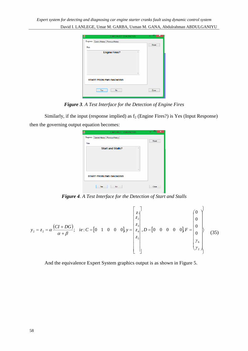
Figure 3. A Test Interface for the Detection of Engine Fires
Similarly, if the input (response implied) as f2 (Engine Fires?) is Yes (Input Response)
then the governing output equation becomes:
Figure 4. A Test Interface for the Detection of Start and Stalls
2
6
5
4
3
2
1
220
0
0
0
,00000,,00010:;
FD
z
z
z
zz
yCieDGCI
zy
(35)
And the equivalence Expert System graphics output is as shown in Figure 5.

Leonardo Journal of Sciences
ISSN 1583-0233
Issue 27, July-December 2015
p. 41-62
59
Figure 5. A Test Interface for the Detection of OBD/Blink Code
Again, if the input (response implied) is f3 (Check OBD, blink code?) and input
response is Yes from the interface in fig 4 then the governing output equation becomes:
2
6
5
4
3
2
1
330
0
0
0
,00000,,00100:;
FD
z
z
z
zz
yCieDGCI
zy (36)
And the equivalence Expert System graphics output is as shown in Fig 6.
Figure 6. A Test Interface for the Detection of Stalls on Key release
Also, if the input (response implied) is f4 (Stalls on key release to run?) and input
response is Yes then the governing output equation becomes:

Expert system for detecting and diagnosing car engine starter cranks fault using dynamic control system
David I. LANLEGE, Umar M. GARBA, Usman M. GANA, Abdulrahman ABDULGANIYU
60
2
6
5
4
3
2
1
440
0
0
0
,00000,,01000:;
FD
z
z
z
zz
yCieDGCI
zy
(37)
And the equivalence Expert System graphics output is as shown in Fig. 7.
Figure 7. A Test Interface for the Detection of Circuit/ Column key Switch Failure
Therefore; the suggested output gives the general solution of the problem as shown in
fig 7 for an ES and represented by equation (37) for the sequence of responses (Yes) for a
DCS. This is to say that the detected problem is ‘ignition “run” Circuit or column key switch
failure, Ring out with meter.
Discussion
It is very clear that throughout the illustrations of a DCS via an ES that DCS is such a
system that simply can sufficiently be used to fully represent the decisive situations of an ES.
In addition when considering the DDE formulated especially in equations (34-37) and the
equivalence interface representation of an ES which helps in the interpretation of the
formulated DDC especially to the world where the mathematical language becomes difficult
and complicated to the ordinary World’s interpretation. Also, the DDE’s considered in this
paper has established a ground through which every decisive system can be expressed through
DCS more effectively and in a logically systematic form.
According to another aspect of the present invention, the present invention provides a
Leonardo Journal of Sciences
ISSN 1583-0233
Issue 27, July-December 2015
p. 41-62
61
dynamical system for tracking a reference signal, including [9]: a controlled element for being
set according to a provided control signal; a controller for feedback controlling the controlled
element by providing the control signal, wherein the controller is adapted to feedback control
the controlled element depending on a provided reference signal and a feedback signal
indicating an actual state of the controlled element [10]; and an impulsive state modification
block for modifying an internal state of the controller at one or more discrete time instants,
while applying the control function at time periods not including the discrete time instants,
wherein the impulsive state modification block is adapted to modify the internal state
depending on a signal external to the controller [6,11].
However a DCS has a more logically and a mathematically established system that
uses concepts capable of handling any form of ES for a given sequence of decision making
especially as the type considered in the detection of Car engine tarter cranks fault .
The main objective is to express a dynamically formulated system of decisions
requiring responses as the case of a typical ES which has successfully been illustrated Using
the concept of DCS. It is then however said that the equation below gives a general stage
process of decision making for detecting car engine starter cranks fault by an ES using a
modelled DCS output general equation of the form:
matrixidentitynnCie
DHCEyhsayoutputinputgivenDUCEy
nn
nnn
:
;/,
(40)
4
1
5
4
3
2
1
0
0
0
0
,...3,2,1:00000,
HnEhyieD
E
E
E
E
EE
E nnn
n
(41)
Conclusively, for the given illustrations in Figures 2-7 is however important to say
that figure 7 gives the detected fault as ‘ignition “run” Circuit or column key switch failure,
Ring out with meter’’ and the equivalence solution given by equation (37) as obtained by
applying Dynamic Control System (DSC) approach.

Expert system for detecting and diagnosing car engine starter cranks fault using dynamic control system
David I. LANLEGE, Umar M. GARBA, Usman M. GANA, Abdulrahman ABDULGANIYU
62
References
1. Ahmad A. T., An Expert System for Car Failure DiagnosisWorld Academy of Science,
Engineering and Technology, 2007, 1, p. 445-458.
2. Albahari B., Drayton P., Brad Merrill, C#Essentials, 2nd
EditionUAS, O’Reilly Publisher,
ISBN: 0-596-00315-3.
3. Pantazi et al., Control of MEMS-based scanning-probe data-storage devices, IEEE Trans.
Control Syst. Technol, 2007, 15(5), p. 824-841.
4. Durkin J., Application of Expert Systems in the Sciences, Ohio Journal of Science, 1990,
90(5), p. 171-179.
5. Neeta V., Yash, J., Rashi A., Swati J., An Approach towards designing of Car
Troubleshooting Expert System. International Journal of Computer Applications, 2010,
1(23), p. 63-65.
6. Lee C., Salapaka S. M., Fast robust nanopositioning: A linear-matrix-inequalities-based
optimal control approach, IEEE/ASME Transactions on Mechatronics, 2009, 14(4), p.
414-422.
7. Morris, R., If it jams, fix it, if it breaks, fix it again, 2011, Retrieved 06/09/2014from
www.ifitjams.com.
8. Sebastian et al., Probe-based ultrahigh-density storage technology, IBM J. Res. Develop,
2008,52(4/5), p. 493-511.
9. Pantazi et al., Track-follow control for tape storage. Workshop on Dynamics and Control
of Micro and Nanoscale Systems IBM Research - Zurich,December, 2009,15(11),p.10-11.
10. Salama A., Mohd S., Mazin and Omar I., Implementing an Expert Diagnostic
Assistance System for Car Failureand Malfunction, International Journal of Computer
science Issues, 2012, 9(2), p. 1-7.
11. Widodo. B., The Development of an Expert Car Failure Diagnosis System with Bayesian
Approach. Journal of Computer Science, 2013, 9(10), p. 1383-1388 8.
12. Clayton et al., A review of feed forward control approaches in nanopositioning for high-
speed SPM. Trans. ASME, J. Dyn. Syst. Meas. Control, 2009,131(6), p.061101-1 -
061101-19.