explanation of adaptive platform design · explanation of adaptive platform design autosar ap...
TRANSCRIPT

Explanation of Adaptive Platform Design AUTOSAR AP Release 17-10
1 of 51 Document ID 706: AUTOSAR_EXP_PlatformDesign
- AUTOSAR Confidential -
Document Title Explanation of Adaptive Platform Design
Document Owner AUTOSAR
Document Responsibility AUTOSAR
Document Identification No 706
Document Status Final
Part of AUTOSAR Standard Adaptive Platform
Part of Standard Release 17-10
Document Change History Date Release Changed by Description
2017-10-27 17-10 AUTOSAR Release Management
Added RESTful Communication
2017-03-31 17-03 AUTOSAR Release Management
Initial release

Explanation of Adaptive Platform Design AUTOSAR AP Release 17-10
2 of 51 Document ID 706: AUTOSAR_EXP_PlatformDesign
- AUTOSAR Confidential -
Disclaimer This work (specification and/or software implementation) and the material contained in it, as released by AUTOSAR, is for the purpose of information only. AUTOSAR and the companies that have contributed to it shall not be liable for any use of the work. The material contained in this work is protected by copyright and other types of intellectual property rights. The commercial exploitation of the material contained in this work requires a license to such intellectual property rights. This work may be utilized or reproduced without any modification, in any form or by any means, for informational purposes only. For any other purpose, no part of the work may be utilized or reproduced, in any form or by any means, without permission in writing from the publisher. The work has been developed for automotive applications only. It has neither been developed, nor tested for non-automotive applications. The word AUTOSAR and the AUTOSAR logo are registered trademarks.

Explanation of Adaptive Platform Design AUTOSAR AP Release 17-10
3 of 51 Document ID 706: AUTOSAR_EXP_PlatformDesign
- AUTOSAR Confidential -
Table of Contents 1 Introduction to this document .............................................................................. 6
1.1 Contents ....................................................................................................... 6 1.2 Prereads ....................................................................................................... 6 1.3 Relationship to other AUTOSAR specifications ............................................ 6
2 Technical Scope and Approach ........................................................................... 7 2.1 Overview – landscape of intelligent ECUs .................................................... 7 2.2 Technology Drivers ...................................................................................... 7 2.3 Adaptive Platform – Characteristics ............................................................. 8
C++...................................................................................................................... 8
SOA ..................................................................................................................... 8
Parallel processing .............................................................................................. 9
Leveraging existing standard ............................................................................... 9 Safety and security .............................................................................................. 9 Planned dynamics ............................................................................................. 10 Agile .................................................................................................................. 10
2.4 Integration of Classic, Adaptive and Non-AUTOSAR ECUs ....................... 10 2.5 Scope of specification ................................................................................ 12
3 Architecture ....................................................................................................... 13
3.1 Logical view ................................................................................................ 13 ARA ................................................................................................................... 13
Language binding, C++ Standard Library, and POSIX API ............................... 14 Application launch and shutdown ...................................................................... 14 Application interactions ...................................................................................... 14
Non-standard interfaces .................................................................................... 15
3.2 Physical view .............................................................................................. 15 OS, processes, and threads .............................................................................. 15 Library-based or Service based Functional Cluster implementation .................. 16
Interaction between Functional Clusters ............................................................ 16 Machine/hardware ............................................................................................. 16
4 Methodology and Manifest ................................................................................ 18 4.1 Manifest ...................................................................................................... 18 4.2 Application Design ...................................................................................... 20
4.3 Application Manifest ................................................................................... 20 4.4 Service Instance Manifest .......................................................................... 21
4.5 Machine Manifest ....................................................................................... 21 5 Operating System .............................................................................................. 23
5.1 Overview .................................................................................................... 23 5.2 POSIX ........................................................................................................ 23 5.3 Scheduling ................................................................................................. 24 5.4 Memory management ................................................................................ 24 5.5 Device management .................................................................................. 24
6 Execution Management ..................................................................................... 25 6.1 Overview .................................................................................................... 25 6.2 System Startup ........................................................................................... 25 6.3 Execution Management Responsibilities .................................................... 25 6.4 State Management ..................................................................................... 26

Explanation of Adaptive Platform Design AUTOSAR AP Release 17-10
4 of 51 Document ID 706: AUTOSAR_EXP_PlatformDesign
- AUTOSAR Confidential -
7 Communication Management ............................................................................ 28 7.1 Overview .................................................................................................... 28 7.2 Service Oriented Communication ............................................................... 28
7.3 Language binding and Network binding ..................................................... 29 7.4 Generated Proxies and Skeletons of C++ Language Binding .................... 30 7.5 Static and dynamic configuration................................................................ 30
8 RESTful Communication ................................................................................... 32 8.1 Overview .................................................................................................... 32
8.2 Architecture ................................................................................................ 32 8.3 Components ............................................................................................... 33
9 Diagnostics ........................................................................................................ 34
9.1 Overview .................................................................................................... 34 9.2 Diagnostic communication sub-cluster ....................................................... 34 9.3 Event memory sub-cluster .......................................................................... 35
10 Persistency .................................................................................................... 37 10.1 Overview .................................................................................................... 37
10.2 Key-Value Storage ..................................................................................... 37
10.3 File-Proxy Storage ...................................................................................... 37 11 Safety ............................................................................................................. 39
11.1 Overview .................................................................................................... 39
11.2 Protection of information exchange (E2E-Protection)................................. 39 11.3 Platform Health Management ..................................................................... 40
11.4 C++ coding guidelines ................................................................................ 40 12 Security .......................................................................................................... 42
12.1 Overview .................................................................................................... 42 12.2 Identity and Access Management .............................................................. 42
12.3 Crypto and Key Management (Crypto Stack) ............................................. 45 Security Architecture ......................................................................................... 45 Key Management Architecture .......................................................................... 46
Remarks on API Extension ................................................................................ 47 13 Update and Configuration Management ........................................................ 48
13.1 Overview .................................................................................................... 48 13.2 Software Package processing .................................................................... 48
13.3 Software information reporting ...................................................................... 48
13.4 Software update consistency ......................................................................... 48
14 Time Synchronization .................................................................................... 49 14.1 Overview .................................................................................................... 49
14.2 Design ........................................................................................................ 49 14.3 Architecture ................................................................................................ 50
15 References .................................................................................................... 51 Figure 2-1 Exemplary deployment of different platforms .......................................... 11
Figure 2-2 Exemplary interactions of AP and CP ..................................................... 11 Figure 3-1 AP architecture logical view .................................................................... 13 Figure 3-2 Applications ............................................................................................. 14

Explanation of Adaptive Platform Design AUTOSAR AP Release 17-10
5 of 51 Document ID 706: AUTOSAR_EXP_PlatformDesign
- AUTOSAR Confidential -
Figure 4-1 AP development workflow ....................................................................... 18 Figure 6-1 AP start-up sequence .............................................................................. 25 Figure 6-2 Interaction between States ...................................................................... 27
Figure 7-1 Service-oriented communication ............................................................. 28 Figure 7-2 Example Language and Network Binding ............................................... 29 Figure 8-1 ara::rest stack architecture overview ....................................................... 32 Figure 8-2 ara::rest components ............................................................................... 33 Figure 12-1 High-level IAM Framework .................................................................... 44
Figure 2 Crypto Stack - Reference Architecture ....................................................... 46 Figure 3 CKI Key Management Interactions ............................................................. 47 Figure 14-1 Time Synchronization ............................................................................ 49
Explanation of Adaptive Platform Design AUTOSAR AP Release 17-10
6 of 51 Document ID 706: AUTOSAR_EXP_PlatformDesign
- AUTOSAR Confidential -
1 Introduction to this document
1.1 Contents
This specification describes the AUTOSAR Adaptive Platform (AP) design. The purpose of this document is to provide an overview of AP, but is not to detail all the elements of AP design. It is to provide the overall design of the AP and key concepts for both AP users and AP implementers. The document is organized as follows. It starts with Technical Scope and Approach to provide some background of AP, followed by Architecture describing both logical and physical views of AP. Independent chapters of Methodology and Manifest and all Functional Clusters follow, which are the units of functionalities of AP, each containing its overview and introductions to their key concepts. The detailed specification and discussions on the explained concepts are defined in the relevant RS, SWS, TR and EXP documents.
1.2 Prereads
This document is one of the high-level conceptual documents of AUTOSAR. Useful pre-reads are [1] [2] [3].
1.3 Relationship to other AUTOSAR specifications
Refer to Contents and Prereads.

Explanation of Adaptive Platform Design AUTOSAR AP Release 17-10
7 of 51 Document ID 706: AUTOSAR_EXP_PlatformDesign
- AUTOSAR Confidential -
2 Technical Scope and Approach
2.1 Overview – landscape of intelligent ECUs
Today’s ECUs mainly implement functionality that replaces or augments electro-mechanical systems. Software in those deeply-embedded ECUs control electrical output signals based on input signals and information from other ECUs connected to vehicle network. Much of the control software is designed and implemented for the target vehicle and does not change fundamentally during vehicle life-time. Future vehicle functions, such as highly automated driving, will introduce highly complex and computing resource demanding software into the vehicles and must fulfill strict integrity and security requirements. Such software realizes functions, such as environment perception and behavior planning, and integrates the vehicle into external backend and infrastructure systems. The software in the vehicle needs to be changed during the lifecycle of the vehicle, due to evolving external systems or improved functionality. The AUTOSAR Classic Platform (CP) standard addresses the needs of deeply-embedded ECUs, while the needs of ECUs described above cannot be fulfilled well. Therefore, AUTOSAR specifies a second software platform, the AUTOSAR Adaptive Platform (AP). AP provides mainly high-performance computing and communication mechanisms and offers flexible software configuration, e.g. to support software update over-the-air. Features specifically defined for the CP, such as access to electrical signals and automotive specific bus systems, can be integrated into the AP, but is not in the focus of standardization.
2.2 Technology Drivers
There are two major groups of technology drivers behind. One is Ethernet, and the other is processors. The ever-increasing bandwidth requirement of on-vehicle network has led to introduction of Ethernet, that offers higher bandwidth and with switched networks, enabling more efficient transfer of long messages, point-to-point communications, among others, compared to the legacy in-vehicle communication technologies such as CAN. The CP, although it supports Ethernet, is primarily designed for the legacy communication technologies, and it has been optimized for such, and it is difficult to fully utilize and benefit from the capability of Ethernet based communications. Similarly, performance requirements for processors have grown tremendously in recent years as vehicles are becoming even more intelligent. Multicore processors are already in use with CP, but the needs for the processing power calls for more than multicore. Manycore processors with tens to hundreds of cores, GPGPU (General Purpose use of GPU), FPGA, and dedicated accelerators are emerging, as

Explanation of Adaptive Platform Design AUTOSAR AP Release 17-10
8 of 51 Document ID 706: AUTOSAR_EXP_PlatformDesign
- AUTOSAR Confidential -
these offer orders of magnitudes higher performance than the conventional MCUs. The increasing number of cores overwhelms the design of CP, which was originally designed for a single core MCU, though it can support multicore. Also, as the computing power swells, the power efficiency is already becoming an issue even in data centers, and it is in fact much more significant for these intelligent ECUs. From semiconductor and processor technologies point of view, constrained by Pollack’s Rule, it is physically not possible to increase the processor frequency endlessly and the only way to scale the performance is to employ multiple (and many) cores and execute in parallel. Also, it is known that the best performance-per-watt is achieved by mix of different computing resources like manycore, co-processors, GPU, FPGA, and accelerators. This is called heterogeneous computing – which is now being exploited in HPC (High Performance Computing) - certainly overwhelms the scope of CP by far. It is also worthwhile to mention that there is a combined effect of both processors and faster communications. As more processing elements are being combined in a single chip like manycore processors, the communication between these processing element is becoming orders of magnitude faster and efficient than legacy inter-ECU communications. This has been made possible by new type of processor inter-connect technologies such as Network-on-Chip (NoC). Such combined effects of more processing power and faster communication within a chip also prompts the need for a new platform that can scale over ever-increasing system requirements.
2.3 Adaptive Platform – Characteristics
The characteristic of AP is shaped by the Overview – landscape of intelligent ECUs and Technology Drivers. The landscape inevitably demands significantly more computing power, and the technologies trend provides baseline of fulfilling such needs. However, the HPC in the space of safety related domain while power and cost efficiencies also matter, is by itself imposes various new technical challenges. To tackle them, AP employs various proven technologies traditionally not fully exploited by ECUs, while allowing maximum freedom in the AP implementation to leverage the innovative technologies.
C++
From top-down, the applications can be programmed in C++. It is now the language of choice for the development of new algorithms and application software in performance critical complex applications in the software industry and in academics. This should bring the faster adaptation of novel algorithms and improve application development productivity, if properly employed.
SOA
To support the complex applications, while allowing maximum flexibility and scalability in processing distribution and compute resource allocations, AP follows service-oriented-architecture (SOA). The SOA is based on the concept that a system consists of set of services, in which one may use another in turn, and applications
Explanation of Adaptive Platform Design AUTOSAR AP Release 17-10
9 of 51 Document ID 706: AUTOSAR_EXP_PlatformDesign
- AUTOSAR Confidential -
that uses one or more of the services depending on its needs. Often SOA exhibits system-of-system characteristics, which AP also has. A service, for instance, may reside on local ECU that the application runs, or it can be on a remote ECU, which is also running another instance of AP. The application code is the same in both cases – the communication infrastructure will take care of the difference providing the transparent communication. Another way to look at this architecture is that of distributed computing, communicating over some form of message passing. At large, all these represent the same concept. This message passing, communication based architecture can also benefit from the rise of fast and high-bandwidth communication such as Ethernet.
Parallel processing
The distributed computing is inherently parallel. The SOA, as different applications uses different set of services, shares this characteristic. The advancement or manycore processors and heterogeneous computing that offer parallel processing capability offers technological opportunities to harness the computing power to match the inherent parallelism. Thus, the AP possesses the architectural capability to scale its functionality and performance as the manycore-heterogeneous computing technologies advance. Indeed, the hardware and platform interface specification are only parts of the equation, and advancements in OS/hypervisor technologies and development tools such as automatic parallelization tools are also critical, which are to be fulfilled by AP provider and the industry/academic eco-system. The AP aims to accommodate such technologies as well.
Leveraging existing standard
There is no point in re-inventing the wheels, especially when it comes to specifications, not implementations. As with already described in C++, AP takes the strategy of reusing and adapting the existing open standards, to facilitate the faster development of the AP itself and benefiting from the eco-systems of existing standards. It is therefore a critical focus in developing the AP specification not to casually introduce a new replacement functionality that an existing standard already offers. For instance, this means no new interfaces are casually introduced just because an existing standard provides the functionality required but the interface superficially is not easy to understand.
Safety and security
The systems that AP targets often require some level of safety and security, possibly at its highest level. The introduction of new concepts and technologies should not undermine such requirements although it is not trivial to achieve. To cope with the challenge, AP combines architectural, functional, and procedural approaches. The architecture is based on distributed computing based on SOA, which inherently makes each component more independent and free of unintended interferences, dedicated functionalities to assist achieving safety and security, and guidelines such as C++ coding guideline, which facilitates the safe and secure usage of complex language like C++, for example.

Explanation of Adaptive Platform Design AUTOSAR AP Release 17-10
10 of 51 Document ID 706: AUTOSAR_EXP_PlatformDesign
- AUTOSAR Confidential -
Planned dynamics
The AP supports incremental deployment of applications, where resources and communications are managed dynamically to reduce the effort for software development and integration, enabling short iteration cycles. Incremental deployment also supports explorative software development phases. For product delivery, AP allows the system integrator to carefully limit dynamic behavior to reduce the risk of unwanted or adverse effects allowing safety qualification. Dynamic behavior of an application will be limited by constraints stated in the Application Manifest. The interplay of the manifests of several applications may cause that already at design time. Nevertheless, at execution time dynamic allocation of resources and communication paths are only possible in defined ways, within configured ranges, for example. Implementations of an AP may further remove dynamic capabilities from the software configuration for production use. Examples for planned dynamics might be:
Pre-determination of service discovery process
Restriction of dynamic memory allocation to startup phase only
Fair scheduling policy instead of priority-based scheduling
Fixed allocation of processes to CPU cores
Access to pre-existing files in the file-system only
Constraints for AP API usage by Applications
Execution of authenticated code only
Agile
Although not directly reflected in the platform functionalities, the AP aims to be adaptive to different product development processes, especially agile based processes. For agile based development, it is critical that the underlying architecture of system is incrementally scalable, with the possibility of updating the system after its deployment. The architecture of AP should allow this. As the proof of concept, the AP specification itself and the demonstrator, the demonstrative implementation of AP, are both developed with Scrum.
2.4 Integration of Classic, Adaptive and Non-AUTOSAR ECUs
As described in previous sections, AP will not replace CP or Non-AUTOSAR platforms in IVI/COTS. Rather, it will interact with these platforms and external backend systems such as road-side infrastructures, to form an integrated system (Figure 2-1 Exemplary deployment of different platforms, and Figure 2-2 Exemplary interactions of AP and CP). As an example, CP already incorporates SOME/IP, which is also supported by AP, among other protocols.

Explanation of Adaptive Platform Design AUTOSAR AP Release 17-10
11 of 51 Document ID 706: AUTOSAR_EXP_PlatformDesign
- AUTOSAR Confidential -
Figure 2-1 Exemplary deployment of different platforms
Figure 2-2 Exemplary interactions of AP and CP
Explanation of Adaptive Platform Design AUTOSAR AP Release 17-10
12 of 51 Document ID 706: AUTOSAR_EXP_PlatformDesign
- AUTOSAR Confidential -
2.5 Scope of specification
AP defines the runtime system architecture, what constitutes a platform, and what functionalities and interfaces it provides. It also defines machine readable models that are used in the development of such a system. The specification should provide necessary information on developing a system using the platform, and what needs to be met to implement the platform itself.

Explanation of Adaptive Platform Design AUTOSAR AP Release 17-10
13 of 51 Document ID 706: AUTOSAR_EXP_PlatformDesign
- AUTOSAR Confidential -
3 Architecture
3.1 Logical view
ARA
Figure 3-1 AP architecture logical view shows the architecture of AP. The Adaptive Applications (AA) run on top of ARA, AUTOSAR Runtime for Adaptive applications. ARA consists of application interfaces provided by Functional Clusters, which belong to either Adaptive Platform Foundation or Adaptive Platform Services. Adaptive Platform Foundation provides fundamental functionalities of AP, and Adaptive Platform Services provide platform standard services of AP. Any AA can also provide Services to other AA, illustrated as Non-platform service in the figure. The interface of Functional Clusters, either they are those of Adaptive Platform Foundation or Adaptive Platform Services, are indifferent from AA point of view – they just provide specified C++ interface, or any other language bindings AP may support in future. There are indeed differences under the hood. Also, note that underneath the ARA interface, including the libraries of ARA invoked in the AA contexts, may use other interfaces than ARA to implement the specification of AP and it is up to the design of AP implementation.
Figure 3-1 AP architecture logical view

Explanation of Adaptive Platform Design AUTOSAR AP Release 17-10
14 of 51 Document ID 706: AUTOSAR_EXP_PlatformDesign
- AUTOSAR Confidential -
Be aware that Figure 3-1 AP architecture logical view contains Functional Clusters that are not part of initial releases of AP, to provide a better idea of overall structure. Further new Functional Clusters not shown here may well be added future releases of AP.
Language binding, C++ Standard Library, and POSIX API
The language binding of these API is based on C++, and the C++ Standard library is also available as part of ARA. Regarding the OS API, only PSE51 interface, a single-process profile of POSIX standard is available as part of ARA. The PSE51 has been selected to offer portability for existing POSIX applications, and to achieve freedom of interference among applications. Note that the C++ Standard Library contains many interfaces based on POSIX, including multi-threading APIs. It is recommended not to mix the C++ Standard library threading interface with the native PSE51 threading interface to avoid complications. Unfortunately, the C++ Standard Library does not cover all the PSE51 functionalities, such as setting thread scheduling policy. In such cases, combined use of both interfaces may be necessary.
Application launch and shutdown
Lifecycles of applications are managed by Execution Management (EM). Loading/launching of application is managed by using the functionalities of EM, and it needs appropriate configuration at system integration time or at runtime to launch an application. In fact, all the Functional Clusters are applications from EM point of view, and they are also launched in the same manner, except for EM itself. Figure 3-2 Applications illustrates different types of applications within and on AP.
Figure 3-2 Applications
Application interactions
Regarding interaction between AAs, PSE51 do not include IPC (Inter-Process-Communication), so there is no direct interface to interact between AAs. The Communication Management (CM) is the only explicit interface. CM also provides Service Oriented Communication for both intra-machine and inter-machine, which

Explanation of Adaptive Platform Design AUTOSAR AP Release 17-10
15 of 51 Document ID 706: AUTOSAR_EXP_PlatformDesign
- AUTOSAR Confidential -
are transparent to applications. CM handles routing of Service requests/replies regardless of the topological deployment of Service and client applications. Note that other ARA interfaces may internally trigger interactions between AAs, however this is not explicit communication interface but just a byproduct of functionalities provided by the respective ARA interfaces.
Non-standard interfaces
AA and Functional Clusters may use any non-standard interfaces, provided that they do not conflict with the standard AP functionalities and also that they conform to the safety/security requirements of the project. Unless they are pure application local runtime libraries, a care should be taken to keep such use minimal, as this will impact the software portability onto other AP implementations.
3.2 Physical view
The physical architecture of AP is discussed here. Note that the most of contents in this section are for illustration purpose only, and do not constitute the formal requirement specification of AP, as the internals of AP are implementation defined. Any formal requirement on the AP implementation is explicitly stated.
OS, processes, and threads
The AP Operating System is required to provide multi-process POSIX OS capability. Each AA is implemented as an independent process, with its own logical memory space and name space. Note that a single AA may contain multiple processes, and this may be deployed onto a single AP instance or distributed over multiple AP instances. Functional Clusters are also typically implemented as processes. A Functional Cluster may also be implemented with a single process or multiple (sub) processes. The Adaptive Platform Services and the non-platform Services are also implemented as processes. All these processes can be a single-threaded process or a multi-threaded process. However, the OS API they can use differs depending on which logical layer the processes belong to. If they are AAs running on top of ARA, then they should only use PSE51. If a process is one of the Functional Clusters, it is free to use any OS interface available. In summary, from the OS point of view, the AP and AA forms just a set of processes, each containing one or multiple threads – there are no difference among these processes, though it is up to the implementation of AP to offer any sort of partitioning. These processes do interact with each other through IPC or any other OS functionalities available. Note that AA processes, may not use IPC directly and can only communicate via ARA.

Explanation of Adaptive Platform Design AUTOSAR AP Release 17-10
16 of 51 Document ID 706: AUTOSAR_EXP_PlatformDesign
- AUTOSAR Confidential -
Library-based or Service based Functional Cluster implementation
As in Figure 3-1 AP architecture logical view, a Functional Cluster can be an Adaptive Platform Foundation module or an Adaptive Platform Service. As described previously, these are generally both processes. For them to interact with AAs, which are also processes, they need to use IPC. There are two alternative designs to achieve this. One is “Library-based” design, in which the interface library, provided by the Functional Cluster and linked to AA, calls IPC directly. The other is “Service-based” design, where the process uses Communication Management functionality and has a Server proxy library linked to the AA. The proxy library calls Communication Management interface, which coordinates IPC between the AA process and Server process. Note it is implementation defined whether AA only directly performs IPC with Communication Management or mix with direct IPC with the Server through the proxy library. A general guideline to select a design for Functional Cluster is that if it is only used locally in an AP instance, the Library-based design is more appropriate, as it is simpler and can be more efficient. If it is used from other AP instance in distributed fashion, it is advised to employ the Service-based design, as the Communication Management provides transparent communication regardless of the locations of the client AA and Service. Functional Clusters belonging to Adaptive Platform Foundation are “Library-based” and Adaptive Platform Services are “Service-based” as the name rightly indicate. Finally, note that it is allowed for an implementation of a FC to not to have a process but realize in the form of library, running in the context of AA process, as long as it fulfils the defined RS and SWS of the FC. In this case, the interaction between an AA and the FC will be regular procedure call instead of IPC-based as described previously.
Interaction between Functional Clusters
In general, the Functional Clusters may interact each other in the AP implementation specific ways, as they are not bound to ARA interfaces, like for example PSE51, that restricts the use of IPC. It may indeed use ARA interfaces of other Functional
Clusters, which are public interfaces. One typical interaction model between
Functional Clusters is to use protected interfaces of Functional Clusters to provide
privileged access required to achieve the special functionalities of Functional Clusters.
Machine/hardware
The AP regards a hardware it runs on as a Machine. The rationale behind is that the hardware may be virtualized using various hypervisor related technologies, and to achieve consistent platform view regardless of such. On a hardware, there can be one or more Machines, and only a single instance of AP runs on a machine. It is generally assumed that this ‘hardware’ includes a single chip, hosting a single or multiple Machines. However, it is also possible that multiple chips form a single Machine, if the AP implementation allows it.

Explanation of Adaptive Platform Design AUTOSAR AP Release 17-10
17 of 51 Document ID 706: AUTOSAR_EXP_PlatformDesign
- AUTOSAR Confidential -

Explanation of Adaptive Platform Design AUTOSAR AP Release 17-10
18 of 51 Document ID 706: AUTOSAR_EXP_PlatformDesign
- AUTOSAR Confidential -
4 Methodology and Manifest
The support for distributed, independent, and agile development of functional applications requires a standardized approach on the development methodology. AUTOSAR adaptive methodology involves the standardization of work products for the description of artifacts like services, applications, machines, and their configuration; and the respective tasks to define how these work products shall interact to achieve the exchange of design information for the various activities required for the development of products for the adaptive platform. Figure 4.1 illustrates a draft overview how adaptive methodology might be implemented. For the details of these steps see [3].
Figure 4-1 AP development workflow
4.1 Manifest
A Manifest represents a piece of AUTOSAR model description that is created to support the configuration of an AUTOSAR AP product and which is uploaded to the

Explanation of Adaptive Platform Design AUTOSAR AP Release 17-10
19 of 51 Document ID 706: AUTOSAR_EXP_PlatformDesign
- AUTOSAR Confidential -
AUTOSAR AP product, potentially in combination with other artifacts (like binary files) that contain executable code to which the Manifest applies. The usage of a Manifest is limited to the AUTOSAR AP. This does not mean, however, that all ARXML produced in a development project that targets the AUTOSAR AP is automatically considered a Manifest. In fact, the AUTOSAR AP is usually not exclusively used in a vehicle project. A typical vehicle will most likely be also equipped with a number of ECUs developed on the AUTOSAR CP and the system design for the entire vehicle will therefore have to cover both – ECUs built on top of the AUTOSAR CP and ECUs created on top of the AUTOSAR AP. In principle, the term Manifest could be defined such that there is conceptually just one "Manifest" and every deployment aspect would be handled in this context. This does not seem appropriate because it became apparent that manifest-related model-elements exist that are relevant in entirely different phases of a typical development project. This aspect is taken as the main motivation that next to the application design it is necessary to subdivide the definition of the term Manifest in three different partitions: Application Design This kind of description specifies all design-related aspects that apply to the creation of application software for the AUTOSAR AP. It is not necessarily required to be deployed to the adaptive platform machine, but the application design aids the definition of the deployment of application software in the Application Manifest and Service Instance Manifest. Application Manifest This kind of Manifest is used to specify the deployment-related information of applications running on the AUTOSAR AP. An Application Manifest is bundled with the actual executable code to support the integration of the executable code onto the machine. Service Instance Manifest This kind of Manifest is used to specify how service-oriented communication is configured in terms of the requirements of the underlying transport protocols. A Service Instance Manifest is bundled with the actual executable code that implements the respective usage of service-oriented communication. Machine Manifest This kind of Manifest is supposed to describe deployment-related content that applies to the configuration of just the underlying machine (i.e. without any applications running on the machine) that runs an AUTOSAR AP. A Machine Manifest is bundled with the software taken to establish an instance of the AUTOSAR AP.

Explanation of Adaptive Platform Design AUTOSAR AP Release 17-10
20 of 51 Document ID 706: AUTOSAR_EXP_PlatformDesign
- AUTOSAR Confidential -
The temporal division between the definition (and usage) of different kinds of Manifest leads to the conclusion that in most cases different physical files will be used to store the content of the three kinds of Manifest. In addition to the Application Design and the different kinds of Manifest the AUTOSAR Methodology supports a System Design with the possibility to describe Software Components of both AUTOSAR Platforms that will be used in a System in one single model. The Software Components of the different AUTOSAR platforms may communicate in the service-oriented way with each other. But it is also possible to describe a mapping of Signals to Services to create a bridge between the service-oriented communication and the signal-based communication.
4.2 Application Design
The application design describes all design-related modeling that applies to the creation of application software for the AUTOSAR AP. The Application Design focuses on the following aspects:
Data types used to classify information for the software design and implementation
Service interfaces as the pivotal element for service-oriented communication
Definition how service-oriented communication is accessible by the application
Persistency Interfaces as the pivotal element to access persistent data and files
Definition how persistent storage is accessible by the application
Definition how files are accessible by the application
Definition how crypto software is accessible by the application
Definition how the Platform Health Management is accessible by the application
Serialization properties to define the characteristics how data is serialized for the transport on the network
REST service interfaces as the pivotal element to communicate with a web service by means of the REST pattern
Description of client and server capabilities
Grouping of applications in order to ease the deployment of software. The artifacts defined in the application design are independent from a specific deployment of the application software and thus ease the reuse of application implementations for different deployment scenarios.
4.3 Application Manifest
The purpose of the application manifest is to provide information that is needed for the actual deployment of an application onto the AUTOSAR AP. The general idea is to keep the application software code as independent as possible from the deployment scenario to increase the odds that the application software can be reused in different deployment scenarios.
Explanation of Adaptive Platform Design AUTOSAR AP Release 17-10
21 of 51 Document ID 706: AUTOSAR_EXP_PlatformDesign
- AUTOSAR Confidential -
With the application manifest the instantiation of applications is controlled, thus it is possible to
instantiate the same application software several times on the same machine, or to
deploy the application software to several machines and instantiate the application software per machine.
The Application Manifest focuses on the following aspects:
Startup configuration to define how the application instance shall be started. The startup includes the definition of startup options, and access roles. Each startup may be dependent on machines states and/or function group states.
4.4 Service Instance Manifest
The implementation of service-oriented communication on the network requires configuration which is specific to the used communication technology (e.g. SOME/IP). Since the communication infrastructure shall behave the same on the provider and the requesters of a service, the implementation of the service must be compatible on both sides. The Service Instance Manifest focuses on the following aspects:
Service interface deployment to define how a service shall be represented on the specific communication technology.
Service instance deployment to define for specific provided and required service instances the required credentials for the communication technology.
Configuration of E2E protection
Configuration of Security protection
4.5 Machine Manifest
The machine manifest allows to configure the actual adaptive platform instance running on a specific hardware (machine). The Machine Manifest focuses on the following aspects:
Configuration of the network connection and defining the basic credentials for the network technology (e.g. for Ethernet this involves setting of a static IP address or the definition of DHCP).
Configuration of the service discovery technology (e.g. for SOME/IP this involves the definition of the IP port and IP multicast address to be used).
Definition of the used machine states
Definition of the used function groups
Configuration of the adaptive platform functional cluster implementations (e.g. the operating system provides a list of OS users with specific rights).
Configuration of the Crypto platform Module

Explanation of Adaptive Platform Design AUTOSAR AP Release 17-10
22 of 51 Document ID 706: AUTOSAR_EXP_PlatformDesign
- AUTOSAR Confidential -
Configuration of Platform Health Management
Documentation of available hardware resources (e.g. how much RAM is available; how many processor cores are available)

Explanation of Adaptive Platform Design AUTOSAR AP Release 17-10
23 of 51 Document ID 706: AUTOSAR_EXP_PlatformDesign
- AUTOSAR Confidential -
5 Operating System
5.1 Overview
The Operating System is responsible for run-time resource management (including time) for all Applications on the Adaptive Platform. Execution Management is responsible for platform initialization and the start-up / shut-down of Applications, working in cooperation with OS. Adaptive Platform does not specify a new Operating System for highly performant processors. Rather, it defines an execution context and Operating System Interface (OSI) for use by Adaptive Applications. The OSI specification contains application interfaces that are part of ARA, the standard application interface of Adaptive Application. The OS itself may very well provide other interfaces, such as creating processes, that are required by Execution Management to start an Application. However, the interfaces providing such functionality, among others, are not available as part of ARA and it is defined to be platform implementation dependent. The OSI provides both C and C++ interfaces. In case of a C program, the application’s main source code business logic include C function calls defined in the POSIX standard, namely PSE51 defined in IEEE1003.13 [1]. During compilation, the compiler determines which C library from the platform’s operating system provides these C functions and the application’s executable shall be linked against at runtime. In case of a C++ program, application software component’s source code includes function calls defined in the C++ Standard and its Standard C++ Library.
5.2 POSIX
There are several operating systems on the market, e.g. Linux, that provide POSIX compliant interfaces. However, applications are required to use a more restricted API to the operating systems as compared to the platform services and foundation. The general assumption is that a user Application shall use PSE51 as OS interface whereas platform Application may use full POSIX. In case more features are needed on application level they will be taken from the POSIX standard and NOT newly specified wherever possible. The implementation of Adaptive Platform Foundation and Adaptive Platform Services functionality may use further POSIX calls. The use of specific calls will be left open to the implementer and not standardized.

Explanation of Adaptive Platform Design AUTOSAR AP Release 17-10
24 of 51 Document ID 706: AUTOSAR_EXP_PlatformDesign
- AUTOSAR Confidential -
5.3 Scheduling
The operating system provides multi-threading and multi-process support. The standard scheduling policies are SCHED_FIFO and SCHED_RR, which are defined by the POSIX standard. Other scheduling policies such as SCHED_DEADLINE or any other operating system specific policies are allowed, with limitation that this may not be portable across different AP implementations.
5.4 Memory management
One of the reasons behind the multi-process support is to realize ‘freedom of interferences’ among different Functional Clusters and AA. The multi-process support by OS forces each process to be in an independent address space, separated and protected from other processes. Two instances of the same executable run in different address spaces such that they may share the same entry point address and code as well as data values at startup however the data will be in different physical pages in memory.
5.5 Device management
Device management will be provided under POSIX PSE51 interfaces. Refer to POSIX specifications for details.

Explanation of Adaptive Platform Design AUTOSAR AP Release 17-10
25 of 51 Document ID 706: AUTOSAR_EXP_PlatformDesign
- AUTOSAR Confidential -
6 Execution Management
6.1 Overview
Execution Management is responsible for all aspects of system execution management including platform initialization and startup / shutdown of Applications. Execution Management works in conjunction with the Operating System to perform run-time scheduling of Applications.
6.2 System Startup
When the Machine is started, the OS will be initialized first and then Execution Management is launched as one of the OS’s initial processes. Other functional clusters and platform-level Applications of the Adaptive Platform Foundation are then launched by Execution Management. After the Adaptive Platform Foundation is up and running, Execution Management continues launching Adaptive Applications. The startup order of the platform-level Applications and the Adaptive Applications are determined by the Execution Management, based on Machine Manifest and Application Manifest information.
Figure 6-1 AP start-up sequence
6.3 Execution Management Responsibilities
Execution Management is responsible for all aspects of Adaptive Platform execution management and Application execution management including: 1. Platform Lifecycle Management
Execution Management is launched as part of the Adaptive Platform startup phase and is responsible for the initialization of the Adaptive Platform and deployed Applications.

Explanation of Adaptive Platform Design AUTOSAR AP Release 17-10
26 of 51 Document ID 706: AUTOSAR_EXP_PlatformDesign
- AUTOSAR Confidential -
2. Application Lifecycle Management The Execution Management is responsible for the ordered startup and shutdown of the deployed Applications. The Execution Management determines the set of deployed Applications based on information in the Machine Manifest and Application Manifests and derives an ordering for startup/shutdown based on declared Application dependencies. Depending on the Machine State and on the Function Group States, deployed Applications are started during Adaptive Platform startup or later, however it is not expected that all will begin active work immediately since many Applications will provide services to other Applications and therefore wait and “listen” for incoming service requests.
The Execution Management is not responsible for run-time scheduling of Applications since this is the responsibility of the Operating System. However, the Execution Management is responsible for initialization / configuration of the OS to enable it to perform the necessary run-time scheduling based on information extracted by the Execution Management from the Machine Manifest and Application Manifests.
6.4 State Management
State Management provides a mechanism to define the state of the operation for an Adaptive Platform. The Application Manifest allows definition in which States the Application Executables shall run. State Management grants full control over the set of Applications to be executed and ensures that Applications are only executed (and hence resources allocated) when needed. Machine States and Function Group States define the current set of running Applications. They are significantly influenced by vehicle-wide events and modes. Each Application declares in its Application Manifest in which States it shall be active. Four different states are relevant for Execution Management:
• Machine State Machine States are mainly used to control machine lifecycle (startup/ shutdown/restart), platform level processes, and other infrastructure. There are several mandatory Machine states that must be present on each machine. Additional machine specific Machine States can be defined in the Machine Manifest.
• Function Group State Function Group States are mainly used to individually start and stop groups of functionally coherent user level Application processes. They can be configured in the Machine Manifest.
• Process State Process States are used for Application Lifecycle Management and are implemented by an Execution Management internal state machine.

Explanation of Adaptive Platform Design AUTOSAR AP Release 17-10
27 of 51 Document ID 706: AUTOSAR_EXP_PlatformDesign
- AUTOSAR Confidential -
• Application State The Application State characterizes the internal lifecycle of any instance of an Application Executable, i.e. process. Each process must report Application State changes to Execution Management.
Figure 6-2 Interaction between States
Application Process
Execution Management
Application State
Process State
Execute
FG1 State
Idle
(Application
Manifest
references
FG1:State2)
Starting
process
created,
resources
allocated
Terminated
process
resources
freed
Initializing
application
data
initialization
Running
perform main
functionality
Terminating
store data,
free resources,
exit
Start()
Terminate()ReportApplicationState
(Running)
ReportApplicationState
(Terminating)
TerminatingTerminate
“waitpid”
process
terminated
FG1:State1
initial state of
Function
Group “FG1“
(example)
FG1:State2 FG1:State3
State Management
Arbitration of input data (e.g. state requests, events) to determine current target states
State Transition State Transition
SetFunctionGroupState
(FG1, State2)SetFunctionGroupState
(FG1, State3)
ConfirmState:
FG1, State2
ConfirmState:
FG1, State3
vehicle management, error management, diagnostics, authorized applications, etc.
Running
Process Lifecycle
managed by EM
State Transitions
managed by EM
confirm
trigger
optional
Terminatecreate process
allocate
resources
schedule
Schedule
ara::com

Explanation of Adaptive Platform Design AUTOSAR AP Release 17-10
28 of 51 Document ID 706: AUTOSAR_EXP_PlatformDesign
- AUTOSAR Confidential -
7 Communication Management
7.1 Overview
The Communication Management is responsible for all aspects of communication between applications in a distributed real-time embedded environment. The concept behind is to abstract from the actual mechanisms to find and connect communication partners such that implementers of application software can focus on the specific purpose of their application.
7.2 Service Oriented Communication
The notion of a service means functionality provided to applications beyond the functionality already provided by the basic operating software. The Communication Management software provides mechanisms to offer or consume such services for intra-machine communication as well as inter-machine communication. A service consists of a combination of
Events
Methods
Fields Communication paths between communication partners can be established at design-, at startup- or at run-time. An important component of that mechanism is the Service Registry that acts as a brokering instance and is also part of the Communication Management software.
Figure 7-1 Service-oriented communication
Each application that provides services registers these services at the Service Registry. To use a service a consuming application needs to find the requested
Explanation of Adaptive Platform Design AUTOSAR AP Release 17-10
29 of 51 Document ID 706: AUTOSAR_EXP_PlatformDesign
- AUTOSAR Confidential -
service by querying the Service Registry, this process is known as Service Discovery.
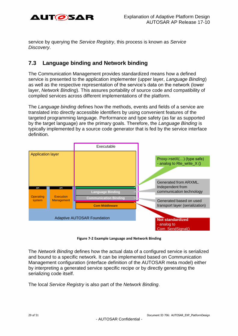
7.3 Language binding and Network binding
The Communication Management provides standardized means how a defined service is presented to the application implementer (upper layer, Language Binding) as well as the respective representation of the service’s data on the network (lower layer, Network Binding). This assures portability of source code and compatibility of compiled services across different implementations of the platform. The Language binding defines how the methods, events and fields of a service are translated into directly accessible identifiers by using convenient features of the targeted programming language. Performance and type safety (as far as supported by the target language) are the primary goals. Therefore, the Language Binding is typically implemented by a source code generator that is fed by the service interface definition.
Figure 7-2 Example Language and Network Binding
The Network Binding defines how the actual data of a configured service is serialized and bound to a specific network. It can be implemented based on Communication Management configuration (interface definition of the AUTOSAR meta model) either by interpreting a generated service specific recipe or by directly generating the serializing code itself. The local Service Registry is also part of the Network Binding.
Adaptive AUTOSAR Foundation
Application layer
Com Middleware
Communication Binding
Language Binding
Operating
system
API
Execution
Management
API
Executable
Generated based on used
transport layer (serialization)
Generated from ARXML.
Independent from
communication technology
Not standardized
- analog to
Com_SendSignal()
Proxy->setX(…) (type safe)
- analog to Rte_write_X ()

Explanation of Adaptive Platform Design AUTOSAR AP Release 17-10
30 of 51 Document ID 706: AUTOSAR_EXP_PlatformDesign
- AUTOSAR Confidential -
Please note: the interface between Language Binding and Network Binding is considered as a private interface inside Communication Management software. Therefore, a normative specification defining this interface is currently out of scope. Nevertheless, platform vendors are encouraged to define independently such an interface for their software to allow for easy implementation of other Language Bindings than C++ together with other Network Bindings inside their platform implementation.
7.4 Generated Proxies and Skeletons of C++ Language Binding
The upper layer interface of the C++ Language Binding provides an object-oriented mapping of the services defined in the interface description of the AUTOSAR meta model. A generator that is part of the development tooling for the Communication Management software generates C++ classes that contain type safe representations of the fields, events, and methods of each respective service. On the service implementation side, these generated classes are named Service Provider Skeletons. On the client side, they are called Service Requester Proxies. For Service Methods, a Service Requester Proxy provides mechanisms for synchronous (blocking the caller until the server returns a result) and asynchronous calling (called function returns immediately). A caller can start other activities in parallel and receives the result when the server’s return value is available via special features of the C++ standard template library (std::future). A platform implementation may be configured such that the generator creates mock-up classes for easy development of client functionality when the respective server is not yet available. The same mechanism can also be used for unit testing the client. Whereas proxy classes can be used directly by the client the Service Provider Skeletons for the C++ binding are just abstract base classes. A service implementation shall derive from the generated base class and implement the respective functionality. The interfaces of ara::com can also provide proxies and skeletons for safety related E2E protected communication. These interfaces are designed that compatibility to the applications is assured independent whether E2E protection is switched on or off.
7.5 Static and dynamic configuration
Configuration of communication paths can happen at design-, at startup- or at run-time and is therefore considered either static or dynamic:
Explanation of Adaptive Platform Design AUTOSAR AP Release 17-10
31 of 51 Document ID 706: AUTOSAR_EXP_PlatformDesign
- AUTOSAR Confidential -
Full static configuration: service discovery is not needed at all as the server knows all clients and clients know the server.
No discovery by application code: the clients know the server but the server does not know the clients. Event subscription is the only dynamic communication pattern in the application.
Full service discovery in the application: No communication paths are known at configuration time. An API for Service discovery allows the application code to choose the service instance at runtime.

Explanation of Adaptive Platform Design AUTOSAR AP Release 17-10
32 of 51 Document ID 706: AUTOSAR_EXP_PlatformDesign
- AUTOSAR Confidential -
8 RESTful Communication
8.1 Overview
Both communication stacks, ara::com and ara::rest can establish communication paths between Adaptive Applications. ara::rest is a framework to build RESTful APIs as well as specific services on top of such an API. It does not define a specific API out-of-the-box to construct directly RESTful services. This framework is modular, it enables developers to access different layers involved in RESTful message transactions directly. In contrast, the focus of ara::com is to provide a traditional function call interface and to hide all details of the transactions beyond this point. Another important difference is that ara::rest ensures interoperability with non-AUTOSAR peers. For example, an ara::rest service can communicate with a mobile HTTP/JSON client and vice versa.
8.2 Architecture
The Architecture of ara::rest is based on a modular design which supports developers at the level of API as well as service design. The following diagram illustrates its general design. It depicts how a service application is composed in ara::rest.
Figure 8-1 ara::rest stack architecture overview
The generic REST layer of ara::rest only provides three fundamental abstractions: A tree-structured message payload (Object Graph), a URI and a request method (like GET or POST known from HTTP). From these basic primitives domain-specific RESTful APIs can be composed which defines a concrete high-level protocol for interaction via object graphs, URI and methods. Its purpose is to define the rules for access into a domain-specific data model and to provide an abstract (C++) API to an application. Instead of using this Domain API, it is also possible for an Adaptive Application to use ara::rest directly when this further abstraction is not needed.

Explanation of Adaptive Platform Design AUTOSAR AP Release 17-10
33 of 51 Document ID 706: AUTOSAR_EXP_PlatformDesign
- AUTOSAR Confidential -
8.3 Components
ara::rest comprises of the following set of components.
Figure 8-2 ara::rest components
The Object Graph is a protocol-binding independent tree-like data structure which is the cornerstone of all ara::rest communication. Its purpose is to map to a protocol format such as JSON as well as to C structs. This maximizes compatibility with non-ARA communication peers and Classic AUTOSAR. Object graphs are transmitted in messages which abstract completely from a concrete underlying protocol binding. Still they enable a user to access protocol-specific details if required. Messages encapsulate the entire context of a request/reply communication cycle in the asynchronous programming model of ara::rest. The routing concept provides a means to map requests (including request method and URI) onto user-defined handler functions. Routing is the cornerstone to lift abstraction from generic REST into a specific kind of RESTful API. Uri is a generic RFC-compliant but highly efficient URI representation. ara::rest provides so-called (network) endpoints for server and client communication which both provide a comparable degrees of resource control. Both are designed to provide fast and efficient communication capabilities on single as well as multi-core systems. The entire framework design is strictly geared towards maximal resource control. All computations and allocations can be strictly controlled and customized to the precise needs of an application (deployment).

Explanation of Adaptive Platform Design AUTOSAR AP Release 17-10
34 of 51 Document ID 706: AUTOSAR_EXP_PlatformDesign
- AUTOSAR Confidential -
9 Diagnostics
9.1 Overview
The Diagnostic Management realizes the ISO 14229-5 (UDSonIP) which is mainly based on the ISO 14229-1 (UDS) and ISO 13400-2 (DoIP). The Diagnostic Management is an Adaptive Platform Service using ara::com. Therefore, it is language independent and may be able to serve Adaptive Applications with other language bindings e.g. Java in future. The configuration is based on the AUTOSAR Diagnostic Extract Template (DEXT) of the Classic Platform. DEXT starts to be settled in the market and is already used and supported by several OEMs and vendors. The supported Transport Layer is DoIP. Future Adaptive Platforms will support further Transport Layers e.g. CAN. Maybe also customized Transport Layers are also planned to be supported, because DoIP is typically not used as in-vehicle protocol. The scope is to abstract the diagnostic protocol from Adaptive Applications. The interfaces are harmonized with the Classic Platform (e.g. SetEventStatus) to allow an easy change for Classic Platform developers.
9.2 Diagnostic communication sub-cluster
The diagnostic communication sub-cluster is like the DCM of the Classic Platform – it realizes the diagnostic server. Currently the supported services are limited, but the support of further UDS services will be extended in future releases. Beside the pseudo parallel client handling of ISO 14229-1, the Diagnostic Manager (DM) is extended to support a full parallel handling of different diagnostic clients. This satisfies the demands of modern vehicle architectures including several diagnostic clients (tester) for data collection, access from the backend, SOTA (Software Over-the-Air) and finally the classic workshop and production use-cases. Diagnostic agnostic Adaptive Application (AA) In this case the DM uses an existing interface of an AA to fulfill a certain diagnostic request. The AAs interface, which DM uses to serve the diagnostic request, is an existing one, which cannot be changed and was NOT developed with diagnostic needs in mind. Adapting the existing interface in a way, which perfectly suits the diagnostic requirements/expectations defined by the tester is not an option, since AA shall not be changed.

Explanation of Adaptive Platform Design AUTOSAR AP Release 17-10
35 of 51 Document ID 706: AUTOSAR_EXP_PlatformDesign
- AUTOSAR Confidential -
The typical candidates for such use cases are UDS DataServices (RDBI), where some information provided by an AA anyway like vehicle speed shall be made accessible via UDS diagnostics. Diagnostic aware Adaptive Application (AA) In this case the DM dispatches an incoming diagnostic request (typically routine control or DID related service) to an AA, which provides an explicit diagnosis related interface (service interface specific to UDS service type. E.g. the service interface for a routine control consists of methods "start", "requetsResults" and "stop" and each method defines specific UDS error codes as application errors). Parameters parsed/serialized by AA itself from/to UINT8-Array in this case the entire UDS data-parameters starting with data-parameter#1 in the request and the entire UDS data-parameters starting with data-parameter#1 in the positive response are given as IN/OUT parameters of type UINT8-Array to the service method. Parameters given as typed in/out method parameters in this case the entire UDS data-parameters starting with data-parameter#1 in the request and the entire UDS data-parameters starting with data-parameter#1 in the positive response are given as distinct IN/OUT parameters of data type according to the type definition of the DiagnosticDataElement related to the data-parameter#N in DiagExt.
9.3 Event memory sub-cluster
The event memory sub-cluster is like DEM of the Classic Platform – it is responsible for DTC management. The supported functionality and interface are like the Classic Platform. The diagnostic monitor is represented as (Diagnostic-)Event which can be combined with a DTC. The DTC can be assigned to PrimaryMemory (accessible via 19 02/04/06) or to configurable UserMemories (accessible via 0x19 17/18/19). The DTC can store Snapshot- and ExtendedDataRecords. Counter- and Timebase Debouncing are supported. Furthermore, DM offers notifications about internal transitions: interested parties are informed about DTC status byte changes, the need of monitor re-initialization for DiagnosticEvents and if the Snapshot- or ExtendedDataRecord is changed. The operation cycle changes – important for the aging and readiness calculation – need to be forwarded to the DM. Same applies for the storage- and enable conditions – changes need to be forwarded to DM. By enable conditions the general update of DTCs can be controlled e.g. to

Explanation of Adaptive Platform Design AUTOSAR AP Release 17-10
36 of 51 Document ID 706: AUTOSAR_EXP_PlatformDesign
- AUTOSAR Confidential -
disable all network related monitors within under voltage conditions. By storage conditions the DTC cannot be stored in the DTC memory.

Explanation of Adaptive Platform Design AUTOSAR AP Release 17-10
37 of 51 Document ID 706: AUTOSAR_EXP_PlatformDesign
- AUTOSAR Confidential -
10 Persistency
10.1 Overview
Persistency offers mechanisms to Applications to store information in the non-volatile memory of an Adaptive Platform. The data is available over boot and ignition cycles. Persistency offers a library based approach to access the non-volatile memory. The Persistency library takes storage location identifiers as parameters from the application to address different storage locations. The available storage locations fall into two categories: - Key-Value Storage - File-Proxy Storage Every application may use a combination of multiple of these storage types. Persistent data is always private to one application. There is no mechanism available to share data between different applications using the Persistency library. This decision was taken to prevent a second communication path beneath the functionality provided by Communication Management. Persistency offers encryption for stored data to make sure that sensitive data will be encrypted before storing it on a physical device.
10.2 Key-Value Storage
Key-Value Storage provides a mechanism to store and retrieve multiple Key-Value pairs in one storage location. The supported value types are base types, PODs (C++ Plain Old Data structures) and arrays/containers derived from these types. The keys need to be unique strings per Key-Value database and are defined by an application using the methods provided by the Persistency library. Adding serialization/storage support for AUTOSAR data types which are defined in Application Design is planned.
10.3 File-Proxy Storage
It is obvious that not all data relevant for persistent storage is structured in such a way that Key-Value databases are a suitable storage mechanism. Therefore, the mechanism of File-Proxy Storage was introduced.

Explanation of Adaptive Platform Design AUTOSAR AP Release 17-10
38 of 51 Document ID 706: AUTOSAR_EXP_PlatformDesign
- AUTOSAR Confidential -
A File-Proxy Port allows an application to access a storage location and create one or multiple accessors in it. These accessors again are identified by unique keys in string format. To give a better impression of this mechanism, a comparison to a file system helps: a File-Proxy Port can be understood as a filesystem directory in which an application is allowed to create multiple files (accessors). Since File-Proxy Storage is close to classical file system access, the API was designed as subset of the well-known C++ std::iostream class with similar behavior.

Explanation of Adaptive Platform Design AUTOSAR AP Release 17-10
39 of 51 Document ID 706: AUTOSAR_EXP_PlatformDesign
- AUTOSAR Confidential -
11 Safety
11.1 Overview
Safety offers mechanisms to Adaptive Applications to protect the exchange of information inside the vehicle and with the external world. This will include mechanisms for inter- and intra-ECU communication. For this purpose, mechanisms provided will allow fault detection if any corruption has occurred. No mechanisms will be provided to guarantee the integrity of data. Safety also offers mechanisms to monitor the correct execution of platform functionalities and Adaptive Applications. This allows a defined handling of detected deviations. For this purpose, mechanisms provided will allow fault detection. No mechanisms will be provided to guarantee the integrity of applications. In addition, Safety offers guidelines such as coding guidelines, which facilitate the safe and secure usage of complex languages like C++. For the other Functional Clusters (e.g. Execution Management) guidance on possible safety implications will be provided and necessary enhancements will be integrated into the corresponding Functional Clusters. In general, Safety will provide concepts and documents that will support the development of an Adaptive Platform as Safety Element out of context. For example, there will be an overview of the provided safety features that will be supported by the Adaptive Platform. Safety expectations of system integrators will be addressed and so the development of safety cases will be supported. In a first step, the focus will be on safety mechanisms for fail-safe systems, but it will be extended to mechanisms for fail-operational systems in future.
11.2 Protection of information exchange (E2E-Protection)
Latest E2E profiles within AUTOSAR will be supported to allow safe communication between all combinations of AUTOSAR AP and CP instances, whether they are in the same or different ECUs. Where useful, mechanisms will be provided to allow safe communication using more capabilities of the service oriented approached within the Adaptive Platform. The provided functionality gives the possibility to verify that information sent from a publisher and received by a subscriber has not changed during the transmission. Acknowledgment of transmission and transmission security is not provided in the E2E context according to E2E mechanism in AUTOSAR CP. When E2E protection is used in communication between a publisher and a subscriber the E2E protection is invoked synchronously in the process of the

Explanation of Adaptive Platform Design AUTOSAR AP Release 17-10
40 of 51 Document ID 706: AUTOSAR_EXP_PlatformDesign
- AUTOSAR Confidential -
publisher. On the subscriber side the E2E checked is invoked at the reception of the data within the subscriber process. For this release E2E can be used for:
Periodic events in polling mode Not supported are:
Filtering and fail-safe values on top of periodic events in polling mode
Periodic events in callout mode
Aperiodic events in event mode
Aperiodic events in callout mode
Periodic methods
Aperiodic methods
11.3 Platform Health Management
In a first step, mechanisms will be provided to support fail-safe applications. The following aspects will be considered:
Alive supervision
Deadline supervision
Logical supervision
Error handling of supervision errors
Health Monitoring For this release only the platform independent specification (RS) will be provided within foundation.
11.4 C++ coding guidelines
The main application sector that AUTOSAR C++14 Coding Guidelines document applies to is automotive, but it can be used in other embedded applications that work in a safety-related and critical environments. The AUTOSAR C++14 Coding Guidelines rule set is applicable to high-end embedded micro-controllers that provide efficient and full C++14 language support, on 32 and 64 bit micro-controllers, using POSIX or similar operating systems. Existing standards are incomplete, covering old C++ versions or not applicable for critical/safety-related. In particular, MISRA C++:2008 does not cover C++11/14. Multiple new language features required analysis of how useful they can be in providing efficient implementations and how much risk is associated with the usage of each feature. Several other coding standards and resources are referenced in this document or used as a basis of the rules in this document, like JSF, HIC, CERT and C++ Core
Explanation of Adaptive Platform Design AUTOSAR AP Release 17-10
41 of 51 Document ID 706: AUTOSAR_EXP_PlatformDesign
- AUTOSAR Confidential -
Guideline. Most of the rules are automatically enforceable by static analysis that can be applicable without a manual code review. Style of code in a sense of naming conventions, layout or indentation are not be covered by the document. In the current release, the following are known limitations: 1. The rule set for parallel computing is not provided. 2. The rule set for C++ standard libraries is only initial (incomplete). 3. The rule set for security (as long as it is not common to critical software or safety- related software) is not provided. 4. The traceability to JSF, ISO CPP contains some non-analyzed rules. 5. The traceability to ISO 26262 is not provided.

Explanation of Adaptive Platform Design AUTOSAR AP Release 17-10
42 of 51 Document ID 706: AUTOSAR_EXP_PlatformDesign
- AUTOSAR Confidential -
12 Security
12.1 Overview
The security service offers the adaptive platform the means to harden the system e.g. by providing secure communication and an access management system.
12.2 Identity and Access Management
The AUTOSAR Adaptive Platform is recommended to employ an Identity and Access Management framework to enable authentication of individual AUTOSAR components (Adaptive AUTOSAR Applications, Services and Functional Clusters) as well as the concept for capabilities for managing roles and rights. With the IAM framework, access control decisions based on existing policies can be inquired by those applications. The inquiry will be handled through the functional clusters, as the applications do not have a direct interface to the IAM framework. Upon usage requests, Services will be able to utilize the specified framework to evaluate permissions and rights of the requester and accordingly enforce the corresponding policies.
The idea behind this framework is driven by the increasing need for security, as the AUTOSAR Adaptive Platform needs a robust and well-defined trust relationship with its applications. If an attacker compromises, an application it should not have any impact on the Adaptive Platform itself and the attackers’ capabilities should be restricted to the compromised applications capabilities. That is why applications should only be able to access system resources or trigger actions that they are supposed to. The IAM framework manages identities and access rights and can be seen as a comprehensible mechanism to restrict access of applications to the necessary minimum.
Scope of the IAM framework: The framework enforces access control between apps and functional clusters of the Adaptive Platform at runtime. Not in scope is the deployment/provisioning of AP applications, as the authentication of those applications is not covered by the IAM framework.
Contents of the AUTOSAR specification
The following table represents which parts of the IAM framework will be defined by AUTOSAR and which parts are up to the developer implementation-wise.
Description Affiliated to Part of
Access control policies (Manifest file information).
AUTOSAR specification
TPS_Manifest_Specification (of FT-MM)
Format and contents of AUTOSAR Requirement Specification (RS)

Explanation of Adaptive Platform Design AUTOSAR AP Release 17-10
43 of 51 Document ID 706: AUTOSAR_EXP_PlatformDesign
- AUTOSAR Confidential -
warnings/error messages that the applications receive on failed authorization.
specification
Contents of the logging information.
AUTOSAR Specification
Requirements (RS)
API for communication between Functional clusters and the IAM Manager.
Not specified by AUTOSAR
-
API for activity logging. Not specified by AUTOSAR
-
Scope and Focus of the IAM Framework
The main interface of the IAM Framework is the “request for an access control decision” which is directed from the PEP to the PDP of the implemented framework. Applications must not have control over the PEP or PDP as this would jeopardize the security concept behind IAM.
In addition to that, the IAM Framework can aid in the following aspects (not in scope for R10/17):
Key-management for establishment of secure connections or access to encrypted material
Authorization of applications at runtime (In case of applications being added after platform startup)
Distribution of Policies to other platform instances
Architecture of the IAM Framework
In this section, we describe an exemplary architecture that includes the IAM framework in the security functional cluster. However, the actual implementation can be shifted to or even distributed over other functional clusters without impact on its functionality. This is possible due to the flexibility of the framework as it does not specify where the decision or enforcement on the policy is made. However, it must ensure that it does not happen within the application.
To understand how the framework works, a few important notions must be defined in advance. The following list describes the major IAM components. As a reference see also ‘Terminology for Policy-Based Management’ in rfc3198 (https://tools.ietf.org/html/rfc3198).
Access Control Policy: This is an artefact which holds the information defining the basis for access control decisions. The necessary information is being stored in the application manifest files which are distributed during provisioning.

Explanation of Adaptive Platform Design AUTOSAR AP Release 17-10
44 of 51 Document ID 706: AUTOSAR_EXP_PlatformDesign
- AUTOSAR Confidential -
Access Control Decision: The access control decision is a Boolean value indicating if the requested operation is permitted or not. The access control decision is based on policies which are defined beforehand in the manifest file.
Policy Decision Point (PDP): This component represents the logic in which the access control decision is made. It determines if the application is allowed to perform the requested task.
Policy Enforcement Point (PEP): This component represents the logic in which the access control decision is enforced. It communicates directly with the PDP to receive the access control decision.
The high-level view on the architecture can be seen in Figure 12-1. The presented architecture should be considered as an example on how the framework can be applied. The concept behind this framework is flexible. For example, the policy manager can also be located outside of the security manager. It is up to the implementer to make adaptations if necessary.
Figure 12-1 High-level IAM Framework
The initial step in Figure 12-1 is the request. The application communicates with the functional cluster (FC) and requests a certain action for which the FC needs the authorization from the PDP inside the Security Manager. The FC calls its internal PEP, where a request to the PDP is triggered in order to check if the application is authorized to trigger the requested action. Upon receiving such a request, the PDP checks the associated database for manifest files which contain information on the desired request. It then evaluates weather the application is allowed to trigger the requested action and communicates the results to the PEP. This construct works because we assume that FCs inside the AUTOSAR stack are not compromised and sufficiently isolated from the potentially compromised application. Finally, the PEP enforces the decision it receives from the PDP and either permits or prohibits the desired request.

Explanation of Adaptive Platform Design AUTOSAR AP Release 17-10
45 of 51 Document ID 706: AUTOSAR_EXP_PlatformDesign
- AUTOSAR Confidential -
12.3 Crypto and Key Management (Crypto Stack)
AUTOSAR Adaptive Platform supports an API for common cryptographic operations and secure key management. The API supports the dynamic generation of keys and crypto jobs at runtime, as well as operating on data streams. To reduce storage requirements, keys may be stored internally in the crypto backend or externally and imported on demand. The API is designed to support encapsulation of security-sensitive operations and decisions in a separate component, such as a Hardware Security Module (HSM). Additional protection of keys and key usage can be provided by constraining keys to particular usages (e.g., decrypt-only), or limiting the availability of keys to individual applications as reported by IAM. Depending on application support, the API can also be used to protect session keys and intermediate secrets when processing cryptographic protocols such as TLS and SecOC.
Security Architecture
While AUTOSAR AP only defines the high-level Crypto Stack API exposed to applications, this API is defined with a security architecture in mind that was designed to meet above security and functional requirements. The general architecture is depicted in Figure 2. On the highest layer, AUTOSAR AP as well as native and hybrid applications link against the AUTSAR AP Crypto Stack API. The API implementation may refer to a central unit (Crypto Service Manager) to implement platform-level tasks such as access control and certificate storage consistently across applications. The implementation may also use the Crypto Service Manager to coordinate the offloading of functionality to a Crypto Driver, such as a Hardware Security Module (HSM). Indeed, offloading functionality of the Crypto Stack API this way is expected to be a typical implementation strategy: The Crypto Driver may implement the complete set of key management and crypto functions in order to accelerate crypto operations and shield managed keys from malicious applications.

Explanation of Adaptive Platform Design AUTOSAR AP Release 17-10
46 of 51 Document ID 706: AUTOSAR_EXP_PlatformDesign
- AUTOSAR Confidential -
Figure 2 Crypto Stack - Reference Architecture
In order to realize this layered security architecture, the Crypto Stack API not only performs bulk crypto operations but also provides native support for:
(1) Operating with encrypted keys or key handles (2) Managing keys securely despite possible application compromise (3) Constraining application access to and allowed operations on keys
Key Management Architecture
To support the secure remote management of keys despite potential application compromise, the Crypto Stack integrates a key management architecture where keys and associated data are managed in end-to-end protected form. Keys can be introduced into the system either in a trusted fashion, based on an existing provisioning key, or in an untrusted fashion via local key generation. Assuming an appropriately secured crypto backend / driver, applications are unable to modify keys except via well-defined, authorized requests such as key update or revocation.

Explanation of Adaptive Platform Design AUTOSAR AP Release 17-10
47 of 51 Document ID 706: AUTOSAR_EXP_PlatformDesign
- AUTOSAR Confidential -
Figure 3 CKI Key Management Interactions
Remarks on API Extension
Significant new usages and interactions that require the introduction of new or modified permission/policy validation logic should be tied to corresponding new key usage policy flags. For example, alternative provisioning keys with different ownership/permission checks can be introduced by adding a corresponding new key usage policy and enforcing the new logic in all key management operations involving those new keys.

Explanation of Adaptive Platform Design AUTOSAR AP Release 17-10
48 of 51 Document ID 706: AUTOSAR_EXP_PlatformDesign
- AUTOSAR Confidential -
13 Update and Configuration Management
13.1 Overview
One of the declared goals of Adaptive AUTOSAR is the ability to flexibly update the software and its configuration through over-the-air updates. To support changes in the software on an Adaptive Platform the Update and Configuration Manager(UCM) provides an Adaptive Platform service that handles software update requests. UCM is responsible for updating, installing, removing and keeping a record of the software on an Adaptive Platform. Its role is similar to known package management systems like dpkg or YUM in Linux, with additional functionality to ensure a safe and secure way to update or modify software on the Adaptive Platform.
13.2 Software Package processing
Beside application and configuration data each Software Package contains a manifest providing metadata like package name, version and other meta information needed for processing the package. The data content of a Software Package can contain, for example, one or several Adaptive Applications, kernel or firmware updates, or updated configuration and calibration data. UCM processes software packages based on the provided metadata and the Adaptive Platform software information.
13.3 Software information reporting
UCM provides service interfaces that expose functionality to retrieve Adaptive Platform software information, such as names and versions of installed software.
13.4 Software update consistency
UCM ensures that only validated packages with all the described dependencies fulfilled are installed. This way no unwanted or unfitting software will be installed. UCM provides an interface to read the installation result. In case of a failure during the update process, UCM recovers the platform to a known functional state. An example of a recoverable failure would be an interrupted update process due to a power loss.
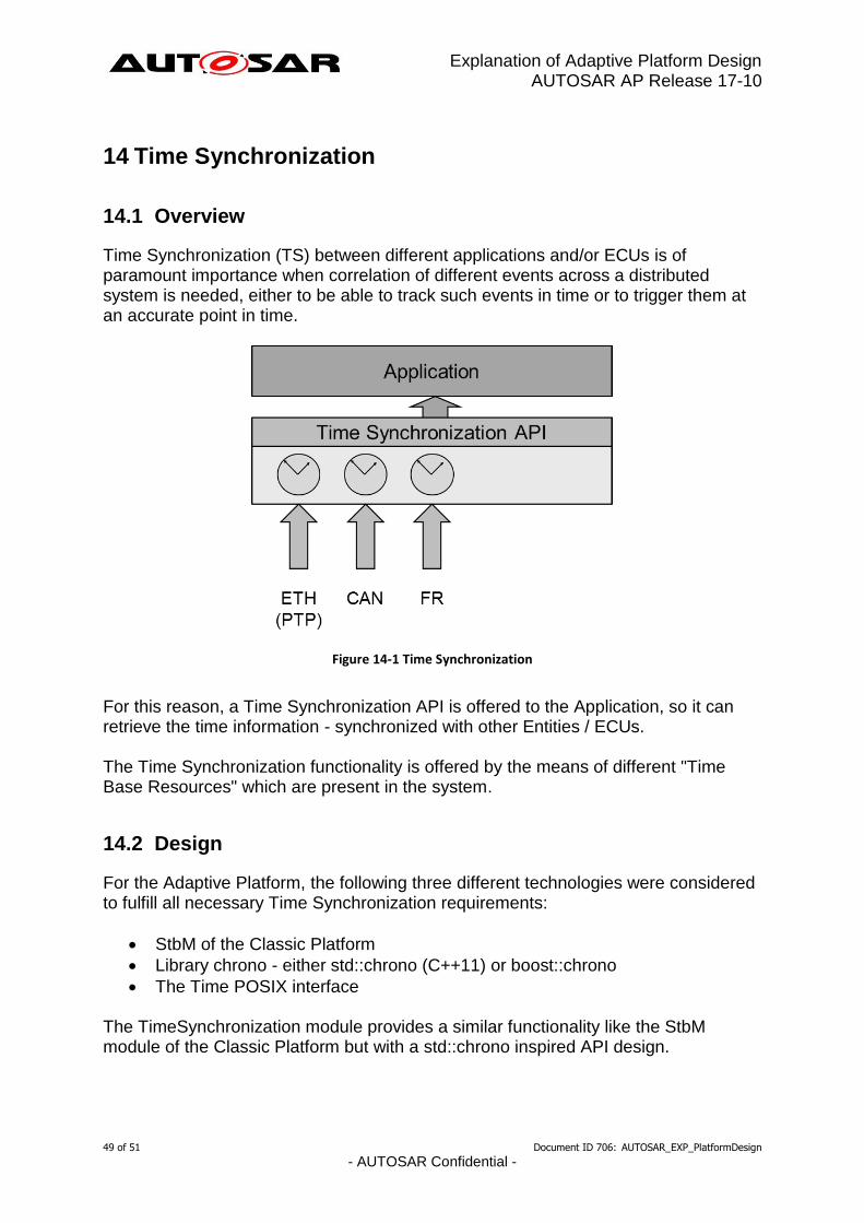
Explanation of Adaptive Platform Design AUTOSAR AP Release 17-10
49 of 51 Document ID 706: AUTOSAR_EXP_PlatformDesign
- AUTOSAR Confidential -
14 Time Synchronization
14.1 Overview
Time Synchronization (TS) between different applications and/or ECUs is of paramount importance when correlation of different events across a distributed system is needed, either to be able to track such events in time or to trigger them at an accurate point in time.
Figure 14-1 Time Synchronization
For this reason, a Time Synchronization API is offered to the Application, so it can retrieve the time information - synchronized with other Entities / ECUs. The Time Synchronization functionality is offered by the means of different "Time Base Resources" which are present in the system.
14.2 Design
For the Adaptive Platform, the following three different technologies were considered to fulfill all necessary Time Synchronization requirements:
StbM of the Classic Platform
Library chrono - either std::chrono (C++11) or boost::chrono
The Time POSIX interface The TimeSynchronization module provides a similar functionality like the StbM module of the Classic Platform but with a std::chrono inspired API design.

Explanation of Adaptive Platform Design AUTOSAR AP Release 17-10
50 of 51 Document ID 706: AUTOSAR_EXP_PlatformDesign
- AUTOSAR Confidential -
The following functional aspects are considered by the Time Synchronization module:
Startup Behavior
Constructor Behavior (Initialization)
Normal Operation
Error Handling The following functional aspects will be considered in future releases:
Shutdown Behavior
Error Classification
Version Check
14.3 Architecture
The application will have access to a different specialized class implementation for each Time Base Resource (TBR).
The TBRs are offered as a Resource in a similar way as Services are offered in the ara::com design and therefore it is adopting the following architectural design patterns of ara::com:
Proxy: Similar to the ara::com Service Proxy Skeleton pattern, TS provides a Resource Proxy pattern, omitting the Skeleton part.
Find: Similar to the ara::com Service Proxy Find pattern, TS provides a Resource Proxy Find pattern to provide access to TBRs.
Proxy Methods: Similar to the ara::com Proxy Methods pattern, TS uses a Methods pattern also adhering to the asynchronous Future pattern.
This architectural design puts the Time Synchronization design apparently in a frontal conflict when talking about avoiding latencies, since the latter are inherently added by the asynchronous behavior of the design pattern of the ara::com API.

Explanation of Adaptive Platform Design AUTOSAR AP Release 17-10
51 of 51 Document ID 706: AUTOSAR_EXP_PlatformDesign
- AUTOSAR Confidential -
15 References
[1] Glossary, AUTOSAR_TR_Glossary.pdf.
[2] Main Requirement, AUTOSAR_RS_Main.pdf.
[3] Methodology for Adaptive Platform, AUTOSAR_TR_AdaptiveMethodology.pdf.
[4] Design guidelines for using parallel processing technologies on Adaptive Platform, AUTOSAR_EXP_ParallelProcessingGuidelines.pdf.