explanatory note - ventilation...
TRANSCRIPT

Explanatory note
On internal Specific Fan Power, SFPint and draft transitional methods
Preliminary DRAFT prepared for the first stakeholder meeting of the Technical Assistance Study of the Ventilation Units Product Group
15 June 2015
(www.ventilationunits.eu)
Page 2
Explanatory note on SFPint and transitional methods (preliminary
DRAFT for discussion at stakeholder meeting 15 June)
1. Introduction ............................................................................................................................ 3
2. SFPint – Definition, reference configuration, questions from stakeholders ..... 4
3. Consideration regarding measurements of SFPint .................................................... 9
1: Mass-produced standardised compact NRVUs. ........................................................... 9
2: Tailor-made NRVUs ................................................................................................................ 9
Roadmap: ...................................................................................................................................... 10
4. Review of submitted proposal for measurement and calculation of SFPint ... 11
5. Summarized alternative to determinate SFPint (DTI) ........................................... 14
6. Test of alternative determination of SFPint ................................................................ 17
7. A simple method for measuring pressure inside the unit ................................... 18
8. Ventilation components data.......................................................................................... 23
Annex 1 Draft calculation and measurement of SFPint ..................................................... 24
Page 3
1. Introduction
This explanatory note is focussing on the internal specific fan power of ventilation components
'SFPint' which is a part of COMMISSION REGULATION (EU) No 1253/2014 of 7 July 2014
implementing Directive 2009/125/EC of the European Parliament and of the Council with regard to
ecodesign requirements for ventilation units
The note has been prepared based on a number of proposals for determining SFPint as well as
questions on clarification of SFPint that have been submitted to the Commission.
The note shall be considered a background document for the transitional methods of SFPint.
The resulting draft transitional methods are included in the Annex 1 of this note.
See Annex 1 for the proposed draft transitional method of SFPint
The explanatory note is slightly different from a normal procedure, as it starts with clarification of
the definition of SFPint by answering some of the questions submitted and by explaining (justifying)
the answers (Chapter 2). Next section (Chapter 3) is presenting some general considerations about
measuring SFPint of ventilation units. Chapter 4 is reviewing proposals submitted on measurements
and calculation of SFPint. Measuring the internal pressure drop inside a ventilation unit can be very
difficult. Chapter 5 summarizes an alternative method to determine SFPint without measuring inside
the unit. In Chapter 6, the alternative method is tested and compared with other methods. In case,
the internal pressure drop can be measured, Chapter 7 is proposing a simple method for measuring
inside the ventilation unit. Finally, Chapter 8 is summarizing some of the challenges of calculation
of SFPint for a whole unit according to measurements of single components.
In the regulation, in the standards and within Industry different wordings are used for the same
entities. Consequently, the following should be taken into account in the document:
Inlet-side is interpreted as in the supply air side (air stream) (SUP)
Extract-side is interpreted as the exhaust air side (air stream) (EHA)
Modular NRVU constructed/designed each time for a specific task is considered as a
'Tailor-made NRVU'
Standardised compact NVRUs not constructed/designed for at specific task but with a wide
operation area are to considered as a 'mass-produced standardized compact NRVU'
For the measurement and calculation of SFPint all characteristics/values are converted from the
ambient temperature and pressure measured at the time of the test, to standard air conditions
20°C and 101325 Pa approximately equal to an air density of 1,2 kg/m³.
Page 4
2. SFPint – Definition, reference configuration, questions from stakeholders
A large number of SMEs have found the regulation difficult to understand, and want a simple and
straightforward description of SFPint to make sure that they follow the regulation correct. Such
description is sought by answering some of the questions submitted and by explaining (justifying)
the answers in the following.
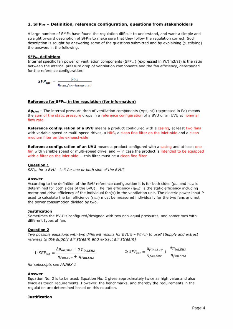
SFPint definition:
Internal specific fan power of ventilation components (SFPint) (expressed in W/(m3/s)) is the ratio
between the internal pressure drop of ventilation components and the fan efficiency, determined
for the reference configuration:
Reference for SFPint in the regulation (for information)
Δps,int – The internal pressure drop of ventilation components (Δps,int) (expressed in Pa) means
the sum of the static pressure drops in a reference configuration of a BVU or an UVU at nominal
flow rate.
Reference configuration of a BVU means a product configured with a casing, at least two fans
with variable speed or multi-speed drives, a HRS, a clean fine filter on the inlet-side and a clean
medium filter on the exhaust-side
Reference configuration of an UVU means a product configured with a casing and at least one
fan with variable speed or multi-speed drive, and — in case the product is intended to be equipped
with a filter on the inlet-side — this filter must be a clean fine filter
Question 1
SFPint for a BVU - is it for one or both side of the BVU?
Answer
According to the definition of the BVU reference configuration it is for both sides (pint and nstat is
determined for both sides of the BVU). The 'fan efficiency (ηfan)' is the static efficiency including
motor and drive efficiency of the individual fan(s) in the ventilation unit. The electric power input P
used to calculate the fan efficiency (ηfan) must be measured individually for the two fans and not
the power consumption divided by two.
Justification
Sometimes the BVU is configured/designed with two non-equal pressures, and sometimes with
different types of fan.
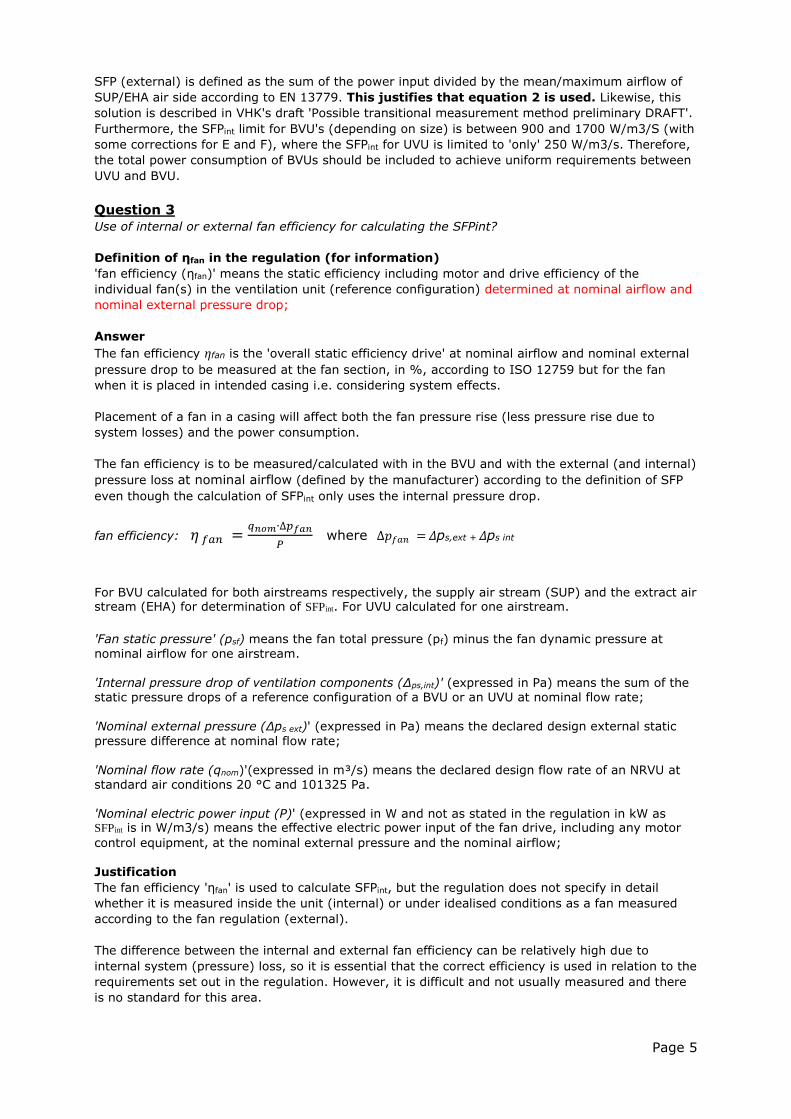
Question 2
Two possible equations with two different results for BVU's – Which to use? (Supply and extract
referees to the supply air stream and extract air stream)
for subscripts see ANNEX 1
Answer
Equation No. 2 is to be used. Equation No. 2 gives approximately twice as high value and also
twice as tough requirements. However, the benchmarks, and thereby the requirements in the
regulation are determined based on this equation.
Justification
1: 𝑆𝐹𝑃𝑖𝑛𝑡 =∆𝑝𝑖𝑛𝑡,𝑆𝑈𝑃 + ∆ 𝑝𝑖𝑛𝑡,𝐸𝐻𝐴
𝜂𝑓𝑎𝑛,𝑆𝑈𝑃 + 𝜂𝑓𝑎𝑛,𝐸𝐻𝐴 2: 𝑆𝐹𝑃𝑖𝑛𝑡 =
∆𝑝𝑖𝑛𝑡,𝑆𝑈𝑃𝜂𝑓𝑎𝑛,𝑆𝑈𝑃
+ ∆𝑝𝑖𝑛𝑡,𝐸𝐻𝐴
𝜂𝑓𝑎𝑛,𝐸𝐻𝐴
Page 5
SFP (external) is defined as the sum of the power input divided by the mean/maximum airflow of
SUP/EHA air side according to EN 13779. This justifies that equation 2 is used. Likewise, this
solution is described in VHK's draft 'Possible transitional measurement method preliminary DRAFT'.
Furthermore, the SFPint limit for BVU's (depending on size) is between 900 and 1700 W/m3/S (with
some corrections for E and F), where the SFPint for UVU is limited to 'only' 250 W/m3/s. Therefore,
the total power consumption of BVUs should be included to achieve uniform requirements between
UVU and BVU.
Question 3
Use of internal or external fan efficiency for calculating the SFPint?
Definition of ηfan in the regulation (for information)
'fan efficiency (ηfan)' means the static efficiency including motor and drive efficiency of the
individual fan(s) in the ventilation unit (reference configuration) determined at nominal airflow and
nominal external pressure drop;
Answer
The fan efficiency ηfan is the 'overall static efficiency drive' at nominal airflow and nominal external
pressure drop to be measured at the fan section, in %, according to ISO 12759 but for the fan
when it is placed in intended casing i.e. considering system effects.
Placement of a fan in a casing will affect both the fan pressure rise (less pressure rise due to
system losses) and the power consumption.
The fan efficiency is to be measured/calculated with in the BVU and with the external (and internal)
pressure loss at nominal airflow (defined by the manufacturer) according to the definition of SFP
even though the calculation of SFPint only uses the internal pressure drop.
fan efficiency: 𝜂 𝑓𝑎𝑛 =𝑞𝑛𝑜𝑚∙∆𝑝𝑓𝑎𝑛
𝑃 where ∆𝑝𝑓𝑎𝑛 = Δps,ext + Δps int
For BVU calculated for both airstreams respectively, the supply air stream (SUP) and the extract air stream (EHA) for determination of SFPint. For UVU calculated for one airstream.
'Fan static pressure' (psf) means the fan total pressure (pf) minus the fan dynamic pressure at
nominal airflow for one airstream. 'Internal pressure drop of ventilation components (Δps,int)' (expressed in Pa) means the sum of the static pressure drops of a reference configuration of a BVU or an UVU at nominal flow rate; 'Nominal external pressure (Δps ext)' (expressed in Pa) means the declared design external static
pressure difference at nominal flow rate; 'Nominal flow rate (qnom)'(expressed in m³/s) means the declared design flow rate of an NRVU at standard air conditions 20 °C and 101325 Pa. 'Nominal electric power input (P)' (expressed in W and not as stated in the regulation in kW as SFPint is in W/m3/s) means the effective electric power input of the fan drive, including any motor
control equipment, at the nominal external pressure and the nominal airflow; Justification The fan efficiency 'ηfan' is used to calculate SFPint, but the regulation does not specify in detail
whether it is measured inside the unit (internal) or under idealised conditions as a fan measured
according to the fan regulation (external).
The difference between the internal and external fan efficiency can be relatively high due to
internal system (pressure) loss, so it is essential that the correct efficiency is used in relation to the
requirements set out in the regulation. However, it is difficult and not usually measured and there
is no standard for this area.
Page 6
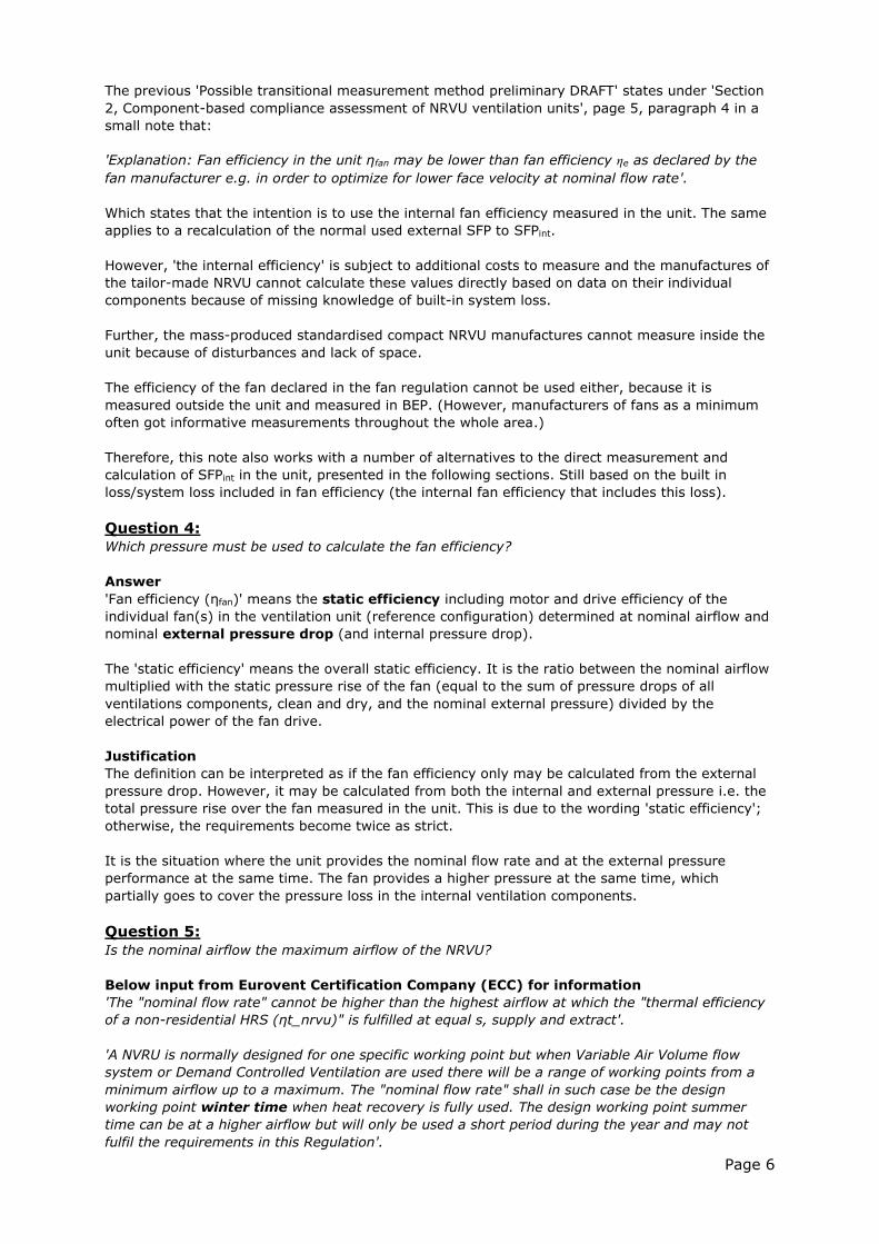
The previous 'Possible transitional measurement method preliminary DRAFT' states under 'Section
2, Component-based compliance assessment of NRVU ventilation units', page 5, paragraph 4 in a
small note that:
'Explanation: Fan efficiency in the unit ηfan may be lower than fan efficiency ηe as declared by the
fan manufacturer e.g. in order to optimize for lower face velocity at nominal flow rate'.
Which states that the intention is to use the internal fan efficiency measured in the unit. The same
applies to a recalculation of the normal used external SFP to SFPint.
However, 'the internal efficiency' is subject to additional costs to measure and the manufactures of
the tailor-made NRVU cannot calculate these values directly based on data on their individual
components because of missing knowledge of built-in system loss.
Further, the mass-produced standardised compact NRVU manufactures cannot measure inside the
unit because of disturbances and lack of space.
The efficiency of the fan declared in the fan regulation cannot be used either, because it is
measured outside the unit and measured in BEP. (However, manufacturers of fans as a minimum
often got informative measurements throughout the whole area.)
Therefore, this note also works with a number of alternatives to the direct measurement and
calculation of SFPint in the unit, presented in the following sections. Still based on the built in
loss/system loss included in fan efficiency (the internal fan efficiency that includes this loss).
Question 4:
Which pressure must be used to calculate the fan efficiency?
Answer
'Fan efficiency (ηfan)' means the static efficiency including motor and drive efficiency of the
individual fan(s) in the ventilation unit (reference configuration) determined at nominal airflow and
nominal external pressure drop (and internal pressure drop).
The 'static efficiency' means the overall static efficiency. It is the ratio between the nominal airflow
multiplied with the static pressure rise of the fan (equal to the sum of pressure drops of all
ventilations components, clean and dry, and the nominal external pressure) divided by the
electrical power of the fan drive.
Justification
The definition can be interpreted as if the fan efficiency only may be calculated from the external
pressure drop. However, it may be calculated from both the internal and external pressure i.e. the
total pressure rise over the fan measured in the unit. This is due to the wording 'static efficiency';
otherwise, the requirements become twice as strict.
It is the situation where the unit provides the nominal flow rate and at the external pressure
performance at the same time. The fan provides a higher pressure at the same time, which
partially goes to cover the pressure loss in the internal ventilation components.
Question 5:
Is the nominal airflow the maximum airflow of the NRVU?
Below input from Eurovent Certification Company (ECC) for information
'The "nominal flow rate" cannot be higher than the highest airflow at which the "thermal efficiency
of a non-residential HRS (ηt_nrvu)" is fulfilled at equal s, supply and extract'.
'A NVRU is normally designed for one specific working point but when Variable Air Volume flow
system or Demand Controlled Ventilation are used there will be a range of working points from a
minimum airflow up to a maximum. The "nominal flow rate" shall in such case be the design
working point winter time when heat recovery is fully used. The design working point summer
time can be at a higher airflow but will only be used a short period during the year and may not
fulfil the requirements in this Regulation'.
Page 7
Answer
The nominal airflow and pressure must be seen as the maximum airflow of the NRVU in the sale of
which the NRVU can fulfil the requirements according to the definitions in the regulation:
Definition of nominal flow rate in the regulation:
'Nominal flow rate (qnom)' (expressed in m3/s) means the declared design flow rate of an NRVU at
standard air conditions 20 °C and 101 325 Pa, whereby the unit is installed complete (for example,
including filters) and according to the manufacturer instructions.
The design point is usually the maximum conditions the VU must meet according to demands from
the contractor.
Justification
Mostly the same point is used for summertime and wintertime, and this interpretation will provide
a huge loophole and can therefore not be used.
In winter, ventilation demands are mostly due to the atmospheric indoor climate, and in the
summer due to the thermal indoor climate. The airflow demand for atmospheric indoor climate
(winter) is often lower than the thermal (summer) because of the cooling demand in summer.
However, in winter there is also often the demand for heat, which increases the airflow. Likewise,
in summer, there is often a demand for cooling recovery, when the air outside has a higher
temperature than the air inside the building, which increases the airflow over the HRS and does not
make it lower than in the winter.
Question (claim) 6
What is the nominal airflow when using a mixing section?
Below input from Eurovent Certification Company (ECC) for information
'When a mixing section is installed, HRS and filter are selected for outdoor air demand only and in
some cases they are not able to handle the full design flow rate of the unit – calculate the internal
pressure losses of the ventilation components (HRS+filter) for the design airflow. If they are
designed only for the outdoor air and not for the total airflow, calculate only the outdoor air part.
Fan characteristics, system losses, fan efficiency etc. shall be calculated with the total airflow
through the fan'.
Answer
Measurements and declaration must be performed as a 'normal' unit with a heat recovery system,
not recirculating.
Question 7
Can an area be used instead of only one point?
Answer
Final formulation to be still confirmed. Preliminary input:
NVRU consists of two main groups, i.e. tailor-made NVRUs and mass-produced standardised
compact NVRUs. They deviate in the matter of working point. A tailor-made NVRU is designed for
specific working points but a compact NVRU is used for a wide range of working points.
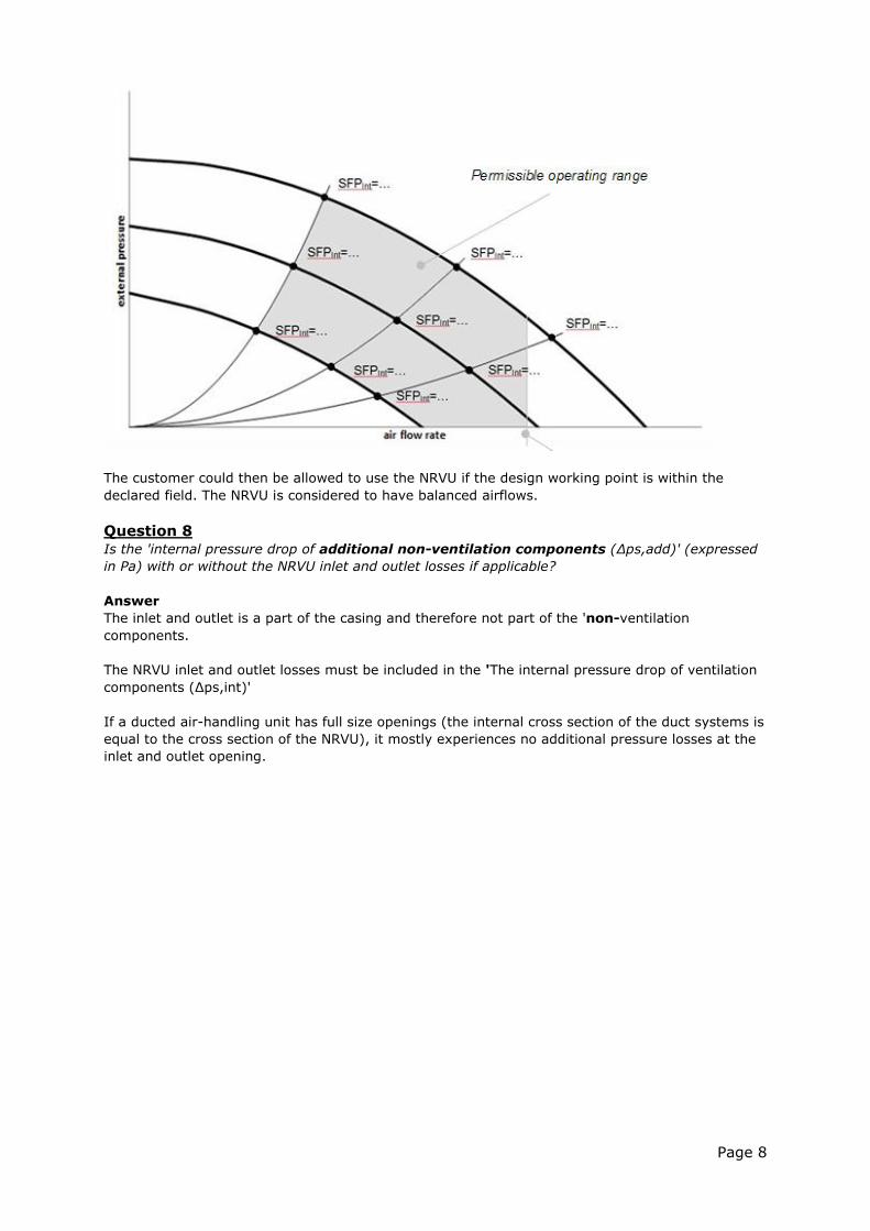
If the working point is not specified by the customer, which can be the case for a small mass-
produced compact NVRU, one could declare a field (graph) of nominal airflows with associated
'nominal external pressure (Δps, ext)', see below (The NRVU is considered to have balanced
airflows).
Page 8
The customer could then be allowed to use the NRVU if the design working point is within the
declared field. The NRVU is considered to have balanced airflows.
Question 8
Is the 'internal pressure drop of additional non-ventilation components (Δps,add)' (expressed
in Pa) with or without the NRVU inlet and outlet losses if applicable?
Answer
The inlet and outlet is a part of the casing and therefore not part of the 'non-ventilation
components.
The NRVU inlet and outlet losses must be included in the 'The internal pressure drop of ventilation
components (Δps,int)'
If a ducted air-handling unit has full size openings (the internal cross section of the duct systems is
equal to the cross section of the NRVU), it mostly experiences no additional pressure losses at the
inlet and outlet opening.
Page 9
3. Consideration regarding measurements of SFPint
The regulation is faced with two issues that must be taken into consideration:
1: Mass-produced standardised compact NRVUs.
Documentation is easy because they are mass-produced and the manufacturer often measures on
one unit that is applicable to all. However, on these units the internal pressure drop is difficult to
measure because they are compact and with large disturbances. In this instance, it is important
that there is an alternative or a secure way to measure the internal pressure
2: Tailor-made NRVUs
In these units, it is easier to measure the internal pressure because the face velocity is often lower.
However, they are customised and manufactured in thousands of different configurations. Here the
manufactures mostly rely on measurements of single components and assemble them in an overall
performance based on customer requirements in their product selection programme. Units will not
be measured separately and only occasionally randomly (if they are members of a certification
scheme). In this instance, it is important that the method take into consideration that
manufacturers within some uncertainty is able to calculate the internal pressure drop and efficiency
by measuring on the individual components.
Approach
The internal pressure used to calculate SFPint cannot be measured with the current standards. This
also applies to the fan efficiency (ηfan). It is important that SFPint and associated values can be
measured and verified, but it is also equally important that:
1. The values can be measured in the laboratory.
2. The values can be calculated in the manufacturers' product selection programmes from
measurements/knowledge of the individual incoming components.
3. SFPint has to be calculated with a minimum of extra measurements.
4. Should be useful for both compact and tailor-made units.
What is essential is to find SFPint that is equal to the energy consumption (loss) in W/m3/h caused
by the 'not ideal' fan installation in the unit and the pressure loss-making components (filter, heat
exchanger and the casing).
The big question is how to measure/calculate the fan installation system loss and the additional pressure loss caused by the casing (mainly in and outlet, and secondly not idealized built in components). DTI has previously measured on units in many different ways to find a solution on how to measure correctly inside a unit:
with a large number of measuring points inside the unit after each component; measurement with fans switch off and air pulled/pushed through the system from the
outside, where it turned out that the lack of rotation had a strong influence and improved the performance unintended in relation to the true values;
with pitot tube measurements in a grid with a large number of measuring points; and with anemometer measurements (to analyse the face velocity grid and thereby the
difference in dynamic and static pressure) in a grid with a large number of measuring points.
All measurements provided unequal results, and it could not be determined whether one was more correct than the other one. This resulted for the specific verification scheme at that time in an agreement that pressure was to be measured on pressure taps mounted by the manufacturer. This is not an ideal method, but a way for laboratories and manufacturers to measure identical at low
cost. Therefore, DTI's focus is to find:
1. an alternative to the measurements inside unit (using external values); and
2. a simple method for measuring pressure inside the unit.
The focus is a method that can rank the product in accordance with regulations and can be
measured and calculated within an appropriate uncertainty.
Page 10
Roadmap:
The determination of the internal pressure drop and fan efficiency is the key element for the
calculation of SFP int.
1. Methods for determination of SFPint a. Indirect determination by comparison of fan data and unit data
i. A simple method for measuring pressure inside the unit correctly b. Measurement - A simple method for measuring pressure inside the unit correctly
i. Direct measurement over all components ii. Indirect measurement by removing components
c. Reliable components data i. Calculation from components data
2. Declaration which method is used a. Which method for which units b. Tolerances
3. Experience with methods 1a and 1.b.
1.c is not part of the transitional methods but will be taken into consideration. Manufacturers can
rely on their individual component data calculated to overall performance of the unit, but test
activity will be conducted according to 1.a and 1.b
A number of manufacturers have supplied proposals on these topics, which DTI has evaluated and
tested in the laboratory and summarised in one proposal (see Chapter 5 and 6). Manufacturers are
invited to share their preliminary testing results based on the presented methodology, in order to
further assess its easiness of use.
In the next chapter follows a brief description of the various proposals. For further clarification,
reference is made to the proposal in question.
Page 11
4. Review of submitted proposal for measurement and calculation of SFPint
It is our intention to publish the different proposals in the ‘Documents’ section of the
webpage www.ventilationunits.eu before the first stakeholder meeting. We will use the
numbering (I to VII) to refer to the different proposals.
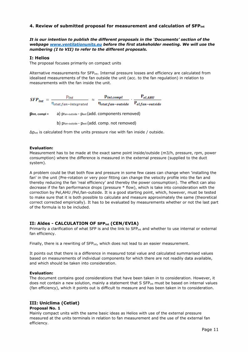
I: Helios
The proposal focuses primarily on compact units
Alternative measurements for SFPint. Internal pressure losses and efficiency are calculated from
idealised measurements of the fan outside the unit (acc. to the fan regulation) in relation to
measurements with the fan inside the unit.
pint, compl = a) pfan-outside - pext (add. components removed)
b) pfan-outside - pext (add. comp. not removed)
Δpint is calculated from the units pressure rise with fan inside / outside.
Evaluation:
Measurement has to be made at the exact same point inside/outside (m3/h, pressure, rpm, power
consumption) where the difference is measured in the external pressure (supplied to the duct
system).
A problem could be that both flow and pressure in some few cases can change when 'installing the
fan' in the unit (Pre-rotation or very poor fitting can change the velocity profile into the fan and
thereby reducing the fan 'real efficiency' and thereby the power consumption). The effect can also
decrease if the fan performance drops (pressure * flow), which is take into consideration with the
correction by Pel,AHU /Pel,fan-outside. It is a good starting point, which, however, must be tested
to make sure that it is both possible to calculate and measure approximately the same (theoretical
correct corrected empirically). It has to be evaluated by measurements whether or not the last part
of the formula is to be included.
II: Aldes - CALCULATION OF SFPint (CEN/EVIA)
Primarily a clarification of what SFP is and the link to SFPint and whether to use internal or external
fan efficiency.
Finally, there is a rewriting of SFPint, which does not lead to an easier measurement.
It points out that there is a difference in measured total value and calculated summarised values
based on measurements of individual components for which there are not readily data available,
and which should be taken into consideration.
Evaluation:
The document contains good considerations that have been taken in to consideration. However, it
does not contain a new solution, mainly a statement that S SFPint must be based on internal values
(fan efficiency), which it points out is difficult to measure and has been taken in to consideration.
III: Uniclima (Cetiat)
Proposal No. 1
Mainly compact units with the same basic ideas as Helios with use of the external pressure
measured at the units terminals in relation to fan measurement and the use of the external fan
efficiency.
Page 12
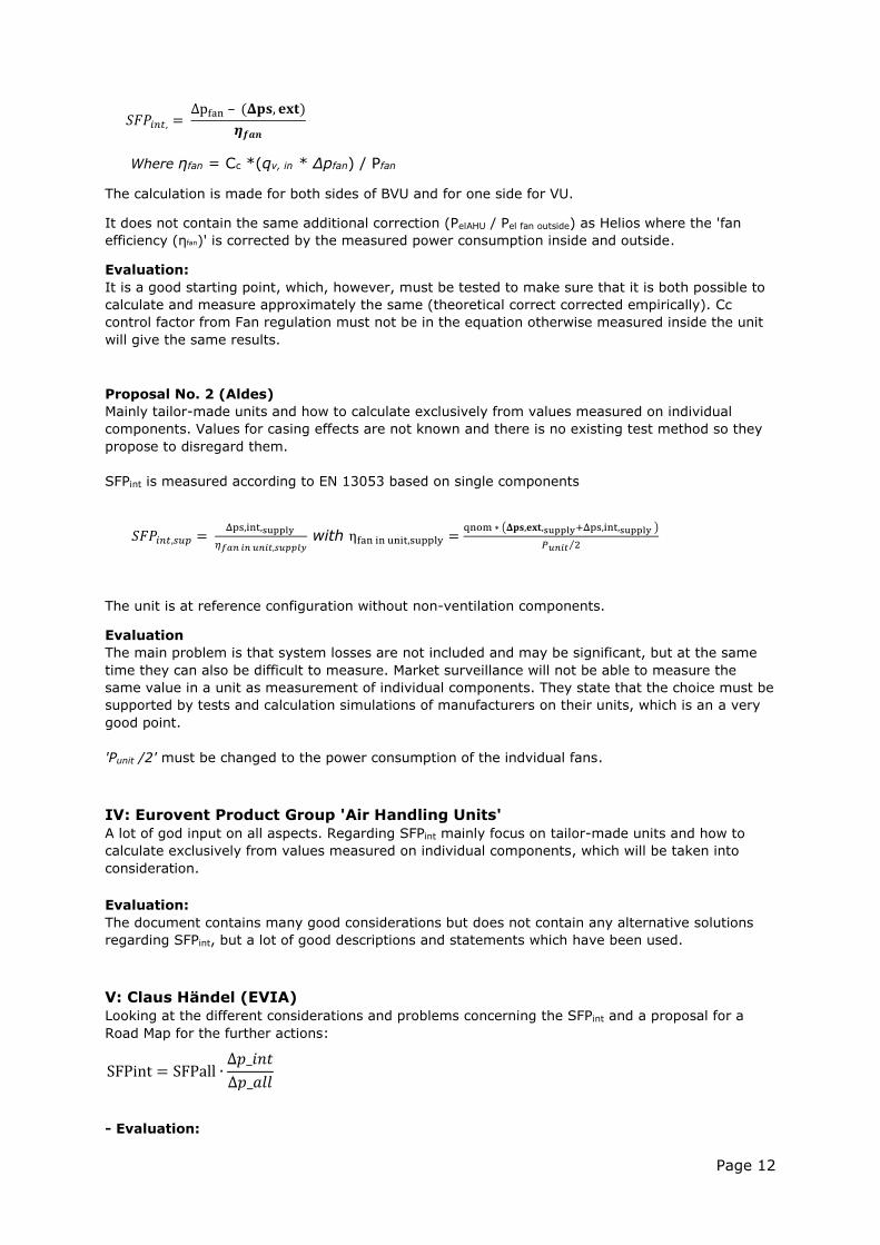
𝑆𝐹𝑃𝑖𝑛𝑡, = Δpfan – (𝚫𝐩𝐬, 𝐞𝐱𝐭)
𝜼𝒇𝒂𝒏
Where ηfan = Cc *(qv, in * Δpfan) / Pfan
The calculation is made for both sides of BVU and for one side for VU.
It does not contain the same additional correction (PelAHU / Pel fan outside) as Helios where the 'fan
efficiency (ηfan)' is corrected by the measured power consumption inside and outside.
Evaluation:
It is a good starting point, which, however, must be tested to make sure that it is both possible to
calculate and measure approximately the same (theoretical correct corrected empirically). Cc
control factor from Fan regulation must not be in the equation otherwise measured inside the unit
will give the same results.
Proposal No. 2 (Aldes)
Mainly tailor-made units and how to calculate exclusively from values measured on individual
components. Values for casing effects are not known and there is no existing test method so they
propose to disregard them.
SFPint is measured according to EN 13053 based on single components
𝑆𝐹𝑃𝑖𝑛𝑡,𝑠𝑢𝑝 = Δps,int,supply
𝜂𝑓𝑎𝑛 𝑖𝑛 𝑢𝑛𝑖𝑡,𝑠𝑢𝑝𝑝𝑙𝑦 with ηfan in unit,supply =
qnom ∗ (𝚫𝐩𝐬,𝐞𝐱𝐭,supply+Δps,int,supply )
𝑃𝑢𝑛𝑖𝑡 2⁄
The unit is at reference configuration without non-ventilation components.
Evaluation
The main problem is that system losses are not included and may be significant, but at the same
time they can also be difficult to measure. Market surveillance will not be able to measure the
same value in a unit as measurement of individual components. They state that the choice must be
supported by tests and calculation simulations of manufacturers on their units, which is an a very
good point.
'Punit /2' must be changed to the power consumption of the indvidual fans.
IV: Eurovent Product Group 'Air Handling Units'
A lot of god input on all aspects. Regarding SFPint mainly focus on tailor-made units and how to
calculate exclusively from values measured on individual components, which will be taken into
consideration.
Evaluation:
The document contains many good considerations but does not contain any alternative solutions
regarding SFPint, but a lot of good descriptions and statements which have been used.
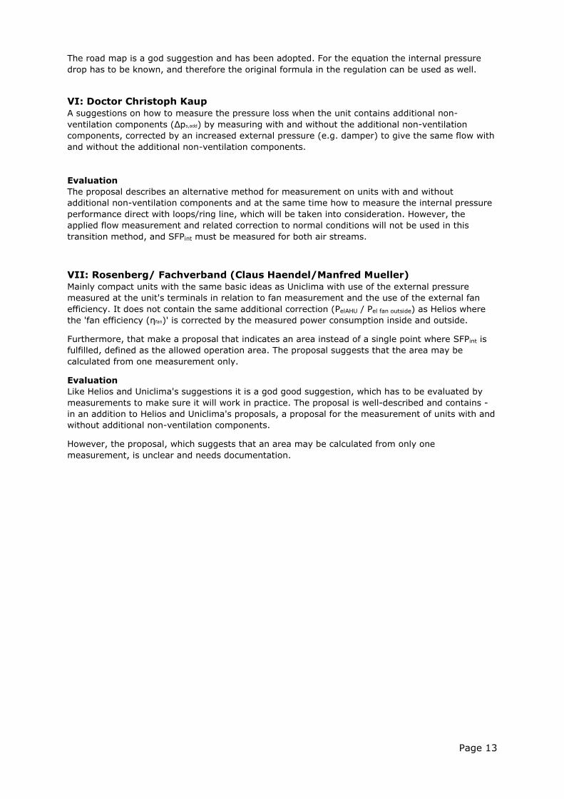
V: Claus Händel (EVIA)
Looking at the different considerations and problems concerning the SFPint and a proposal for a
Road Map for the further actions:
- Evaluation:
SFPint = SFPall ∙∆𝑝_𝑖𝑛𝑡
∆𝑝_𝑎𝑙𝑙
Page 13
The road map is a god suggestion and has been adopted. For the equation the internal pressure
drop has to be known, and therefore the original formula in the regulation can be used as well.
VI: Doctor Christoph Kaup
A suggestions on how to measure the pressure loss when the unit contains additional non-
ventilation components (Δps,add) by measuring with and without the additional non-ventilation
components, corrected by an increased external pressure (e.g. damper) to give the same flow with
and without the additional non-ventilation components.
Evaluation
The proposal describes an alternative method for measurement on units with and without
additional non-ventilation components and at the same time how to measure the internal pressure
performance direct with loops/ring line, which will be taken into consideration. However, the
applied flow measurement and related correction to normal conditions will not be used in this
transition method, and SFPint must be measured for both air streams.
VII: Rosenberg/ Fachverband (Claus Haendel/Manfred Mueller)
Mainly compact units with the same basic ideas as Uniclima with use of the external pressure
measured at the unit's terminals in relation to fan measurement and the use of the external fan
efficiency. It does not contain the same additional correction (PelAHU / Pel fan outside) as Helios where
the 'fan efficiency (ηfan)' is corrected by the measured power consumption inside and outside.
Furthermore, that make a proposal that indicates an area instead of a single point where SFPint is
fulfilled, defined as the allowed operation area. The proposal suggests that the area may be
calculated from one measurement only.
Evaluation
Like Helios and Uniclima's suggestions it is a god good suggestion, which has to be evaluated by
measurements to make sure it will work in practice. The proposal is well-described and contains -
in an addition to Helios and Uniclima's proposals, a proposal for the measurement of units with and
without additional non-ventilation components.
However, the proposal, which suggests that an area may be calculated from only one
measurement, is unclear and needs documentation.
Page 14
5. Summarized alternative to determinate SFPint (DTI)
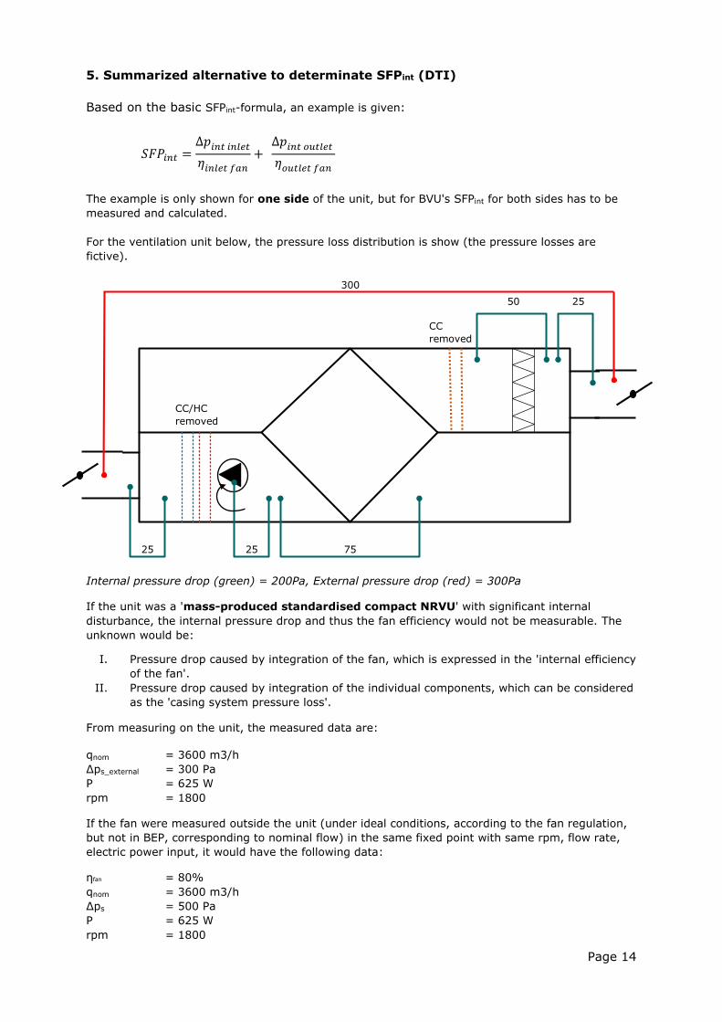
Based on the basic SFPint-formula, an example is given:
The example is only shown for one side of the unit, but for BVU's SFPint for both sides has to be
measured and calculated.
For the ventilation unit below, the pressure loss distribution is show (the pressure losses are
fictive).
Internal pressure drop (green) = 200Pa, External pressure drop (red) = 300Pa
If the unit was a 'mass-produced standardised compact NRVU' with significant internal
disturbance, the internal pressure drop and thus the fan efficiency would not be measurable. The
unknown would be:
I. Pressure drop caused by integration of the fan, which is expressed in the 'internal efficiency
of the fan'.
II. Pressure drop caused by integration of the individual components, which can be considered
as the 'casing system pressure loss'.
From measuring on the unit, the measured data are:
qnom = 3600 m3/h
Δps_external = 300 Pa
P = 625 W
rpm = 1800
If the fan were measured outside the unit (under ideal conditions, according to the fan regulation,
but not in BEP, corresponding to nominal flow) in the same fixed point with same rpm, flow rate,
electric power input, it would have the following data:
ηfan = 80%
qnom = 3600 m3/h
Δps = 500 Pa
P = 625 W
rpm = 1800
25 25 75
2550
VFKF
300
CC/HC
removed
300
CC
removed
𝑆𝐹𝑃𝑖𝑛𝑡 =∆𝑝𝑖𝑛𝑡 𝑖𝑛𝑙𝑒𝑡
𝜂𝑖𝑛𝑙𝑒𝑡 𝑓𝑎𝑛
+ ∆𝑝𝑖𝑛𝑡 𝑜𝑢𝑡𝑙𝑒𝑡
𝜂𝑜𝑢𝑡𝑙𝑒𝑡 𝑓𝑎𝑛
Page 15
The fan stays at the same working point (inside/outside the unit) on the fan curve, but we can only
observe an external pressure drop. Right before the fan, the fan sees the same working situation
as the test outside, but we only observe the external pressure, or if we measure inside only the
pressure without the system loss around the fan.
The difference in the external pressure drop (300Pa) and the ideal measuring of the fan (500Pa),
which is 200Pa in this situation, is an expression of both the total internal pressure loss AND the
internal efficiency of the fan.
This way it may be reasonable to use the external efficiency of the fan instead of the internal
efficiency to calculate SFPint as the loss is covered by the measured pressure difference between
the two measurements.
A problem is that the electric power input can change when installing the fan in the unit (pre-
rotation or poor installation can change the velocity profile into the fan and thereby reduce the
fan's 'real efficiency' and thereby the power consumption in 'the same point'). The effect can also
decrease if the fan performance drops (pressure * flow).
There may be system losses not related to an asymmetric inlet to the fan, but due to other flow
conditions in the casing between the pressure measuring point and fan. These will be reflected in
the difference in pressure between the two measurements (inside/outside) and will not lead to
different power consumption.
This problem can be solved by using a correction between the power consumption in the two
measurements. This leads to the final formula for calculation of SFPint:
Rewritten to standard terms it becomes:
Values is inserted with numerical values for p. All values is calculated for SUP or EHA for
UVU’s depending on whether it is a SUP or EHA fan unit and calculated values for SUP and
EHA for BVU’s.
Where
pFan means the static pressure difference of the fan measured outside the
unit according to the fan regulation, not in best efficiency point (BEP),
but corresponding to the nominal flow and rpm regarding the unit
regulation (according to the measurements conducted on the unit).
ps,ext means the static nominal external pressure drop as described under
Annex A1.2.3 measured at the terminals at the unit.
Fan means the static efficiency including motor and drive efficiency of the
individual fan(s) in the ventilation unit (reference configuration)
determined at nominal air flow and nominal external and internal pressure
drop (and corresponding revolutions of the fan installed inside the unit)
𝑆𝐹𝑃𝑖𝑛𝑡 =∆𝑝𝑓𝑎𝑛 𝑒𝑥𝑡− ∆𝑝𝑢𝑛𝑖𝑡 𝑒𝑥𝑡
𝜂𝑒𝑥𝑡 𝑓𝑎𝑛
𝑆𝐹𝑃𝑖𝑛𝑡 =∆𝑝𝑓𝑎𝑛 𝑜𝑢𝑡𝑠𝑖𝑑𝑒 − ∆𝑝𝑠_𝑒𝑥𝑡
𝑓𝑎𝑛 𝑜𝑢𝑡𝑠𝑖𝑑𝑒∙
𝑃𝑢𝑛𝑖𝑡𝑃𝐹𝑎𝑛 𝑜𝑢𝑡𝑠𝑖𝑑𝑒
SFP𝑖𝑛𝑡 𝑈𝑉𝑈 =∆𝑝𝐹𝑎𝑛 − ∆𝑝𝑠,𝑒𝑥𝑡
𝐹𝑎𝑛∙
𝑃𝐹𝐴𝑁𝑃𝐹𝑎𝑛,𝑒𝑥𝑡
SFP𝑖𝑛𝑡 𝐵𝑉𝑈 =∆𝑝𝐹𝑎𝑛,𝑆𝑈𝑃 − ∆𝑝𝑠,𝑒𝑥𝑡,𝑆𝑈𝑃
𝐹𝑎𝑛,𝑆𝑈𝑃∙
𝑃𝐹𝑎𝑛,𝑆𝑈𝑃𝑃𝐹𝑎𝑛,𝑒𝑥𝑡,𝑆𝑈𝑃
+ ∆𝑝𝐹𝑎𝑛,𝐸𝐻𝐴 − ∆𝑝𝑠,𝑒𝑥𝑡,𝐸𝐻𝐴
𝐹𝑎𝑛,𝐸𝐻𝐴∙
𝑃𝐹𝑎𝑛,𝐸𝐻𝐴𝑃𝐹𝑎𝑛,𝑒𝑥𝑡,𝐸𝐻𝐴
Page 16
measured outside the unit according to the fan regulation.
The static efficiency is the ratio between the nominal air flow
multiplied with the static pressure rise of the fan (equal to the sum of
pressure drops for all ventilations components, clean and dry, and the
nominal external pressure) divided by the electrical power to the fan
drive.
PFan is the ‘nominal electric power input (P)’ (expressed in W) and means the
effective electric power input of the fan drives, including any motor control
equipment, at the nominal external pressure and the nominal airflow,
measured on the unit.
PFan,ext is ‘nominal electric power input (P)’ (expressed in W) and means the
effective electric power input of the fan drives, including any motor control
equipment, at the nominal airflow and revolutions of the fan installed
inside the unit and corresponding pFan measured outside the unit
according to the fan regulation
If the unit is equipped with control equipment (inverter, etc.) ηfan shall be reduced and
𝑃𝑒𝑙,𝑓𝑎𝑛,𝑒𝑥𝑡 must be increased with the loss of the control unit. Alternatively, the data from
the fan manufacturer must have been measured with the same equipment.
For the measurement and calculation of SFPint all characteristics/values are converted
from the ambient temperature and pressure measured at the time of the test, to
standard air conditions 20°C and 101325 Pa approximately equal to an air density of 1,2
kg/m³.
For further information regarding symbols and subscripts, see Annex 1.
Page 17
6. Test of alternative determination of SFPint
Based on the previous proposal, the different calculation methods have been tested and measured
using two types of ventilation units in DTI's accredited laboratories: A compact and a tailor-made
unit.
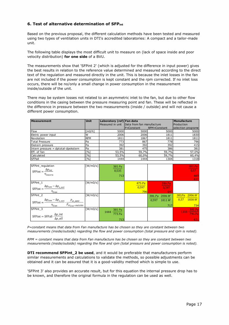
The following table displays the most difficult unit to measure on (lack of space inside and poor
velocity distribution) for one side of a BVU.
The measurements show that 'SFPint 2' (which is adjusted for the difference in input power) gives
the best results in relation to the reference value determined and measured according to the direct
text of the regulation and measured directly in the unit. This is because the inlet losses in the fan
are not included if the power consumption is kept constant and the rpm corrected. If no inlet loss
occurs, there will be no/only a small change in power consumption in the measurement
inside/outside of the unit.
There may be system losses not related to an asymmetric inlet to the fan, but due to other flow
conditions in the casing between the pressure measuring point and fan. These will be reflected in
the difference in pressure between the two measurements (inside / outside) and will not cause a
different power consumption.
P=constant means that data from Fan manufacture has be chosen so they are constant between two
measurements (inside/outside) regarding the flow and power consumption (total pressure and rpm is noted).
RPM = constant means that data from Fan manufacture has be chosen so they are constant between two
measurements (inside/outside) regarding the flow and rpm (total pressure and power consumption is noted).
DTI recommend SFPint_2 be used, and it would be preferable that manufacturers perform
similar measurements and calculations to validate the methods, so possible adjustments can be
obtained and it can be assured that it is a good-validity method which is simple to use.
'SFPint 3' also provides an accurate result, but for this equation the internal pressure drop has to
be known, and therefore the original formula in the regulation can be used as well.
Measurement Unit Laboratory (ref) Fan data Manufacture
Measured in unit Data from fan manufacture Production
P=Constant RPM=Constant selection programe
Flow [m3/h] 5000 5000 5000 5000
Eletric power input W 2006 2006 1811 1830
Revolution RPM 1811 1867 1811 1811
Total Pressure Pa 773 867 778 796
Ekstern pressure Pa 392 392 392 415
Intern pressure = dptotal-dpekstern Pa 381 475 386 381
Eff. of fan [%] 53,5% 59,7% 59,7% 57,0%
Calculated [%] 53,5% 60,0% 59,7% 60,4%
SFPall [%] 1444 1444 1304 1318
SFPint_regulation [W/m3/s]
713 669
631
SFPint_1 [W/m3/s]
796 647
SFPint_2 [W/m3/s]
717 734
SFPint_3 [W/m3/s]
713 631
𝑃𝑎
,
𝑃𝑎
,
1 𝑃𝑎
,
1 𝑃𝑎
,
𝑃𝑎
, ∙2
1 11
1𝑃𝑎
, ∙2
1
1 1 ∙ 1 𝑃𝑎
𝑃𝑎SFPint = SFPall ∙
∆𝑝_𝑖𝑛𝑡
∆𝑝_𝑎𝑙𝑙
SFPint =∆𝑝𝑓𝑎𝑛−∆𝑝𝑠_𝑒𝑥𝑡
𝑓𝑎𝑛
SFPint =∆𝑝𝑓𝑎𝑛−∆𝑝𝑠_𝑒𝑥𝑡
𝑓𝑎𝑛∙
𝑃𝑒𝑙_𝐴𝐻𝑈𝑃𝑒𝑙𝑓𝑎𝑛−𝑜𝑢𝑡𝑠𝑖𝑑𝑒
SFPint =∆𝑝𝑖𝑛𝑡𝑖𝑛𝑡𝑒 𝑛
1 ∙ 1 𝑃𝑎
𝑃𝑎
Page 18
7. A simple method for measuring pressure inside the unit
In the current standards there are several good description of how to measure in a long, straight
duct with non-rotating air and disturbances. There are also standards describing traversing
measurements and alternative measurement plans in situ. However, there is no existing standard
that describes where, how, and in how many points to measure the pressure inside a unit.
It is important that traversing measurement with pitot tube for example is not used, as it will
increase the test period and cost significantly and make data logging impossible. Furthermore, it is
important that the measuring equipment does not cause a disturbance in the airflow or result in a
pressure drop.
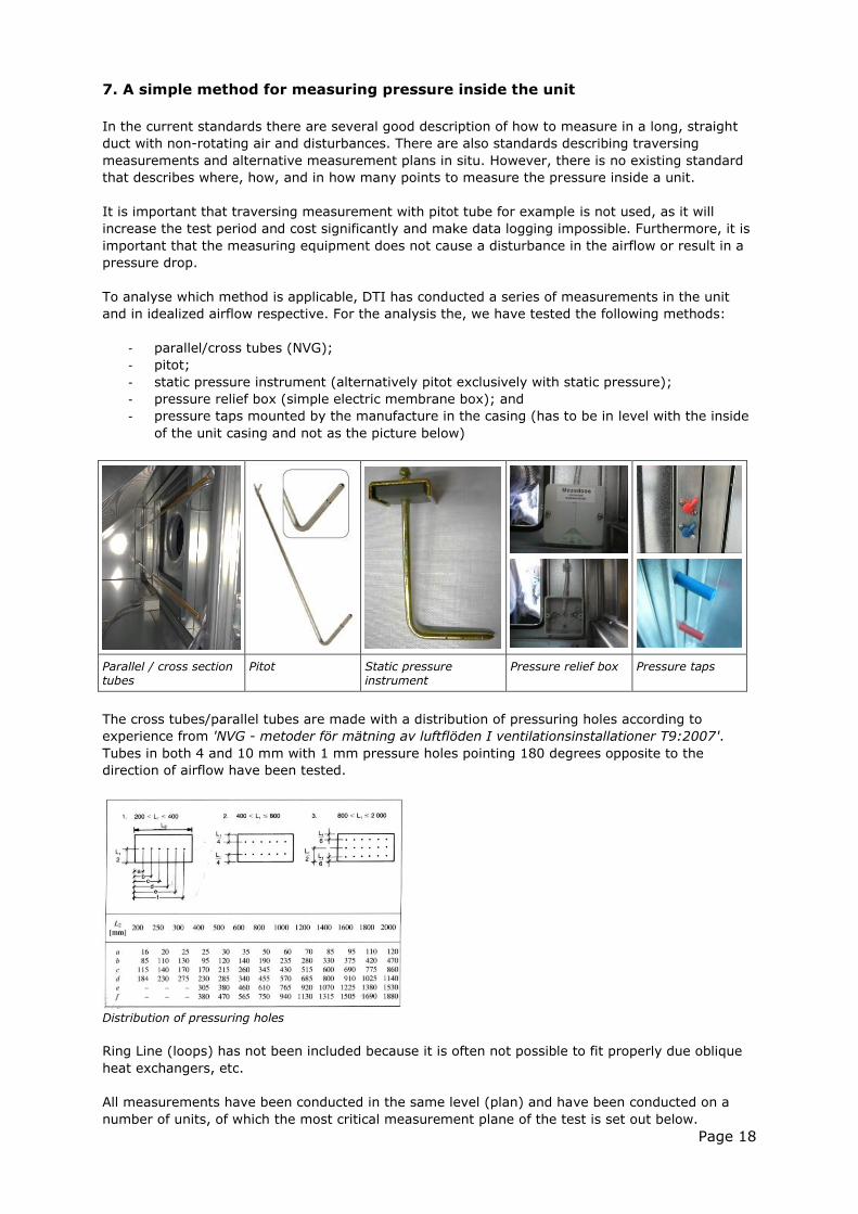
To analyse which method is applicable, DTI has conducted a series of measurements in the unit
and in idealized airflow respective. For the analysis the, we have tested the following methods:
- parallel/cross tubes (NVG);
- pitot;
- static pressure instrument (alternatively pitot exclusively with static pressure);
- pressure relief box (simple electric membrane box); and
- pressure taps mounted by the manufacture in the casing (has to be in level with the inside
of the unit casing and not as the picture below)
Parallel / cross section tubes
Pitot
Static pressure instrument
Pressure relief box Pressure taps
The cross tubes/parallel tubes are made with a distribution of pressuring holes according to
experience from 'NVG - metoder för mätning av luftflöden I ventilationsinstallationer T9:2007'.
Tubes in both 4 and 10 mm with 1 mm pressure holes pointing 180 degrees opposite to the
direction of airflow have been tested.
Distribution of pressuring holes
Ring Line (loops) has not been included because it is often not possible to fit properly due oblique
heat exchangers, etc.
All measurements have been conducted in the same level (plan) and have been conducted on a
number of units, of which the most critical measurement plane of the test is set out below.
Page 19
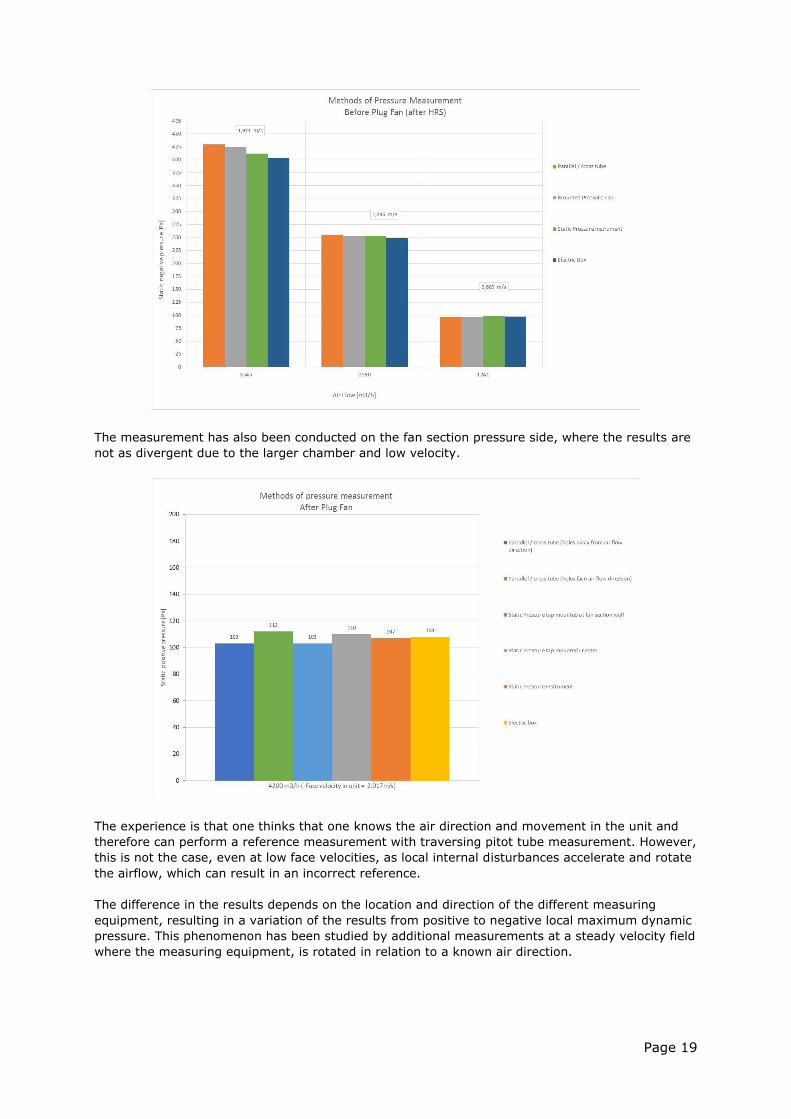
The measurement has also been conducted on the fan section pressure side, where the results are
not as divergent due to the larger chamber and low velocity.
The experience is that one thinks that one knows the air direction and movement in the unit and
therefore can perform a reference measurement with traversing pitot tube measurement. However,
this is not the case, even at low face velocities, as local internal disturbances accelerate and rotate
the airflow, which can result in an incorrect reference.
The difference in the results depends on the location and direction of the different measuring
equipment, resulting in a variation of the results from positive to negative local maximum dynamic
pressure. This phenomenon has been studied by additional measurements at a steady velocity field
where the measuring equipment, is rotated in relation to a known air direction.
Page 20
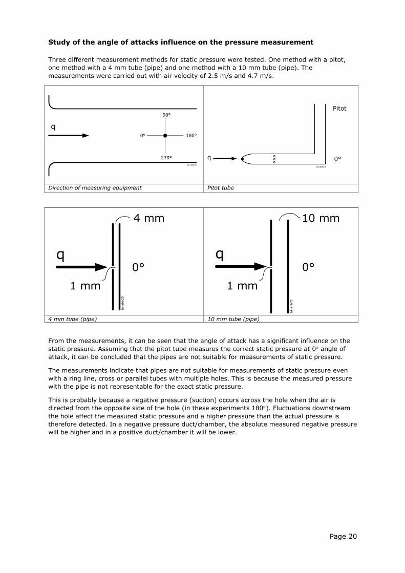
Study of the angle of attacks influence on the pressure measurement
Three different measurement methods for static pressure were tested. One method with a pitot,
one method with a 4 mm tube (pipe) and one method with a 10 mm tube (pipe). The
measurements were carried out with air velocity of 2.5 m/s and 4.7 m/s.
Direction of measuring equipment Pitot tube
4 mm tube (pipe) 10 mm tube (pipe)
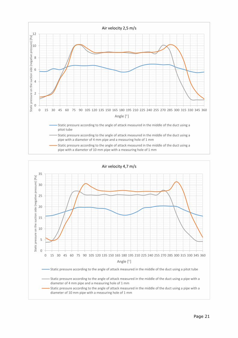
From the measurements, it can be seen that the angle of attack has a significant influence on the
static pressure. Assuming that the pitot tube measures the correct static pressure at 0 angle of
attack, it can be concluded that the pipes are not suitable for measurements of static pressure.
The measurements indicate that pipes are not suitable for measurements of static pressure even
with a ring line, cross or parallel tubes with multiple holes. This is because the measured pressure
with the pipe is not representable for the exact static pressure.
This is probably because a negative pressure (suction) occurs across the hole when the air is
directed from the opposite side of the hole (in these experiments 180). Fluctuations downstream
the hole affect the measured static pressure and a higher pressure than the actual pressure is
therefore detected. In a negative pressure duct/chamber, the absolute measured negative pressure
will be higher and in a positive duct/chamber it will be lower.
q0°
4 mm
1 mm
10 mm
1 mm
0° q
Pitot
q 0° hk-ehh19
90°
180° 0°
270°
q
hk-ehh18
Page 21
0
2
4
6
8
10
12
0 15 30 45 60 75 90 105 120 135 150 165 180 195 210 225 240 255 270 285 300 315 330 345 360Stat
ic p
ress
ure
on
th
e su
ctio
n s
ide
(neg
ativ
e p
ress
ure
) [P
a]
Angle []
Air velocity 2,5 m/s
Static pressure according to the angle of attack measured in the middle of the duct using apitot tube
Static pressure according to the angle of attack measured in the middle of the duct using apipe with a diameter of 4 mm pipe and a measuring hole of 1 mm
Static pressure according to the angle of attack measured in the middle of the duct using apipe with a diameter of 10 mm pipe with a measuring hole of 1 mm
0
5
10
15
20
25
30
35
0 15 30 45 60 75 90 105 120 135 150 165 180 195 210 225 240 255 270 285 300 315 330 345 360
Stat
ic p
ress
ure
on
th
e su
ctio
n s
ide
(neg
ativ
e p
ress
ure
) [P
a]
Angle []
Air velocity 4,7 m/s
Static pressure according to the angle of attack measured in the middle of the duct using a pitot tube
Static pressure according to the angle of attack measured in the middle of the duct using a pipe with adiameter of 4 mm pipe and a measuring hole of 1 mm
Static pressure according to the angle of attack measured in the middle of the duct using a pipe with adiameter of 10 mm pipe with a measuring hole of 1 mm
Page 22
Recommendation:
The best result was obtained with a very simple solution by using one or more pressure relief box
(electrical membrane box) with holes on the back. When measuring inside the unit, we recommend using a pressure relief box (electrical membrane
box) under the following conditions:
placed on a fluidically quiet location;
at a distance from stagnation regions;
located on a plane surface;
prepare with only one hole in the bottom of the box (centre);
the back of the box of must be equipped with spacers (distance buds) that ensure a
distance between the box and the casing of approximately 1-2 mm; and
the fan must not blow directly on the box, and if the fan blows along a surface, for
example, at the bottom of the unit, the box cannot be placed at this surface.
Pressure measurements inside the unit should not be conducted at face velocities above 3m/s
according to the experiences of ECC and DTI. However, there must be great awareness of local
reduction of the cross sectional area that can increase the local velocity significantly and lead to
incorrect measurement, although the face velocity based on the free area in the unit is respected.
Page 23
8. Ventilation components data
It is not a part of the standard/transitional methods to deal with the calculation of a whole unit
according to measurements of single components, but this can be a challenging task.
Here the manufacturer does not know:
I. Pressure drop caused by integration of the fan, which is expressed in the 'internal efficiency
of the fan'.
Manufacturer may know by experience (when they are a part of a scheme, have a product
selection programme, etc.):
II. Pressure drop caused by integration of the individual components, which can be considered
as the 'casing system pressure loss'
The value 'I' can be calculated approximately by the loss of dynamic pressure regarding to radial
fans. This is, however, not the same for plug/box free blowing fans and axial fans. Nevertheless, a
correction can be made in some way. However, in many cases the influence of asymmetric inlet to
the fan cannot be calculated.
It is the DTI's laboratory experience that there are often up to 20% difference between the
manufacturer's specified pressure drop over components (single component data from production
selection/designing program) and the values measured at the laboratory inside the unit
(reference), which is why it is very important that manufacturers take this seriously.
Page 24
Annex 1 Draft calculation and measurement of SFPint
To be adopted in draft transitional methods document
Based on the background analysis as described in the “Explanatory note on internal Specific Fan Power, SFPint and draft transitional methods” this Annex proposes that the following methods are used to determine SFPint.
A1.1 Terminology related SFPint values For consensus between standards and regulations, symbols and subscripts from prEN 16798-3 has
been adopted for the cases where no such are described in Regulations 1253/2014 and 1254/2014.
Where there is inconsistency between symbols used in the standard and the regulations, the
regulations symbols are used. Reference is to prEN 16798-3 as the revision of this standard is
advanced and that RVU and NRVU relevant standards under revision might therefore adopt the
prEN 16798-3 symbols and subscripts.
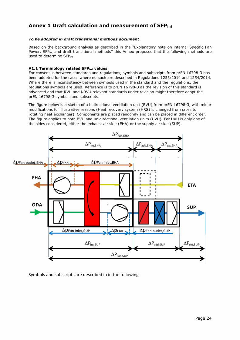
The figure below is a sketch of a bidirectional ventilation unit (BVU) from prEN 16798-3, with minor
modifications for illustrative reasons (Heat recovery system (HRS) is changed from cross to
rotating heat exchanger). Components are placed randomly and can be placed in different order.
The figure applies to both BVU and unidirectional ventilation units (UVU). For UVU is only one of
the sides considered, either the exhaust air side (EHA) or the supply air side (SUP).
1.A
Symbols and subscripts are described in in the following
pFan inlet,SUP pFan outlet,SUP
pFan inlet,EHA pFan outlet,EHA pFan
pFan
Page 25
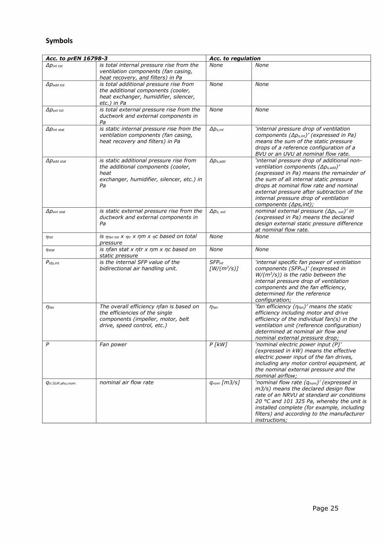
Symbols Acc. to prEN 16798-3 Acc. to regulation
Δpint tot is total internal pressure rise from the ventilation components (fan casing, heat recovery, and filters) in Pa
None None
Δpadd tot is total additional pressure rise from the additional components (cooler, heat exchanger, humidifier, silencer, etc.) in Pa
None None
Δpext tot is total external pressure rise from the
ductwork and external components in Pa
None None
Δpint stat is static internal pressure rise from the ventilation components (fan casing, heat recovery and filters) in Pa
Δps,int ‘internal pressure drop of ventilation components (Δps,int)’ (expressed in Pa) means the sum of the static pressure drops of a reference configuration of a BVU or an UVU at nominal flow rate.
Δpadd stat is static additional pressure rise from the additional components (cooler, heat exchanger, humidifier, silencer, etc.) in Pa
Δps,add ‘internal pressure drop of additional non-ventilation components (Δps,add)’ (expressed in Pa) means the remainder of the sum of all internal static pressure drops at nominal flow rate and nominal external pressure after subtraction of the internal pressure drop of ventilation components (Δps,int);
Δpext stat is static external pressure rise from the ductwork and external components in Pa
Δps, ext nominal external pressure (Δps, ext)’ in (expressed in Pa) means the declared design external static pressure difference at nominal flow rate.
ηtot is ηfan tot x ηtr x ηm x ηc based on total
pressure None None
ηstat is ηfan stat x ηtr x ηm x ηc based on static pressure
None None
Psfp,int is the internal SFP value of the bidirectional air handling unit.
SFPint [W/(m3/s)]
‘internal specific fan power of ventilation components (SFPint)’ (expressed in W/(m3/s)) is the ratio between the
internal pressure drop of ventilation components and the fan efficiency, determined for the reference configuration;
ηfan The overall efficiency ηfan is based on the efficiencies of the single components (impeller, motor, belt drive, speed control, etc.)
ηfan ‘fan efficiency (ηfan)’ means the static efficiency including motor and drive efficiency of the individual fan(s) in the ventilation unit (reference configuration) determined at nominal air flow and nominal external pressure drop;
P Fan power P [kW] ‘nominal electric power input (P)’ (expressed in kW) means the effective electric power input of the fan drives, including any motor control equipment, at the nominal external pressure and the nominal airflow;
qV;SUP;ahu;nom. nominal air flow rate qnom [m3/s] ‘nominal flow rate (qnom)’ (expressed in m3/s) means the declared design flow rate of an NRVU at standard air conditions 20 °C and 101 325 Pa, whereby the unit is installed complete (for example, including filters) and according to the manufacturer instructions;
Page 26
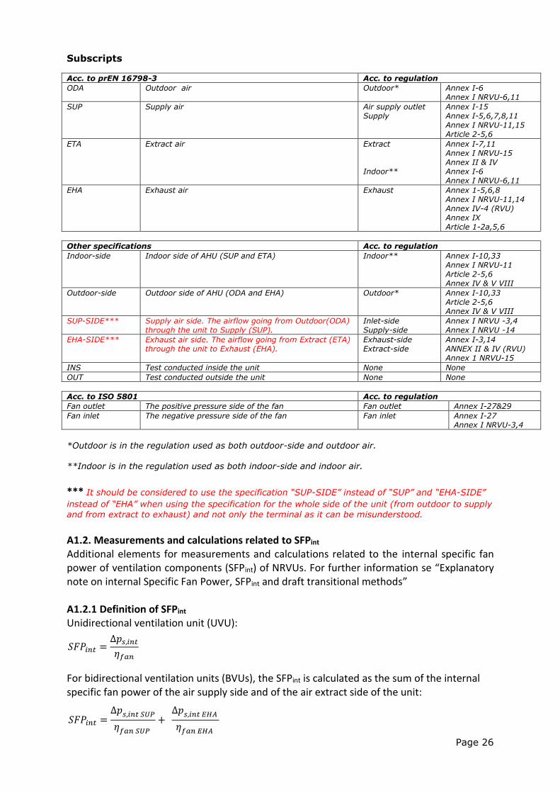
Subscripts
Acc. to prEN 16798-3 Acc. to regulation
ODA Outdoor air Outdoor* Annex I-6 Annex I NRVU-6,11
SUP Supply air Air supply outlet Supply
Annex I-15 Annex I-5,6,7,8,11 Annex I NRVU-11,15 Article 2-5,6
ETA Extract air Extract Indoor**
Annex I-7,11 Annex I NRVU-15 Annex II & IV Annex I-6 Annex I NRVU-6,11
EHA Exhaust air Exhaust Annex 1-5,6,8 Annex I NRVU-11,14 Annex IV-4 (RVU) Annex IX Article 1-2a,5,6
Other specifications Acc. to regulation
Indoor-side Indoor side of AHU (SUP and ETA) Indoor** Annex I-10,33 Annex I NRVU-11 Article 2-5,6 Annex IV & V VIII
Outdoor-side Outdoor side of AHU (ODA and EHA) Outdoor* Annex I-10,33 Article 2-5,6 Annex IV & V VIII
SUP-SIDE*** Supply air side. The airflow going from Outdoor(ODA) through the unit to Supply (SUP).
Inlet-side Supply-side
Annex I NRVU -3,4 Annex I NRVU -14
EHA-SIDE*** Exhaust air side. The airflow going from Extract (ETA) through the unit to Exhaust (EHA).
Exhaust-side Extract-side
Annex I-3,14 ANNEX II & IV (RVU) Annex 1 NRVU-15
INS Test conducted inside the unit None None
OUT Test conducted outside the unit None None
Acc. to ISO 5801 Acc. to regulation
Fan outlet The positive pressure side of the fan Fan outlet Annex I-27&29
Fan inlet The negative pressure side of the fan Fan inlet Annex I-27 Annex I NRVU-3,4
*Outdoor is in the regulation used as both outdoor-side and outdoor air. **Indoor is in the regulation used as both indoor-side and indoor air. *** It should be considered to use the specification “SUP-SIDE” instead of “SUP” and “EHA-SIDE”
instead of “EHA” when using the specification for the whole side of the unit (from outdoor to supply
and from extract to exhaust) and not only the terminal as it can be misunderstood. A1.2. Measurements and calculations related to SFPint Additional elements for measurements and calculations related to the internal specific fan power of ventilation components (SFPint) of NRVUs. For further information se “Explanatory note on internal Specific Fan Power, SFPint and draft transitional methods” A1.2.1 Definition of SFPint
Unidirectional ventilation unit (UVU): For bidirectional ventilation units (BVUs), the SFPint is calculated as the sum of the internal specific fan power of the air supply side and of the air extract side of the unit:
𝑆𝐹𝑃𝑖𝑛𝑡 =∆𝑝𝑠,𝑖𝑛𝑡𝜂𝑓𝑎𝑛
𝑆𝐹𝑃𝑖𝑛𝑡 =∆𝑝𝑠,𝑖𝑛𝑡 𝑆𝑈𝑃
𝜂𝑓𝑎𝑛 𝑆𝑈𝑃
+ ∆𝑝𝑠,𝑖𝑛𝑡 𝐸𝐻𝐴
𝜂𝑓𝑎𝑛 𝐸𝐻𝐴
Page 27
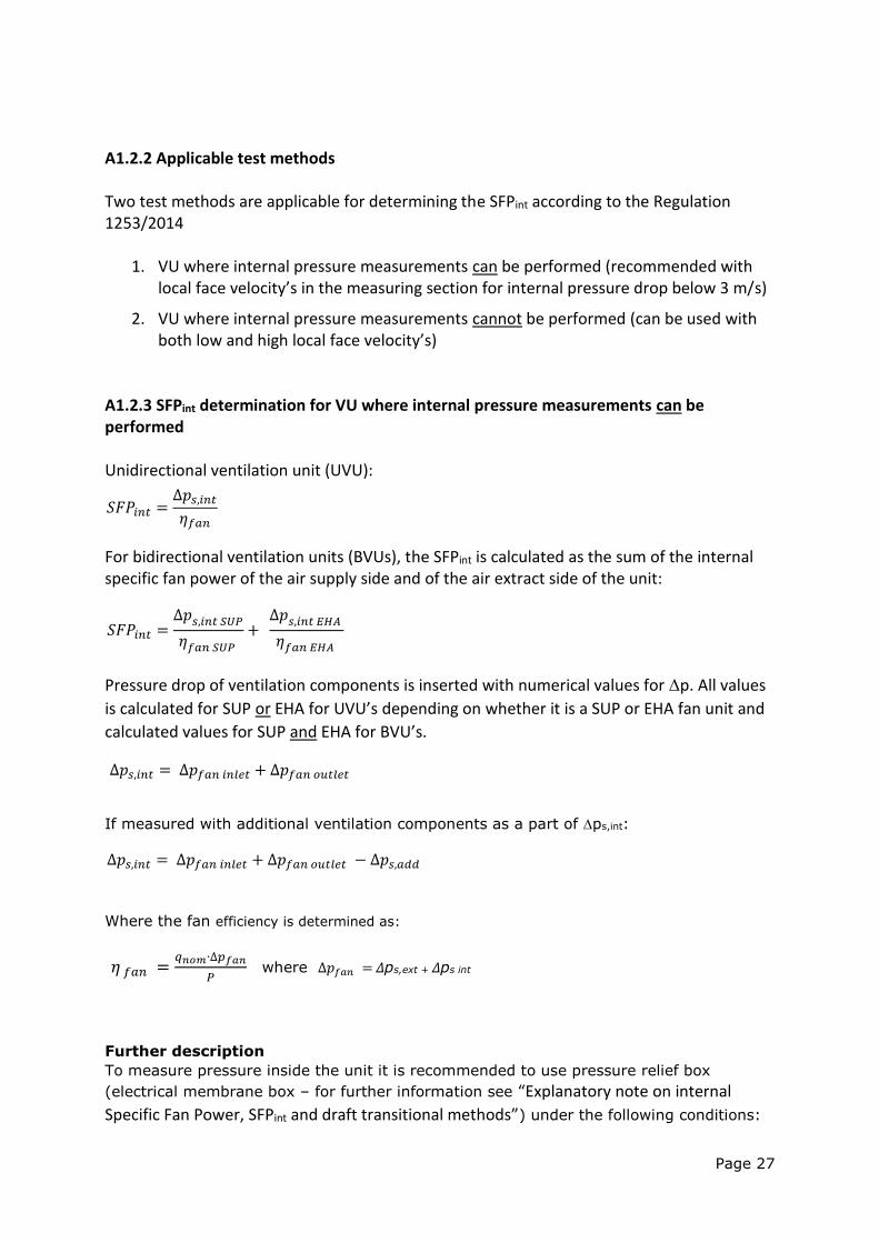
A1.2.2 Applicable test methods Two test methods are applicable for determining the SFPint according to the Regulation 1253/2014
1. VU where internal pressure measurements can be performed (recommended with local face velocity’s in the measuring section for internal pressure drop below 3 m/s)
2. VU where internal pressure measurements cannot be performed (can be used with both low and high local face velocity’s)
A1.2.3 SFPint determination for VU where internal pressure measurements can be performed Unidirectional ventilation unit (UVU): For bidirectional ventilation units (BVUs), the SFPint is calculated as the sum of the internal specific fan power of the air supply side and of the air extract side of the unit:
Pressure drop of ventilation components is inserted with numerical values for p. All values
is calculated for SUP or EHA for UVU’s depending on whether it is a SUP or EHA fan unit and
calculated values for SUP and EHA for BVU’s.
If measured with additional ventilation components as a part of ps,int:
Where the fan efficiency is determined as:
𝜂 𝑓𝑎𝑛 =𝑞𝑛𝑜𝑚∙∆𝑝𝑓𝑎𝑛
𝑃 where ∆𝑝𝑓𝑎𝑛 = Δps,ext + Δps int
Further description
To measure pressure inside the unit it is recommended to use pressure relief box
(electrical membrane box – for further information see “Explanatory note on internal
Specific Fan Power, SFPint and draft transitional methods”) under the following conditions:
𝑆𝐹𝑃𝑖𝑛𝑡 =∆𝑝𝑠,𝑖𝑛𝑡𝜂𝑓𝑎𝑛
𝑆𝐹𝑃𝑖𝑛𝑡 =∆𝑝𝑠,𝑖𝑛𝑡 𝑆𝑈𝑃
𝜂𝑓𝑎𝑛 𝑆𝑈𝑃
+ ∆𝑝𝑠,𝑖𝑛𝑡 𝐸𝐻𝐴
𝜂𝑓𝑎𝑛 𝐸𝐻𝐴
∆𝑝𝑠,𝑖𝑛𝑡 = ∆𝑝𝑓𝑎𝑛 𝑖𝑛𝑙𝑒𝑡 + ∆𝑝𝑓𝑎𝑛 𝑜𝑢𝑡𝑙𝑒𝑡
∆𝑝𝑠,𝑖𝑛𝑡 = ∆𝑝𝑓𝑎𝑛 𝑖𝑛𝑙𝑒𝑡 + ∆𝑝𝑓𝑎𝑛 𝑜𝑢𝑡𝑙𝑒𝑡 − ∆𝑝𝑠,𝑎𝑑𝑑
Page 28
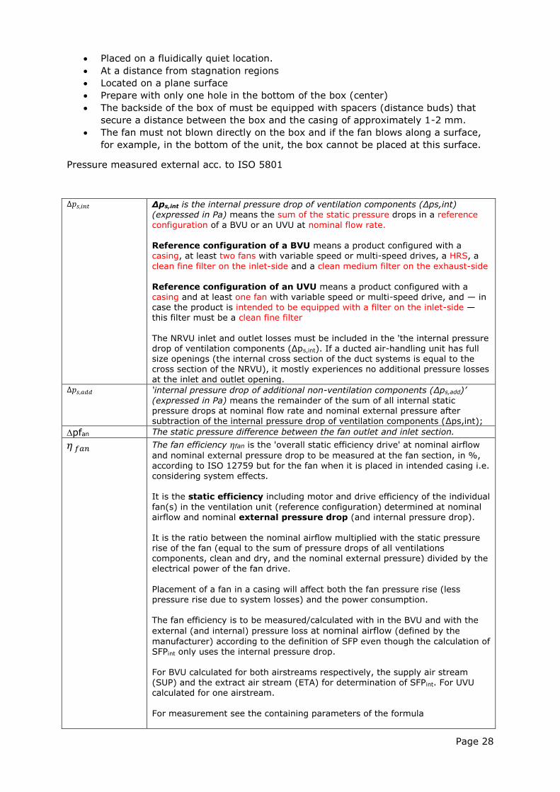
Placed on a fluidically quiet location.
At a distance from stagnation regions
Located on a plane surface
Prepare with only one hole in the bottom of the box (center)
The backside of the box of must be equipped with spacers (distance buds) that
secure a distance between the box and the casing of approximately 1-2 mm.
The fan must not blown directly on the box and if the fan blows along a surface,
for example, in the bottom of the unit, the box cannot be placed at this surface.
Pressure measured external acc. to ISO 5801
∆𝑝𝑠,𝑖𝑛𝑡 Δps,int is the internal pressure drop of ventilation components (Δps,int) (expressed in Pa) means the sum of the static pressure drops in a reference
configuration of a BVU or an UVU at nominal flow rate. Reference configuration of a BVU means a product configured with a casing, at least two fans with variable speed or multi-speed drives, a HRS, a
clean fine filter on the inlet-side and a clean medium filter on the exhaust-side Reference configuration of an UVU means a product configured with a casing and at least one fan with variable speed or multi-speed drive, and — in case the product is intended to be equipped with a filter on the inlet-side — this filter must be a clean fine filter
The NRVU inlet and outlet losses must be included in the 'the internal pressure drop of ventilation components (Δps,int). If a ducted air-handling unit has full size openings (the internal cross section of the duct systems is equal to the cross section of the NRVU), it mostly experiences no additional pressure losses
at the inlet and outlet opening. ∆𝑝𝑠,𝑎𝑑𝑑 ‘internal pressure drop of additional non-ventilation components (Δps,add)’
(expressed in Pa) means the remainder of the sum of all internal static pressure drops at nominal flow rate and nominal external pressure after subtraction of the internal pressure drop of ventilation components (Δps,int);
pfan The static pressure difference between the fan outlet and inlet section.
𝜂 𝑓𝑎𝑛 The fan efficiency ηfan is the 'overall static efficiency drive' at nominal airflow
and nominal external pressure drop to be measured at the fan section, in %, according to ISO 12759 but for the fan when it is placed in intended casing i.e. considering system effects. It is the static efficiency including motor and drive efficiency of the individual
fan(s) in the ventilation unit (reference configuration) determined at nominal airflow and nominal external pressure drop (and internal pressure drop).
It is the ratio between the nominal airflow multiplied with the static pressure rise of the fan (equal to the sum of pressure drops of all ventilations components, clean and dry, and the nominal external pressure) divided by the electrical power of the fan drive.
Placement of a fan in a casing will affect both the fan pressure rise (less pressure rise due to system losses) and the power consumption. The fan efficiency is to be measured/calculated with in the BVU and with the
external (and internal) pressure loss at nominal airflow (defined by the
manufacturer) according to the definition of SFP even though the calculation of SFPint only uses the internal pressure drop.
For BVU calculated for both airstreams respectively, the supply air stream (SUP) and the extract air stream (ETA) for determination of SFPint. For UVU calculated for one airstream.
For measurement see the containing parameters of the formula
Page 29
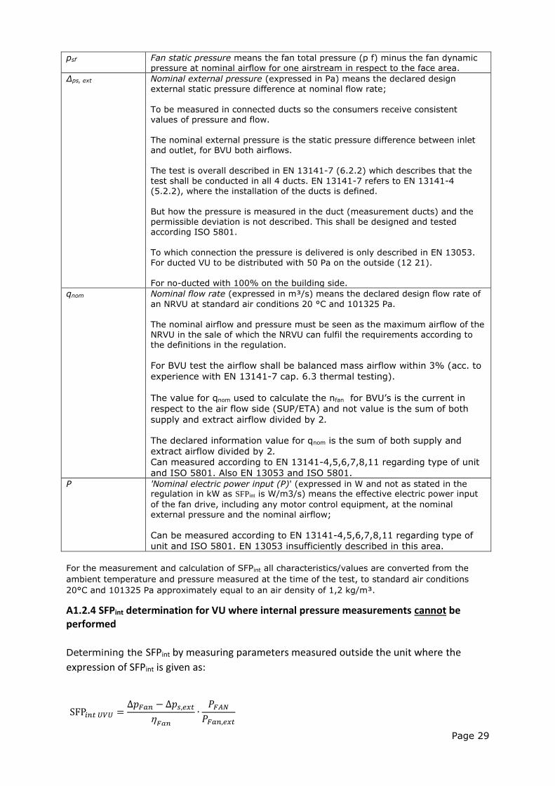
psf Fan static pressure means the fan total pressure (p f) minus the fan dynamic pressure at nominal airflow for one airstream in respect to the face area.
Δps, ext Nominal external pressure (expressed in Pa) means the declared design external static pressure difference at nominal flow rate;
To be measured in connected ducts so the consumers receive consistent values of pressure and flow. The nominal external pressure is the static pressure difference between inlet and outlet, for BVU both airflows. The test is overall described in EN 13141-7 (6.2.2) which describes that the
test shall be conducted in all 4 ducts. EN 13141-7 refers to EN 13141-4 (5.2.2), where the installation of the ducts is defined. But how the pressure is measured in the duct (measurement ducts) and the
permissible deviation is not described. This shall be designed and tested according ISO 5801.
To which connection the pressure is delivered is only described in EN 13053. For ducted VU to be distributed with 50 Pa on the outside (12 21). For no-ducted with 100% on the building side.
qnom Nominal flow rate (expressed in m³/s) means the declared design flow rate of
an NRVU at standard air conditions 20 °C and 101325 Pa. The nominal airflow and pressure must be seen as the maximum airflow of the NRVU in the sale of which the NRVU can fulfil the requirements according to the definitions in the regulation.
For BVU test the airflow shall be balanced mass airflow within 3% (acc. to
experience with EN 13141-7 cap. 6.3 thermal testing).
The value for qnom used to calculate the nfan for BVU’s is the current in
respect to the air flow side (SUP/ETA) and not value is the sum of both
supply and extract airflow divided by 2.
The declared information value for qnom is the sum of both supply and
extract airflow divided by 2.
Can measured according to EN 13141-4,5,6,7,8,11 regarding type of unit
and ISO 5801. Also EN 13053 and ISO 5801.
P 'Nominal electric power input (P)' (expressed in W and not as stated in the regulation in kW as SFPint is W/m3/s) means the effective electric power input
of the fan drive, including any motor control equipment, at the nominal external pressure and the nominal airflow;
Can be measured according to EN 13141-4,5,6,7,8,11 regarding type of
unit and ISO 5801. EN 13053 insufficiently described in this area.
For the measurement and calculation of SFPint all characteristics/values are converted from the
ambient temperature and pressure measured at the time of the test, to standard air conditions
20°C and 101325 Pa approximately equal to an air density of 1,2 kg/m³.
A1.2.4 SFPint determination for VU where internal pressure measurements cannot be performed
Determining the SFPint by measuring parameters measured outside the unit where the
expression of SFPint is given as:
SFP𝑖𝑛𝑡 𝑈𝑉𝑈 =
∆𝑝𝐹𝑎𝑛 − ∆𝑝𝑠,𝑒𝑥𝑡𝐹𝑎𝑛
∙𝑃𝐹𝐴𝑁
𝑃𝐹𝑎𝑛,𝑒𝑥𝑡
Page 30
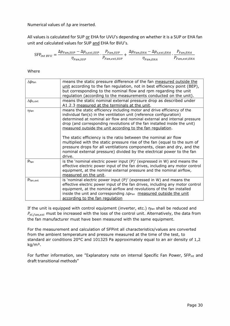
Numerical values of p are inserted.
All values is calculated for SUP or EHA for UVU’s depending on whether it is a SUP or EHA fan
unit and calculated values for SUP and EHA for BVU’s.
Where
pfan means the static pressure difference of the fan measured outside the
unit according to the fan regulation, not in best efficiency point (BEP),
but corresponding to the nominal flow and rpm regarding the unit
regulation (according to the measurements conducted on the unit).
ps,ext means the static nominal external pressure drop as described under
A1.2.3 measured at the terminals at the unit.
fan means the static efficiency including motor and drive efficiency of the
individual fan(s) in the ventilation unit (reference configuration)
determined at nominal air flow and nominal external and internal pressure
drop (and corresponding revolutions of the fan installed inside the unit)
measured outside the unit according to the fan regulation.
The static efficiency is the ratio between the nominal air flow
multiplied with the static pressure rise of the fan (equal to the sum of
pressure drops for all ventilations components, clean and dry, and the
nominal external pressure) divided by the electrical power to the fan
drive.
Pfan is the ‘nominal electric power input (P)’ (expressed in W) and means the
effective electric power input of the fan drives, including any motor control
equipment, at the nominal external pressure and the nominal airflow,
measured on the unit.
Pfan,ext is ‘nominal electric power input (P)’ (expressed in W) and means the
effective electric power input of the fan drives, including any motor control
equipment, at the nominal airflow and revolutions of the fan installed
inside the unit and corresponding pFan measured outside the unit
according to the fan regulation
If the unit is equipped with control equipment (inverter, etc.) ηfan shall be reduced and
𝑃𝑒𝑙,𝑓𝑎𝑛,𝑒𝑥𝑡 must be increased with the loss of the control unit. Alternatively, the data from
the fan manufacturer must have been measured with the same equipment.
For the measurement and calculation of SFPint all characteristics/values are converted
from the ambient temperature and pressure measured at the time of the test, to
standard air conditions 20°C and 101325 Pa approximately equal to an air density of 1,2
kg/m³.
For further information, see “Explanatory note on internal Specific Fan Power, SFPint and draft transitional methods”
SFP𝑖𝑛𝑡 𝐵𝑉𝑈 =∆𝑝𝐹𝑎𝑛,𝑆𝑈𝑃 − ∆𝑝𝑠,𝑒𝑥𝑡,𝑆𝑈𝑃
𝐹𝑎𝑛,𝑆𝑈𝑃∙
𝑃𝐹𝑎𝑛,𝑆𝑈𝑃𝑃𝐹𝑎𝑛,𝑒𝑥𝑡,𝑆𝑈𝑃
+ ∆𝑝𝐹𝑎𝑛,𝐸𝐻𝐴 − ∆𝑝𝑠,𝑒𝑥𝑡,𝐸𝐻𝐴
𝐹𝑎𝑛,𝐸𝐻𝐴∙
𝑃𝐹𝑎𝑛,𝐸𝐻𝐴𝑃𝐹𝑎𝑛,𝑒𝑥𝑡,𝐸𝐻𝐴