exploiting multicore architectures for physically based simulation … · exploiting multicore...
TRANSCRIPT
Exploiting Multicore Architectures for Physically
Based Simulation of Deformable Objects in Virtual
Environments
Lenka Jerabkova1 Christian Terboven2 Samuel Sarholz2 Torsten Kuhlen1
Christian Bischof3
1Virtual Reality Group, RWTH Aachen University, Germany2Center for Computing and Communication, RWTH Aachen University, Germany
3Institute for Scientific Computing, RWTH Aachen University, Germany
Abstract: Physically based simulation is an indispensable component of many interactive
virtual environments. The main challenge of virtual reality applications is the realtime re-
quirement. Advanced simulation methods as, e.g., the finite elements method (FEM) require
significant computational power. However, the performance increases due to higher clock
speed are tapering off. Instead, the compute power is increased by replicating processing
units, making parallel computing a necessity for all performance demanding applications.
In this paper we analyze the runtime and scalability of a dynamic FEM simulation on
dualcore and quadcore architectures. Methods for both small and large deformation simula-
tion are tested and parallelized using OpenMP. The algorithms significantly profit from the
multicore architectures, with minimal changes to the serial code.
Keywords: multicore architectures, shared memory parallelization, physically based mod-
eling, finite elements method, virtual reality
1 Introduction
In the past, a lot of effort has been invested to make computer generated virtual environments
look realistic. Physically based modeling (PBM) is the next step toward making virtual
objects behave realistic. The users are familiar with the behavior of objects in the real world,
therefore providing ’real physics’ in the virtual environment allows for an intuitive interaction
with the virtual objects. There is a wide range of application areas that benefit from PBM,
for example assembly simulation, robotics, training and teaching (medical, military, sports),
and entertainment. Existing methods for the simulation of rigid body dynamics, deformable
objects and fluids have been adapted from the computational engineering sciences. The
main challenge of virtual reality applications is the realtime requirement, meaning that
the time needed to simulate a time step of a dynamic simulation must be shorter than
the time step itself. In the computing industry, performance increases due to higher clock
speed are tapering off. Instead, the compute power is increased by replicating processing
units (multicore architectures). In order to fully utilize all computational resources, parallel
computing is necessary even for desktop computers.
In this paper, we analyze the most commonly used approaches for physically based sim-
ulation of deformable objects from the parallelization point of view with special focus on
multicore architectures. In section 2 we give an overview of related work, section 4 reviews
the governing equations of the dynamic finite element (FE) simulation. We describe our test
cases in section 5 and the parallelization of the dynamic FE simulation using OpenMP in
section 6. We introduce the hardware architectures used for testing in section 3 and present
the results in section 7. The paper closes with a conclusion and outlook.
2 Related Work
[NMK+05] provide an overview of physically based deformable models in computer graphics.
The goal of an interactive physical simulation as used in games or virtual environments is the
visually plausible behavior of the simulated objects. Interactivity and stability of the simu-
lation are necessary conditions, good accuracy is desirable. Several solutions utilizing special
hardware including GPUs [OLG+05, GEW05], the IBM Cell Broadband Engine [DMB+06]
and the AGEIA PhysX processor [Age06] for the performance optimization of the physical
simulation of rigid or deformable objects have been proposed recently. However, in order
to use the hardware acceleration, both the simulation code and data structures have to be
substantially redesigned in order to map to the specific hardware, which is a nontrivial task
requiring special and deep knowledge of the hardware architecture used. Moreover, the end
users have to purchase a specific hardware in order to be able to use the optimizations.
Another promising strategy is the employment of general purpose multicore architectures
[OH05, SL05] as, e.g., the AMD Opteron or the Intel Xeon dualcore processors allowing
for parallel processing of multiple tasks. [TPB07] present a parallelization approach for
cloth simulation on an AMD Opteron machine with two dualcore processors. They use
parallelization techniques that are typically used on distributed memory systems (domain
decomposition followed by a matrix restructuring). They designed an own multithreaded
parallel programming model. The OpenMP standard [OMP05] offers a shared memory
parallelization model for the C/C++ and Fortran programming languages, which are the
most commonly used languages in computational engineering sciences. Compared to lower-
level parallelization approaches as, e.g., Posix-Threads, OpenMP requires the least design
changes of an existing serial code.
In this work, we analyze the linear finite elements method (FEM) as well as the coro-
tational FEM approaches. The linear FEM with constant parameters is the simplest FEM
based approach. However, it is only suitable for small deformations. For large deformations,
the simulation parameters change over time, as they depend on the current deformation
state. Especially, the linear strain measure is not rotationally invariant and therefore leads
to disturbing artifacts whenever the simulated object or its parts change their orientation.
The corotational method was introduced by [MDM+02] and improved by [HS04] and [MG04].
The deformation is decomposed into a rigid rotation part and a pure deformation part avoid-
ing the problem of the classical linear approach. [MG04] achieve interactive simulation rates
for approximately 1,000 tetrahedral elements with both the linear and the corotational meth-
ods on a 1.8 GHz Pentium IV PC. In addition to the elastic deformation they also simulate
plastic deformation (e.g. melting) and fracture. [HS04] compare different approaches for the
simulation of large deformations. They reach a stable simulation with realtime update rates
for approximately 3,000 tetrahedral elements on a 2 GHz Pentium IV PC using the coro-
tational formulation based on the polar decomposition of the deformation gradient. Both
[MG04] and [HS04] use implicit time integration schemes.
In order to profit from recent developments in the computing industry (chip level par-
allelism) and to allow for larger datasets to be handled in realtime, we parallelized the
algorithms mentioned above and analyzed the runtime behavior and scalability. Here we
present an approach that uses several processors or cores in one computer that share the
same memory. As will be described in the following, the presented solution requires only
minimal changes to the source code and the algorithms do not need to be modified at all.
Nonetheless, significant improvements on commodity architectures can be realized.
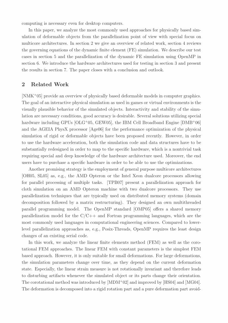
3 Multicore Architectures
We evaluated our parallelized algorithms on two commodity dualcore architectures that
basically differ in how they share the on-chip L2 cache. In addition, we had access to a
prototype of a system with Intel’s quad-core architecture.
Figure 1: The AMD dualcore Opteron system
a) AMD Opteron 875 dualcore processors (Fig. 1), 2.2 GHz, four of which are grouped in
one Sun Fire V40z server. Each core has a 1 MB L2 cache, which is not accessible by
the other cores. This machine has a ccNUMA architecture where the memory access
time depends on the location relative to a processor. On such a system locality is
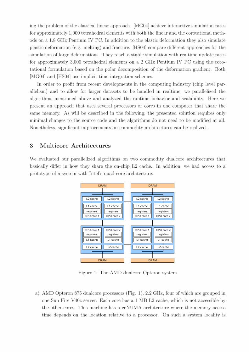
(a) The dualcore Xeon (Woodcrest) system (b) The quadcore Xeon (Clovertown) system
Figure 2: The Intel multicore architectures used for testing.
important in order to achieve high performance. We used the Sun Studio Express
C++ compiler under Solaris.
b) Intel Xeon 5160 dualcore processors (codename Woodcrest, Fig. 2a), 3 GHz, two of
which are grouped in one Dell Power Edge 1950 server. Each processor has a 4 MB
L2 cache shared by its cores. This machine has a flat memory model. We utilized the
Intel 9.1 C++ compiler under Linux.
c) Intel Xeon 5354 quadcore processor (codename Clovertown, Fig. 2b), 2.4 GHz, two of
which are grouped in a server. Every two cores on one chip share 4 MB of L2 cache.
It has to be noted, that we tested on a preproduction version of the processor and the
chipset, which might not achieve the full performance of the final version. We used the
Intel 9.1 C++ compiler under Linux.
High optimization level (-O3) and multifile optimization (-ipo) were used on all systems.
4 The Dynamic Finite Element Simulation
The dynamic FE system is described by the equation
Mu + Du + Ku = f (1)
where u is the vector of nodal displacements, K is the global stiffness matrix, M is the mass
matrix and D is the damping matrix. The stiffness matrix is a sparse symmetric matrix,
where the sparsity pattern corresponds to the elements’ connectivity. The mass and damping
matrices are typically diagonal. The left hand side of equation (1) corresponds to the object’s
internal forces, whereas the right hand side corresponds to the external load. The dimension
of equation (1) is 3N , where N is the number of nodes in the FE mesh.
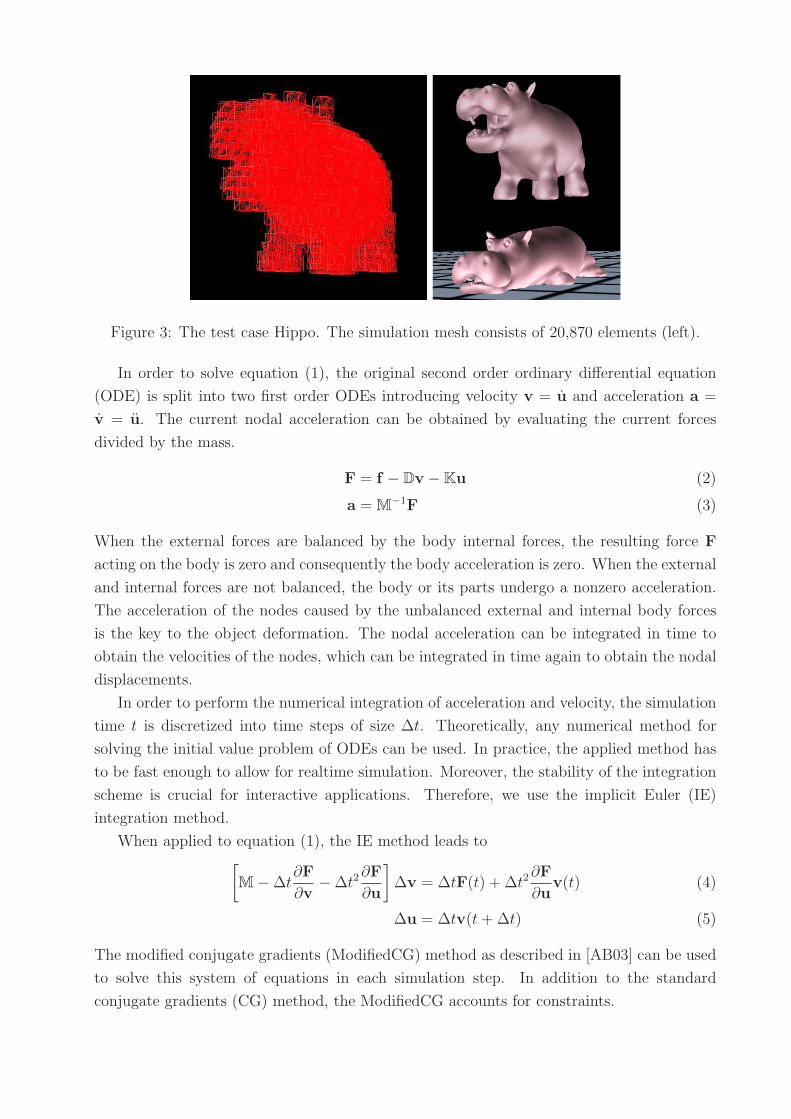
Figure 3: The test case Hippo. The simulation mesh consists of 20,870 elements (left).
In order to solve equation (1), the original second order ordinary differential equation
(ODE) is split into two first order ODEs introducing velocity v = u and acceleration a =
v = u. The current nodal acceleration can be obtained by evaluating the current forces
divided by the mass.
F = f − Dv − Ku (2)
a = M−1F (3)
When the external forces are balanced by the body internal forces, the resulting force F
acting on the body is zero and consequently the body acceleration is zero. When the external
and internal forces are not balanced, the body or its parts undergo a nonzero acceleration.
The acceleration of the nodes caused by the unbalanced external and internal body forces
is the key to the object deformation. The nodal acceleration can be integrated in time to
obtain the velocities of the nodes, which can be integrated in time again to obtain the nodal
displacements.
In order to perform the numerical integration of acceleration and velocity, the simulation
time t is discretized into time steps of size ∆t. Theoretically, any numerical method for
solving the initial value problem of ODEs can be used. In practice, the applied method has
to be fast enough to allow for realtime simulation. Moreover, the stability of the integration
scheme is crucial for interactive applications. Therefore, we use the implicit Euler (IE)
integration method.
When applied to equation (1), the IE method leads to[
M − ∆t∂F
∂v− ∆t2
∂F
∂u
]
∆v = ∆tF(t) + ∆t2∂F
∂uv(t) (4)
∆u = ∆tv(t + ∆t) (5)
The modified conjugate gradients (ModifiedCG) method as described in [AB03] can be used
to solve this system of equations in each simulation step. In addition to the standard
conjugate gradients (CG) method, the ModifiedCG accounts for constraints.
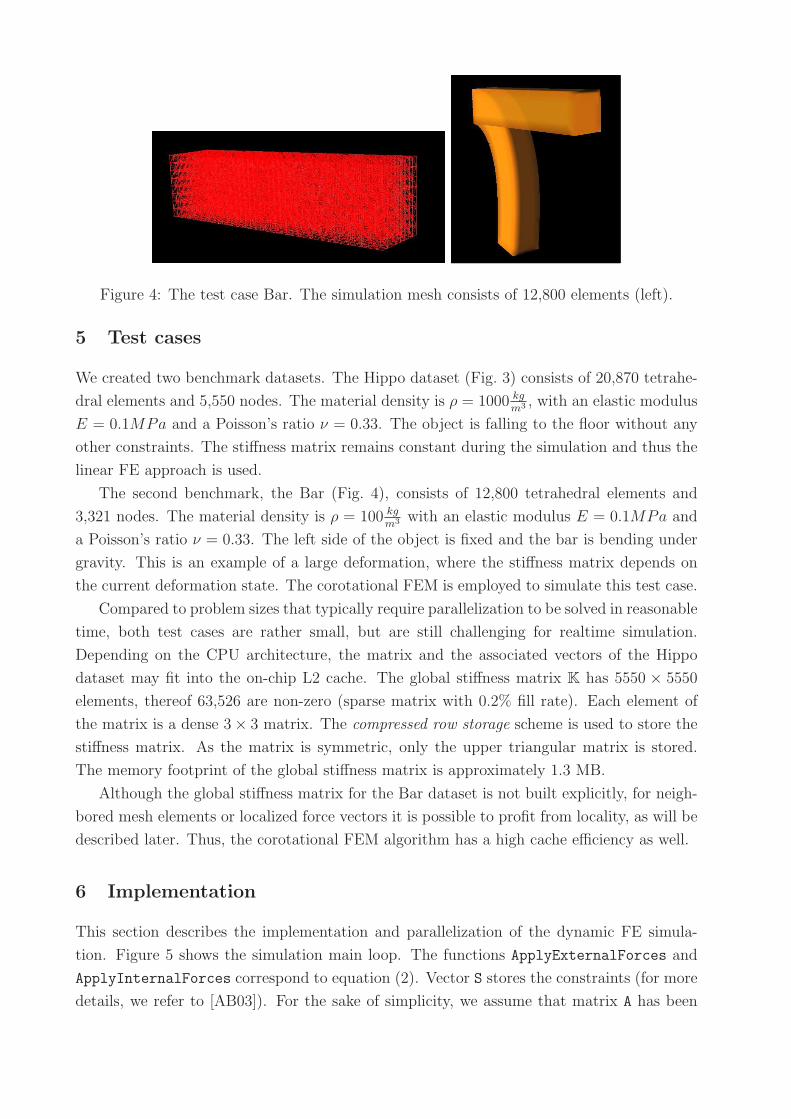
Figure 4: The test case Bar. The simulation mesh consists of 12,800 elements (left).
5 Test cases
We created two benchmark datasets. The Hippo dataset (Fig. 3) consists of 20,870 tetrahe-
dral elements and 5,550 nodes. The material density is ρ = 1000 kg
m3 , with an elastic modulus
E = 0.1MPa and a Poisson’s ratio ν = 0.33. The object is falling to the floor without any
other constraints. The stiffness matrix remains constant during the simulation and thus the
linear FE approach is used.
The second benchmark, the Bar (Fig. 4), consists of 12,800 tetrahedral elements and
3,321 nodes. The material density is ρ = 100 kg
m3 with an elastic modulus E = 0.1MPa and
a Poisson’s ratio ν = 0.33. The left side of the object is fixed and the bar is bending under
gravity. This is an example of a large deformation, where the stiffness matrix depends on
the current deformation state. The corotational FEM is employed to simulate this test case.
Compared to problem sizes that typically require parallelization to be solved in reasonable
time, both test cases are rather small, but are still challenging for realtime simulation.
Depending on the CPU architecture, the matrix and the associated vectors of the Hippo
dataset may fit into the on-chip L2 cache. The global stiffness matrix K has 5550 × 5550
elements, thereof 63,526 are non-zero (sparse matrix with 0.2% fill rate). Each element of
the matrix is a dense 3 × 3 matrix. The compressed row storage scheme is used to store the
stiffness matrix. As the matrix is symmetric, only the upper triangular matrix is stored.
The memory footprint of the global stiffness matrix is approximately 1.3 MB.
Although the global stiffness matrix for the Bar dataset is not built explicitly, for neigh-
bored mesh elements or localized force vectors it is possible to profit from locality, as will be
described later. Thus, the corotational FEM algorithm has a high cache efficiency as well.
6 Implementation
This section describes the implementation and parallelization of the dynamic FE simula-
tion. Figure 5 shows the simulation main loop. The functions ApplyExternalForces and
ApplyInternalForces correspond to equation (2). Vector S stores the constraints (for more
details, we refer to [AB03]). For the sake of simplicity, we assume that matrix A has been
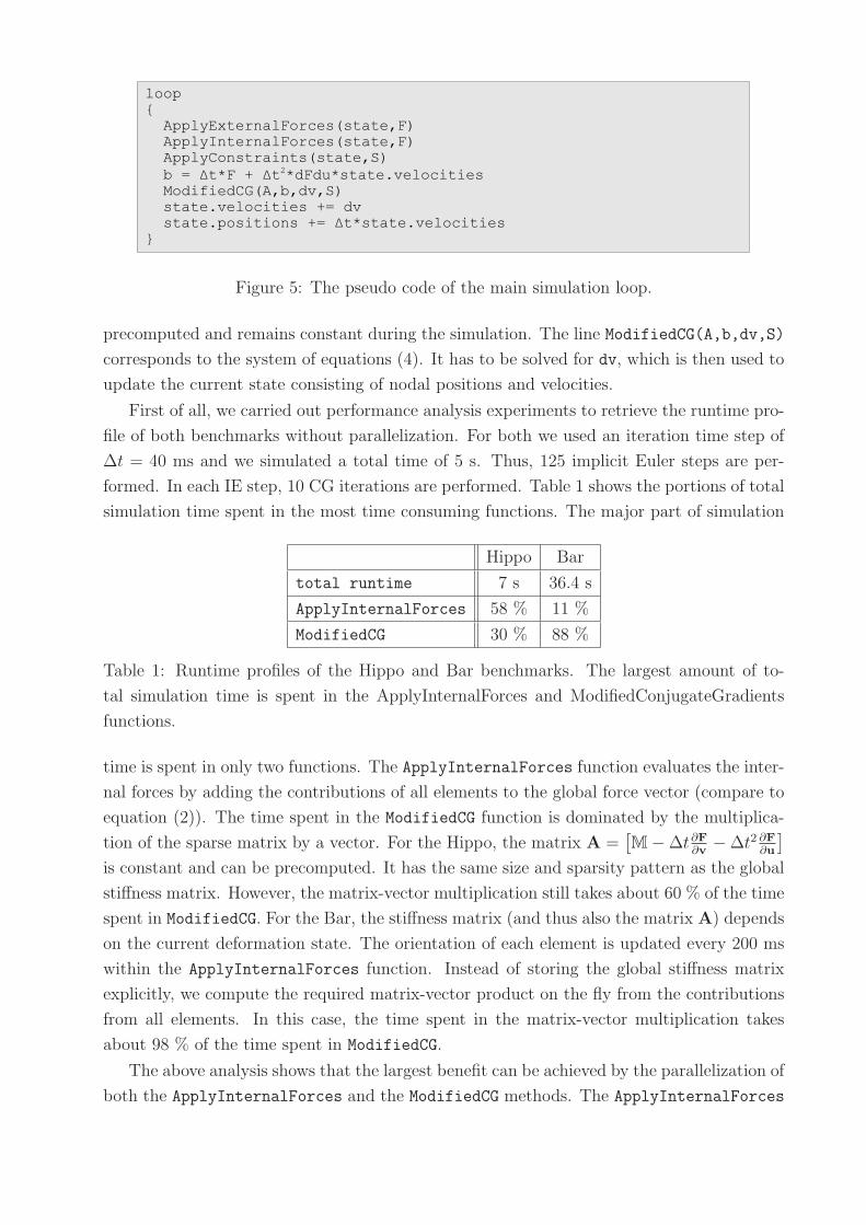
Figure 5: The pseudo code of the main simulation loop.
precomputed and remains constant during the simulation. The line ModifiedCG(A,b,dv,S)
corresponds to the system of equations (4). It has to be solved for dv, which is then used to
update the current state consisting of nodal positions and velocities.
First of all, we carried out performance analysis experiments to retrieve the runtime pro-
file of both benchmarks without parallelization. For both we used an iteration time step of
∆t = 40 ms and we simulated a total time of 5 s. Thus, 125 implicit Euler steps are per-
formed. In each IE step, 10 CG iterations are performed. Table 1 shows the portions of total
simulation time spent in the most time consuming functions. The major part of simulation
Hippo Bar
total runtime 7 s 36.4 s
ApplyInternalForces 58 % 11 %
ModifiedCG 30 % 88 %
Table 1: Runtime profiles of the Hippo and Bar benchmarks. The largest amount of to-
tal simulation time is spent in the ApplyInternalForces and ModifiedConjugateGradients
functions.
time is spent in only two functions. The ApplyInternalForces function evaluates the inter-
nal forces by adding the contributions of all elements to the global force vector (compare to
equation (2)). The time spent in the ModifiedCG function is dominated by the multiplica-
tion of the sparse matrix by a vector. For the Hippo, the matrix A =[
M − ∆t∂F
∂v− ∆t2 ∂F
∂u
]
is constant and can be precomputed. It has the same size and sparsity pattern as the global
stiffness matrix. However, the matrix-vector multiplication still takes about 60 % of the time
spent in ModifiedCG. For the Bar, the stiffness matrix (and thus also the matrix A) depends
on the current deformation state. The orientation of each element is updated every 200 ms
within the ApplyInternalForces function. Instead of storing the global stiffness matrix
explicitly, we compute the required matrix-vector product on the fly from the contributions
from all elements. In this case, the time spent in the matrix-vector multiplication takes
about 98 % of the time spent in ModifiedCG.
The above analysis shows that the largest benefit can be achieved by the parallelization of
both the ApplyInternalForces and the ModifiedCG methods. The ApplyInternalForces
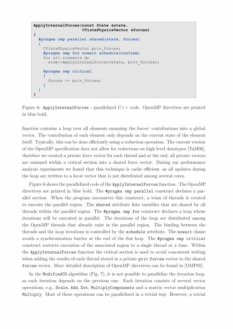
Figure 6: ApplyInternalForces - parallelized C++ code. OpenMP directives are printed
in blue bold.
function contains a loop over all elements summing the forces’ contributions into a global
vector. The contribution of each element only depends on the current state of the element
itself. Typically, this can be done efficiently using a reduction operation. The current version
of the OpenMP specification does not allow for reductions on high level datatypes [TaM06],
therefore we created a private force vector for each thread and at the end, all private vectors
are summed within a critical section into a shared force vector. During our performance
analysis experiments we found that this technique is cache efficient, as all updates during
the loop are written to a local vector that is not distributed among several cores.
Figure 6 shows the parallelized code of the ApplyInternalForces function. The OpenMP
directives are printed in blue bold. The #pragma omp parallel construct declares a par-
allel section. When the program encounters this construct, a team of threads is created
to execute the parallel region. The shared attribute lists variables that are shared by all
threads within the parallel region. The #pragma omp for construct declares a loop whose
iterations will be executed in parallel. The iterations of the loop are distributed among
the OpenMP threads that already exist in the parallel region. The binding between the
threads and the loop iterations is controlled by the schedule attribute. The nowait clause
avoids a synchronization barrier at the end of the for loop. The #pragma omp critical
construct restricts execution of the associated region to a single thread at a time. Within
the ApplyInternalForces function the critical section is used to avoid concurrent writing
when adding the results of each thread stored in a private priv forces vector to the shared
forces vector. More detailed description of OpenMP directives can be found in [OMP05].
In the ModifiedCG algorithm (Fig. 7), it is not possible to parallelize the iteration loop,
as each iteration depends on the previous one. Each iteration consists of several vector
operations, e.g., Scale, Add, Dot, MultiplyComponents and a matrix vector multiplication
Multiply. Most of these operations can be parallelized in a trivial way. However, a trivial
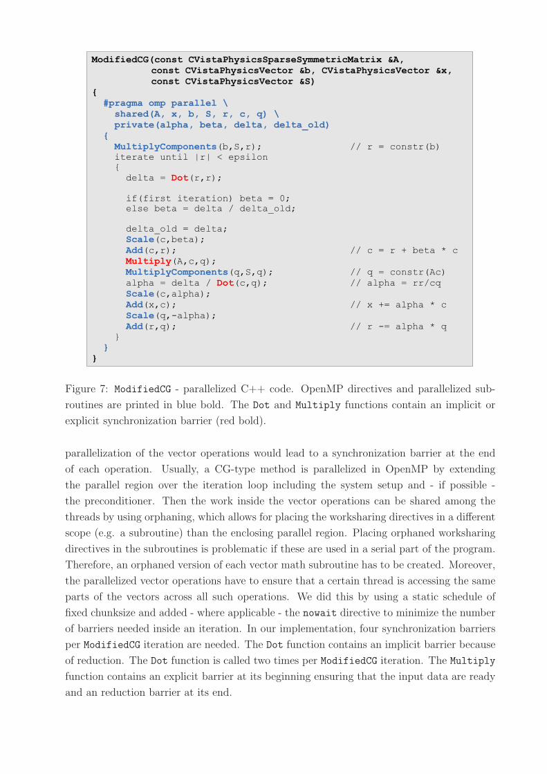
Figure 7: ModifiedCG - parallelized C++ code. OpenMP directives and parallelized sub-
routines are printed in blue bold. The Dot and Multiply functions contain an implicit or
explicit synchronization barrier (red bold).
parallelization of the vector operations would lead to a synchronization barrier at the end
of each operation. Usually, a CG-type method is parallelized in OpenMP by extending
the parallel region over the iteration loop including the system setup and - if possible -
the preconditioner. Then the work inside the vector operations can be shared among the
threads by using orphaning, which allows for placing the worksharing directives in a different
scope (e.g. a subroutine) than the enclosing parallel region. Placing orphaned worksharing
directives in the subroutines is problematic if these are used in a serial part of the program.
Therefore, an orphaned version of each vector math subroutine has to be created. Moreover,
the parallelized vector operations have to ensure that a certain thread is accessing the same
parts of the vectors across all such operations. We did this by using a static schedule of
fixed chunksize and added - where applicable - the nowait directive to minimize the number
of barriers needed inside an iteration. In our implementation, four synchronization barriers
per ModifiedCG iteration are needed. The Dot function contains an implicit barrier because
of reduction. The Dot function is called two times per ModifiedCG iteration. The Multiply
function contains an explicit barrier at its beginning ensuring that the input data are ready
and an reduction barrier at its end.
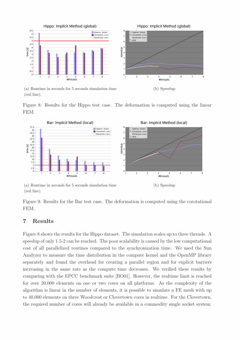
(a) Runtime in seconds for 5 seconds simulation time
(red line).
(b) Speedup
Figure 8: Results for the Hippo test case. The deformation is computed using the linear
FEM.
(a) Runtime in seconds for 5 seconds simulation time
(red line).
(b) Speedup
Figure 9: Results for the Bar test case. The deformation is computed using the corotational
FEM.
7 Results
Figure 8 shows the results for the Hippo dataset. The simulation scales up to three threads. A
speedup of only 1.5-2 can be reached. The poor scalability is caused by the low computational
cost of all parallelized routines compared to the synchronization time. We used the Sun
Analyzer to measure the time distribution in the compute kernel and the OpenMP library
separately and found the overhead for creating a parallel region and for explicit barriers
increasing in the same rate as the compute time decreases. We verified these results by
comparing with the EPCC benchmark suite [BO01]. However, the realtime limit is reached
for over 20,000 elements on one or two cores on all platforms. As the complexity of the
algorithm is linear in the number of elements, it is possible to simulate a FE mesh with up
to 40,000 elements on three Woodcrest or Clovertown cores in realtime. For the Clovertown,
the required number of cores will already be available in a commodity single socket system.
For the Bar benchmark, the computational costs in both the ApplyInternalForces and
the ModifiedCG functions are higher and, therefore, a better scalability can be expected.
Figure 9 shows the results for the Bar dataset. We reached a speedup of up to 6.5 on
eight Clovertown cores and 3.4 on four cores on all platforms. However, the realtime limit
for nearly 13,000 elements has only been reached on the Clovertown platform. With five
OpenMP threads, the Clovertown performance drops down unexpectedly. The effect is
reproducible, but we do not have a substantiated explanation for it. As the complexity of
the algorithm is linear in the number of elements, it is possible to simulate up to 10,500
elements on four Woodcrest cores in realtime. This is a noticeable improvement, compared
to the approx. 3,000 elements that can be simulated in realtime by a serial algorithm.
8 Conclusion and Outlook
The algorithms examined in this work profit from the current development in the computing
industry of placing multiple processing units on one chip. The parallelization of the serial
algorithms was straight forward, only minimal changes to the C++ source code were nec-
essary. On Clovertown, the first quadcore architecture available on the consumer market,
we were able to handle a dataset with 13,000 elements using the corotational FEM for the
simulation of large deformations in realtime. The achieved speedup is comparable to the
values achieved by advanced parallelization techniques as domain decomposition and matrix
rearrangement (cp. [TPB07]).
The methods described in this paper have been integrated into our surgery simulator.
Surgical simulation is one of the most challenging application areas of PBM. In addition to
tissue deformation and its visualization, collision detection and force feedback have to be
processed as well. Moreover, tissue cutting has to be provided. The deformation, visualiza-
tion, collision detection and haptics processes run in parallel, each in a separate thread with
its specific update rate. As can be seen from the results presented above, the computation-
ally most intensive part, the FEM based deformation, significantly profits from multicore
architectures. We expect the surgery simulator system to benefit from upcoming parallel
architectures, that will be multisocket multicore machines, by binding the different software
components to sets of processing units separately.
References
[AB03] Uri M. Ascher and Eddy Boxerman. On the modified conjugate gradient method
in cloth simulation. Visual Computer, 19(7-8):526–531, Dec. 2003.
[Age06] Ageia PhysX. http://www.ageia.com/physx/, 2006. Last visited on June 6,
2007.
[BO01] J. Mark Bull and Darragh O’Neill. A Microbenchmark Suite for OpenMP 2.0. In
Proceedings of the Third European Workshop on OpenMP (EWOMP’01), 2001.
[DMB+06] Bruce D’Amora, Karen Magerlein, Atman Binstock, Ashwini Nanda, and
Bernard Yee. High-performance server systems and the next generation of online
games. IBM Systems Journal, 45(1):103–118, 2006.
[GEW05] Joachim Georgii, Florian Echtler, and Rudiger Westermann. Interactive Simu-
lation of Deformable Bodies on GPUs. In Simulation and Visualisation 2005,
2005.
[HS04] Michael Hauth and Wolfgang Strasser. Corotational Simulation of Deformable
Solids. Journal of the WSCG, 12(1-3):137–145, 2004.
[MDM+02] Matthias Muller, Julie Dorsey, Leonard McMillan, Robert Jagnow, and Barbara
Cutler. Stable Real-Time Deformations. In Proceedings of Siggraph, pages 49 –
54. ACM Press New York, NY, USA, 2002.
[MG04] Matthias Muller and Markus Gross. Interactive Virtual Materials. In GI ’04:
Proceedings of the 2004 conference on Graphics interface, pages 239–246. Cana-
dian Human-Computer Communications Society, 2004.
[NMK+05] Andrew Nealen, Matthias Muller, Richard Keiser, Eddy Boxerman, and Mark
Carlson. Physically Based Deformable Models in Computer Graphics. In Pro-
ceedings of Eurographics, 2005. STAR - State of The Art Report.
[OH05] Kunle Olukotun and Lance Hammond. The future of microprocessors. Queue,
3(7):26–29, 2005.
[OLG+05] John D. Owens, David Luebke, Naga Govindaraju, Mark Harris, Jens Kruger,
Aaron E. Lefohn, and Timothy J. Purcell. A Survey of General-Purpose Com-
putation on Graphics Hardware. In Eurographics ’05, State of the Art Reports,
pages 21–51, 2005.
[OMP05] OpenMP Architecture Reviewer Board. OpenMP Application Program Inter-
face, v2.5, 2005.
[SL05] Herb Sutter and James Larus. Software and the concurrency revolution. Queue,
3(7):54–62, Sept. 2005.
[TaM06] Christian Terboven and Dieter an Mey. OpenMP and C++. In Second Interna-
tional Workshop on OpenMP (IWOMP 2006), 2006.
[TPB07] Bernhard Thomaszewski, Simon Pabst, and Wolfgang Blochinger. Exploiting
Parallelism in Physically-Based Simulations on Multi-Core Processor Architec-
tures. In Proceedings of Eurographics Symposium on Parallel Graphics and Vi-
sualization (EGPGV’07), 2007.