exploiting proprioception in virtual-environment interaction · exploiting proprioception in...
TRANSCRIPT

Exploiting Proprioception inVirtual-Environment Interaction
by
Mark Raymond Mine
A dissertation submitted to the faculty of the University of North Carolina at Chapel Hill inpartial fulfillment of the requirements for the degree of Doctor of Philosophy in theDepartment of Computer Science.
Chapel Hill
1997
Approved by:
_____________________________ __________________________
Dr. Frederick P. Brooks Jr., Advisor Dr. Henry Fuchs
_____________________________ __________________________
Dr. Gary Bishop, Reader Dr. Anselmo Lastra
_____________________________ __________________________
Dr. John Tector, Reader. Dr. Carlo H. Sequin

ii
© 1997Mark Raymond Mine
ALL RIGHTS RESERVED
iii
ABSTRACT
Mark Raymond MineExploiting Proprioception in Virtual-Environment Interaction
(Under the direction of Frederick P. Brooks, Jr.)
Manipulation in immersive virtual environments is difficult partly because users
must do without the haptic contact with real objects they rely on in the real world to orient
themselves and the objects they are manipulating. To compensate for this lack, I propose
exploiting the one real object every user has in a virtual environment, his body. I present a
unified framework for virtual-environment interaction based on proprioception, a person's
sense of the position and orientation of his body and limbs. I describe three forms of
body-relative interaction:
• Direct manipulation—ways to use body sense to help control manipulation
• Physical mnemonics—ways to store/recall information relative to the body
• Gestural actions—ways to use body-relative actions to issue commands
Automatic scaling is a way to bring objects instantly within reach so that users can
manipulate them using proprioceptive cues. Several novel virtual interaction techniques
based upon automatic scaling and our proposed framework of proprioception allow a user
to interact with a virtual world intuitively, efficiently, precisely, and lazily.
Two formal user studies evaluate key aspects of body-relative interaction. The
virtual docking study compares the manipulation of objects co-located with one's hand and
the manipulation of objects at a distance. The widget interaction experiment explores the
differences between interacting with a widget held in one's hand and interacting with a
widget floating in space.
Lessons learned from the integration of body-relative techniques into a real-world
system, the Chapel Hill Immersive Modeling Program (CHIMP), are presented and
discussed.

iv
ACKNOWLEDGMENTS
Thanks to
Frederick P. Brooks Jr., Gary Bishop, Henry Fuchs, Anselmo Lastra, JohnTector, and Carlo H. Sequin for serving on my doctoral dissertation committee;
Frederick P. Brooks Jr., my advisor, for his insights, inspiration, and for making itall so clear;
Gary Bishop for many fruitful years of collaboration and for not minding too muchthat my dissertation didn't have wires and accelerometers coming out of it;
Henry Fuchs for the inspiration of his boundless energy, enthusiasm, and love ofknowledge;
Anselmo Lastra for his kindness, advice, and for keeping Pixel-Planes 5 alive longenough for me to graduate;
Carlo Sequin for asking the hard questions, and for helping me to keep it simple;
John Tector for the many wonderful conversations about architecture and design;
Warren Robinett for leading me to the University of North Carolina;
Rick Zobel for paving the way for my investigations into immersive design;
Robert Zeleznik for his invaluable contributions to this work;
Linda Houseman, Dave Harrison, Todd Gaul, and Peggy Wetzel for all of theirhelp during the years;
Hans Weber and Greg Welch for being such good friends and for the meetings ofthe IHBI at the TOTH1;
Erik Erikson for Vinimini, G2, Speed Racer, and for keeping it fun;
Eliza Graves for the laughter and the smiles;
My parents for all they have done for me through the years;
Dylan for the incredible joy he has brought to my life;
Baby X for the many wonderful years to come;
and most importantly,
Sandra for her unwavering love, support, faith, and devotion, and for, more thananyone else, making it all possible.
Financial support for this work came from the following agencies: Defense AdvancedResearch Projects Agency, Link Foundation, Lockheed Missiles and Space, Inc. (indirectDARPA)
1Institute for Half-Baked Ideas at the Top of the Hill

v
TABLE OF CONTENTS
Page
LIST OF TABLES..................................................... x
LIST OF FIGURES.................................................... xi
LIST OF ABBREVIATIONS ............................................ xiii
Chapter
I . Introduction.................................................... 1
1.1 The Research............................................. 1
1.2 The Challenge............................................ 1
1.3 The Attack............................................... 2
1.4 A Complication........................................... 3
1.5 A Proposal............................................... 5
1.6 Overview................................................ 6
II. Related Work................................................... 8
2.1 3-DoF and 6-DoF Object Manipulation Using 2D Input............ 8
2.2 Object Manipulation Using Higher-Dimensional Input............. 11
2.3 Two-handed Interaction..................................... 14
2.3.1 Example Techniques................................ 14
2.3.2 Theoretical and Experimental Results................... 19
2.4 Manipulating Objects Using Gesture and Voice................... 22
2.5 Systems for Interactive Design................................ 24
2.5.1 Working Through-the-window........................ 25
2.5.2 Working Immersed................................. 30
III. Body-Relative Interaction Techniques................................ 33
3.1 Working Within Arm's Reach................................ 33
3.2 Sample Interaction Techniques................................ 36
3.2.1 Direct Manipulation................................. 36
3.2.1.1 Scaled-World Grab for Manipulation.......... 36
3.2.1.2 Scaled-World Grab for Locomotion........... 38
3.2.2 Physical Mnemonics................................ 38
3.2.2.1 Pull-Down Menus......................... 38
3.2.2.2 Hand-Held Widgets....................... 39
3.2.2.3 FOV-Relative Mode Switching............... 41
3.3.3 Gestural Actions................................... 41
3.3.3.1 Head-Butt Zoom.......................... 41

vi
3.3.3.2 Look-at Menus........................... 43
3.3.3.3 Two-Handed Flying....................... 43
3.3.3.4 Over-the-Shoulder Deletion.................. 44
IV. User Study 1—Virtual Object Docking............................... 46
4.1 Introduction.............................................. 46
4.2 Hypotheses.............................................. 47
4.3 The Experiment........................................... 47
4.3.1 Subjects.......................................... 47
4.3.2 Experimental Platform............................... 47
4.3.3 The Task......................................... 48
4.3.4 Experimental Conditions............................. 49
4.3.5 Experimental Procedure............................. 50
4.4 Results.................................................. 51
4.5 Questionnaire Results....................................... 54
4.6 Discussion............................................... 56
4.7 Conclusion............................................... 56
V. User Study 2—Proprioception and Virtual Widget Interaction............. 58
5.1 Introduction.............................................. 58
5.2 Hypotheses.............................................. 59
5.3 The Experiment........................................... 59
5.3.1 Subjects.......................................... 59
5.3.2 Experimental Platform............................... 60
5.3.3 The Task......................................... 61
5.3.4 Experimental Procedure............................. 62
5.4 Results.................................................. 63
5.5 Questionnaire Results....................................... 64
5.6 Discussion............................................... 65
5.7 Conclusions.............................................. 66
VI. CHIMP—The Chapel Hill Immersive Modeling Program................. 68
6.1 CHIMP Overview......................................... 68
6.2 Managing Modes.......................................... 73
6.2.1 Rotary Tool Chooser................................ 74
6.2.2 Two-Dimensional Control Panels...................... 75
6.2.3 Look-at Menus.................................... 77
6.2.4 Pull-Down Menus.................................. 77
6.3 Object Selection........................................... 78

vii
6.4 Object Manipulation........................................ 81
6.5 Object Generation.......................................... 82
6.6 Constrained Object Manipulation.............................. 83
6.6.1 Co-Located Widgets................................ 83
6.6.2 Hand-Held Widgets................................ 85
6.7 Numeric Input in a Virtual World.............................. 86
VII. Final Words.................................................... 90
7.1 Conclusions.............................................. 90
7.2 Contributions............................................. 91
7.3 Future Work.............................................. 93
Localized Haptic Feedback................................... 93
A. A Review of the State-of-the-Art of Computer-Aided Modeling............ 95
A.1 Introduction.............................................. 95
A.2 Modeling Techniques and Paradigms........................... 96
A.2.1 Input for a Three-Dimensional Task.................... 96
A.2.1.1 Numeric Input............................ 96
A.2.1.2 Relative Input............................. 96
A.2.1.3 2D Interactive Input........................ 97
A.2.2 Output of a Three-Dimensional Space................... 98
A.2.2.1 Format of the Modeling View................ 99
A.2.2.2 Three-Dimensional Visualization: Separate orIntegrated............................... 100
A.2.2.3 Three-Dimensional Visualization: Static orInteractive............................... 101
A.2.2.4 Complications of Two-Dimensional Output..... 101
A.3 Modeling System Capability Comparison....................... 102
A.4 Modeler Reviews Overview.................................. 105
A.5 Archicad................................................. 107
A.5.1 Overview......................................... 107
A.5.2 Model Creation.................................... 108
A.5.3 Model Modification................................. 108
A.5.4 Model Interaction/Visualization........................ 109
A.5.5 Manual .......................................... 109
A.5.6 Comments/Impressions.............................. 110
A.6 AutoCAD................................................ 111
A.6.1 Overview......................................... 111
A.6.2 Model Creation.................................... 112
viii
A.6.3 Model Modification................................. 113
A.6.4 Model Interaction/Visualization........................ 114
A.6.5 Manual .......................................... 114
A.6.6 Comments/Impressions.............................. 114
A.7 DesignWorkshop.......................................... 115
A.7.1 Overview......................................... 115
A.7.2 Model Creation.................................... 116
A.7.3 Model Modification................................. 117
A.7.4 Model Interaction/Visualization........................ 117
A.7.5 Manual .......................................... 118
A.7.6 Comments/Impressions.............................. 118
A.8 Designer's Workbench...................................... 119
A.8.1 Overview......................................... 119
A.8.2 Model Creation.................................... 120
A.8.3 Model Modification................................. 121
A.8.4 Model Interaction/Visualization........................ 122
A.8.5 Manual .......................................... 122
A.8.6 Comments/Impressions.............................. 122
A.9 Form-Z.................................................. 123
A.9.1 Overview......................................... 123
A.9.2 Model Creation.................................... 124
A.9.3 Model Modification................................. 125
A.9.4 Model Interaction/Visualization........................ 125
A.9.5 Manual .......................................... 126
A.9.6 Comments/Impressions.............................. 126
A.10 IGRIP .................................................. 128
A.10.1 Overview......................................... 128
A.10.2 Model Creation.................................... 130
A.10.3 Model Modification................................. 130
A.10.4 Model Interaction/Visualization........................ 131
A.10.5 Manual .......................................... 131
A.10.6 Comments/Impressions.............................. 132
A.11 Minicad+4............................................... 133
A.11.1 Overview......................................... 133
A.11.2 Model Creation.................................... 134
A.11.3 Model Modification................................. 135

ix
A.11.4 Model Interaction/Visualization........................ 136
A.11.5 Manual .......................................... 136
A.11.6 Comments/Impressions.............................. 136
A.12 MultiGen ................................................ 138
A.12.1 Overview......................................... 138
A.12.2 Model Creation.................................... 139
A.12.3 Model Modification................................. 140
A.12.4 Model Interaction/Visualization........................ 140
A.12.5 Manual .......................................... 141
A.12.6 Comments/Impressions.............................. 141
A.13 Sculpt 3D................................................ 143
A.13.1 Overview......................................... 143
A.13.2 Model Creation.................................... 144
A.13.3 Model Modification................................. 145
A.13.4 Model Interaction/Visualization........................ 145
A.13.5 Manual .......................................... 146
A.13.6 Comments/Impressions.............................. 146
A.14 Upfront ................................................. 148
A.14.1 Overview......................................... 148
A.14.2 Model Creation.................................... 149
A.14.3 Model Modification................................. 150
A.14.4 Model Interaction/Visualization........................ 150
A.14.5 Manual .......................................... 151
A.14.6 Comments/Impressions.............................. 151
A.15 WalkThrough............................................. 153
A.15.1 Overview......................................... 153
A.15.2 Model Creation.................................... 154
A.15.3 Model Modification................................. 154
A.15.4 Model Interaction/Visualization........................ 155
A.15.5 Manual .......................................... 155
A.15.6 Comments/Impressions.............................. 156
B. References..................................................... 157

x
LIST OF TABLES
Table 1.1: Successful virtual-world application domains..................... 3
Table 2.1: Interactive design systems input/output comparison................ 25
Table 4.1: Mean time of trial completion by experimental condition............ 52
Table 4.2: Mean questionnaire results by technique......................... 54
Table 4.3: F statistic and significance by questionnaire category............... 54
Table 4.4: Co-located vs. fixed-offset, F statistic and significance byquestionnaire category...................................... 55
Table 4.5: Co-located vs. variable-offset, F statistic and significance byquestionnaire category...................................... 55
Table 4.6: Fixed-offset vs. variable-offset, F statistic and significance byquestionnaire category...................................... 55
Table 5.1: Mean positional accuracy by experimental condition............... 63
Table 5.2: Mean questionnaire results by technique......................... 65
Table 5.3: F statistic and significance by questionnaire category............... 65
Table 6.1: CHIMP system overview.................................... 70
Table 6.2: CHIMP's hand-held widgets................................. 71
Table 6.3: CHIMP's control panels..................................... 72
Table A.1: Modeling packages reviewed................................. 95
Table A.2: Modeling system capability comparison......................... 103
Table A.3: Modeling system paradigms.................................. 106
xi
LIST OF FIGURES
Figure 2.1: Nielson's triad cursor....................................... 8
Figure 2.2: Constrained geometric transformation using widgets............... 10
Figure 2.3: Using object associations.................................... 11
Figure 2.4: The Rockin' Mouse........................................ 12
Figure 2.5: Zhai et al.'s framework for the study of multi-degree-of-freedommanipulation schemes....................................... 13
Figure 2.6: Layers in a toolglass system.................................. 14
Figure 2.7: Using toolglasses, two-hands, and transparency in T3............. 15
Figure 2.8: Marking Menus interaction................................... 16
Figure 2.9: Using two hands and props in Netra........................... 17
Figure 2.10: Object manipulation and spline editing using Fitzmaurice et al'sgraspable user interface...................................... 18
Figure 2.11: The Responsive Workbench.................................. 19
Figure 2.12: Guiard's handwriting experiment.............................. 20
Figure 2.13: Buxton and Meyer's two handed input experiment................. 21
Figure 2.14: Kabbash et al's two-hand connect the dots experiment.............. 22
Figure 2.15: VIDEODESK two-handed interaction........................... 23
Figure 2.16: Using a gesture to move a group in GEdit....................... 23
Figure 2.17: Schmandt's stereoscopic display.............................. 26
Figure 2.18: University of Alberta's JDCAD system......................... 27
Figure 2.19: Using T junctions to infer object placement in SKETCH............ 29
Figure 2.20: UNC's nanoWorkbench..................................... 30
Figure 2.21: University of Virginia's World-In-Miniature..................... 31
Figure 3.1: Automatic scaling of the world when the user grabs and releases anobject. .................................................. 34
Figure 3.2: Vectors used in determining automatic scaling factor............... 35
Figure 3.3: Using a pull-down menu.................................... 39
Figure 3.4: Using a hand-held widget.................................... 40
Figure 3.5: Selecting a region for closer inspection.......................... 42
Figure 3.6: Look-at menu............................................. 43
Figure 3.7: Two-handed flying......................................... 44
Figure 3.8: Over-the-shoulder deletion................................... 45
Figure 4.1: Experimental conditions for the docking test..................... 49
Figure 4.3: Mean docking times by technique.............................. 53

xii
Figure 5.1: Widget test objects......................................... 60
Figure 5.2: Widget test experimental conditions............................ 62
Figure 5.3: Mean positional accuracies by technique......................... 64
Figure 6.1: Using the CHIMP system.................................... 69
Figure 6.2: CHIMP's primary and secondary input devices................... 69
Figure 6.3: Rotary tool chooser......................................... 74
Figure 6.4: Interacting with a control panel using a laser beam................. 76
Figure 6.5: Interacting with a control panel using occlusion selection............ 76
Figure 6.6: CHIMP's look-at menus..................................... 77
Figure 6.7: Occlusion selection, first person point of view.................... 79
Figure 6.8: Occlusion selection, third person point of view................... 79
Figure 6.9: Spotlight selection, third person point of view.................... 80
Figure 6.10: Spotlight selection, first person point of view.................... 80
Figure 6.11: First and second generation constrained manipulation widgets....... 84
Figure 6.13: Constrained manipulation mode selection based upon handseparation................................................ 86
Figure 6.14: Numeric input using the Arithma Addiator....................... 87
Figure 6.15: Linear interactive numbers................................... 87
Figure 6.16: Rotary interactive numbers................................... 88
Figure A.1: Orthogonal-view system..................................... 100
Figure A.2a: Perspective projection ambiguity.............................. 101
Figure A.2b: Three orthogonal views of the object in Figure A.2a............... 101
Figure A.3: Archicad interface.......................................... 107
Figure A.4: AutoCAD interface......................................... 111
Figure A.5: DesignWorkshop interface................................... 115
Figure A.6: Designer's Workbench interface............................... 119
Figure A.7: Form-Z interface........................................... 123
Figure A.8: IGRIP interface............................................ 128
Figure A.9: Minicad+ interface......................................... 133
Figure A.10: 2D vs. 3D objects......................................... 134
Figure A.11: MultiGen interface......................................... 138
Figure A.12: Sculpt 3D interface......................................... 143
Figure A.13: Upfront interface........................................... 148
Figure A.14: WalkThrough interface...................................... 153

xiii
LIST OF ABBREVIATIONS
1D one-dimensional
2D two-dimensional
3D three-dimensional
ANOVA analysis of variances
CAD computer-aided design
CHIMP Chapel Hill Immersive Modeling Program
DoF degree of freedom
GUI graphical user interface
HMD head-mounted display
K kilo
MANOVA multivariate analysis of variances
U I user interface
UNC University of North Carolina
VE virtual environment
VR virtual reality
WIM world in miniature

Chapter 1
Introduction
1.1 The Research
The goal of my research is a better understanding of what it means to work in a
virtual world. The focus is the characterization of the benefits and limitations of this new
medium. The hope is that improved understanding will lead to more effective virtual-
environment interaction techniques; those that minimize user energy and make it possible to
perform real-world work in a virtual world.
To motivate my research I have chosen the driving problem of three-dimensional
(3D) modeling for architectural design, for several reasons. First, to evaluate the benefits
and limitations of working in a virtual world fairly, it is important to concentrate on real-
world tasks and not toy problems; architectural models are complex models that are difficult
to build. Second, if we are to realize any benefits from working in a virtual world, it is
important to focus on tasks that will truly profit from being in an immersive environment;
the shapes and spaces inside architectural models, more so than mechanical models, are just
as important as their external form.
1.2 The Challenge
The architectural design of three-dimensional spaces is inherently a difficult task.
Even given the ultimate design system, in which thoughts magically become material, an
architect would still encounter many difficulties in solving a typical design problem with its
myriad of trade-offs and constraints.
In the real world, these inherent difficulties are compounded by incidental
difficulties, problems which are the result of the chosen medium of expression and not
inherent in the design problem itself. The duration and flexibility of the design cycle is
highly sensitive to the amount of time required to represent and modify designs in the

2
chosen medium. This is clearly true of sketches, of formal drawings, and of scale
model—all media used for the expression of architectural designs.
The choice of the computer as a design medium has greatly simplified and sped up
many aspects of the architectural design process. Just ease of copying and erasing is one
big plus. Many of the gains, however, are restricted to the transformation of existing
design data or aspects (structural, mechanical, electrical) such as redrawing a single design
from many views, or managing large databases of materials and parts. The specification of
original data is still a time-consuming and difficult task (a half a man year for a 30K-
element model [Brooks, 1994] ).
It is my belief that many of the shortcomings of the computer as medium for the
design of three-dimensional spaces are the result of the limitations of existing two-
dimensional (2D) interfaces. Two-dimensional displays inherently inject ambiguity into the
interpretation of displayed information [Gregory, 1973] . The use of two-dimensional
input devices, such as the mouse or the data tablet, precludes the direct specification of
three-dimensional positions, orientations and extents. Designers are forced to look and
work through small windows onto their virtual world. They tend to limit themselves to
views along the principal axes plus a few other classical view directions. Indeed, despite
many years of research and development, few computer-aided design programs approach
the flexibility of the cocktail napkin or the architect's "trash"2 as a design tool.
1.3 The Attack
The underlying thesis motivating this research is that architects can design three-
dimensional spaces more easily in an immersive environment than they can modeling
through-the-window using conventional workstation inputs and displays. I believe this to
be true for several reasons.
In an immersive environment one can directly perceive and manipulate three-
dimensional objects instead of interacting with abstract interface elements. Users can
harness interaction skills learned in the real world. This helps to make the computer
interface really transparent and allows users to work more directly with the objects of
design.
2Tracing paper used by architects which can be placed on top of existing drawings to try out new design
ideas quickly without having to redraw the entire design.

3
In a virtual world one turns his head to look at something. Contrast this with the
frustration of setting one's viewpoint in a 3D through-the-window application. Dynamic
viewpoint change, whether immersive or through the window, gives better space
perception.
Finally, using a head-mounted display, one becomes immersed within the virtual
space within which one intuitively changes viewpoint. Not only does this make it easier to
understand the shapes and spaces being created, it means that controls and information can
now be distributed about the user instead of being packed into a small window.
1.4 A Complication
Working in a virtual world is not without its own set of incidental difficulties.
Indeed, though promising results have been demonstrated in several key application
domains (Table 1), the number of successful virtual environment applications still remains
small, with even fewer applications having gone beyond the research laboratory. Why?
Table 1.1: Successful virtual-world application domains.
Domain Example Applications"Being There", experience for the sake ofexperience
Phobia treatment: [Rothbaum, et al., 1995]Aesthetics: [Davies and Harrison, 1996]Entertainment: [Pausch, et al., 1996]
Training and practice of different skills Surgery: [Hunter, et al., 1993]Military : [Macedonia, et al., 1994]Maintenance: x[Wilson, et al., 1995]Wayfinding: x[Witmer, et al., 1995]x
Visualization of unrealized or unseeableobjects
Architecture: [Brooks, 1986]Fluid Flow: [Bryson and Levit, 1992]Nano-surfaces: [Taylor, et al., 1993]
Design 3D models: [Butterworth, et al., 1992]Cityscapes: [Mapes and Moshell, 1995]
Besides the well known technological limitations such as system latency and
display resolution, several less obvious factors complicate the task of virtual object
manipulation and hamper the development of real-world virtual environment applications.
Many of these successes fall within the realm of spatial visualization. The
applications exploit the intuitive view specification (via head tracking) offered by VR
systems but make little use of direct virtual-object manipulation. Why is it difficult to do
much more than look around in a virtual world?

4
1) The precise manipulation of virtual objects is hard. Although immersion, head-
tracked view specification, and six DoF hand tracking facilitate the coarse manipulation of
virtual objects, the precise manipulation of virtual objects is complicated by:
• Lack of haptic feedback: Humans depend on haptic feedback and physical
constraints for precise interaction in the real world; the lack of physical work-
surfaces to align against and rest on limits precision and exacerbates fatigue.
Though there is considerable ongoing research in the area of active haptic
feedback [Durlach and Mavor, 1995] , general-purpose haptic feedback devices
that do not restrict the mobility of the user are not yet practical or available.
• Limited input information: Most virtual-environment systems accept position
and orientation (pose) data on the user's head and (if lucky) two hands. One
also typically has a button or glove to provide signal/event information. This
suffices for specifying simple 6-DoF motion and placement. In the real world,
we do this and much more:
a) Object modification, usually with tools.
b) Directing the cooperation of helping hands, by spoken commands ("Put thatthere").
c) Measuring.
d) Annotating objects with text.
In contrast, today in most VR systems:
a) Tool selection is difficult.
b) Voice command technology is marginally effective.
c) Measuring tools are rarely available.
d) Alphanumeric input is difficult.
• Limited precision: The lack of haptic and acoustic feedback, inaccurate tracking
systems, and the whole-hand input typical of current VR systems restrict users
to the coarse manipulation of virtual objects. Fine-grained manipulations are
extremely difficult using this "boxing-glove" style interface. Shumin Zhai of
the University of Toronto, for example, has demonstrated that users' task
completion times were slower in a 3D docking task when using a 3D input
device which excluded the use of the fingers (vs. a similar device that utilized
the fingers) [Zhai, et al., 1996] .
2) Virtual environments lack a unifying framework for interaction, such as the
desktop metaphor used in conventional through-the-window computer applications.

5
Without haptics neither real-world nor desktop computer interaction metaphors are adequate
in a virtual environment. Knowledge on how to manipulate objects or controls can no
longer be "stored in the world" [Norman, 1988] , with the physical constraints of the
devices giving the user clues as to their use (e.g. a dial can only be rotated about its axis).
The desktop metaphor further breaks down when the user is inside the user
interface. Interface controls and displays must move with the user as he moves through the
environment and be made easy to locate and reach. The differences between working in a
conventional computer environment and working immersed are analogous to the
differences between a craftsman at a workbench and one moving about a worksite wearing
a toolbelt. His toolbelt had better be large and filled with powerful tools.
1.5 A Proposal
Thesis statement:
By providing a real-world frame of reference in which to operate and a moredirect and precise sense of control, proprioception helps to compensate forthe lack of haptic feedback in virtual-environment interaction.
Without touch, a user can no longer feel his surroundings to tell where he is nor use
the felt collision of a manipulandum (an object being manipulated) with stationary objects to
refine spatial perception. It is imperative, therefore, to take advantage of one thing every
user can still feel in the virtual world, his body.
A person's sense of the position and orientation of his body and its several parts is
called proprioception [Boff, et al., 1986] . I propose that proprioception can be used to
develop a unified set of interaction techniques that allow a user to interact with a virtual
world intuitively, efficiently, precisely, and lazily.
In a series of user observations, I have found that body-relative interaction
techniques (exploiting proprioceptive feedback) are more effective than techniques relying
solely on visual information. Such body-relative interaction techniques provide:
• a physical real-world frame of reference in which to operate
• a more direct and precise sense of control
• "eyes off" interaction (the user doesn't have to constantly watch what he'sdoing)
A user can take advantage of proprioception during body-relative interaction in at
least three ways:

6
• Direct manipulation: If a virtual object is located directly at the user's hand
position, the user has a good sense of the position of the object (even with eyes
closed) due to proprioception, and thus a greater sense of control. It is easier to
place an object precisely by hand than when it is attached to the end of a fishing
rod. Manipulation schemes that provide conflicting stimulus/response cues or
use non-linear mappings between hand motion and object motion are more
difficult for a user to understand and control [Britton, et al., 1978] .
• Physical mnemonics: Since a user can no longer feel the world around him, it
can be difficult to find, select, and use virtual controls in world space,
especially if the user is free to walk about the environment. Users can store
virtual objects, in particular menus and widgets [Conner, et al., 1992] , relative
to his body. If controls are fixed relative to the user's body, he can use
proprioception to find the controls, as one finds his pen in his pocket, or his
pliers in his tool belt. If controls are attached to the user's body, they move
with him as he moves through the environment and are always within reach.
Finally, controls can be stored out of view (behind the user's back for
example), reducing visual clutter, yet remaining easily accessible (like an arrow
from a quiver).
• Gestural actions: Just as a user's body sense can be used to facilitate the recall
of objects, it can be used to facilitate the recall of actions, such as gestures used
to invoke commands or to communicate information.
1.6 Overview
This dissertation presents the results of my investigations of proprioception and
body-relative interaction as a framework for virtual environment interaction. It is organized
as follows:
Chapter two: Related Work presents relevant work in the areas of interactive
design, object manipulation, two-handed interaction and haptic feedback.
Chapter three: Body-relative Interaction describes several novel body-relative
interaction techniques based on the framework of proprioception introduced in section 1.5.
Automatic scaling is presented as a means of instantly bringing objects in reach so that
users can manipulate them using proprioceptive cues.
7
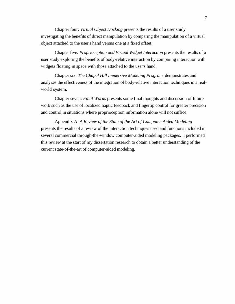
Chapter four: Virtual Object Docking presents the results of a user study
investigating the benefits of direct manipulation by comparing the manipulation of a virtual
object attached to the user's hand versus one at a fixed offset.
Chapter five: Proprioception and Virtual Widget Interaction presents the results of a
user study exploring the benefits of body-relative interaction by comparing interaction with
widgets floating in space with those attached to the user's hand.
Chapter six: The Chapel Hill Immersive Modeling Program demonstrates and
analyzes the effectiveness of the integration of body-relative interaction techniques in a real-
world system.
Chapter seven: Final Words presents some final thoughts and discussion of future
work such as the use of localized haptic feedback and fingertip control for greater precision
and control in situations where proprioception information alone will not suffice.
Appendix A: A Review of the State of the Art of Computer-Aided Modeling
presents the results of a review of the interaction techniques used and functions included in
several commercial through-the-window computer-aided modeling packages. I performed
this review at the start of my dissertation research to obtain a better understanding of the
current state-of-the-art of computer-aided modeling.

8
Chapter 2
Related Work
2.1 3-DoF and 6-DoF Object Manipulation Using 2D Input
Researchers have explored many alternatives in their search for effective techniques
for 3D interaction using 2D inputs. Much of the earliest work exploited the relationship
between 2D mouse movements and the projected image of the scene.
Gregory Nielson of Arizona State University and Dan Olsen of Brigham Young
University developed a technique they called the triad mouse [Nielson and Olsen, 1986] .
2D mouse motions were mapped into three-dimensions by comparing the screen-space
movement of the triad cursor with the projected image of its three axes (Figure 2.1).
Nielson and Olson similarly took advantage of the projections of object features in
performing object translations, rotations and scales. Users, for example, could translate
objects parallel to selected edges or rotate objects about the normal of a selected face.
(Yx,Yy)
(Zx,Zy)
(Xx,Xy)
(Dx,Dy)
(Yx,Yy)
(Zx,Zy)
(Xx,Xy)
(Dx,Dy)
A B
Figure 2.1: In Nielson's system 3D movement of the triad cursor depends
on the relationship between its screen-space movement (Dx,Dy) and the
projection of its axes. Case A would move the triad cursor in Z, case B
would move the triad cursor in X [Nielson and Olsen, 1986] .
9
Eric Bier of Xerox Parc has developed many innovative techniques for the precise
6-DoF manipulation of shapes relative to one another (scene composition) using only 2D
input devices and displays. In [Bier, 1986] he presents a type of 3D cursor he calls a
skitter. Movement of the skitter depends upon the projected image of objects in the scene.
The skitter moves along or perpendicular to the surface of objects and is used to place 3D
jacks in the scene. Jacks in turn are used during object transformations as anchors (such as
an axis of rotation) or to specify end conditions (such as the number of degrees to rotate).
Alternately they can be used as reference frames for moving the skitter in free space.
With [Bier, 1990] Bier continued his work in interactive scene composition by
extending his 2D Snap Dragging technique [Bier and Stone, 1986] to three dimensions.
Snap dragging combines a gravity function with alignment objects and interactive
transformations. The gravity function is used to snap the skitter to points, curves, and
surfaces in the scene. Alignment objects such as lines, planes, and spheres can be quickly
generated relative to existing features in the scene to allow for ruler-and-compass style
constructions in three dimensions. Finally, objects can be translated, rotated and scaled
interactively using the skitter, which continues to snap to objects during transformations.
Maarten van Emmerik of Delft University of Technology utilized a gesture-based
technique in [van Emmerik, 1990] for the direct manipulation of 3D objects with a
conventional 2D input device. As in the systems described by Nielson et al. and Bier, the
user interacts with a 3D perspective or parallel projection of the scene. In this case,
however, seven virtual control points are defined on the coordinate system associated with
each object or group. One point on the coordinate system is used for specifying
translation, the other six are used for specifying rotation and scaling. The user picks a
control point and drags it on the screen. The effect of the drag operation depends on the
selected control point, on the 2D movement of the cursor in screen space, and on the
orientation of the projected axes. If the user picks the center control point and drags along
the projection of the Z axis, for example, the object will move in the Z direction. This
scheme restricts transformations specified using the control points to single DoF changes.
In [Conner, et al., 1992] Conner, Snibbe et al. of Brown University formalized
the notion of using geometric objects as spatial referents which can be used to select
mappings of cursor motion to object behavior. They present the concept of 3D widgets,
encapsulated three-dimensional geometry and behavior which can be treated as any other
object in a 3D world (Figure 2.2). Widgets can be primarily geometric, such as the
dividing lines and frames which organize and partition an interface. Others, such as a
gestural rotation widget, may have no inherent geometry. Conner et al. claim that the

10
treatment of widgets as first-class objects results in higher bandwidth between interface and
application than exists in most traditional UI toolkit-based interfaces. Numerous examples
have been presented in the literature of ways to use explicit and implicit geometry to help
determine the mapping of 2D cursor movement in screen space to 3D object behaviors. See
for example the work on interactive shadows described by [Herndon, et al., 1992] or the
techniques for specifying 3D rotations using implied geometry such as the virtual sphere
[Chen, et al., 1988]x or the arcball x[Shoemake, 1992] .
Figure 2.2: Constrained geometric transformation using widgets [Conner,
et al., 1992] .
Instead of being explicitly encapsulated in three-dimensional geometry, object
behaviors can be implicitly encoded in a set of heuristics. Bukowski and Sequin of the
University of California at Berkeley, for example, define a set of pseudo-physical
behaviors they call object associations which determine the mapping between cursor motion
in screen space and the corresponding object motion in the 3D virtual world, see Figure 2.3
and [Bukowski and Sequin, 1995] . Objects are assigned behaviors such as on-horizontal
or on-vertical which are combined with association procedures such as pseudo-gravity,
anti-gravity, and on-wall to determine the object's resulting 3D motion. Bukowski and
Sequin also developed several implicit grouping mechanisms which helped to simplify
interaction in complex schemes.

11
Figure 2.3: Using object associations to map 2D cursor motions to three
dimensions [Bukowski and Sequin, 1995] .
2.2 Object Manipulation Using Higher-Dimensional Input
Realizing the limitations of using two-dimensional input devices for three-
dimensional manipulation, several researchers have explored the potential of higher
dimensional input devices.
Dan Veniola of Apple Computer, Inc. created a 3-DoF mouse he called the roller
mouse [Veniola, 1993] . In addition to the standard mouse ball encoder on the underside,
the roller mouse had two wheels on the front, one on either side of the single mouse
button. Moving the body of the mouse in the conventional way resulted in movements of a
3D cursor in the plane of the screen. Moving the wheels resulted in movements of the
cursor in a direction perpendicular to the screen. Users could thus control three degrees of
freedom simultaneously. To allow changes in both position and orientation to be specified
simultaneously with only a 3D input device, Veniola created an interaction technique he
called tail-dragging Objects moved using tail-dragging swing around like a rock on the end
of a string, trailing behind the direction of movement.
Balakrishnan of the University of Toronto along with Baudel, Kurtenbach and
Fitzmaurice of Alias|Wavefront have created a device they call the Rockin' Mouse
[Balakrishnan, et al., 1997] . Like Veniola's roller mouse, the Rockin' Mouse has a shape
that is similar to a conventional mouse. Instead of wheels mounted on the front of the
mouse, however, the Rockin' Mouse has a rounded bottom (Figure 2.4). This allow users

12
to control two additional degrees of freedom (for a total of four) by tilting the mouse left
and right and/or forward and backward while simultaneously moving the body like a
regular mouse. User studies conducted by the authors have shown that the Rockin' Mouse
has the potential of providing at least a 30% performance gain over the regular mouse on a
3D object-positioning task. The results also indicate that subjects were able to control all
three dimensions of an object's translation simultaneously.
Figure 2.4: The Rockin' Mouse [Balakrishnan, et al., 1997] .
Colin Ware of the University of New Brunswick has investigated the use of 6-DoF
input devices he calls bats, hand-held input devices using magnetic trackers [Ware and
Jessome, 1988] . Ware found that subjects can perform coarse positioning tasks faster
when they simultaneously control all six degrees of freedom of an object's position and
orientation than they can when they control position and orientation separately. He also
found, however, that precise 3D positioning is difficult to achieve when the arm or hand is
unsupported. Rotations of the bat produce inadvertent translations and vice versa.
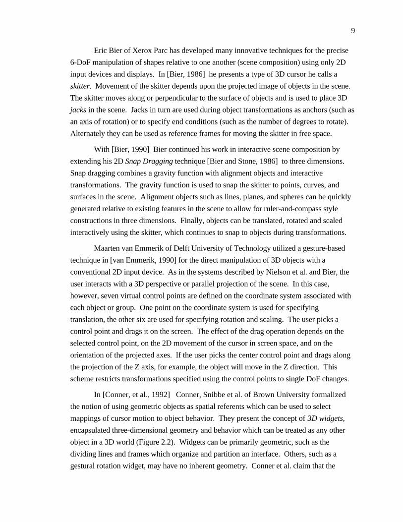
University of Toronto researchers Zhai, Milgram, and Buxton have performed a
series of evaluations of manipulation techniques which use 6-DoF input devices.
[Zhai and Milgram, 1993] presents a three-dimensional conceptual space for
classifying multi-degree-of-freedom manipulation schemes (see Figure 2.5). The X axis of
the discrete space represents mode of sensing. The two extremes for this axis are: isotonic
(muscular contraction in the absence of significant resistance) and isometric (muscular
contraction against resistance) sensing. The region between the extremes represents
spring-loaded elastic sensing. An example of an isotonic controller would be the
magnetically tracked glove used in many virtual environment systems. The Spaceball TM
input device is an example of an isometric input device.
13
Figure 2.5: Zhai et al.'s framework for the study of multi-degree-of-
freedom manipulation schemes [Zhai and Milgram, 1993] .
The Y axis of the model represents different mapping relationships between the
user's limb and the resulting movement of an object. Near the origin of this axis is pure
position control in which the output of the user's limb is mapped to object position or
orientation by a pure gain. At the outer extreme of the axis is rate control in which output
of the user's limb is mapped to object velocity using a first order time integration.
The final axis of their model is the degree of integration, where the origin represents
a fully integrated (6 DoF) control and the outer extreme represents six separate 1 DoF
controllers. Between the extremes would lie two 3 DoF controllers, one for rotation and
one for translations.
Zhai et al. compared isotonic-position, isotonic-rate, isometric-rate, and isometric-
position control approaches in an experimental 6 DoF docking task. They observed a
strong interaction between sensing mode and mapping; performance was better only when
isometric sensing was combined with rate control or when isotonic sensing was combined
with position control. They noted that comparisons of interface design based simply on
comparing sensing mode or mapping function would be misleading.
[Zhai, et al., 1996] discusses the advantages of using the fine, smaller muscle
groups and joints in the fingers for the 6 DoF manipulation of objects. They found that in a
3D object docking experiment, users' task completion times were significantly shorter with
devices that utilized the fingers.
Balakrishnan and MacKenzie from the University of Toronto and the University of
Guelph respectively, however, found that the finger(s) do not necessarily perform better
14
than the other segments of the upper limb in the context of a reciprocal point-select task
[Balakrishnan and MacKenzie, 1997] . The bandwidth of the unsupported index finger is
actually less (3.0 bits/second) than the wrist and forearm which have bandwidths of
approximately 4.1 bits/second. They also found that the thumb and index finger working
together in a pinch grip have an information processing rate of about 4.5 bits/second. They
concur with Zhai et al., however, that well designed pointing devices which rely on all
parts of the human upper limb working in synergy can indeed outperform devices which
depend on a particular limb segment for their entire operation.
2.3 Two-handed Interaction
2.3.1 Example Techniques
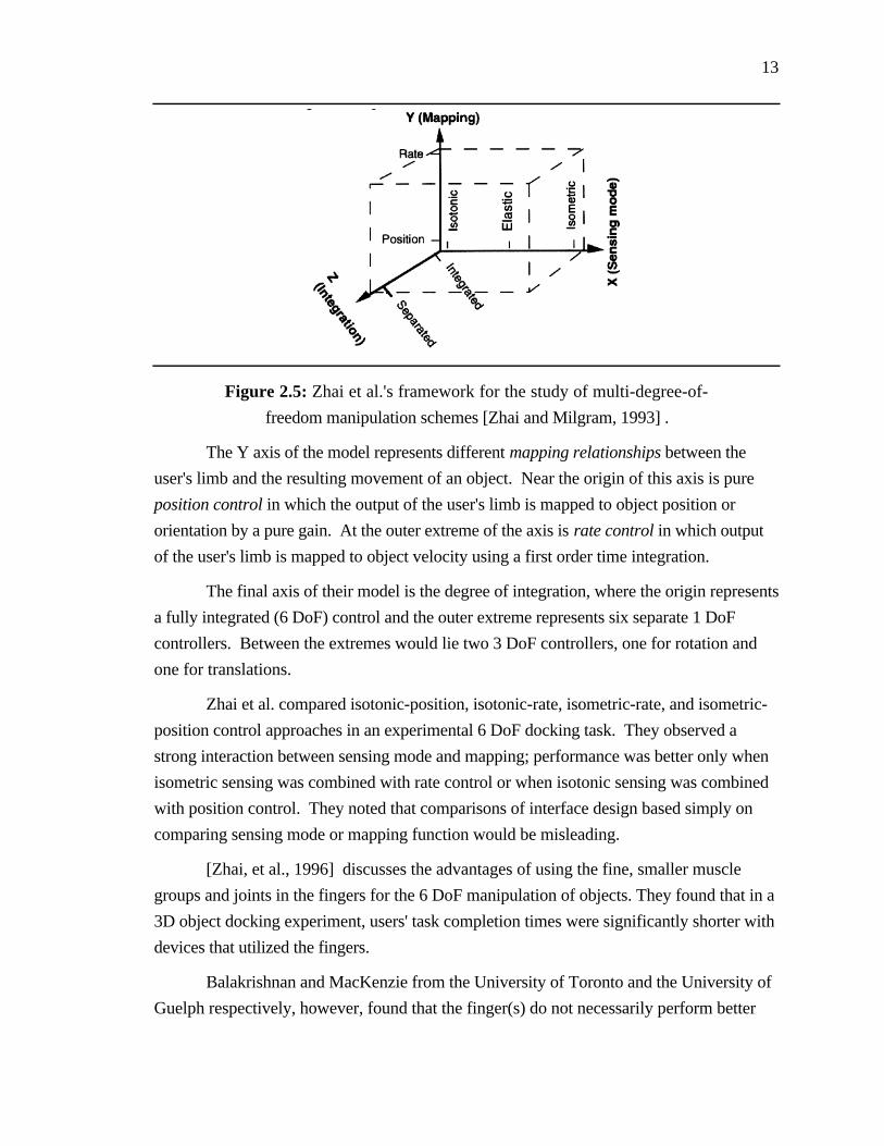
Recently, many researchers have explored the benefits of using two-handed
interaction techniques in human-computer interfaces. The work of Bier et al. on the
Toolglass and Magic Lenses interface, for example, demonstrated that the use of two hands
exploits user's everyday skills and reduces steps, cursor motion and errors during
interaction [Bier, et al., 1993] . In the Toolglass and Magic Lens system, one hand
positions a movable see-through interface, a cursor controlled by the other hand points
through to underlying objects (Figure 2.6).
Figure 2.6: Layers in a toolglass system [Bier, et al., 1994] .

15
Figure 2.7: Using toolglasses, two-hands, and transparency in T3
[Kurtenbach, et al., 1997] .
Toolglasses and two-handed input also play an important role in recent research by
Kurtenbach, Fitzmaurice, Baudel, and Buxton of Alias|Wavefront [Kurtenbach, et al.,
1997] . Their goal in developing a system they call T3 (for toolglasses, two-hands, and
transparency) was to maximize the amount of screen used for application data and to
minimize the amount the UI diverts visual attention from the application data. Users
interact with the workspace using two tablet-based puck devices which sense single-axis
rotation in addition to x and y position (Figure 2.7). Using his non-dominant hand the user
moves semi-transparent toolglasses. He interacts with these toolglasses using cursors
controlled by his dominant hand. Marking menus (Figure 2.8 and [Kurtenbach and
Buxton, 1993] ) are used to allow the user to select quickly among the set of toolglass
sheets.

16
Figure 2.8: Marking Menus interaction. Novice users can perform
selections by popping-up a radial (or pie) menu. Expert users can make
selections more quickly by making a straight mark in the direction of the
desired menu item without popping-up the menu [Kurtenbach and Buxton,
1993] .
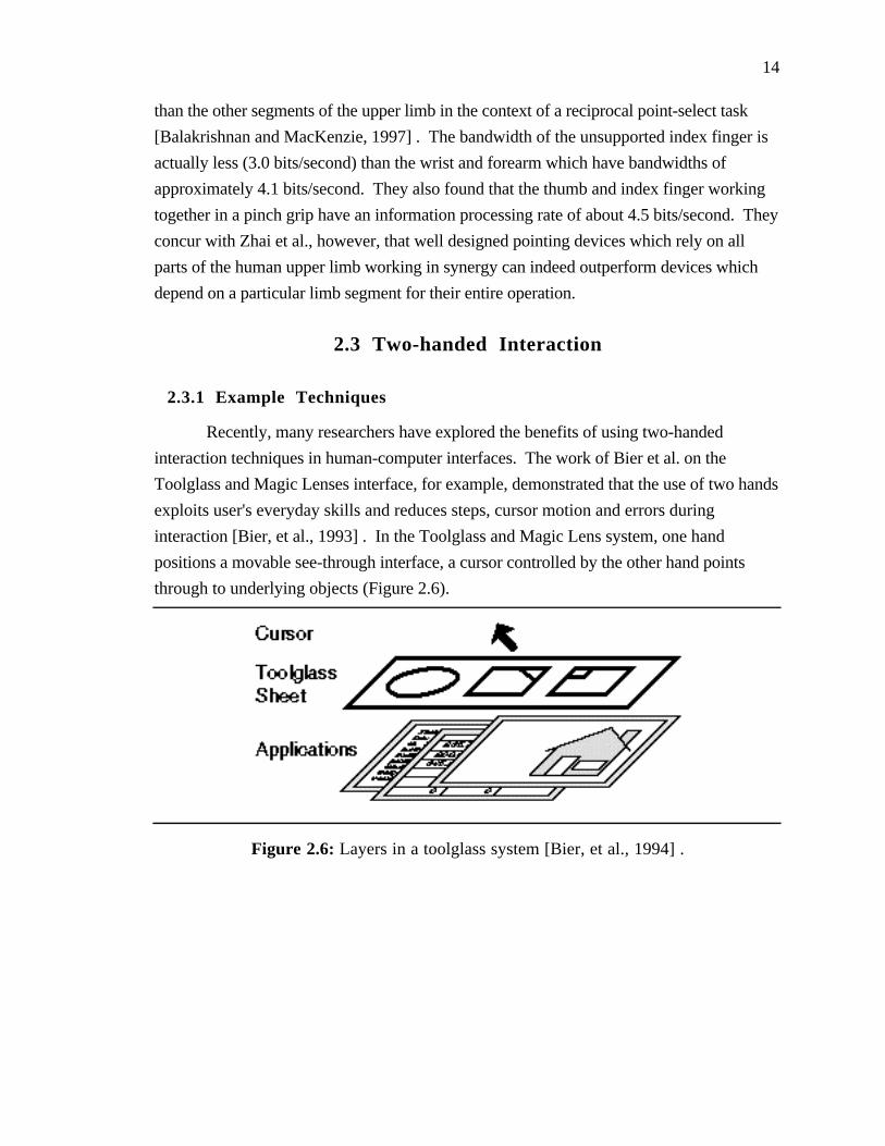
Goble, Hinckley, et al. at the University of Virginia have demonstrated the
advantages of using two hands in conjunction with props, (real-world hand-held tools) in
their Netra system, an interactive tool for neurosurgical planning [Hinkley, et al., 1994;
Goble, et al., 1995] . In the Netra system neurosurgeons control the current viewpoint and
cross-section plane used to display medical imaging data on a conventional workstation by
manipulating real-world props held in their two hands (Figure 2.9). A small doll head held
in one hand controls the viewpoint and scale of the displayed information. A small plate
held in the other hand controls the current cross-sectioning plane. The use of physical
props takes advantage of a human's highly developed ability to manipulate real-world
objects and provides visual and kinesthetic feedback that reminds the user of the prop's
use. Hinkley's work supports previous work [Badler, et al., 1986] which showed that
interaction relative to a real (as opposed to imaginary) object made a previously difficult
and/or tedious task, such as the specification of a camera viewpoint relative to a virtual
object, quite simple.
17
Figure 2.9: Using two hands and props in Netra [Hinkley, et al., 1994] .
Related work at Alias|Wavefront and the University of Toronto by George
Fitzmaurice and Bill Buxton further demonstrates the advantages of interacting with
computer applications using dedicated physical interface widgets. [Fitzmaurice, et al.,
1995] describes an innovative system called Bricks which allows direct control of
electronic or virtual objects through physical handles for control called bricks. Users, for
example, move and rotate a virtual object by manipulating a physical brick placed on top of
it (see Figure 2.10a). With multiple bricks user can perform more complex operations such
as simultaneously positioning and sizing a virtual object (using a brick held in each hand)
or specifying multiple control points on a spline curve (see Figure 2.10b). In [Fitzmaurice
and Buxton, 1997] they present the results of experimental evaluations of their graspable
user interface. They show that the space-multiplexed graspable interface (in which multiple
physical objects are used to control several virtual objects) outperforms a conventional
time-multiplexed interface (in which a single input device such as a mouse controls
different functions at different points in time) for a variety of reasons, including the
persistence of attachment between the physical device and the logical controller.

18
Figure 2.10: Object manipulation and spline editing using Fitzmaurice et
al's graspable user interface [Fitzmaurice, et al., 1995] .
Robert Zeleznik, and Andrew Forsberg of Brown University along with Paul
Strauss of Silicon Graphics Computer Systems have developed several techniques for
object transformation, geometric editing, and viewpoint control which use two hands to
control two independent cursors [Zeleznik, et al., 1997] . They report that the best
mappings of application DoFs to cursor DoFs are those which seem to have the strongest
physical analogs. They also state that given appropriate mappings, two-handed interaction
allows users to perform complex 3D operations more quickly and efficiently than with
single cursor techniques.
Cutler, Fröhlich and Hanrahan of Stanford University have built a system which
allows users to manipulate virtual models using both hands on a tabletop VR device called
the Responsive Workbench (Figure 2.11) [Cutler, et al., 1997] . They present a
framework of three basic building blocks: manipulators which encapsulate devices, tools
which define the interactions, and toolboxes which allow for transitions between different
tools. One of their most interesting findings was that users often performed two-handed
manipulations by combining otherwise independent one-handed tools in a synergistic way.

19
Figure 2.11: The Responsive Workbench [Stanford, 1997] .
Several interactive design systems (3-Draw, U.Va's WIM, Polyshop, Gobetti's
Animation system, and THRED ) described in Section 2.5 below also use two hands for
object manipulation and environment interaction. In all of these systems, researchers report
that users quickly adapt to the two-handed mode of interaction, finding it intuitive, easy to
use, and often more effective than one-handed interaction.
2.3.2 Theoretical and Experimental Results
Yves Guiard (of the Centre National de la Recherche Scientifique in Marseille,
France) presents a theoretical framework which can be used in the study of two-handed
interaction [Guiard, 1987] . Guiard proposes that human bimanual behavior can be
modeled as a kinematic chain, a serial linkage of abstract motors. Based on this model he
presents three high-order principles governing the asymmetry of human bimanual gestures.
• The actions of a person's dominant hand are typically performed relative to acoordinate frame defined by his non-dominant hand.
• The dominant hand works at a finer spatial-temporal scale than the non-dominant hand.
20
• The actions of the dominant hand typically start after those of the non-dominanthand.
Effective two-handed interaction techniques must take these results into
consideration, with the non-dominant hand setting the context in which the dominant hand
interacts.
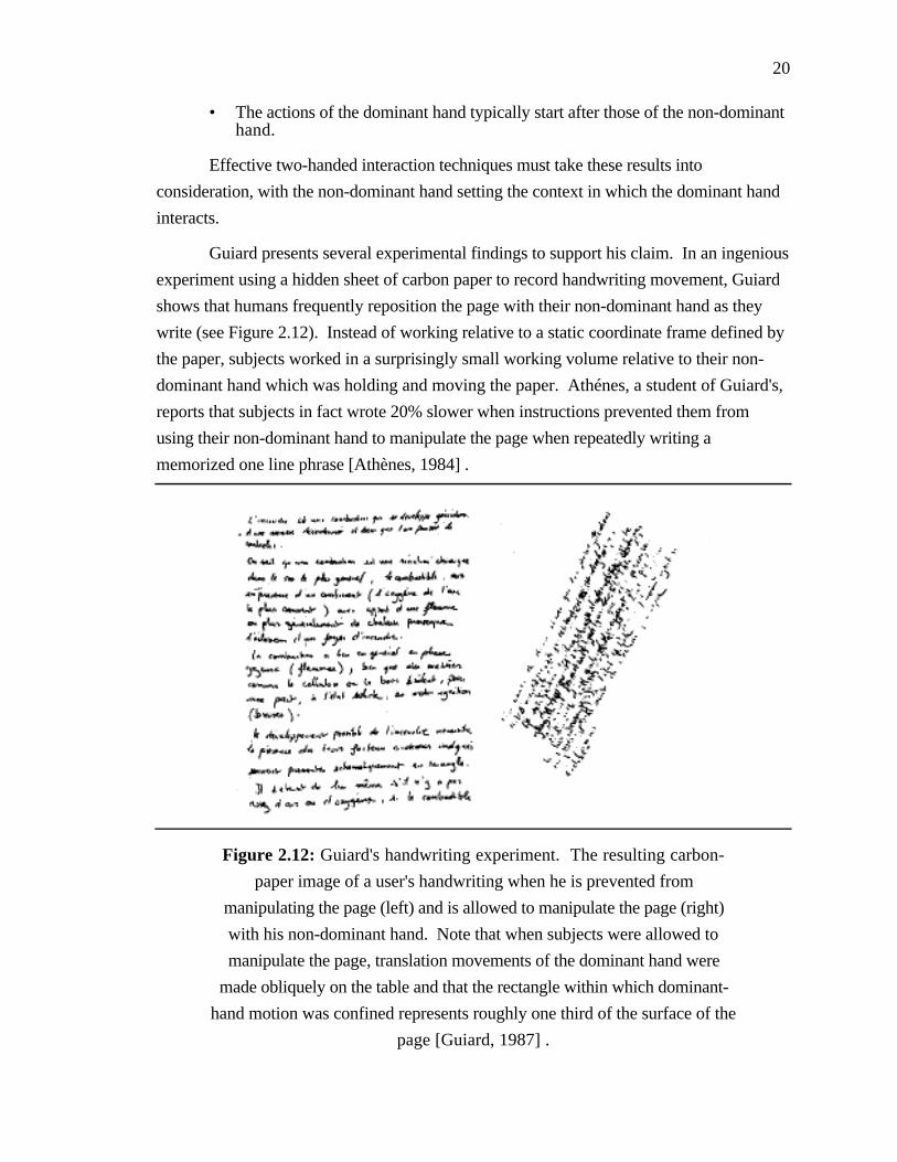
Guiard presents several experimental findings to support his claim. In an ingenious
experiment using a hidden sheet of carbon paper to record handwriting movement, Guiard
shows that humans frequently reposition the page with their non-dominant hand as they
write (see Figure 2.12). Instead of working relative to a static coordinate frame defined by
the paper, subjects worked in a surprisingly small working volume relative to their non-
dominant hand which was holding and moving the paper. Athénes, a student of Guiard's,
reports that subjects in fact wrote 20% slower when instructions prevented them from
using their non-dominant hand to manipulate the page when repeatedly writing a
memorized one line phrase [Athènes, 1984] .
Figure 2.12: Guiard's handwriting experiment. The resulting carbon-
paper image of a user's handwriting when he is prevented from
manipulating the page (left) and is allowed to manipulate the page (right)
with his non-dominant hand. Note that when subjects were allowed to
manipulate the page, translation movements of the dominant hand were
made obliquely on the table and that the rectangle within which dominant-
hand motion was confined represents roughly one third of the surface of the
page [Guiard, 1987] .
21
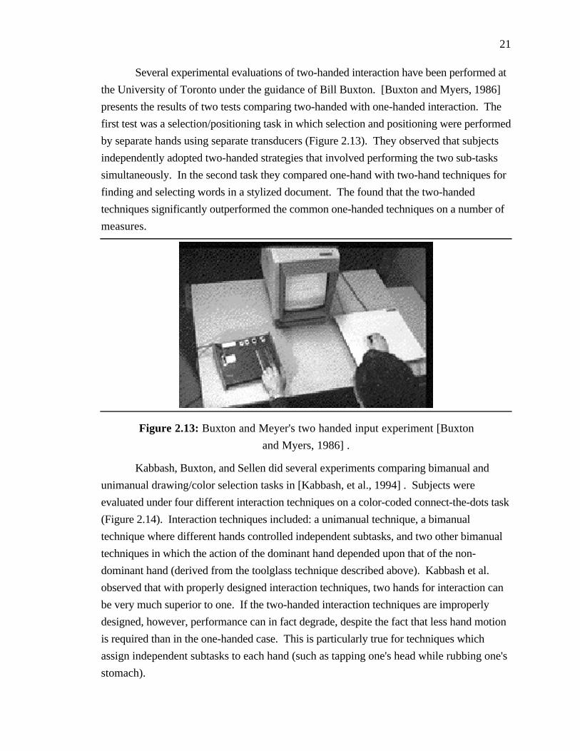
Several experimental evaluations of two-handed interaction have been performed at
the University of Toronto under the guidance of Bill Buxton. [Buxton and Myers, 1986]
presents the results of two tests comparing two-handed with one-handed interaction. The
first test was a selection/positioning task in which selection and positioning were performed
by separate hands using separate transducers (Figure 2.13). They observed that subjects
independently adopted two-handed strategies that involved performing the two sub-tasks
simultaneously. In the second task they compared one-hand with two-hand techniques for
finding and selecting words in a stylized document. The found that the two-handed
techniques significantly outperformed the common one-handed techniques on a number of
measures.
Figure 2.13: Buxton and Meyer's two handed input experiment [Buxton
and Myers, 1986] .
Kabbash, Buxton, and Sellen did several experiments comparing bimanual and
unimanual drawing/color selection tasks in [Kabbash, et al., 1994] . Subjects were
evaluated under four different interaction techniques on a color-coded connect-the-dots task
(Figure 2.14). Interaction techniques included: a unimanual technique, a bimanual
technique where different hands controlled independent subtasks, and two other bimanual
techniques in which the action of the dominant hand depended upon that of the non-
dominant hand (derived from the toolglass technique described above). Kabbash et al.
observed that with properly designed interaction techniques, two hands for interaction can
be very much superior to one. If the two-handed interaction techniques are improperly
designed, however, performance can in fact degrade, despite the fact that less hand motion
is required than in the one-handed case. This is particularly true for techniques which
assign independent subtasks to each hand (such as tapping one's head while rubbing one's
stomach).

22
Figure 2.14: Kabbash et al's two-hand connect the dots experiment
[Kabbash, et al., 1994] .
Leganchuk, Zhai, and Buxton compared two bimanual techniques with a
conventional one-handed technique for sweeping out a bounding box [Leganchuk, et al.,
1997] . The bimanual techniques resulted in a significantly better performance than the
one-handed techniques. Interestingly, the differences in performance cannot be wholly
accounted for by time-motion efficiency. They postulate that the representation of the task
as a bimanual task reduces cognitive load.
2.4 Manipulating Objects Using Gesture and Voice
In [Krueger, 1991; Krueger, 1993] Myron Krueger, president of Artificial Reality
Corporation, describes his VIDEOTOUCH, VIDEOPLACE, and VIDEODESK
applications. Championing a "come as you are" interface, Krueger prefers the use of
external devices, such as video cameras, instead of hand-held or body-mounted devices to
track the user and his body parts. Krueger uses image processing techniques to extract
image features, such as the position and orientation of the user's hands and fingers, and
uses them in a set of intuitive gestures for the manipulation of virtual objects. Users, for
example, can swat at a virtual ball using a whole-hand gesture or can use their fingertips to
manipulate the control points of a spline curve (Figure 2.15).

23
Figure 2.15: VIDEODESK two-handed interaction [Krueger, 1991] .
Kurtenbach and Buxton of the University of Toronto developed an interactive
system for 2D graphical editing using contiguous gestures they called GEdit [Kurtenbach
and Buxton, 1991] . They defined a set of simple gestures, such as striking a mark
through an object to delete it or drawing a lasso around a group of objects to select and
move them (see Figure 2.16), which were both intuitive and easy to implement using a
mouse or a stylus.
Zeleznik of Brown University has extended the concept of using of 2D gestures for
graphical editing to include techniques for the creation of 3D objects in his SKETCH
system, described in Section 2.5 below [Zeleznik, et al., 1996] .
Figure 2.16: Using a gesture to move a group in GEdit [Kurtenbach and
Buxton, 1991] .
24
Interesting results from several researchers have shown that the combination of
speech input with gestures results in much richer forms of interaction than is possible with
either modality alone.
Some of the earliest work was performed by Richard Bolt at MIT's Media Lab. In
his innovative Put-that-there system [Bolt, 1980] users could manipulate objects on a large
screen using a combination of speech and gestures. Gestures were used to select objects
and to specify destinations, and voice input was used to specify actions. Not only did the
combination of speech and gestures increase the power of the resulting interactions it also
simplified the respective components. Through pronomialization users could replace
complex commands such as "Move the blue triangle to the right of the green square" to
simple and intuitive phrases such as "Put that there". The pronoun and the desired
destination were disambiguated using the pointing gesture. Bolt and other researchers at
the Media Lab have extended these techniques to include two-handed interaction and eye
tracking [Bolt and Herranz, 1992; Thorison, et al., 1992] .
A classic study exploring the use of speech input and/or gestures for the 3D
translation, rotation and scaling of objects was performed by Alexander Hauptmann at
Carnegie-Mellon University [Hauptmann, 1989] . Acknowledging the challenges of both
speech and gesture recognition, Hauptmann substituted a human in an adjacent room for
the recognition devices. Hauptmann's experiment revealed that users strongly preferred
using simultaneous speech and gestures and that they intuitively used multiple hands and
multiple fingers in all three dimensions. Hauptmann also reported that there was a
surprising uniformity and simplicity in the gestures and speech used for the manipulation
tasks. Though given no prior instructions or limits on what they could say, subjects only
used on average 5.8 words per trial and had a surprisingly compact lexicon of 141 different
useful words.
Weimer and Ganapathy of AT&T Bell Laboratories used speech with single-hand
gestural input to perform a set of object placement and solid-modeling tasks [Weimer and
Ganapathy, 1989] . They reported that their system, which was initially implemented
without speech input, was dramatically improved by the addition of speech. Gesturing was
limited to a small vocabulary that consisted of three different gestures using only the
thumb.
2.5 Systems for Interactive Design
Several systems have moved beyond the limitations of two-dimensional input and
output in the interactive design of virtual objects. One can categorize these systems

25
according to the type of input devices used (number and degrees-of freedom of each), and
the type of outputs used:
Input:
• Single 3-DoF input (3D position only)
• Single 6-DoF input (3D position and orientation)
• Two 6-DoF inputs (one for each hand)
Output:
• Conventional workstation display
• Static stereo display (workstation monitor with stereo output)
• Head-tracked kinetic display (non-stereo display with head tracking)
• Head-tracked stereo display (Fish Tank VR)
• Immersive head-mounted display
Table 1 tabulates the inputs and outputs used in the systems discussed below.
Table 2.1: Interactive design systems input/output comparison. Systems are specified by
author/institution/system-name (if applicable).
INPUT
OUTPUT 3-DoF 6-DoF 2 X 6-DoF
ConventionalDisplay
Sachs/MIT/3-Draw
Shaw/Alberta/THRED
Zeleznik/Brown/Sketch (2x2-DoF)
Stereo Display Schmandt/MIT/
Head Tracking Liang/Alberta/JDCAD
Head-tracked Stereo Deering/Sun/HoloSketchGobetti/CRS4/
Immersive Head-mounted Display
Clark/Utah/ Butterworth/UNC/3DM
Bowman/Ga.Tech/CDS
Stoakley/U.Va./WIM
Mapes/IST/Polyshop
Mine/UNC/CHIMP
2.5.1 Working Through-the-window
Christopher Schmandt of the Architecture Machine Group at the Massachusetts
Institute of Technology (MIT) used a video display combined with PLZT shutter glasses
and a half-silvered mirror to create a stereo image that was registered with a physical
workspace (Figure 2.17) [Schmandt, 1983] . Users could reach in and directly interact
with virtual objects in the workspace using a 6-DoF magic wand. The wand used an early
Polhemus tracking system and included a button for user input. Though users were
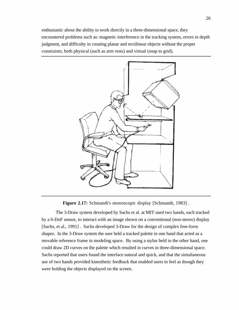
26
enthusiastic about the ability to work directly in a three-dimensional space, they
encountered problems such as: magnetic interference in the tracking system, errors in depth
judgment, and difficulty in creating planar and rectilinear objects without the proper
constraints, both physical (such as arm rests) and virtual (snap to grid).
Figure 2.17: Schmandt's stereoscopic display [Schmandt, 1983] .
The 3-Draw system developed by Sachs et al. at MIT used two hands, each tracked
by a 6-DoF sensor, to interact with an image shown on a conventional (non-stereo) display
[Sachs, et al., 1991] . Sachs developed 3-Draw for the design of complex free-form
shapes. In the 3-Draw system the user held a tracked palette in one hand that acted as a
movable reference frame in modeling space. By using a stylus held in the other hand, one
could draw 2D curves on the palette which resulted in curves in three-dimensional space.
Sachs reported that users found the interface natural and quick, and that the simultaneous
use of two hands provided kinesthetic feedback that enabled users to feel as though they
were holding the objects displayed on the screen.
27
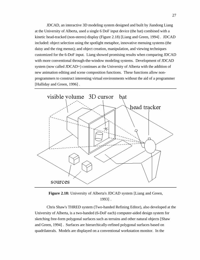
JDCAD, an interactive 3D modeling system designed and built by Jiandong Liang
at the University of Alberta, used a single 6 DoF input device (the bat) combined with a
kinetic head-tracked (non-stereo) display (Figure 2.18) [Liang and Green, 1994] . JDCAD
included: object selection using the spotlight metaphor, innovative menuing systems (the
daisy and the ring menus); and object creation, manipulation, and viewing techniques
customized for the 6-DoF input. Liang showed promising results when comparing JDCAD
with more conventional through-the-window modeling systems. Development of JDCAD
system (now called JDCAD+) continues at the University of Alberta with the addition of
new animation editing and scene composition functions. These functions allow non-
programmers to construct interesting virtual environments without the aid of a programmer
[Halliday and Green, 1996] .
Figure 2.18: University of Alberta's JDCAD system [Liang and Green,
1993] .
Chris Shaw's THRED system (Two-handed Refining Editor), also developed at the
University of Alberta, is a two-handed (6-DoF each) computer-aided design system for
sketching free-form polygonal surfaces such as terrains and other natural objects [Shaw
and Green, 1994] . Surfaces are hierarchically-refined polygonal surfaces based on
quadrilaterals. Models are displayed on a conventional workstation monitor. In the

28
THRED system each hand has a distinct role; the less dominant hand sets context such as
the axis of interaction while the dominant hand is responsible for actions such as picking
and manipulation.
Michael Deering at Sun Microsystems Computer Corporation has created the
HoloSketch system, a VR based sketching system that extends the 2D sketch-draw
paradigm to 3D [Deering, 1996] . A head-tracked stereo system that uses a 6-DoF wand,
the HoloSketch system supports several types of 3D drawing primitives such as rectangular
solids, spheres, cylinders, cones, free-form tubes, and many more. Users control
HoloSketch using a 3D multi-level fade up circular menu which, when invoked, fades up
centered around and slightly behind the current location of the wand. The fade-up menu is
used to select the current drawing primitive or to perform one-shot actions such as cut or
paste. Deering reports that trials with non-computer scientists (the intended users) have
shown that significant productivity gains are possible over conventional 2D interface
technology.
Gobbetti and Balaguer of the Center for Advanced Studies, Research and
Development in Sardinia have created an integrated environment for the rapid prototyping
of 3D virtual worlds [Gobbetti and Balaguer, 1995] . Their system is built on top of the
VB2 system, a graphics architecture based on objects and constraints developed by the
authors at the Swiss Federal Institute of Technology, Lausanne [Gobbetti and Balaguer,
1993] . The system uses two hands for input (using a mouse and a Spaceball), and a head-
tracked stereo display (using LCD shutter glasses) for output. It also uses multi-way
constraints to simplify the development of 3D widgets and the specification of compound
widgets and interaction techniques.
Zeleznik, Herndon, and Hughes of Brown University have developed an
innovative system using a conventional 2 DoF mouse for the rapid conceptualization and
editing of approximate 3D scenes (as contrasted with precise 3D models generated in
conventional computer modeling systems) called SKETCH [Zeleznik, et al., 1996] .
SKETCH utilizes a gestural interface based on simplified line drawings of primitives that
allows all operations to be specified within the 3D world. To create a cube for example,
users simply draw three perpendicular lines which intersect at a point. The lengths of the
lines determine the dimensions of the cube. To create a different shape the user simply
makes a different gesture (two parallel lines for a cylinder, for example) instead of selecting
a different tool from a tool palette. SKETCH also uses several heuristics to determine the
relative 3D location of objects based on the sequence of input strokes. T junctions, for
example, are used to infer the relative placement of objects, such as a leg intersecting a table

29
top (see Figure 2.19). Zeleznik has recently extended the SKETCH interface to two-hands
as described in [Zeleznik, et al., 1997] .
Figure 2.19: Using T junctions to infer object placement in SKETCH
[Zeleznik, et al., 1996] .
A current trend not specific to the field of interactive design, but important to the
development of interactive through-the-window systems in general, is the use of horizontal
or near horizontal display surfaces which project stereoscopic images.
Poston and Serra at the Centre for Information-Enhanced Medicine at the University
of Singapore, for example, use a tilted mirrored display system [Poston and Serra, 1994;
Poston and Serra, 1996] similar to that employed by Schmandt. Users can reach into a
virtual space and interact with virtual objects using a physical tool handle which can have
different virtual end effectors attached to it. Though designed for medical applications the
authors foresee potential applications in many areas including computer-aided design.
The Responsive Workbench, originally developed at GMD (the German National
Research Center for Information Technology ) [Krueger and Fröhlich, 1994] with
continued work at Stanford University [Stanford, 1997] , uses a projector-and-mirrors
system to project a high-resolution, stereoscopic image onto a horizontally-mounted
projection screen (Figure 2.11). This system makes it possible for users to interact with
applications using an intuitive tabletop metaphor. Similar systems include the Immersive
Workbench by Silicon Graphics and Fakespace [Fakespace, 1997] , the ImmersaDesk
from the Electronic Visualization Laboratory at the University of Illinois at Chicago [EVL,
1997] , and the NanoWorkbench at the University of North Carolina [UNC, 1997] which
also incorporates a PhantomTM force feedback arm (Figure 2.20).

30
Figure 2.20: UNC's nanoWorkbench [UNC, 1997] .
2.5.2 Working Immersed
Back in the mid 70's at the University of Utah, Jim Clark built one of the earliest
interactive design systems that used an immersive head-mounted display. Clark developed
his pioneering system for use in the interactive design of free-form surfaces in three-
dimensions [Clark, 1976] . Clark's system used a mechanically tracked head-mounted
display designed by Ivan Sutherland and a 3 DoF wand that computed positions by
measuring the length of three monofilament lines attached to the ceiling. Primarily limited
by the state of available technology (in particular the tracking technology and graphics
system), the system addressed many of the issues that face developers of interactive design
systems today.
3DM (Three-dimensional modeler) is an interactive design system created at the
University of North Carolina in the early 90's [Butterworth, et al., 1992] . Using a stereo
head-mounted display and a single 6 DoF bat, 3DM allows users to interactively create
geometric objects from within a virtual environment. 3DM includes several grid and snap
functions, but it lacks many of the other aids and constraints that we since have found
necessary for accomplishing precise work.
The University of Virginia's Worlds-in-Miniature (WIM) system ([Stoakley, et al.,
1995] ) is an innovative system that uses a hand-held miniature representation of the virtual

31
environment (the WIM) for object manipulation and viewer navigation (Figure 2.21). The
system uses two 6-DoF inputs, one attached to a physical clipboard held in one hand, and
one attached to a 6-DoF bat held in the other hand. Users manipulate objects in the virtual
world by manipulating objects in the virtual hand-held miniature which is attached to the
clipboard. Moving the copy of an object in the WIM results in the corresponding
movement of the full-sized original. Moving a representation of the user in the WIM
effects a change in viewpoint. The authors report that users quickly adapted to the WIM
interface finding it intuitive and easy to use.
Figure 2.21: University of Virginia's World-In-Miniature [Stoakley, et
al., 1995] .
The Conceptual Design Space system is an immersive head-mounted display
system for interactive architectural design that was developed at the Graphics, Visualization
and Usability Center at the Georgia Institute of Technology [Bowman and Hodges, 1995] .
Using a single 6-DoF input, users interact with objects and widgets using a ray-casting
metaphor. The developers of the CDS system have adapted many of their interface
elements and tools directly from 2D interfaces. To help create a highly usable immersive
architectural design tool, the developers of CDS have worked closely with actual architects
and members of the College of Architecture at Georgia Tech.
In the Polyshop system, developed at University of Central Florida's Institute for
Simulation and Training, two hands are used to scale, rotate, and translate objects within
the virtual world [Mapes and Moshell, 1995] . Users select specific modes of operations

32
using two ChordGloves, which provide a discrete form of gesture recognition.
ChordGloves have separate electrical contacts at the end of each finger and on each palm.
Different gestures consist of different chord patterns of electrical contacts. Mapes and
colleagues continue this work at MultiGen Inc. with the development of the SmartScene, a
virtual-world scene-building application [MultiGen, 1997] . SmartScene includes many
powerful and intuitive techniques such as hand-held palettes, two-handed flying, dynamic
scaling of the world (also using two-hands), and ModelTime Behaviors (predefined
snapping, popping, and stretching behaviors).

33
Chapter 3
Body-RelativeInteraction Techniques
This chapter is intended to give the reader a better understanding of the concept of
body-relative interaction. First I present automatic scaling as a means of bringing objects
instantly in reach so that users can manipulate them using proprioceptive cues. Then I
present detailed examples of three forms of body-relative interaction: direct manipulation,
physical mnemonics, and gestural actions.
3.1 Working Within Arm's Reach
I have found that interacting within a user's natural working volume (i.e. within
arm's reach) gives the user a greater sense of the position and orientation of the objects
being manipulated than interacting with remote objects outside of this range (e.g. using
laser beams). Interacting within a user's natural working volume has these advantages:
• takes advantage of proprioceptive information
• provides a more direct mapping between hand motion and object motion
• yields stronger stereopsis and head-motion parallax cues
• provides finer angular precision of motion
Often the target of manipulation lies outside of the user's reach. Though he can
move to reach it, constantly switching between object interaction and movement control
breaks the natural rhythm of the operation and adds significant cognitive overhead. An
automatic scaling mechanism is a convenient way to allow the user to interact instantly with
objects falling at any distance as though they were within arm's reach.

34
1) Select 2) Grab
3) Manipulate 4) Release
Figure 3.1: Automatic scaling of the world when the user grabs and
releases an object.
Selected objects that lie outside of the reach of the user are brought instantly into
reach by automatically scaling down the world about the user. For example, if the user's
arm is extended 0.5 meters, the application brings a selected object that is 5 meters away to
the user's hand by scaling down the world by a factor of 10 (see Figure 3.1)3. Scaling
takes place at the start of each manipulation and is reset when the user is done (when the
user grabs and then releases an object, for example). The scale factor depends on the
currently selected object; if the user selects an object that is 15 meters away instead of 5
meters, the application scales down the world by a factor of 30.
The scaling factor used to scale down the world (or conversely, scale up the user) is
equal to the ratio of the distance of the object being manipulated to the distance of the user's
hand:
3More precisely the object will move to a point on the surface of a sphere whose radius is equal to the
user's current arm extension. The object will move to the user's hand only if his hand lies along the vector fromthe scaling center (the user's head) to the object. This is the case when the user's hand visually occludes theobject.

35
head_ object
projection of head_ hand onto head_ object
where head_object is the vector from the user's head (defined to be the midpoint
between the user's eyes) to the object, and head_hand is the vector from the user's head to
his hand (Figure 3.2).
head_hand
head_object
Figure 3.2: Vectors used in determining automatic scaling factor.
If the center of the scaling operation is chosen to be the point midway between the
user's eyes, the user will, usually, be unaware that scaling has taken place, due to the
ambiguity of perspective projections. This is particularly true if the inter-pupilary distance
used to compute stereo images is also adjusted by the same scaling factor. This saves the
user's having to reconverge the eyes. The most noticeable change is an apparent change in
the size of the user's hand (which was not scaled). This can be offset by using non-
realistic hand representations such as 3D crosshairs whose size is harder for the user to
estimate visually.
A more implicit effect of the scaled-down world is the more dramatic effects of head
movements; a small movement left-to-right may enable the user to see a big object such as a
house from different sides, as though it were a dollhouse. While, in general, this is
desirable, in some cases head motion results in distracting movement of small, nearby
objects.

36
3.2 Sample Interaction Techniques
3.2.1 Direct Manipulation
3.2.1.1 Scaled-World Grab for Manipulation
An example of the power of automatic scaling is scaled-world grab. In scaled-
world grab, the world is automatically scaled down about the user's head every time he
grabs an object and scaled back up when he releases it. With the object at the user's hand
he can exploit proprioception, stereopsis, and head-motion parallax as he grabs an object
and moves it.
Scaled-world grab is a powerful technique with an important property: it minimizes
user work for a given result. With scaled-world grab the user can bring the most remote
object in the scene to his side in a single operation; he doesn't have to fly (or worse, walk)
to reach it or repeatedly grab, drop, and regrab the object to reel it in. Furthermore, since
the scale factor is automatically set, the user can manipulate near and far objects with equal
ease. Scaled-world grab makes excellent use of a user's proprioceptive information for
radial object movement, too: if the user halves his arm extension, the distance to the object
will be halved. Movement of an object is easy for the user to control, predict and
understand. Scaled-world grab is a surprising yet intuitive technique. In our informal user
trials we have observed that users are often surprised to learn that scaling has taken place,
but they have no problem using the technique.
Related Work
The principles on which scaled-world grab is based have their foundations in the
lessons I learned while exploring other forms of remote object manipulation.
Originally, for example, I tried the remote manipulation of objects via laser beams
[Mine, 1996; Mine, 1997] (and later spotlights, following [Liang and Green, 1994] ). I
found, however, that even though these beams extend a user's reach, they are effective
only for translations perpendicular to the beam direction and rotations about the beam axis.
While it is easy to move an object about in an arc, translations in the beam direction and
arbitrary rotations are much more difficult, requiring the user to repeatedly grab, move,
drop, and re-grab the object.
A very effective way to specify arbitrary rotations is to use an object centered
interaction paradigm [Wloka and Greenfield, 1995; Mine, 1997] in which changes in pose
of the user's hand are mapped onto the center of a remote object. One technique that I
developed that grows out of this paradigm I call extender grab. Changes in orientation of

37
the user's hand are applied 1:1 to the object's orientation. Translations are scaled by a
factor which depends upon the distance of the object from the user at the start of the grab.
The further away the object, the larger the scale factor. By automatically setting the scale
factor based on object distance, extender grab enables a large dynamic range of
manipulation. No matter how far away an object lies it can be brought to the user's side in a
single operation. A key distinction between scaled-world grab and extender grab is that in
the latter, manipulanda are not necessarily co-located with the user's hand as they are in
scaled-world grab. This makes it harder for the user to exploit proprioception to determine
object position and orientation (Chapter 4). Similar techniques have been presented in
[Bowman and Hodges, 1997] and [Pierce, et al., 1997] . In Pierce's image-plane
interaction techniques the user interacts with the two-dimensional projections that 3D
objects in the scene make on his image plane.
A closely related technique for extending a user's reach called go-go interaction has
been developed by Poupyrev et al. at the University of Washington [Poupyrev, et al.,
1996] . In go-go interaction a user's virtual arm extension is a function of his physical arm
extension, with a 1:1 mapping applied close to the user's body and a nonlinear function
used further out. The maximum distance a user can reach depends upon the length of the
user's arm and the scaling function used. Go-go interaction may require different scaling
functions in scenes with different distributions of objects (i.e. mostly nearby or faraway).
Scaled-world grab has some common features with the Worlds-in-Miniature (WIM)
paradigm discussed above (see [Pausch, et al., 1995; Stoakley, et al., 1995; Mine, 1996;
Mine, 1997] and related earlier work in [Teller and Sequin, 1991] ), in which objects are
brought into reach in the form of a miniature copy of the environment floating in front of
the user. WIMs have shown excellent promise in areas such as remote object manipulation
and wayfinding. With a WIM, users can perform large scale manipulations of remote
objects (moving a chair from one room in the house to another, for example) simply by
manipulating the corresponding miniature copy in the WIM.
One drawback I have observed with WIMs is that they force one to split limited
display real estate between the miniature copy and the original environment. Moreover, I
have found that fine-grained manipulations are difficult, particularly if the user is forced to
hold a copy of the entire environment in his hand (as was the case in our system). If the
entire environment has been scaled down to WIM size, individual scene elements may be
quite small, and thus difficult to see, select, and manipulate. Note that manipulations at
arbitrary resolutions would be easier if the user could interactively select a subset of the
environment to view in the WIM (choosing to look at a single room instead of the whole

38
house, for example). In that case the WIM could be thought of as a more general three-
dimensional windowing system.
3.2.1.2 Scaled-World Grab for Locomotion
Automatic world-scaling also yields a useful locomotion mode, in which the user
transports himself by grabbing an object in the desired travel direction and pulling himself
towards it. With scaled-world grab one can reach any visible destination in a single grab
operation.
Since the point of interest is attached to the user's hand, he can quickly view it from
all sides by simply torquing his wrist. Alternately, if the virtual world stays oriented with
the laboratory (which aids wayfinding), the user can swing himself about the point of
interest, in a fashion similar to Chung's orbital mode (discussed later), by holding it in
front of his face while he turns around (the world pivoting about his hand).
A similar movement metaphor called virtual walking is used in MultiGen's
SmartSceneTM application [MultiGen, 1997] . With virtual walking users can pull
themselves through the environment hand-over-hand, like climbing a rope. Virtual
walking, however, is more suitable for the exploration of nearby objects, since the extent
of the pulling operation is limited to the reach of the user. To go much beyond his
immediate surroundings, the user must either invoke a separate scaling operation to scale
down the world until the desired destination is within reach or switch to one of
SmartScene's other movement modes such as two-handed flying.
3.2.2 Physical Mnemonics
3.2.2.1 Pull-Down Menus
A thorny problem is the management and placement of virtual menus. If menus are
left floating in space they are difficult to find. If they are locked in screen space they
occlude parts of the scene. One solution is to keep the menu hidden and use a virtual
button (like a menu bar) or a physical button to invoke the menu. However, small virtual
buttons that minimally occlude are difficult to hit, and the cost of dedicating a physical
button just for menu activation is high, since the number of buttons available on an input
device is inherently limited.
As an alternative, I propose that one can hide virtual menus in locations fixed
relative to the user's body, just above his current field of view for example. To access a
menu the user simply reaches up, grabs the menu, and pulls it into view (Figure 3.3). The
user can then interact with the menu using his other hand (if two hands are available) or

39
through some form of gaze-directed interaction. Once the user is done with the menu he
lets go, and it returns to its hiding place. This obviates a dedicated menu button, avoids
occlusion of the scene by the menu, uses an existing operation (grab) for menu invocation,
and keeps menus easy to find and access. In informal trials I have found that the user can
easily select among three menus from above his field of view; one up and to the left, one
just above, and one up and to the right.
Figure 3.3: Using a pull-down menu.
The user's body can similarly be used to locate other tools or modes switches.
Widgets for changing the viewing properties can be stored by the user's head; widgets for
manipulating objects can be stored by the user's hands. The user's own body parts act as
physical mnemonics which help in the recall and acquisition of frequently used controls.
Furthermore, since the user is interacting relative to his own body, controls can remain
invisible until acquired and can snap back to their hiding place when no longer needed.
This minimizes occlusion of the scene by the virtual controls.
3.2.2.2 Hand-Held Widgets
In [Conner, et al., 1992] , widgets (such as handles to stretch an object) were
attached directly to the objects they control. To use such object-bound widgets in an
immersive environment requires either the ability to reach the widget or some form of at-a-
distance interaction. As an alternative I developed hand-held widgets: 3D objects with

40
geometry and behavior that appear in the user's virtual hand(s). Hand-held widgets can be
used to control objects from afar like using a TV remote control (Figure 3.4).
Hand-held widgets have several advantages over object-bound ones. First, I have
observed in both formal user studies (Chapter 5) and informal user trials that users can
select and work with hand-held widgets (assisted by proprioceptive information) more
easily than they can with object-bound widgets (whose position can be deduced only
visually). Second, hand-held widgets enable a user to interact with selected objects from
afar; he doesn't have to reach an object to use its widgets. Third, hand-held widgets reduce
visual clutter, since each object doesn't have to have its own set of widgets, only a single
copy of each kind of widget is needed. Finally, hand-held widgets eliminate obscuration of
an object by its widgets since the object is no longer surrounded by the widget's
affordances. As a result of these factors, I find that it is preferable to work with widgets
held in the hand, even though at-a-distance interaction with object-bound widgets could be
accomplished using image-plane interaction techniques or automatic scaling.
Object Movement
Figure 3.4: Using a hand-held widget.
Several researchers have explored a similar form of interaction called the virtual
tricorder [Angus and Sowizral, 1994; Wloka and Greenfield, 1995] , in which different
virtual-environment controls are mapped onto a hand-held, real-world input device. The
advantage of using a real-world input device is that it provides haptic feedback to the user
[Hinkley, et al., 1994] . It also, however, somewhat constrains the form of the resulting
virtual controls since they always maintain their resemblance and one-to-one mappings to
the real device.

41
3.2.2.3 FOV-Relative Mode Switching
One knows when one's hand or foot is in one's field of view (FoV), and one
knows intuitively how to bring it into view. I have found that this can be effectively used
for mode switching. Applications can, for example, switch between different forms of
object selection. Occlusion selection, the selection of objects that visually lie behind a
hand-attached cursor [Pierce, et al., 1997] , requires the user's hand to be visible. The
selection of objects pointed at by a laser beam or spotlight attached to the user's hand, does
not. A logical and intuitive form of body-relative mode switching is to automatically
change between occlusion selection and ray casting whenever the user's hand moves out
of/into his current field of view.
3.3.3 Gestural Actions
3.3.3.1 Head-Butt Zoom
Promising results have been reported on the potential of head pose as an auxiliary
input channel into the system. In orbital mode, for example, the user's head orientation is
tracked and mapped so as to move the viewpoint of the user about the surface of a virtual
sphere surrounding an object [Chung, 1994] . Orbital mode is an excellent example of a
technique not possible in the real world that gives the user powerful capabilities in the
virtual environment. Chung found radiologists to prefer it over six other methods of view-
direction control such as mouse, joystick, and walkaround.
I developed head-butt zoom as another way for head motion to be used in
controlling interaction. At UNC we have observed that users routinely and frequently
switch between close-up local (and detailed) views and pulled-back global (and simplified)
views when using interactive design systems, whether architectural CAD, molecular map
tracing, or technical illustration preparation. Head-butt zoom enables a user to switch
quickly between these two types of views as simply as leaning forward for a closer look.
Setting up head-butt zoom is similar to using a zoom tool in a conventional through-
the-window application. The user frames the chosen detailed subset of his current view
using a screen-aligned rectangle in front of his face. He sizes the rectangle like a movie
director framing a shot; the position of his hands setting the corners of the rectangle (Figure
3.5). The size of this rectangle determines the zoom factor; its placement in world space
determines the transition point. To remind the user that he is in head-butt zoom mode, a
semi-transparent rectangle is left floating in space.

42
Figure 3.5: Selecting a region for closer inspection.
The user switches between the two views simply by leaning forward and
backward. Lean forward (across the plane of the rectangle) to get a close up and detailed
view; lean back to return to the normal view.4 If the user wishes to remain in the close-up
view, he simply steps forward at which point he will translate to the point of view of the
zoomed-in view. Stepping back, he will return to the original view.
Instead of having the user explicitly frame a region of interest, the current zoom
factor can be based upon the currently selected object (chosen so that when he leans
forward the object fills his field of view). This mode makes it easier to integrate head-butt
zoom with other forms of interaction, since the user does not have to interrupt his current
operation in order to switch modes and specify a zoom rectangle.
Head-butt zoom makes good use of an additional input channel, i.e., head position.
Users can change zoom levels without having to interrupt the current operation they are
performing with their hands. Head-butt zoom also makes good use of limited display
space, since one no longer needs to share screen space between two versions of the same
scene at different scales, as in a World-In-Miniature.
4Note that head-butt zoom can also be used to switch between other kinds of viewing modes. Instead of
views at different scale, for example, the user could specify views in different rendering style. The user could leanforward to get a wireframe view, lean back to get a full shaded representation.
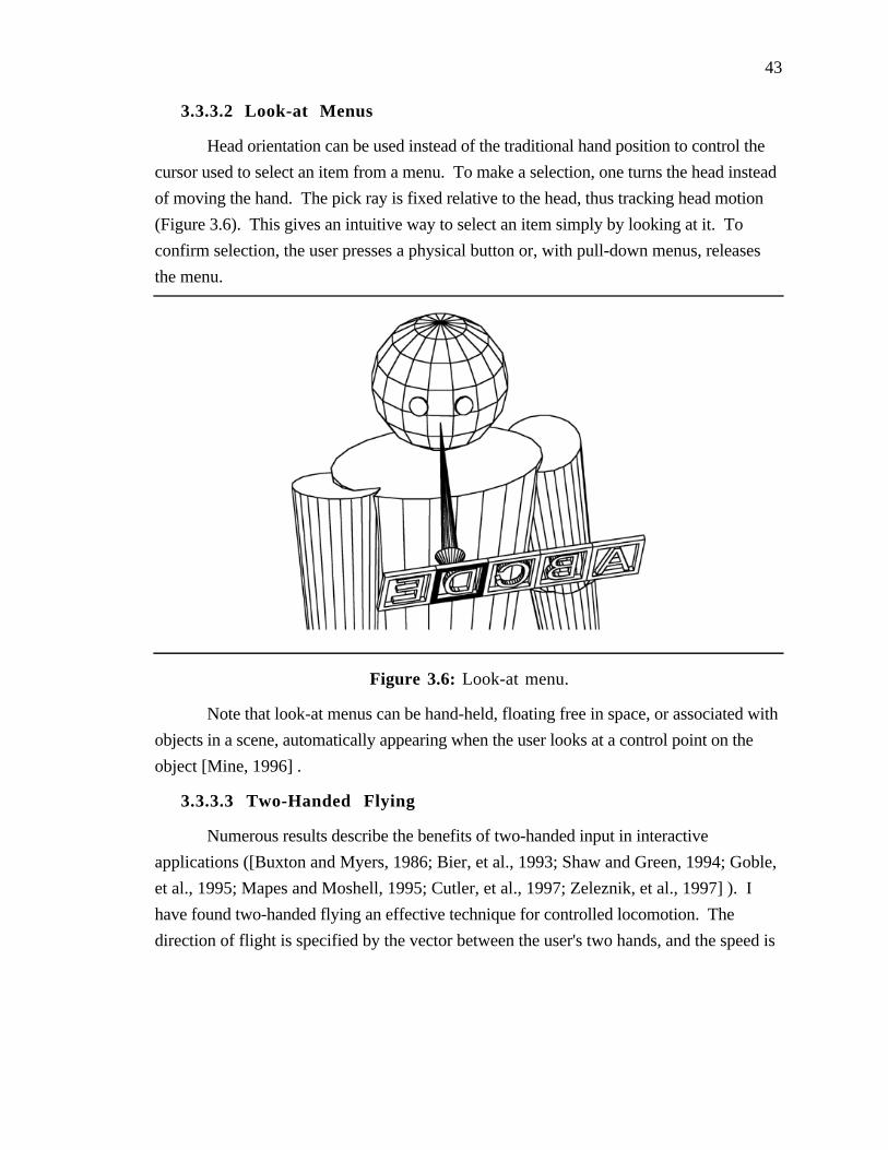
43
3.3.3.2 Look-at Menus
Head orientation can be used instead of the traditional hand position to control the
cursor used to select an item from a menu. To make a selection, one turns the head instead
of moving the hand. The pick ray is fixed relative to the head, thus tracking head motion
(Figure 3.6). This gives an intuitive way to select an item simply by looking at it. To
confirm selection, the user presses a physical button or, with pull-down menus, releases
the menu.
Figure 3.6: Look-at menu.
Note that look-at menus can be hand-held, floating free in space, or associated with
objects in a scene, automatically appearing when the user looks at a control point on the
object [Mine, 1996] .
3.3.3.3 Two-Handed Flying
Numerous results describe the benefits of two-handed input in interactive
applications ([Buxton and Myers, 1986; Bier, et al., 1993; Shaw and Green, 1994; Goble,
et al., 1995; Mapes and Moshell, 1995; Cutler, et al., 1997; Zeleznik, et al., 1997] ). I
have found two-handed flying an effective technique for controlled locomotion. The
direction of flight is specified by the vector between the user's two hands, and the speed is
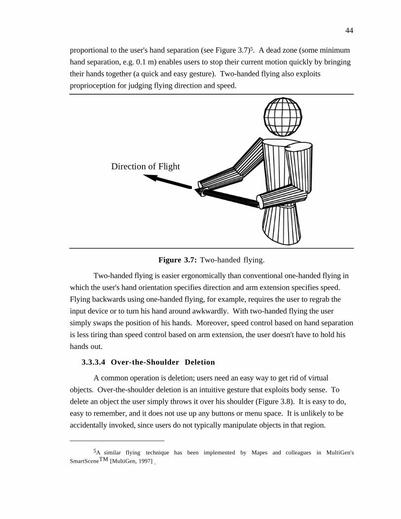
44
proportional to the user's hand separation (see Figure 3.7)5. A dead zone (some minimum
hand separation, e.g. 0.1 m) enables users to stop their current motion quickly by bringing
their hands together (a quick and easy gesture). Two-handed flying also exploits
proprioception for judging flying direction and speed.
Direction of Flight
Figure 3.7: Two-handed flying.
Two-handed flying is easier ergonomically than conventional one-handed flying in
which the user's hand orientation specifies direction and arm extension specifies speed.
Flying backwards using one-handed flying, for example, requires the user to regrab the
input device or to turn his hand around awkwardly. With two-handed flying the user
simply swaps the position of his hands. Moreover, speed control based on hand separation
is less tiring than speed control based on arm extension, the user doesn't have to hold his
hands out.
3.3.3.4 Over-the-Shoulder Deletion
A common operation is deletion; users need an easy way to get rid of virtual
objects. Over-the-shoulder deletion is an intuitive gesture that exploits body sense. To
delete an object the user simply throws it over his shoulder (Figure 3.8). It is easy to do,
easy to remember, and it does not use up any buttons or menu space. It is unlikely to be
accidentally invoked, since users do not typically manipulate objects in that region.
5A similar flying technique has been implemented by Mapes and colleagues in MultiGen's
SmartSceneTM [MultiGen, 1997] .

45
Figure 3.8: Over-the-shoulder deletion.
The space behind a user's head can be treated as a virtual clipboard. A user can
later retrieve the last object deleted by simply reaching over his shoulder and grabbing it.
46
Chapter 4
User Study 1Virtual Object Docking
This chapter presents the results of a user study designed to explore the differences
between manipulating virtual objects that are co-located with one's hand and manipulating
objects at a distance. Would experimental data substantiate the intuition that it is easier to
manipulate an object held in one's hand than it is using some form of remote object
manipulation such as laser beams? I present a description of the experimental design, the
statistical analyses, and some conclusions based upon the results.
4.1 Introduction
The last chapter presented the notion of using automatic scaling to bring remote
objects instantly within reach in a form of remote object manipulation called scaled-world
grab. I recommended scaled-world grab as an effective alternative to remote object
manipulation using laser beams based upon the intuition that it is easier to manipulate an
object held in one's hand than it is to manipulate an object at the end of a beam.
To evaluate quantitatively the differences between manipulating virtual objects held
in one's hand and those at some offset I designed the Virtual Docking Experiment. The
experiment was a repeated measures experiment with three primary experimental
conditions: the manipulation of objects held in one's hand, objects held at a fixed offset,
and objects held at a variable offset. These three conditions were abstractions of three
forms of remote object manipulation: scaled-world grab, laser beam interaction, and
extender grab.
The results confirm that subjects can manipulate objects attached to their hands
more efficiently, as measured by trial completion time, than they can objects at an offset
(either fixed or variable). The mean trial time completion for objects held in one's hand

47
was 3.87 seconds, it was 5.10 seconds for objects held at a fixed offset, and 4.96 seconds
for objects held at a variable offset. No significant difference was found between
manipulating objects at a fixed offset and those at a variable offset.
4.2 Hypotheses
The null hypothesis for this experiment is:
H0: M0 = M1 = M2. In the population, there is no difference between manipulating
a virtual object that is co-located with the hand, one that is offset at some fixed distance,
and one that is at a variable offset which depends on arm extension.
The alternative hypothesis:
H1: M0, M1, and M2 are not all equal. In the population, there is a difference
between manipulating a virtual object that is co-located with the hand, one that is offset at
some fixed distance, and one that is at a variable offset which depends on arm extension.
4.3 The Experiment
4.3.1 Subjects
Eighteen unpaid subjects (7 female, 11 male) were recruited from the staff and
students at the University of North Carolina at Chapel Hill. Staff volunteers were
employees of the university's Administrative Information Services department. Student
volunteers were from an introductory course in computer programming offered by the
university's department of computer science. The subjects received no immediate benefit
from participation in the study, nor were they provided with any tangible inducement for
their participation.
All subjects were right handed. All subjects had experience using conventional
computer interfaces (keyboard, mouse, and monitor) and eleven had limited exposure to
immersive virtual environments (game or demonstration systems). None were regular or
expert users of immersive VR systems.
4.3.2 Experimental Platform
The head-mounted display used for all tests in this study was a Virtual Research
Flight Helmet. Tracking of the subject's head and two hands was performed by a
Polhemus Fastrak magnetic tracker. The magnetic sensor held in the subject's dominant
hand was embedded in a styrofoam cube which measured approximately 1.75 inches on a
48
side. Attached to the magnetic sensor held in the subject's non-dominant hand was a single
input button. Real-time stereoscopic images displayed in the head-mounted display were
generated by UNC's Pixel-Planes 5 graphics computer. The graphics-system update rate
during the experiment was approximately 20 frames/second and the estimated end-to-end
latency was about 80 ms [Mine, 1993] .
The virtual environment consisted of target shapes and hand-held docking shapes.
Target shapes were semi-transparent red cubes floating in space in front of the subject.
Hand-held docking shapes were fully opaque blue cubes attached to the subject's hand.
Docking shapes were either co-located with the subject's dominant hand or at some random
initial offset ranging from 0.1 - 0.6 meters.
4.3.3 The Task
The task given to the subjects was to align the hand-held docking cube with the
target cube floating in space as quickly as possible. The two cubes were considered
aligned if the distance between cube centers was less than 1 cm and the minimum rotation
to align the cubes was less than 10 degrees. The docking cube also had to be moving less
than 5 cm/sec. This velocity threshold was included to encourage more deliberate behavior
on the part of the subjects (i.e. to keep the subject from just waving his hand around
randomly until the cubes were aligned).
Target cubes were presented to the subject one at a time. Each time the subject
successfully aligned the docking cube with the target cube, both the target cube and
docking cube would disappear from their current locations and then reappear in their new
locations. Target cube positions and orientations were randomly generated. The positions
were constrained to fall within a frustum which extended from 0.25 to 0.55 meters in front
of the subject (roughly within the subject's current field of view). Docking cube
orientations matched the orientation of the hand-held styrofoam cube. Docking cube
positions depended upon experimental condition, as explained below.
The subject controlled the virtual docking cube using the small styrofoam cube held
in his dominant hand. Movement of the docking cube in response to movements of the
hand-held styrofoam cube depended upon the experimental condition.
To start the test the subject pressed an input button held in his non-dominant hand.
Once the test had begun the subject's non-dominant hand was no longer used.

49
4.3.4 Experimental Conditions
The experiment compared three conditions: the manipulation of a docking cube co-
located with the subject's hand, the manipulation of a docking cube at a fixed offset from
the subject's hand, and the manipulation of a docking cube at a variable offset from the
subject's hand.
In the co-located condition, the virtual docking cube was co-located with the
styrofoam cube held in the subject's hand (see Figure 4.1a). Changes in position and
orientation of the styrofoam cube were mapped 1:1 onto the position and orientation of the
docking cube. This condition was meant to simulate the manipulation of a virtual object co-
located with one's hand, as is the case in scaled-world grab.
A
C
B
Figure 4.1: Experimental conditions for the docking test. A) Co-located
object B) Fixed-offset object C) Variable-offset object.
In the fixed-offset condition, the virtual docking cube was given a random
horizontal offset from the styrofoam cube for each docking trial (see Figure 4.1b). This
offset would vary from cube to cube (ranging from 0.1 - 0.6 meters) but would remain
fixed during the manipulation of a single cube. Changes in position and orientation of the
styrofoam cube were again mapped 1:1 onto the position and orientation of the docking
50
cube. This condition was meant to simulate the object centered manipulation (see Section
3.2.1) of a remote object that is typical of laser beam interaction.
In the variable-offset condition, the virtual docking cube was given a different
random offset from the styrofoam cube (ranging from 0.1 - 0.6 meters) for each docking
trial, as was the case in the fixed offset condition. In the variable case, however, instead of
being offset horizontally, the docking cube was constrained to lie along the vector from the
subject's head through the magnetic sensor embedded in the styrofoam cube (see Figure
4.1c). This resulted in the docking cube moving with, though at some random offset
behind, the subject's hand as seen from his current point of view. The offset of the
docking cube depended upon the subject's current arm extension. If he halved his arm
extension the distance to the object (along the vector from his head through his hand)
would halve. This condition was meant to simulate the manipulation of an object using
extender grab (see Section 3.2.1).
I included this third condition to see if there were any statistically significant
differences between scaled-world grab and extender grab. I was particularly interested in
this comparison since the two manipulation techniques are quite similar. Both techniques
enable a similar range of manipulation of remote objects, and in both techniques the range
of manipulation depends upon a scale factor which is automatically set based upon object
distance. The primary difference between the two techniques is that in scaled-world grab
the scaling factor is applied to world size, whereas in extender grab it is applied to the
resulting translations of the object.
4.3.5 Experimental Procedure
The study was designed as a single-factor within-subject investigation with repeated
measures. The independent variable was manipulation method; subjects manipulated
docking cubes co-located with their hands, at a fixed offset from their hand, or at a variable
offset from their hand. The dependent variable measured was trial completion time under
each manipulation method.
Each experimental session was preceded by a stereoscopic vision test, a handedness
check, and the signing of a consent form. Prior to the start of the test, subjects were
exposed to a brief (5 minutes) virtual reality demonstration to acclimate them to the virtual
environment system.
A fully counterbalanced design was used. Each subject was tested under all three
experimental conditions. A single test consisted of 36 separate docking trials under a single

51
experimental condition. Subjects were randomly divided into six groups, and each group
was presented the three experimental conditions in one of the six possible orders. Each
subject repeated the chosen sequence of experimental conditions twice (i.e. two blocks:
ABC ABC) for a total of six tests per user. The total number of docking trials performed
by each user was: (2 blocks) * (3 tests/block) * (36 docking trials/test) = 216 docking
trials.
The subjects were permitted to take a short break between tests if necessary.
Following the tests subjects filled out a short questionnaire.
4.4 Results
Time for trial completion was the dependent variable measured for this test. This
was the total time from the appearance of a target cube to the successful alignment of the
docking cube with the target cube.
The results of the first three tests (108 docking trials) were not used in the statistical
analyses below. This decision was based on the results of pilot studies which showed a
marked improvement in performance, which can be attributed to learning, over the first
several trials. Figure 4.2, shows the average docking time, averaged across users and all
techniques, for the 216 trials of the experiment. It shows the same learning behavior the
pilot experiment did.

52
Average Docking Times
Trial
Sec
on
ds
0
5
10
15
20
25
0 50 100 150 200 250
Block 1 Block 2
Figure 4.2: Average trial completion time over all users and all techniques.
The first three tests, therefore, were used as a training period that would allow the
subjects to become familiar with all three techniques before actual performance evaluations.
Table 4.1 presents the overall means obtained from the second block of tests in each
experimental condition. Figure 4.3 presents this information graphically.
Table 4.1: Mean time of trial completion by experimental condition.
Condition Mean (seconds) Standard Deviation (seconds)
Co-located 3.9 2.1
Fixed offset 5.1 3.8
Variable offset 5.0 4.5
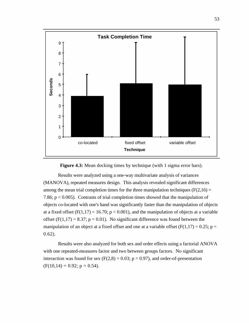
53
Task Completion Time
Technique
Sec
on
ds
0
1
2
3
4
5
6
co-located fixed offset variable offset
7
8
9
Figure 4.3: Mean docking times by technique (with 1 sigma error bars).
Results were analyzed using a one-way multivariate analysis of variances
(MANOVA), repeated measures design. This analysis revealed significant differences
among the mean trial completion times for the three manipulation techniques (F(2,16) =
7.86; p < 0.005). Contrasts of trial completion times showed that the manipulation of
objects co-located with one's hand was significantly faster than the manipulation of objects
at a fixed offset (F(1,17) = 16.70; p < 0.001), and the manipulation of objects at a variable
offset (F(1,17) = 8.37; p = 0.01). No significant difference was found between the
manipulation of an object at a fixed offset and one at a variable offset (F(1,17) = 0.25; p =
0.62).
Results were also analyzed for both sex and order effects using a factorial ANOVA
with one repeated-measures factor and two between groups factors. No significant
interaction was found for sex (F(2,8) = 0.03; p = 0.97), and order-of-presentation
(F(10,14) = 0.92; p = 0.54).
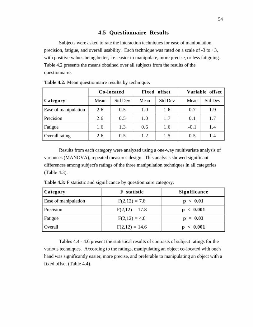
54
4.5 Questionnaire Results
Subjects were asked to rate the interaction techniques for ease of manipulation,
precision, fatigue, and overall usability. Each technique was rated on a scale of -3 to +3,
with positive values being better, i.e. easier to manipulate, more precise, or less fatiguing.
Table 4.2 presents the means obtained over all subjects from the results of the
questionnaire.
Table 4.2: Mean questionnaire results by technique.
Co-located Fixed offset Variable offset
Category Mean Std Dev Mean Std Dev Mean Std Dev
Ease of manipulation 2.6 0.5 1.0 1.6 0.7 1.9
Precision 2.6 0.5 1.0 1.7 0.1 1.7
Fatigue 1.6 1.3 0.6 1.6 -0.1 1.4
Overall rating 2.6 0.5 1.2 1.5 0.5 1.4
Results from each category were analyzed using a one-way multivariate analysis of
variances (MANOVA), repeated measures design. This analysis showed significant
differences among subject's ratings of the three manipulation techniques in all categories
(Table 4.3).
Table 4.3: F statistic and significance by questionnaire category.
Category F statistic Significance
Ease of manipulation F(2,12) = 7.8 p < 0.01
Precision F(2,12) = 17.8 p < 0.001
Fatigue F(2,12) = 4.8 p = 0.03
Overall F(2,12) = 14.6 p < 0.001
Tables 4.4 - 4.6 present the statistical results of contrasts of subject ratings for the
various techniques. According to the ratings, manipulating an object co-located with one's
hand was significantly easier, more precise, and preferable to manipulating an object with a
fixed offset (Table 4.4).

55
Table 4.4: Co-located vs. fixed-offset, F statistic and significance by questionnaire
category.
Category F statistic Significance
Ease of manipulation F(1,13) = 14.3 p < 0.005
Precision F(1,13) = 14.0 p < 0.005
Fatigue F(1,13) = 3.1 p = 0.10
Overall F(1,13) = 15.2 p < 0.005
Manipulating an object co-located with one's hand was significantly easier, more
precise, less fatiguing, and preferable to manipulating an object with a variable offset
(Table 4.5).
Table 4.5: Co-located vs. variable-offset, F statistic and significance by questionnaire
category.
Category F statistic Significance
Ease of manipulation F(1,13) = 13.7 p < 0.005
Precision F(1,13) = 28.8 p < 0.001
Fatigue F(1,13) = 10.1 p < 0.01
Overall F(1,13) = 30.7 p < 0.001
No significant differences were found between the manipulation of an object at a
fixed offset and one at a variable offset (Table 4.6).
Table 4.6: Fixed-offset vs. variable-offset, F statistic and significance by questionnaire
category.
Category F statistic Significance
Ease of manipulation F(1,13) = 0.6 p = 0.47
Precision F(1,13) = 2.0 p = 0.18
Fatigue F(1,13) = 2.5 p = 0.14
Overall F(1,13) = 4.2 p = 0.056
56
4.6 Discussion
This evidence strongly supports the hypothesis that the manipulation of an object
co-located with one's hand is more efficient than the manipulation of an object at an offset.
Subjects were able to place the hand-held docking cube within the target cube significantly
faster when the docking cube was co-located with their hand then they could when it lay at
some offset (either fixed or variable). Furthermore, based on the results of the
questionnaire, subjects preferred the manipulation of an object co-located with their hand,
rating it significantly higher than the manipulation of an object with an offset. No
significant difference was found between the manipulation of an object with a fixed offset
and one with a variable offset in task completion time or the results of the questionnaire.
Subjects' written comments also reflected the preference for the manipulation of an
object co-located with one's hand. Several subjects described it as being "the most natural"
or "much more natural" and stated that it gave them a "feeling of exact control". Other
comments included, "I liked it when the object was at my hand the best", and "It reacts just
like I think its going to".
When manipulating an object with an offset there was "more of a sense of
detachment from the manipulator cube". In general, subjects disliked offsets, stating that
they "had more feeling of being too detached" and that they felt it was "more awkward to
control and more tiring".
Some subjects felt that the manipulation of objects with a fixed offset got easier
with time. One subject said, "Fixed offset is okay once you get used to it", while another
said, "I liked the object at a fixed offset once I got used to it".
One subject did prefer the manipulation of objects with a variable offset "because of
speed" but most others felt variable offset was harder to control. Comments included, "I
was just chasing cubes", and "With the variable offset you can't get used to the 'feel',
constantly having to adjust".
4.7 Conclusion
Statistical results and test-subject comments indicate that there is a difference
between manipulating an object co-located with one's hand and manipulating an object at
some offset, either fixed or variable. In fact, the results show that subjects can position an
object faster when it is co-located with their hand and that they find that form of interaction
57
easier, and more precise. No statistically significant difference was shown between the
manipulation of objects at a fixed offset and a variable offset.
These results support the notion presented in Chapter 3 that it is better to manipulate
objects within arm's reach, as is done in scaled-world grab. Recall that in scaled-world
grab, objects are automatically brought within reach by scaling down the world about the
user's head every time he grabs an object. Since the manipulandum is at the user's hand,
he has a greater sense of control and can position it more rapidly than he can when it is at
some offset, either fixed, as is the case in laser beam interaction, or variable, as is the case
in extender grab.
The results, however, do not measure the effects of automatic scaling on the user's
ability to manipulate objects. They show that when objects are co-located with the user's
hand, which is the case after automatic scaling, he can manipulate them faster than when
they are at some offset.
I excluded automatic scaling from the experiment because I wanted to compare the
benefits of in-hand manipulation with at-offset manipulation independently of the particular
technique used to bring an object within reach; automatic-scaling is only one of potentially
many different ways to manipulate an object within arm's reach. In addition, the exclusion
of automatic scaling simplified the experimental design. It is difficult to isolate the effects
of automatic scaling from other potentially confounding factors such as object selection
(scaled-world grab, for example, is tightly coupled with occlusion selection). Future
experiments should be conducted to evaluate the differences between manipulation with and
without automatic scaling.

58
Chapter 5
User Study 2Proprioception and
Virtual Widget Interaction
This chapter presents the results of a user study developed to explore the
differences between interacting with a widget held in one's hand and interacting with a
widget floating in space. The hypothesis was that it would be easier for subjects to interact
with hand-held widgets than it would be for them to interact with widgets floating in space.
I present a description of the experimental design, the statistical analyses, and some
conclusions based upon the results.
5.1 Introduction
The virtual widget experiment evaluated the merits of using hand-held widgets,
virtual controllers held in the user's hand. Chapter three presented hand-held widgets as an
alternative to conventional widgets that are co-located with the object they control. I
asserted that widgets held in one's hand are easier to locate, access, and use. This was
because one could augment visual information on the location of a widget and its
affordances with proprioceptive cues. To evaluate how well a subject could take advantage
of proprioceptive cues when interacting with widgets, I measured how well he could return
his hand to a known point on a virtual widget without visual feedback. Using a repeated
measures design, I measured subject performance under two experimental conditions,
widget held in hand and widget fixed in space. Note that this experiment deals directly
only with the first two aspects of my claim, the relative ease with which a user can locate
and access a hand-held widget.
This experiment is similar to an experiment performed by Ken Hinkley of the
University of Virginia as part of his research for his doctoral dissertation. The primary

59
difference is that in his experiment subjects worked through-the-window and in my
experiment they worked immersed, wearing a head-mounted display. In [Hinkley, 1996] .
he presents the results of his study of using two hands in the manipulation of virtual
objects. His task consisted of two phases. The first phase involved the manipulation of
two virtual objects using two hand-held props. The second phase consisted of a "memory
test" where users tried to reproduce the placement of the dominant hand without any visual
feedback. He compared two experimental conditions, a unimanual case in which the
subject could manipulate only one device at a time and a bimanual case where the subject
manipulated both devices simultaneously. He found that two hands together form a frame
of reference which was independent of visual feedback. His conclusion was that when
both hands can be involved in a manipulation, the user may not have to maintain visual
attention constantly.
The results of my experiment strongly support the results of Hinkley. Subjects
were able to return to a position relative to their own hand much more precisely than they
could to a position in space.
5.2 Hypotheses
The null hypothesis for this experiment is:
H0: M0 = M1. In the population, there is no difference between interacting with a
virtual widget that is held in your hand versus one that is floating in space.
The alternative hypothesis:
H1: M0 ≠ M1. In the population, there is a difference between interacting with a
virtual widget that is held in your hand versus one that is floating in space.
5.3 The Experiment
5.3.1 Subjects
Eighteen unpaid subjects (7 female, 11 male) were recruited from the staff and
students at the University of North Carolina at Chapel Hill. These were the same subjects
who performed the docking experiment presented in Chapter 4. Staff volunteers were
employees of the University's Administrative Information Services department. Student
volunteers were from an introductory course in computer programming offered by the
university's department of computer science. The subjects received no immediate benefit

60
from participation in the study, nor were they provided with any tangible inducement for
their participation.
All subjects were right handed. All subjects had experience using conventional
computer interfaces (keyboard, mouse, and monitor). Prior to the docking test, which all
subjects performed first, only eleven had limited exposure to immersive virtual
environments (game or demonstration systems). None were regular or expert users of
immersive VR systems.
5.3.2 Experimental Platform
The head-mounted display used for all tests in this study was a Virtual Research
Flight Helmet. Tracking of the subject's head and two hands was performed by a
Polhemus Fastrak magnetic tracker. Attached to the magnetic sensor held in the subject's
dominant hand was a single input button. The sensor held in the subject's non-dominant
hand (for only one of the two experimental conditions) was embedded in a styrofoam cube
which measured approximately 1.75 inches on a side. Real-time stereoscopic images
displayed in the head-mounted display were generated by UNC's Pixel-Planes 5 graphics
computer. The graphics-system update rate during the experiment was approximately 20
frames/second and the estimated end-to-end latency was about 80 ms [Mine, 1993] .
Figure 5.1: Widget test objects.
The virtual environment consisted of a virtual widget, a current-color indicator, a
three-dimensional cursor, and target cubes (Figure 5.1). The virtual widget consisted of
three orthogonal rods with colored spheres at each end (for a total of six spheres). Each

61
sphere represented a single affordance or handle of the virtual widget. Depending upon the
experimental condition, the virtual widget was either attached to the subject's non-dominant
hand or was fixed floating in space (Figure 5.2). The current-color indicator was an
additional colored sphere that was fixed in the upper right hand corner of the subject's
display. This displayed the color of the target sphere, the next handle on the widget to be
selected by the subject. The subject selected the handle using the three-dimensional cursor,
a small sphere attached to the subject's dominant hand. Also included in the environment
were target cubes, red semi-transparent cubes which appeared at random positions and
orientations about the subject.
5.3.3 The Task
Each trial was divided into three phases. First, the subject moves the 3D cursor to
the specified handle on the virtual widget (one of the six colored spheres). Next, he
performs an unrelated abstract task (moving his hand from the widget to a target cube and
clicking on the input button). Finally, he returns his hand as closely as possible to the
handle specified in phase one, without visual feedback. Subjects were instructed that for
this test, accuracy was more important than speed. The test is now described in more
detail.
For the first phase of each trial the current-color indicator displayed a different color
from a random sequence of colors. This color matched the color of one of the six spheres
on the virtual widget. The subject was instructed to move the 3D cursor held in his
dominant hand to the correspondingly colored sphere on the widget and then click on the
input button. If the 3D cursor was close enough to the correct sphere when the subject
clicked on the button, the sphere would turn black to signal success. If the cursor was not
close enough, he had to try again.
Once the subject successfully clicked on the correctly colored sphere, a semi-
transparent cube appeared at some random position in space. Once the subject determined
the location of the cube, he reached inside of it, and clicked his input button. This would
make the cube, the widget, and the three-dimensional cursor all disappear from view.
This began the final phase of the trial, in which the subject was required to return
his hand, without visual feedback, to the position of the last colored sphere he clicked on.
When he felt he had returned to the original position he pressed the button for a third time,
at which point the system recorded the current offset of the cursor from the actual position
of the sphere.

62
5.3.4 Experimental Procedure
The study was designed as a single-factor within-subject investigation with repeated
measures. The independent variable was location of the virtual widget, which took the
nominal values of hand-held or fixed in space (see Figure 5.2). When hand-held the
widget co-located with to the styrofoam cube held in the subject's non-dominant hand.
When fixed-in-space the widget was set at a fixed height above the ground that was easy
for the user to reach.
A B
Figure 5.2: Widget test experimental conditions: A) The hand-held widget
was attached the subject's non-dominant hand (the subject's left hand in the
diagram) and moved as the hand moved. B) The in-space widget floated at
a fixed point in space in front of the subject and did not move when the
subject moved his hand.
The dependent variable measured was the positional accuracy with which the user
could return his hand to a point in space. For hand-held widgets this point was relative to
the styrofoam cube held in the subject's hand and thus would move during the trial as the
subject moved his hand. This point would not move when the widget was fixed in space.
Each experimental session was preceded by a stereoscopic vision test, a handedness
check, and the signing of a consent form.
A fully counterbalanced design was used. Each subject was tested under both
experimental conditions. A single test consisted of 30 separate widget tasks under a single
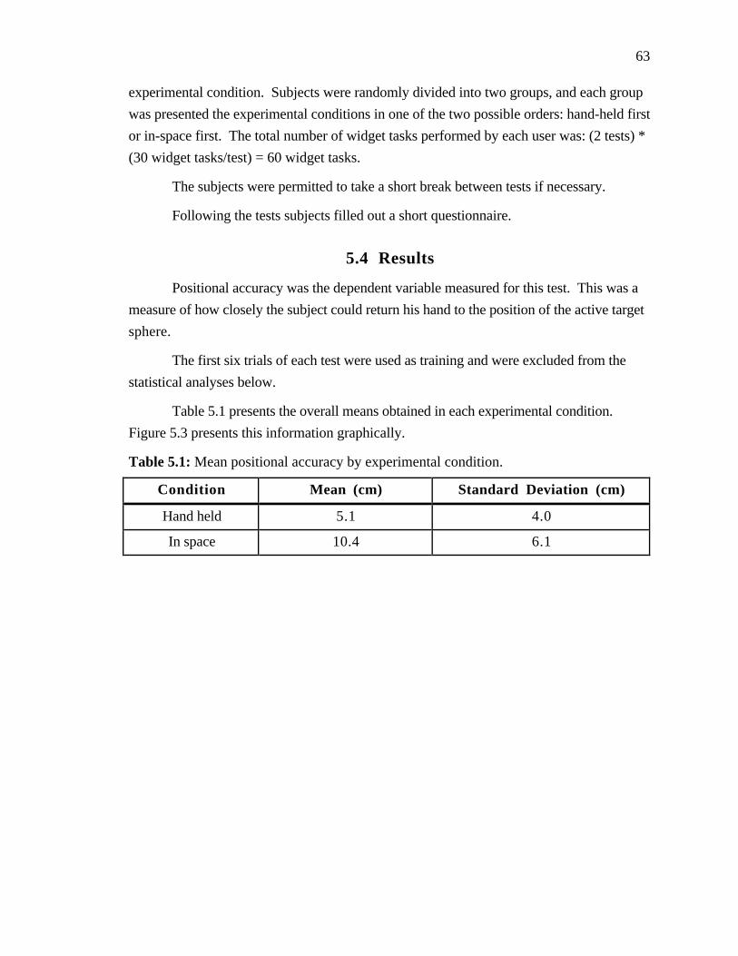
63
experimental condition. Subjects were randomly divided into two groups, and each group
was presented the experimental conditions in one of the two possible orders: hand-held first
or in-space first. The total number of widget tasks performed by each user was: (2 tests) *
(30 widget tasks/test) = 60 widget tasks.
The subjects were permitted to take a short break between tests if necessary.
Following the tests subjects filled out a short questionnaire.
5.4 Results
Positional accuracy was the dependent variable measured for this test. This was a
measure of how closely the subject could return his hand to the position of the active target
sphere.
The first six trials of each test were used as training and were excluded from the
statistical analyses below.
Table 5.1 presents the overall means obtained in each experimental condition.
Figure 5.3 presents this information graphically.
Table 5.1: Mean positional accuracy by experimental condition.
Condition Mean (cm) Standard Deviation (cm)
Hand held 5.1 4.0
In space 10.4 6.1
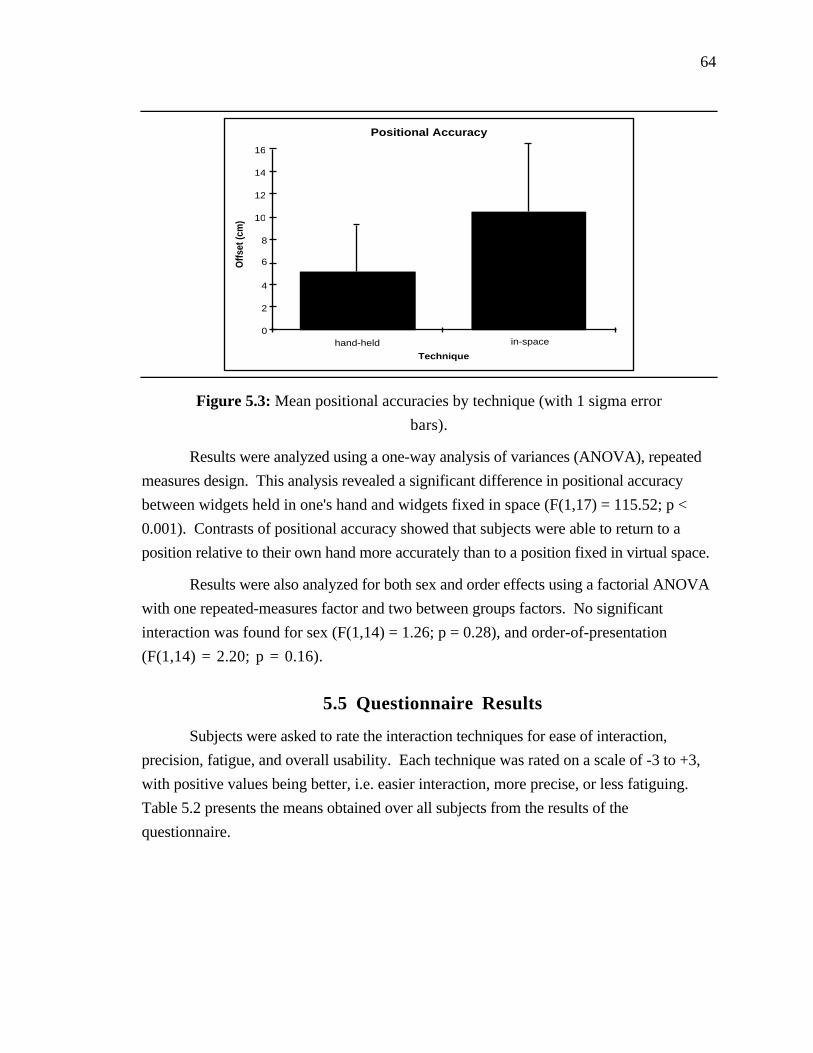
64
Positional Accuracy
Technique
Offs
et (c
m)
0
2
4
6
8
10
12
hand-held in-space
14
16
Figure 5.3: Mean positional accuracies by technique (with 1 sigma error
bars).
Results were analyzed using a one-way analysis of variances (ANOVA), repeated
measures design. This analysis revealed a significant difference in positional accuracy
between widgets held in one's hand and widgets fixed in space (F(1,17) = 115.52; p <
0.001). Contrasts of positional accuracy showed that subjects were able to return to a
position relative to their own hand more accurately than to a position fixed in virtual space.
Results were also analyzed for both sex and order effects using a factorial ANOVA
with one repeated-measures factor and two between groups factors. No significant
interaction was found for sex (F(1,14) = 1.26; p = 0.28), and order-of-presentation
(F(1,14) = 2.20; p = 0.16).
5.5 Questionnaire Results
Subjects were asked to rate the interaction techniques for ease of interaction,
precision, fatigue, and overall usability. Each technique was rated on a scale of -3 to +3,
with positive values being better, i.e. easier interaction, more precise, or less fatiguing.
Table 5.2 presents the means obtained over all subjects from the results of the
questionnaire.
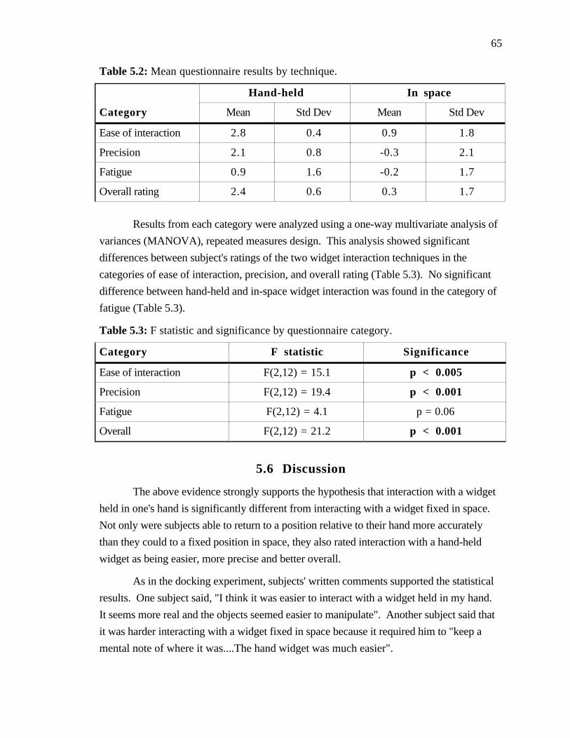
65
Table 5.2: Mean questionnaire results by technique.
Hand-held In space
Category Mean Std Dev Mean Std Dev
Ease of interaction 2.8 0.4 0.9 1.8
Precision 2.1 0.8 -0.3 2.1
Fatigue 0.9 1.6 -0.2 1.7
Overall rating 2.4 0.6 0.3 1.7
Results from each category were analyzed using a one-way multivariate analysis of
variances (MANOVA), repeated measures design. This analysis showed significant
differences between subject's ratings of the two widget interaction techniques in the
categories of ease of interaction, precision, and overall rating (Table 5.3). No significant
difference between hand-held and in-space widget interaction was found in the category of
fatigue (Table 5.3).
Table 5.3: F statistic and significance by questionnaire category.
Category F statistic Significance
Ease of interaction F(2,12) = 15.1 p < 0.005
Precision F(2,12) = 19.4 p < 0.001
Fatigue F(2,12) = 4.1 p = 0.06
Overall F(2,12) = 21.2 p < 0.001
5.6 Discussion
The above evidence strongly supports the hypothesis that interaction with a widget
held in one's hand is significantly different from interacting with a widget fixed in space.
Not only were subjects able to return to a position relative to their hand more accurately
than they could to a fixed position in space, they also rated interaction with a hand-held
widget as being easier, more precise and better overall.
As in the docking experiment, subjects' written comments supported the statistical
results. One subject said, "I think it was easier to interact with a widget held in my hand.
It seems more real and the objects seemed easier to manipulate". Another subject said that
it was harder interacting with a widget fixed in space because it required him to "keep a
mental note of where it was....The hand widget was much easier".
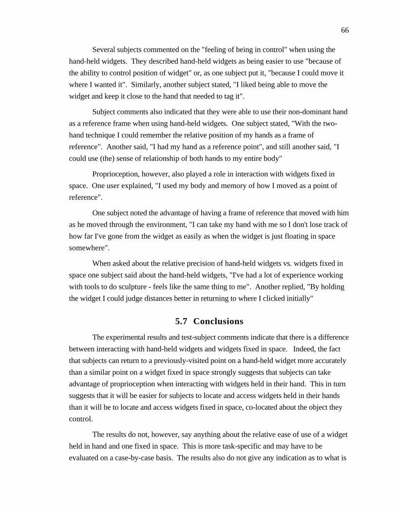
66
Several subjects commented on the "feeling of being in control" when using the
hand-held widgets. They described hand-held widgets as being easier to use "because of
the ability to control position of widget" or, as one subject put it, "because I could move it
where I wanted it". Similarly, another subject stated, "I liked being able to move the
widget and keep it close to the hand that needed to tag it".
Subject comments also indicated that they were able to use their non-dominant hand
as a reference frame when using hand-held widgets. One subject stated, "With the two-
hand technique I could remember the relative position of my hands as a frame of
reference". Another said, "I had my hand as a reference point", and still another said, "I
could use (the) sense of relationship of both hands to my entire body"
Proprioception, however, also played a role in interaction with widgets fixed in
space. One user explained, "I used my body and memory of how I moved as a point of
reference".
One subject noted the advantage of having a frame of reference that moved with him
as he moved through the environment, "I can take my hand with me so I don't lose track of
how far I've gone from the widget as easily as when the widget is just floating in space
somewhere".
When asked about the relative precision of hand-held widgets vs. widgets fixed in
space one subject said about the hand-held widgets, "I've had a lot of experience working
with tools to do sculpture - feels like the same thing to me". Another replied, "By holding
the widget I could judge distances better in returning to where I clicked initially"
5.7 Conclusions
The experimental results and test-subject comments indicate that there is a difference
between interacting with hand-held widgets and widgets fixed in space. Indeed, the fact
that subjects can return to a previously-visited point on a hand-held widget more accurately
than a similar point on a widget fixed in space strongly suggests that subjects can take
advantage of proprioception when interacting with widgets held in their hand. This in turn
suggests that it will be easier for subjects to locate and access widgets held in their hands
than it will be to locate and access widgets fixed in space, co-located about the object they
control.
The results do not, however, say anything about the relative ease of use of a widget
held in hand and one fixed in space. This is more task-specific and may have to be
evaluated on a case-by-case basis. The results also do not give any indication as to what is

67
the best method for selecting and switching among the various widgets available in an
application. Further experiments are required to evaluate the relative merits of techniques
such as conventional toolbars and pull-down menus, and newer techniques such as look-at
menus (Chapter 3) and Kurtenbach's marking menus [Kurtenbach and Buxton, 1993] .

68
Chapter 6
CHIMPThe Chapel Hill
Immersive Modeling Program
This chapter presents a description of CHIMP, the Chapel Hill Immersive Modeling
Program. CHIMP is an immersive system intended for the preliminary stages of
architectural design. The main goal during the development of the CHIMP system has
been the creation of an integrated set of virtual-environment interaction techniques that
exploit the benefits of working immersed while compensating for its limitations. I present
an overview of the CHIMP system and discuss several relevant aspects of the CHIMP
design.
6.1 CHIMP Overview
In the CHIMP system users create and manipulate models while immersed within a
virtual world, as opposed to the customary through-the window computer-aided design
(CAD) environment. CHIMP includes both one and two-handed interaction techniques,
minimizes unnecessary user interaction, and takes advantage of the head-tracking and
immersion provided by the virtual environment system.
Figure 6.1 shows the author using the CHIMP system. The hardware
configuration includes an immersive head-mounted display, a magnetic tracking system
with three 6 degree-of-freedom (DoF) sensors (one for the head and one for each hand),
two separate input devices (one for each hand) and a high speed graphics computer (Pixel-
Planes 5, see [Fuchs, et al., 1989] ).
Figure 6.2 shows the two input devices in detail. The user holds the primary input
device in his dominant hand and the secondary input device in his non-dominant hand. The
primary input device is a modified handle of a commercial joystick with five buttons (only

69
three are used in the CHIMP system). The secondary input device is a custom built device
with two buttons.
Figure 6.1: Using the CHIMP system.
Figure 6.2: CHIMP's primary (shown on the right) and secondary
(shown on the left) input devices.

70
Table 6.1 presents an overview of the CHIMP's features.
Table 6.1: CHIMP system overview.
Object Generation Rectangular solidCylinderConeSphere2D/3D pathLibrary object
Derivative Object Generation Surface of revolution6 DoF Manipulation Scaled-world grab
Extender grabSelection Occlusion selection
Spotlight selection2D multiselect3D multiselect
Object Transformation 1D/2D/3D translate1D/3D rotate3D scaleDuplicateSet center of rotation/scalingAlign centers/extents
Surface Attribute Control Color sampleColor set
Viewpoint Manipulation Pan (scaled-world grab)Two-handed flyOrbital modeHead-butt zoomDynamic Scaling
Snaps GridGround planeBounding box vertexBounding box edgeMidpoint bounding box edgeBounding box faceCenter bounding box faceBounding box normalBounding box orientation
Object control Numeric input (interactive numbers)
There are four primary forms of interaction in CHIMP:
• object selection/manipulation
• object generation
• object transformation
• viewpoint manipulation
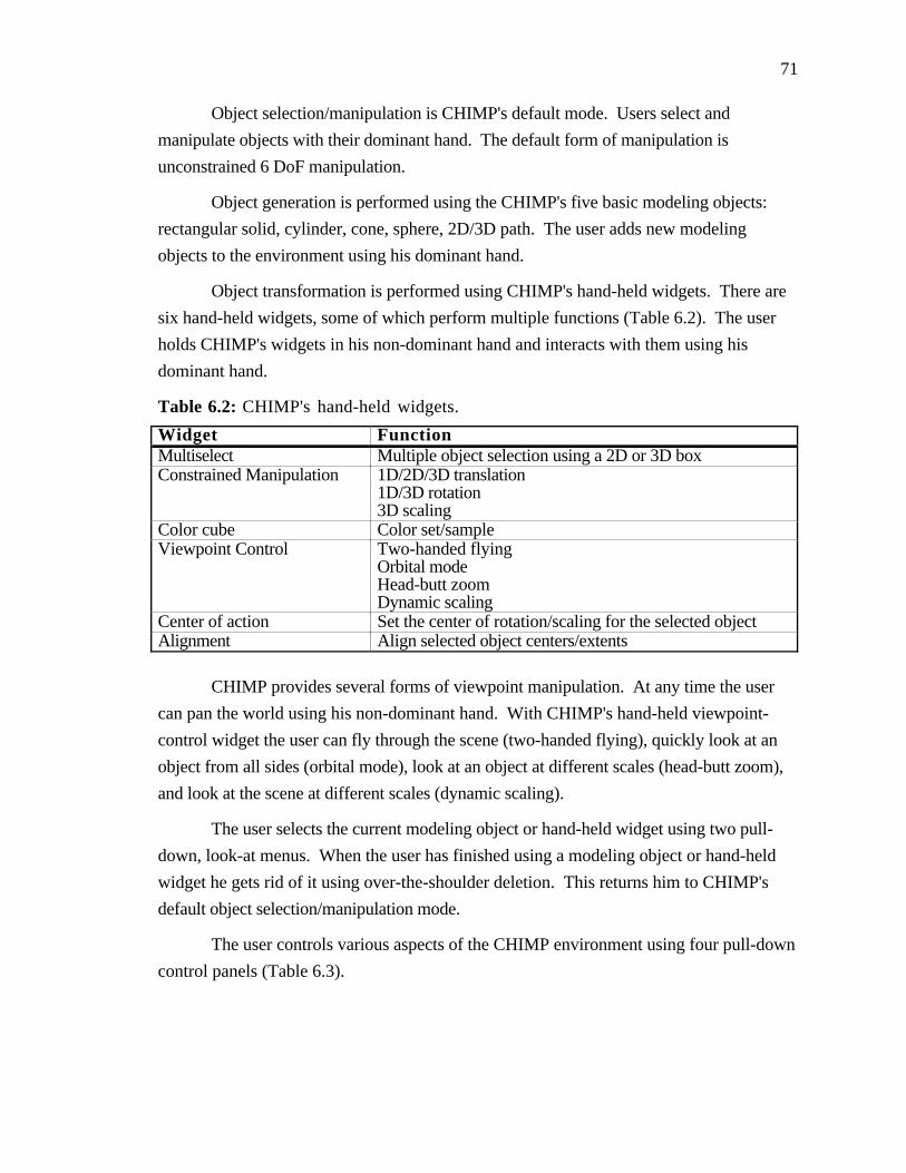
71
Object selection/manipulation is CHIMP's default mode. Users select and
manipulate objects with their dominant hand. The default form of manipulation is
unconstrained 6 DoF manipulation.
Object generation is performed using the CHIMP's five basic modeling objects:
rectangular solid, cylinder, cone, sphere, 2D/3D path. The user adds new modeling
objects to the environment using his dominant hand.
Object transformation is performed using CHIMP's hand-held widgets. There are
six hand-held widgets, some of which perform multiple functions (Table 6.2). The user
holds CHIMP's widgets in his non-dominant hand and interacts with them using his
dominant hand.
Table 6.2: CHIMP's hand-held widgets.
Widget FunctionMultiselect Multiple object selection using a 2D or 3D boxConstrained Manipulation 1D/2D/3D translation
1D/3D rotation3D scaling
Color cube Color set/sampleViewpoint Control Two-handed flying
Orbital modeHead-butt zoomDynamic scaling
Center of action Set the center of rotation/scaling for the selected objectAlignment Align selected object centers/extents
CHIMP provides several forms of viewpoint manipulation. At any time the user
can pan the world using his non-dominant hand. With CHIMP's hand-held viewpoint-
control widget the user can fly through the scene (two-handed flying), quickly look at an
object from all sides (orbital mode), look at an object at different scales (head-butt zoom),
and look at the scene at different scales (dynamic scaling).
The user selects the current modeling object or hand-held widget using two pull-
down, look-at menus. When the user has finished using a modeling object or hand-held
widget he gets rid of it using over-the-shoulder deletion. This returns him to CHIMP's
default object selection/manipulation mode.
The user controls various aspects of the CHIMP environment using four pull-down
control panels (Table 6.3).

72
Table 6.3: CHIMP's control panels.
Control Panel FunctionMain • Quit
• Cut, copy, paste• Duplicate,delete• Select/deselect all• Group/ungroup• Undo/redo• Reset user/object position/scale• Multiselect fence mode• New object extents mode• Set object color
Snap • Position• Center• Vertex• Midline• Edge• Face• Grid• Ground plane
• Orientation• Bounding box normal• Bounding box orientation• Grid orientation
• Snap distanceGrid • Translation grid spacing (X,Y,Z)
• Orientation grid spacingNumeric Control • Object position (X,Y,Z)
• Object orientation (R,P,Y)• Object scale (X,Y,Z)
I have used the CHIMP system as a testbed for the evaluation of virtual-
environment interaction techniques. I consider CHIMP a suitable testbed since computer-
aided modeling for the preliminary stages of architectural design is a real-world problem
that depends on the complex six degree-of-freedom manipulation of objects and shapes and
intuitive viewpoint specification.
The design of CHIMP is the end product of several years of research into virtual
environment interaction techniques. The following sections describe some of the more
interesting aspects of CHIMP's design and present some of the lessons learned during the
development of CHIMP about working in a virtual world.
One of the first tasks I undertook as part of my dissertation research was a review
of the state of the art in computer-aided modeling. The results of my review are presented
in Appendix A.
73
Section 6.2 discusses the challenge of mode control in complex virtual-environment
applications such as CHIMP.
Sections 6.3 - 6.5 discuss issues concerning object selection, manipulation, and
generation.
Section 6.6 gives a brief history of the development of CHIMP's constrained
motion widgets, one of the primary techniques used for the controlled transformation of
CHIMP objects.
Finally, Section 6.7 discusses numeric input in a virtual world.
6.2 Managing Modes
Most complex applications such as CHIMP rely on a large assortment of tools and
modes. Developing effective techniques for managing these modes is one of the most
difficult challenges facing developers of virtual-environment applications. Several factors
contribute to this situation.
First of all, most immersive virtual-environment systems are limited in terms of the
forms and rates of input information that are available. Wearing a non-transparent head-
mounted display and standing free in the VR environment makes it nearly impossible to use
conventional keyboards, mice, or slider-button boxes effectively. This makes it difficult to
use traditional techniques for mode control and interaction such as hot keys, command
strings, numeric input, and interactive dials. Available inputs such as gestures and the
buttons on hand-held input devices must be used differently for many different forms of
interaction and quickly become overloaded. In informal user trials I have observed that this
results in user confusion; users often forget which button or gesture invokes a specific
function.
Secondly, conventional two-dimensional graphical user interface (GUI) elements
(such as toolbars, menus, and dialog boxes) used for mode control and interaction in
through-the-window environments are difficult to use in a virtual world. Whereas it is
possible to create three-dimensional equivalents of many of these GUI elements, their lack
of haptic feedback, their higher dimensionality, and the limitations in display space and
display resolution all complicate and slow user interaction.
Finally, users are still unfamiliar with virtual environments and the new virtual-
environment-specific interaction techniques. The years of experience users have using
conventional through-the-window computer applications typically do not apply to working
in a virtual world and in some cases actually confound the use of VR systems.

74
The remainder of this section describes several of the techniques I have
experimented with for selecting tools and controlling modes in virtual environment
applications. I include discussions of the merits and limitations of each technique. Though
each technique has its advantages (such as simplicity, familiarity, or ease of use), none is
totally satisfactory. The most common problem is lack of scalability—the number of
modes or tools that can be reasonably selected using the technique is limited. Another
problem is ease of use. Though virtual menus and control panels are familiar and scalable,
for example, they are often difficult and frustrating to use in a virtual world.
6.2.1 Rotary Tool Chooser
One of the first techniques I developed for switching between high level tools (such
as fly, grab, and select) I called the Rotary Tool Chooser (RTC). The rotary tool chooser
was a one-dimensional menu based upon J.D. Liang's ring menu [Liang 1994]. A one-
dimensional menu is one in which a user has to vary only one degree of freedom to move
between menu selections [Mine 1995].
To invoke the RTC the user presses a button on his input device. This results in the
available tools being displayed in an arc about the user's hand (Figure 6.3). To select a
tool the user simply rotates his hand, like turning a dial, until the desired tool falls within
the selection box. To confirm his selection the user releases the input button.
Figure 6.3: Rotary tool chooser.
Instead of being centered about the user's hand, the arc of items can appear in front
of the user's face, locked in head space. I have found this to improve interaction with the
RTC since the user no longer has to bring his hand into view in order to see the chooser.
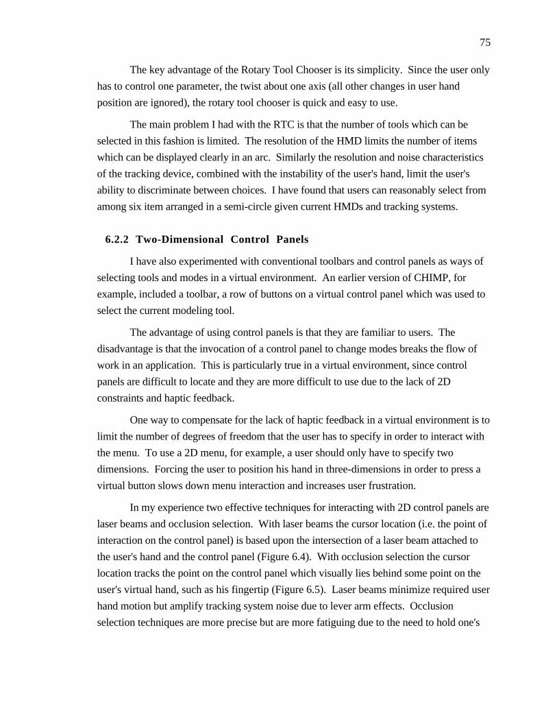
75
The key advantage of the Rotary Tool Chooser is its simplicity. Since the user only
has to control one parameter, the twist about one axis (all other changes in user hand
position are ignored), the rotary tool chooser is quick and easy to use.
The main problem I had with the RTC is that the number of tools which can be
selected in this fashion is limited. The resolution of the HMD limits the number of items
which can be displayed clearly in an arc. Similarly the resolution and noise characteristics
of the tracking device, combined with the instability of the user's hand, limit the user's
ability to discriminate between choices. I have found that users can reasonably select from
among six item arranged in a semi-circle given current HMDs and tracking systems.
6.2.2 Two-Dimensional Control Panels
I have also experimented with conventional toolbars and control panels as ways of
selecting tools and modes in a virtual environment. An earlier version of CHIMP, for
example, included a toolbar, a row of buttons on a virtual control panel which was used to
select the current modeling tool.
The advantage of using control panels is that they are familiar to users. The
disadvantage is that the invocation of a control panel to change modes breaks the flow of
work in an application. This is particularly true in a virtual environment, since control
panels are difficult to locate and they are more difficult to use due to the lack of 2D
constraints and haptic feedback.
One way to compensate for the lack of haptic feedback in a virtual environment is to
limit the number of degrees of freedom that the user has to specify in order to interact with
the menu. To use a 2D menu, for example, a user should only have to specify two
dimensions. Forcing the user to position his hand in three-dimensions in order to press a
virtual button slows down menu interaction and increases user frustration.
In my experience two effective techniques for interacting with 2D control panels are
laser beams and occlusion selection. With laser beams the cursor location (i.e. the point of
interaction on the control panel) is based upon the intersection of a laser beam attached to
the user's hand and the control panel (Figure 6.4). With occlusion selection the cursor
location tracks the point on the control panel which visually lies behind some point on the
user's virtual hand, such as his fingertip (Figure 6.5). Laser beams minimize required user
hand motion but amplify tracking system noise due to lever arm effects. Occlusion
selection techniques are more precise but are more fatiguing due to the need to hold one's

76
hand up over the control panel and the larger hand motions required to reach all points on
the control panel.
Figure 6.4: Interacting with a control panel using a laser beam.
Figure 6.5: Interacting with a control panel using occlusion selection.

77
6.2.3 Look-at Menus
More recently I have found that interaction and mode selection in a virtual world can
be enhanced if one takes advantage of additional user output channels. The look-at menus
technique presented in Chapter 3 allows users to select among a limited set of options using
just head motion. As described in that chapter, the currently selected object in a menu
depends upon the current orientation of the users head. By moving his head the user can
move from item to item within a menu.
CHIMP includes two look-at menus which are used to select the current hand-held
widget and the current modeling object (Figure 6.6). The user selects items from these
menus using his head motion.
Figure 6.6: CHIMP's look-at menus used to select current hand-held
widget (left) and modeling object (right). The circular crosshairs cursor
moves with the user's head.
6.2.4 Pull-Down Menus
As described in Chapter 3, menus and control panels are easier to find if they are
stored relative to the user's body. Currently, CHIMP's four control panels and two look-at
menus are stored just above the user's field of view as a set of pull-down menus. This
makes them easy to access and eliminates problems of obscuration of the scene by the
menus.
Since the menus are pull-down menus that move with the user as he moves through
the environment they are easy to locate and access. Whenever the user needs a menu he
simply reaches up and pulls it into view. He does not have to search through the
environment to find it. Once he has finished using a menu, he releases it, at which point it
floats back up to its body-relative hiding place.

78
Though pull-down menus are easy to acquire, the number of items that can be
reasonably be stored above the user's field of view is limited. In informal user trials I have
found that one can reasonably store three menus above one's field of view (one to the left,
one directly above, and one to the right of the current view direction). To access many
more menus than that requires some supplemental form of menu selection. In the CHIMP
system, for example, the four control panels (Table 6.3) are condensed into a single pull-
down item. When the user reaches up and pulls down a control panel, he pulls down a
single panel (the last one he used). A set of buttons found at the bottom of each panel is
used to access the other three panels.
As an alternative to using a row of buttons I have considered using some more
scalable form of menu selection such as Kurtenbach's Marking Menus [Kurtenbach and
Buxton, 1993] . Instead of pressing a button to switch between menus the user might
instead make the appropriate marking gesture (Chapter 2). A two level marking menu with
eight items at each level could be used to select up to 64 control panels quickly and easily.
6.3 Object Selection
CHIMP provides two forms of object selection: occlusion selection and spotlight
selection. CHIMP automatically switches between these two forms of selection based
upon the current position of the user's hand, his head pose, and his field of view. The user
can select objects using occlusion selection whenever his hand is in view, spotlight
selection is used at all other times. CHIMP also includes several widgets for
selecting/deselecting multiple objects.
Occlusion selection is an image plane interaction technique [Pierce, et al., 1997] ,
selection is based upon the relationship of projected images on the 2D screen in the user's
head-mounted display. Attached to the user's dominant hand is a crosshairs cursor. To
select an object the user moves the projection of the crosshair cursor over the projected
image of the object to be selected and presses the trigger button (Figure 6.7). In three-
dimensions this equates to the selection of objects that are intersected by the vector from the
user's head through his hand (Figure 6.8).

79
Figure 6.7: Occlusion selection, first person point of view.
Figure 6.8: Occlusion selection, third person point of view.
In spotlight mode, the user selects an object by pointing a spotlight attached to his
dominant hand and pressing the trigger button (Figure 6.9). CHIMP uses a partially
transparent cone to represent the spotlight (Figure 6.10). I follow Zhai who showed with
his innovative Silk Cursor technique [Zhai, et al. 1994] that transparency can help in the

80
selection of objects. To signal when objects can be selected, both the spotlight and the
indicated object's bounding box change color.
Figure 6.9: Spotlight selection, third person point of view.
Figure 6.10: Spotlight selection, first person point of view.
CHIMP uses spotlight selection, selection of objects which fall within a cone,
instead of laser beam selection, the selection of objects whose bounding box is intersected
by a beam, because spotlight selection facilitates selection of small and distant objects that
are hard to hit with a laser beam [Liang and Green, 1994] .

81
I include occlusion selection in CHIMP because it is an effective technique for
selecting among multiple closely grouped objects, and it is similar to conventional mouse-
based techniques used in through-the-window systems (and thus easily understood).
Occlusion selection, however, requires the user to keep his arm upraised for extended
periods of time, since his hand must be visible for occlusion selection to work. Spotlight
selection avoids this potentially tiring situation by allowing users to select objects with their
hands resting comfortably at their side. Selecting between several closely grouped objects,
however, is somewhat more difficult with spotlight selection than with occlusion selection.
The two selection techniques, therefore, nicely complement each other; the more accurate
occlusion selection can be used when the user's hand is in view, the less fatiguing spotlight
selection when his hand is out of view.
6.4 Object Manipulation
CHIMP offers two primary forms of direct manipulation, extender grab and scaled-
world grab, both of which were described in Chapter 3. The user manipulates objects with
extender grab if, at the start of the grab, his hand is outside of his current field-of-view,
otherwise he uses scaled-world grab. This corresponds directly to the relationship between
spotlight selection and occlusion selection; objects selected with a spotlight are manipulated
using extender grab, those selected with occlusion selection are manipulated using scaled-
world grab. The switching between the two forms of manipulation is automatic and
intuitive to the user.
The reasons for including two forms of manipulation in CHIMP are similar to the
reasons for including two forms of object selection. Scaled-world grab, like occlusion
selection, works best when the user's hand is in view. Extender grab and spotlight
selection work well when the user's hand is out of view. In addition, the pairings of
manipulation and selection techniques are logical. Scaled-world grab, the manipulation of
objects co-located with one's hand, works well with occlusion selection, the selection of
objects occluded by one's hand. Similarly, extender grab, the manipulation of objects at a
distance, works well with spotlight selection, the selection of objects at a distance.
Initially I used two different techniques for remote object manipulation in CHIMP,
hand-centered and object-centered grab. In hand-centered grab, objects pivot about the
center of the user's hand, like objects at the end of a long stick. In object-centered grab
objects pivot about their own center. This allows the user to rotate an object about its
center while being physically removed from the object (standing back to get a better
perspective, for example).
82
I switched to scaled-world grab and extender grab because they minimize
unnecessary user interactions. Users can make large-scale changes to the environment
more quickly and easily than they can with hand-centered and object-centered grab.
Though large-scale changes are possible using hand-centered grab, particularly when the
lever arm between hand and object is big, these changes are primarily restricted to
directions perpendicular to the lever arm. The range of motion in object-centered grab is
limited because changes in the position and orientation of the user's hand are only mapped
1:1 onto the position and orientation of the selected objects. In both cases arbitrary, large-
scale changes in position and orientation of an object require the user to repeatedly grab,
move, release, and then re-grab the object.
Contrast this with scaled-world grab and extender grab where the resulting motion
of the object is automatically scaled based upon the distance of the object from the user at
the start of the grab. This means that the user can bring to most distant object to his side in
a single operation. It also means that the range and precision of manipulation correspond to
the visual scale at which the user is viewing the scene. When looking at a tree close up he
can move it within its local environment. If he pulls back so that he can see the entire forest
he can easily move the tree from one end of the forest to the other. In addition, for scaled-
world grab, the user has a better sense of the position and orientation of the manipulandum
since it is co-located with his hand (Chapter 4).
6.5 Object Generation
Though two-handed techniques are good for the creation of approximate geometric
objects, I have found that, for more exact specification of objects, one-handed techniques
are easier to control, less tiring, and more precise.
The difficulty I encountered with many two-handed techniques is that the user has
to control too many degrees of freedom simultaneously. To create an object with two
hands the user typically makes an "I want it this big" gesture to simultaneously size all three
dimensions of the object. Though excellent for the rough specification of an object's
position, orientation, and size, this form of interaction is less suitable for the precise
construction of objects relative to other objects in the scene. The user, for example, may
want to create a new object that is on top of object A, as wide as object B, and as tall as
object C. This is difficult to do if the user is simultaneously controlling all three-
dimensions of the object's size as well as its position and orientation using two hands.
I have opted, therefore, for a three-step process of object construction. Users first
specify the position and orientation of the origin of the new object. Next they specify the
83
size and shape of the object's profile. Finally they set the object's height. Though a
greater number of steps, I personally find that the amount of information that must be dealt
with at each step is more manageable.
6.6 Constrained Object Manipulation
In real-world manipulation, people depend intuitively on constraints - we move
objects along the floor, for example. CHIMP provides several widgets which can be used
for constrained object manipulation. Selected objects can be:
• translated along a line (1D) or in a plane (2D)
• translated (3D) without rotation
• rotated (1D) about any vector
• rotated (3D) without translation
• uniformly scaled
The evolution of CHIMP's constrained manipulation widgets has taught several
important lessons about interaction in a virtual world.
6.6.1 Co-Located Widgets
Initially I experimented with widgets that were co-located with the objects they
control, a direct adaptation to the virtual environment of the 3D widgets work performed at
Brown University [Conner, et al., 1992] . I found that there are several important
differences between using a widget through the window and using one in the immersive
environment.
Typically, users select widgets in a through-the-window environment by placing a
2D cursor on top of the projection of the widget on the 2D screen. They interact with the
widget by moving the 2D cursor, the resulting behavior of the associated object depending
upon the programming of the widget. A 2D translation widget, for example, might restrict
resulting movement of an object to a plane parallel to the plane of the screen. Alternately,
the widget might restrict object movement to a plane aligned with one of the scene's
principal planes. In either case, the resulting object movement depends upon the change in
the projected location of the 2D cursor within the selected plane.
Analogous image-plane interaction techniques can be used in an immersive
environment. A key difference in the immersive environment, however, is that the image
plane used for interaction is tied to user head pose, which changes continually during
interaction (users can not keep their head still for extended periods of time). This must be

84
accounted for in the specification of widget behavior. For the screen-aligned 2D translation
widget described above, for example, a snapshot of the user's head pose must be used to
select the orientation and position of the screen-aligned plane used to constrain object
motion. If not, the plane would change continuously during interaction as the user moved
his head.
More typically than image-plane techniques, users interact with widgets in virtual
environments using physical interaction or laser pointing. In the case of physical
interaction, users interact with widgets by reaching out and grabbing them. Since the user
can leverage off of real world interaction skills this form of widget interaction is natural and
intuitive. With laser pointing users select and interact with widgets by pointing at them
using hand-held laser beams. The advantage of laser beams is that they allow users to
interact with widgets at a distance. Note that some form of intersection must be calculated
between the laser beam and the widget to define the point of interaction.
Figure 6.11a shows the design of the original constrained-manipulation widget
used in the CHIMP system. Figure 6.11b shows a second generation of the widget. Both
widgets were co-located with the object they control. The user interacted with both using
laser beams. In both, the design of the widgets was driven by the poor resolution of the
head-mounted displays in use. Affordances had to be highly exaggerated in order to be
visible within the head-mounted display.
Figure 6.11: A) First and B) second generation constrained manipulation
widgets.
Changes between the first and second generation widgets were primarily intended
to improve the widget's affordances and minimize obscuration. Translation handles, for
example, were changed from three-dimensional bars to simple arrows to make the direction
of motion afforded by the handle much clearer. Rotational handles were changed from

85
three-dimensional disks (which were intended to suggest wheels) to two-dimensional
rings. This was intended to minimize obscuration of the object by the handle when the
handle was viewed from a high angle of incidence.
In my experience, there are several problems with using co-located widgets in a
virtual environment. When using physical interaction, the user must be able to reach a
widget to use it. If it is out of reach, the user is forced to switch to a locomotion mode to
move to the widget. This slows down interaction and breaks the flow of work. When
using laser beams, the user will find small and/or distant widgets difficult to select and use.
Finally, in both forms of interaction, the lack of haptic feedback in a virtual environment
makes widget interaction more difficult since the user must depend heavily on visual
information to select and use a widget.
6.6.2 Hand-Held Widgets
To overcome some of the limitations of widgets co-located with the objects they
control I switched to hand-held widgets (Chapter 3).
Figure 6.12: CHIMP's hand-held constrained manipulation widgets.
Figure 6.12 shows the hand-held constrained manipulation widgets currently used
in the CHIMP system. The user selects the current mode of transformation using relative
hand position; grab the ring to rotate the object, grab the arrows to scale it, grab the rod to
move it along a vector. The axis of rotation or translation is based upon the orientation of
the hand-held widget which the user controls with his non-dominant hand. He can choose
to have the axis of interaction snapped to the principal axis closest to the current orientation

86
of the widget or to have it precisely aligned with the current widget orientation. The user
can adjust the scale of the resulting transformation by pressing a modifier key and changing
his hand separation; for fine-grained motion he brings his hands together, for large scale
transformations he pulls them apart.
I tried and rejected several alternate forms of hand-held widget interaction before
settling on the current design. I tried both relative hand orientation (hands pointing parallel,
anti-parallel, and perpendicular) and hand separation (Figure 6.13) for selecting the current
manipulation mode (translate, rotate, or scale). The problem with these forms of mode
selection is that they lacked good visual feedback to help the user make his selection, and
they could only be used to select among a small set of choices. Similarly I tried using arm
extension for controlling the scale of transformation. Though this was easy to use, it was
considerably more tiring than hand separation.
Figure 6.13: Constrained manipulation mode selection based upon hand
separation.
I have found that hand-held widgets are easier and more efficient to use. Widgets
stored in body-relative locations are easier to locate and access. Widgets held in the hand
do not obscure the object they control. They are easier to see since the user can easily bring
them up for a closer look. Finally, since the user is interacting relative to his own hand, he
can take advantage of proprioception when using the widget.
6.7 Numeric Input in a Virtual World
In the CHIMP system interactive numbers are used to provide a means for
specifying numeric values from within the virtual environment.
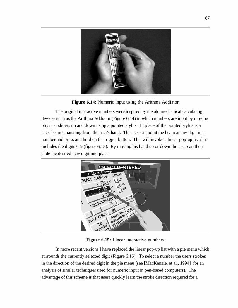
87
Figure 6.14: Numeric input using the Arithma Addiator.
The original interactive numbers were inspired by the old mechanical calculating
devices such as the Arithma Addiator (Figure 6.14) in which numbers are input by moving
physical sliders up and down using a pointed stylus. In place of the pointed stylus is a
laser beam emanating from the user's hand. The user can point the beam at any digit in a
number and press and hold on the trigger button. This will invoke a linear pop-up list that
includes the digits 0-9 (figure 6.15). By moving his hand up or down the user can then
slide the desired new digit into place.
Figure 6.15: Linear interactive numbers.
In more recent versions I have replaced the linear pop-up list with a pie menu which
surrounds the currently selected digit (Figure 6.16). To select a number the users strokes
in the direction of the desired digit in the pie menu (see [MacKenzie, et al., 1994] for an
analysis of similar techniques used for numeric input in pen-based computers). The
advantage of this scheme is that users quickly learn the stroke direction required for a

88
particular digit and as a result doesn't have to pay as close attention when inputting a
number. Another advantage is that the pie menu can be treated as an interactive dial. If the
user moves the cursor in a circle about the selected digit, the appropriate carry will be
propagated when the cursor crosses the zero point on the dial. This means the user can use
the interactive number to crank up (or down) the entire value, the selected digit controlling
the rate of change of the selected parameter.
Figure 6.16: Rotary interactive numbers.
If the user selects an empty space to the left of the number's current most-
significant digit he can change that space to any digit (1-9) and zeros will fill in all the
intermediate spaces. This allows him to quickly enter large values. If the user points at an
existing number, presses a modifier key, and then moves his hand left or right he copies
the currently selected digit left or right, clearing any numbers already there.
The user can also grab the decimal point and slide it left or right (increasing or
decreasing the number of digits to the right of the decimal point), and he can change the
sign of the current value at any time.
The advantages of the interactive numbers scheme is that it allows one to double up
input and output in the same region of the control panel instead of having a numerical
display and a separate input widget (such as a slider or a virtual keypad). Moreover, in
principle, interactive numbers are unbounded, though in practice they are limited by the
number of digits that can be displayed. Furthermore, the technique doesn't require the user
to learn how to use an unfamiliar input device such as a chord keyboard or have to struggle
with a virtual keypad that suffers from the lack of haptic feedback (touch typing without the
touch). Interactive numbers are, however, susceptible to noise in tracking data.

89
Techniques such as interactive numbers may be unnecessary if one has means for
reliable voice input. However there may be cases in which it is not possible or desirable to
use voice input (loud environmental conditions, difficulty talking all day, or simple user
preference). In such cases a manual technique for numeric input is required.
90
Chapter 7
Final Words
7.1 Conclusions
One of the fundamental advantages of working in a virtual world is that natural
forms of interaction such as reaching out to grab and manipulate an object, leaning forward
to get a closer view, and turning one's head to look at something, can be powerfully
enhanced in ways not possible in the real world. Simple and intuitive actions become
powerful and effective virtual-environment interaction techniques that minimize user work
such as scaled-world grab, head-butt zoom, and orbital mode.
The virtual world, however, is not without incidental difficulties. In a typical
virtual world a person's vision is poor, and the sense of touch is limited at best. He
communicates without voice and the written word, and interacts using whole-hand gestures
but not his fingers. He lacks physical surfaces on which he can ground himself to steady
his actions and on which he can rest to limit fatigue. These incidental difficulties
complicate interaction in a virtual world and limit the effectiveness of virtual-world
applications.
The goal of my research has been a better understanding of the strengths and
weaknesses of working in a virtual world. My interests lay in the development of intuitive
and effective virtual-environment interaction techniques that enhance natural forms of
interaction, exploit the benefits of working in a virtual world, and compensate for its
limitations.
In this dissertation, I proposed that one use proprioception to compensate for the
lack of haptic feedback in a virtual world. I presented three ways that a user can exploit
proprioception during virtual-environment interaction: by manipulating objects within his
natural working volume (direct manipulation), by storing objects at fixed locations relative
91
to his body (physical mnemonics), and by using his body sense to help recall actions used
to invoke commands or to communicate information (gestural actions).
To bring instantly within reach objects which lie outside of the user's reach, I
devised automatic scaling. Automatic scaling minimizes user work and enables direct
manipulation within a user's natural working volume.
I developed several novel virtual-environment interaction techniques based upon my
framework of body-relative interaction. Both formal user studies and informal user trials
have shown these techniques to be effective forms of interaction in a virtual world.
The virtual docking study confirmed the intuition that it is more effective to
manipulate an object that is co-located with one's hand (as is the case in scaled-world grab)
than it is to manipulate an object held at some offset. Subjects were able to align hand-held
docking cubes with target cubes significantly faster than they were able to align docking
cubes held at a fixed and variable offsets. The results of the experiment, however, did not
measure the effects of automatic scaling on the user's ability to manipulate objects.
The virtual widget interaction study demonstrated that subjects could take advantage
of proprioception when interacting with virtual widgets. In the absence of visual feedback,
they were able to return to a point on a widget held in their hand significantly more
accurately than they could to a similar point on a widget floating in space. This suggests
that proprioceptive cues can be used to augment visual feedback when interacting with
hand-held widgets.
Observations during informal user trials of the CHIMP system support and
complement the results of the formal user studies. Users have found body-relative
interaction to be intuitive and easy to use. They quickly adapt to techniques such scaled-
world grab, head-butt zoom, and over-the-shoulder deletion. Automatic scaling of the
world for both manipulation and locomotion is a powerful technique which enables users to
quickly and easily accomplish their goals. Though it has no real-world counterpart, it feels
natural and intuitive. Users manipulate distant objects with ease and are often surprised to
learn that scaling has taken place.
7.2 Contributions
The overall contribution of my work is an improved understanding of what it means
to work in a virtual world. The byproducts of this understanding are natural, intuitive, and
effective virtual-environment interaction techniques that minimize user work and thus
maximize user efficiency.

92
I consider the following specific items to be the significant contributions of this
research:
• A Framework for Virtual Environment Interaction. The development of a
framework for virtual environment interaction based upon proprioception.
• Automatic Scaling. The invention of automatic scaling as a technique for
bringing remote objects instantly within reach.
• Body-relative Interaction Techniques. The creation of several novel virtual-
environment interaction techniques based upon the framework of proprioception
for virtual-environment interaction.
• Direct Manipulation:• Scaled-world grab for manipulation• Scaled-world grab for locomotion
• Physical Mnemonics• Pull-down menus• Hand-held widgets
• Gestural Actions• Head-butt zoom• Two-handed flying• Over-the-shoulder deletion
• The virtual docking user study. A formal user study which compared the
manipulation of virtual objects co-located with one's hand and the manipulation
of virtual objects held at an offset.
• The virtual widget interaction study. A formal user study which contrasted
interaction with widgets held in the hand and interaction with widgets floating in
space.
• CHIMP. Integration of numerous body-relative interaction techniques into a
real-world system, the Chapel Hill Immersive Modeling Program.
• Interactive Numbers. The development of Interactive Numbers, a manual
technique for numeric input in a virtual world.
• Modeling System Review. A detailed review of the current state-of-the-art in
computer-aided modeling.

93
7.3 Future Work
Localized Haptic Feedback
Though proprioception greatly enhances virtual-environment interaction, precise
manipulation is still harder in virtual spaces than in real space. Several factors complicate
fine-grained manipulation.
First, the lack of physical work surfaces and haptic feedback makes the controlled
manipulation of virtual objects much more difficult. Users typically manipulate virtual
objects by holding their arms out without support. In the real world, a person generally
grounds the arm at the forearm, or elbow, or heel of hand to steady hand motions and to
reduce fatigue when performing precise manipulation.
Second, humans depend upon naturally occurring physical constraints to help
determine the motion of objects they are manipulating (sliding a chair along a floor, for
example). Whereas it is possible to implement virtual equivalents of physical constraints
[Bukowski and Sequin, 1995] , it is more difficult for the user to take advantage of these
constraints without haptic feedback. He can only see that the chair is on the floor, he can't
feel the contact, hear it, or sense the vibration as the chair slides.
Third, users in a virtual world must typically do without the fingertip control they
rely on for the fine-grained manipulation of objects in the real world. Though instrumented
gloves show promise for the fine-grained manipulation of objects [Kijima and Hirose,
1996] , their use has been primarily limited to the recognition of a few commands
associated with hand posture [Kessler, et al., 1995] .
I am interested in exploring the use of hand-held tablets as a means of giving users
a real surface on which they can work using haptic constraints (following the lead of
[Sachs, et al., 1991] and [Stoakley, et al., 1995] ). The tablet can be used as a two-
dimensional drawing surface (to define detailed two-dimensional shapes) or it can be used
as the input space for a two-dimensional menu (allowing users to interact precisely with
widgets and controls).
If the user interacts with the tablet using a hand-held stylus, he can take advantage
of the user's fingertip control precision. In addition the friction between tablet and stylus
and the grounding of the stylus against the tablet give the user better control.

94
To provide a larger work surface the tablet can be docked in a larger fixed physical
surface such as a lectern or a drafting table which can also provide grounding and support
during object manipulations (see related work in [Mapes and Moshell, 1995] ).
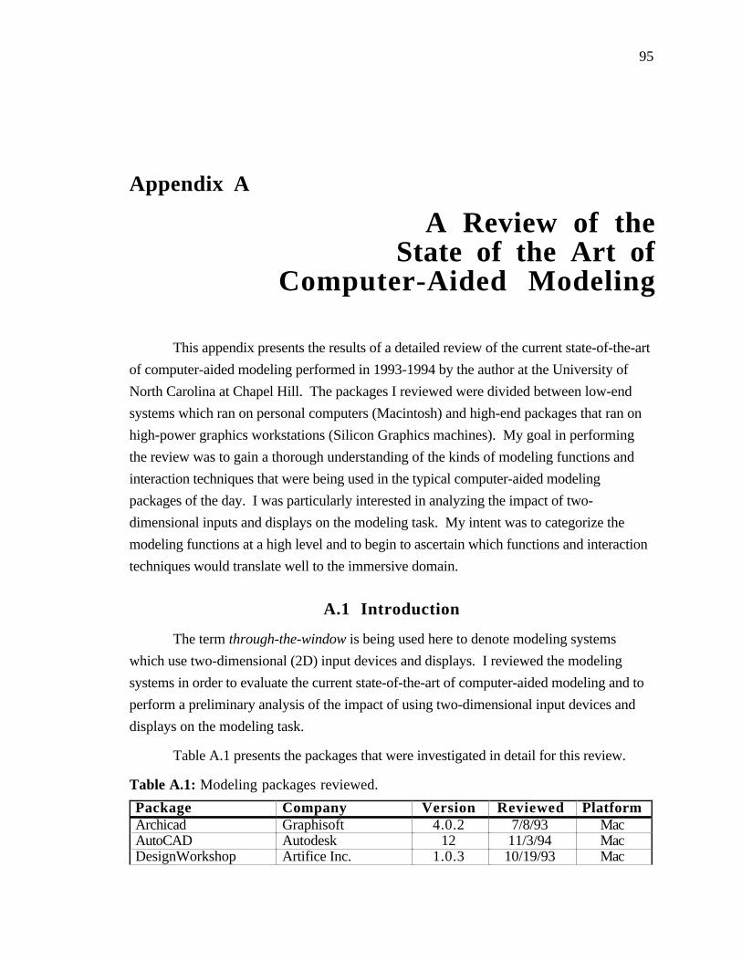
95
Appendix A
A Review of theState of the Art of
Computer-Aided Modeling
This appendix presents the results of a detailed review of the current state-of-the-art
of computer-aided modeling performed in 1993-1994 by the author at the University of
North Carolina at Chapel Hill. The packages I reviewed were divided between low-end
systems which ran on personal computers (Macintosh) and high-end packages that ran on
high-power graphics workstations (Silicon Graphics machines). My goal in performing
the review was to gain a thorough understanding of the kinds of modeling functions and
interaction techniques that were being used in the typical computer-aided modeling
packages of the day. I was particularly interested in analyzing the impact of two-
dimensional inputs and displays on the modeling task. My intent was to categorize the
modeling functions at a high level and to begin to ascertain which functions and interaction
techniques would translate well to the immersive domain.
A.1 Introduction
The term through-the-window is being used here to denote modeling systems
which use two-dimensional (2D) input devices and displays. I reviewed the modeling
systems in order to evaluate the current state-of-the-art of computer-aided modeling and to
perform a preliminary analysis of the impact of using two-dimensional input devices and
displays on the modeling task.
Table A.1 presents the packages that were investigated in detail for this review.
Table A.1: Modeling packages reviewed.
Package Company Version Reviewed PlatformArchicad Graphisoft 4.0.2 7/8/93 MacAutoCAD Autodesk 12 11/3/94 MacDesignWorkshop Artifice Inc. 1.0.3 10/19/93 Mac

96
Designer's WorkbenchCoryphaeus Software 2.1 10/26/94 SGIForm-Z Auto-Des-Sys 2.6.1 8/24/93 MacIGRIP Deneb Robotics 2.2.3 9/21/94 SGIMinicad+4 Graphsoft 4.0v3 9/24/93 MacMultiGen Software Systems 14.0 10/19/94 SGISculpt 3D Byte by Byte Corp. 2.06 7/21/93 MacUpfront Alias Research 2 10/8/93 MacWalkThrough Virtus Corporation 1.1.3 6/3/93 Mac
Section A.2 is a discussion of the modeling techniques and paradigms identified
during this review. Section A.3 is a detailed comparison of the capabilities of all the
modeling systems reviewed. Section A.4 introduces the modeling system reviews and
presented in Sections A.5-A.15 are the individual modeler reviews themselves
(highlighting the distinguishing characteristics of each system).
A.2 Modeling Techniques and Paradigms
Though the most apparent difference between modeling systems is the type and
extent of modeling primitives provided to construct three-dimensional shapes (see Section
A.3), modeling systems can also be classified according to the interaction techniques used
to perform the three-dimensional modeling task.
A.2.1 Input for a Three-Dimensional Task
One of the primary input tasks in the generation of three-dimensional shapes is the
specification of three-dimensional positions, orientations and extents. Several different
techniques are used to specify these parameters. These include:
1) Numeric input.
2) Relative input.
3) 2D interactive input.
A.2.1.1 Numeric Input.
Numeric input enables the specification of precise values by allowing the user to
input quantities directly using the numeric keys on the computer's keyboard. By using
numeric input, the user can specify the exact position, orientation and extents of an object.
Each component of a three-dimensional parameter is controlled separately.
A.2.1.2 Relative Input.
Relative input is the specification of parameters based upon the state of existing
objects. Arrow keys, for example, can be used to modify an object relative to its current

97
state (e.g. larger, smaller, move left, move right). Alternately, alignment commands can
by used to position an object relative to other objects within the modeling space (e.g. align
left sides, align tops).
A.2.1.3 2D Interactive Input.
Two-dimensional interactive input involves the use of input devices such as the
mouse and the data tablet to interactively specify modeling parameters. For the majority of
modeling systems, this is one of the primary means of controlling the modeling cursor (the
point in the three-dimensional modeling space at which all modeling actions occur). Using
a 2D input device the user may interact directly with the model or indirectly via control
panels (using interactive controls such as sliders and dials).
The use of a 2D input device necessitates some form of mapping between the
movements of the 2D input device and movements of the modeling cursor in the three-
dimensional modeling space. Two-dimensional input devices preclude the direct
specification of three-dimensional parameters; at least two separate inputs are required to
fully specify all three components. Though I observed many different variations of the
mapping of a three-dimensional task to a two-dimensional input device, most modelers fall
into two basic categories:
Working-Plane Plus Extrusion
In many cases the current elevation of the modeling cursor must be prespecified.
During subsequent modeling actions this component is held constant and movements of the
input device are mapped directly onto the remaining two components of the cursor position.
In many modeling systems this prespecified component is what is known as the current
working plane. All movements of the input device are mapped directly onto the current
working plane. The elevation of the current working plane remains fixed until it is reset
using some separate form of specification such as numeric input, the movement of a slider,
or through movements of the input device that are differentiated from normal device
movements by the simultaneous pressing of a modifier key (see for example
DesignWorkshop).
Similarly for extents, all movements of the input device are used to specify the
extents of an object in two dimensions only. The third dimension, or extrusion height,
must be specified separately, again using techniques such as numeric input, sliders, and
modified input-device motions.
In systems using working-plane-plus-extrusion input device mapping, objects are
created by drawing a two-dimensional profile in the current working plane that is then

98
extruded to the specified extrusion height. All objects are at the same elevation (the current
working plane) and have the same height (the extrusion height). To create an object at a
different elevation (a shelf four feet above the ground, for example), the user must reset the
working plane to the new desired elevation. To create an object with a different height, he
must reset the extrusion height.
Some systems, such as the Upfront program from Alias Research, allow the user to
quickly position the working plane relative to existing objects by snapping the working
plane to be coincident with any indicated object face. This makes it easy to quickly create a
vase on top of a table for example. It also makes it necessary, however, to create
construction surfaces, objects whose sole purpose is to assist in the construction process.
Thus to create a shelf four feet off the ground you would first create an object that is 4 feet
high, snap the working plane to the top of the object, and then create the shelf at that
height.
Arbitrary rotations are difficult to specify in a working-plane-plus extrusion system;
most rotations are generally limited to rotations about the normal of the current working
plane. More complex rotations often require the use of numeric input (via separate dialog
boxes) to be fully specified.
Orthogonal Input
As an alternative to the use of working planes, some systems allow the direct
specification of all three components of the current cursor position. In an orthogonal-input
system, the user is given three orthogonal views into the modeling space (see Section
A.2.2 below). Associated with each view is a 2D marker, which indicates the position of
the 3D modeling cursor relative to that view. The 3D modeling cursor can be directly
positioned at any three-dimensional coordinate in space (to perform some modeling action)
by specifying the position of the 2D marker in any pair of windows. This determines all
three coordinates of the 3D cursor with one coordinate specified redundantly in both
windows.
Rotations in an orthogonal-input system are typically about an axis perpendicular to
the currently active window.
A.2.2 Output of a Three-Dimensional Space
Modeling system output can be classified according to the three following
characteristics:
1) The format of the view provided into modeling space.

99
2) The visualization view: Is it separate from or integrated with the modeling view?
3) The visualization view: Is it static or interactive?
A.2.2.1 Format of the Modeling View.
One of the most important characteristics of a modeling system is the format of the
views provided into the modeling space (the space in which the user performs all modeling
actions). Several different types of views are available for the visualization of the three-
dimensional modeling space:
1) 2D Plan
2) Orthogonal
3) Arbitrary Viewpoint
2D Plan
This is a straightforward extension of two-dimensional drafting. In a 2D-plan
system, the user is presented a two-dimensional parallel projection (plan view) of the
modeling space. The projection is typically along one of the principal axes of the space
with the default view being an overhead view - similar to an architectural blueprint.
Examples of modeling systems of this type include: Archicad and Virtus WalkThrough.
Orthogonal
In an orthogonal-view system the user is given three orthogonal views into the
modeling space (see Sculpt 3D). Each view is typically a parallel projection along one of
the principal axes and can be thought of as the unfolded views into a cube surrounding the
modeling space (see Figure A.1). The main drawback of this type of system is the need to
integrate three orthogonal views into a mental picture of the three dimensional shape being
created. Sculpt 3D is an orthogonal-view system.

100
Figure A.1: Orthogonal-view system.
Arbitrary Viewpoint
In an arbitrary-viewpoint system the user is presented a two-dimensional projection
of the three-dimensional modeling space. The view is completely arbitrary and the user can
specify eye-point (center-of-projection) and focus-point (center-of-interest). AutoCAD,
DesignWorkshop, Designer’s Workbench, Form-Z, IGRIP, Minicad+4, MultiGen, and
Upfront are all arbitrary-viewpoint systems.
A.2.2.2 Three-Dimensional Visualization: Separate or Integrated
Most modeling systems provide some form of visualization view, a three-
dimensional rendering of the modeling space. Projections in the visualization view can be
parallel or perspective and the renderings can range from wire frame to fully textured and
shaded. The visualization view can either be separate from or integrated with the modeling
view.
2D-plan-view and orthogonal-view systems, for example, typically include a
separate visualization view (not essential, but it can be difficult to infer the shape of the
modeled objects using only the modeling views provided in these systems). In an
arbitrary-viewpoint system, on the other hand, the modeling view and the visualization
view are integrated into one.
Separation of the modeling view and visualization view limits the impact of
rendering costs on modeling interaction. A separate visualization view, on the other hand,
must be mentally integrated by the user with the modeling space.
A.2.2.3 Three-Dimensional Visualization: Static or Interactive

101
The three-dimensional visualizations of modeling space may either be static (in
which the user must specify a new eye-point and focus-point for each new view of the
model) or interactive (in which the user can interactively navigate through the model).
Virtus WalkThrough, for example, provides an interactive walkthrough, a separate
visualization window in which the user can move through the model in near real-time.
Interactive visualization helps to provide a better understanding of the shapes being created.
A.2.2.4 Complications of Two-Dimensional Output
The use of two-dimensional (non-stereoscopic) displays for output inherently
injects ambiguity in the interpretation of the displayed information [Gregory, 1973] , this
complicates the modeling task.
3D Perspective View
Figure A.2a: Perspective projection ambiguity.
In a perspective projection system, for example, equal lengths have different
projections depending upon their distance from the viewer. This complicates the
interpretation of the modeling space as shown in Figure A.2a. When viewed in the
perspective projection, the smaller cube appears to lie in the center of the face of the larger
cube. The three orthogonal views (Figure A.2b), however, show that this is not actually
the case.
Top View Front View Side View
Figure A.2b: Three orthogonal views of the object in Figure A.2a.

102
Though the cube position is presented unambiguously in the three orthogonal
views, interaction in these type of systems may be more complicated since the user must
correlate the position of a two-dimensional marker in multiple windows in order to
determine the three-dimensional position of the modeling cursor.
A.3 Modeling System Capability Comparison
Presented in Table A.2 is a detailed comparison of the capabilities of the modeling
systems reviewed. Note that only three-dimensional modeling capabilities are included in
this comparison; two-dimensional drafting and text layout tools are not reviewed. The
categories used for comparison include:
• 3D Object Generation. Techniques used to create three-dimensional objects.
• Derivative Object Generation. Advanced techniques used to create three-dimensional objects.
• Object Selection. Techniques used to select objects or groups of objects.
• Object Information Functions. Techniques used to determine information aboutselected objects and/or the modeling environment.
• Object Transformation. Techniques used to modify an object's shape andposition.
• Surface Attribute Control. Techniques used to specify object surfacecharacteristics (such as color and texture).
• View Manipulation. Techniques used to manipulate viewpoint in the modelingviews and visualization views.
• Cursor Controls. Techniques used to control the modeling cursor.
The cursor-controls section of Table A.2 is divided into three sub-sections: snaps,
constraints, and construction assists. Snaps completely define all three components of a
three-dimensional coordinate (in effect overriding the current modeling cursor position).
Constraints define only one or two components of the three-dimensional coordinate
(confining the cursor to a line or a plane). The user interactively specifies the remaining
components. Construction assists are temporary geometric objects used (in conjunction
with the snaps and constraints) for the placement of the cursor and model objects.

103
Table A.2: Modeling system capability comparison.
• • • • • • • • • • •• • • • • • • • • • •• • • • • • • • • • •• • • • • • • • • • •• • • • • • • • • • •• • • • • • • • • • •• • • • • • • • • • •• • • • • • • • • • •• • • • • • • • • • •• • • • • • • • • • •• • • • • • • • • • •• • • • • • • • • • •• • • • • • • • • • •• • • • • • • • • • •• • • • • • • • • • •• • • • • • • • • • •
• • • • • • • • • • •• • • • • • • • • • •• • • • • • • • • • •• • • • • • • • • • •• • • • • • • • • • •
• • • • • • • • • • •• • • • • • • • • • •• • • • • • • • • • •• • • • • • • • • • •
• • • • • • • • • • •• • • • • • • • • • •• • • • • • • • • • •
Object Generationvertexblock
spherecone
regular prismirregular prism
3D polygonpolygon strip
terrain/contour surfacecurved surface
wallroofslab
rectangular openingirregular opening
library object
Derivative Object Generationextrude
surface of revolutionloft
sweep along pathlevel of detail generation
Object Selectionpointer
marqueeby name/hierarchy
by type
Object Information Functionsedge/radius dimensions
area calculationmaterials database
Arc
hica
d
Aut
oC
AD
Des
igne
r's W
ork
ben
ch
Des
ignW
orks
hop
For
m-Z
IGR
IP
Min
ica
d+4
Mul
tiGen
Scu
lpt
3D
Upf
ront
Wa
lkth
roug
h

104
Table A.2 (cont'd): Modeling System Comparison
• • • • • • • • • • •• • • • • • • • • • •• • • • • • • • • • •• • • • • • • • • • •• • • • • • • • • • •• • • • • • • • • • •• • • • • • • • • • •• • • • • • • • • • •• • • • • • • • • • •• • • • • • • • • • •• • • • • • • • • • •• • • • • • • • • • •• • • • • • • • • • •• • • • • • • • • • •• • • • • • • • • • •• • • • • • • • • • •• • • • • • • • • • •• • • • • • • • • • •
• • • • • • • • • • •• • • • • • • • • • •• • • • • • • • • • •• • • • • • • • • • •
• • • • • • • • • • •• • • • • • • • • • •• • • • • • • • • • •• • • • • • • • • • •• • • • • • • • • • •• • • • • • • • • • •• • • • • • • • • • •• • • • • • • • • • •
Object Transformationmoverotatescale
reshapeduplicate
duplicate linearduplicate circular
mirrortrin/slice
cut to gridfilet
projectplantbend
CSG operatorssurface intersectionmagnet attract/repel
set/modify convergence
Surface Attribute Controlcolor sample
color settransparency control
texture control
View Manipulationpan
zoomset eye point
set focus pointrotate about eye point
rotate about focus pointset field-of-view
interactive walkthrough
Arc
hic
ad
Aut
oCA
D
Des
igne
r's W
orkb
ench
Des
ignW
orks
hop
For
m-Z
IGR
IP
Min
icad
+4
Mul
tiGen
Scu
lpt 3
D
Upf
ron
t
Wal
kth
roug
h
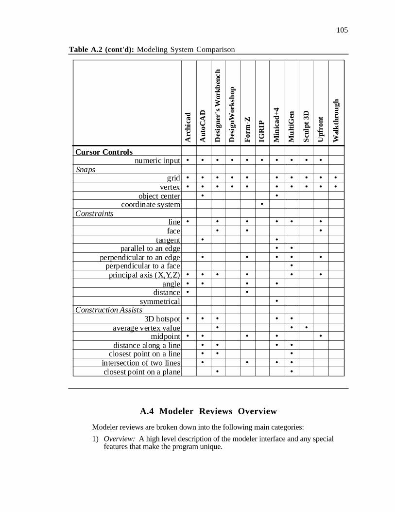
105
Table A.2 (cont'd): Modeling System Comparison
• • • • • • • • • • •
• • • • • • • • • • •• • • • • • • • • • •• • • • • • • • • • •• • • • • • • • • • •
• • • • • • • • • • •• • • • • • • • • • •• • • • • • • • • • •• • • • • • • • • • •• • • • • • • • • • •• • • • • • • • • • •• • • • • • • • • • •• • • • • • • • • • •• • • • • • • • • • •• • • • • • • • • • •
• • • • • • • • • • •• • • • • • • • • • •• • • • • • • • • • •• • • • • • • • • • •• • • • • • • • • • •• • • • • • • • • • •• • • • • • • • • • •
Cursor Controlsnumeric input
Snapsgrid
vertexobject center
coordinate systemConstraints
lineface
tangentparallel to an edge
perpendicular to an edgeperpendicular to a faceprincipal axis (X,Y,Z)
angledistance
symmetricalConstruction Assists
3D hotspotaverage vertex value
midpointdistance along a line
closest point on a lineintersection of two linesclosest point on a plane
Arc
hica
d
Aut
oCA
D
Des
igne
r's W
orkb
ench
Des
ignW
orks
hop
For
m-Z
IGR
IP
Min
icad
+4
Mu
ltiG
en
Scu
lpt 3
D
Upf
ront
Wal
kthr
ough
A.4 Modeler Reviews Overview
Modeler reviews are broken down into the following main categories:
1) Overview: A high level description of the modeler interface and any specialfeatures that make the program unique.

106
2) Model Creation: A description of the techniques used in creating model objects.Note that the focus is on three-dimensional rather than two-dimensionalmodeling techniques.
3) Model Modification: A description of the functions provided by the programfor altering existing model objects (move, rotate, scale).
4) Model Interaction/Visualization: The types of features provided for interactionwith the modeling and visualization views.
5) Manual: A description of the quality, completeness, and usefulness of themanuals/tutorials provided with each package.
6) General Impressions: Observations/opinions about the utility of each packageas a three-dimensional modeling tool. Descriptions of outstanding/usefulfeatures and of limitations/problems encountered.
Table A.3 is a summary of the input and output paradigms (defined in section A.2)
used by each modeling system.
Table A.3: Modeling system paradigms.
Modeler Input Technique Output Format 3D VisualizationArchicad Working Plane 2D Plan Separate, StaticAutoCAD Working Plane Arbitrary Integrated, InteractiveDesigner's Workbench Working Plane Arbitrary Integrated, InteractiveDesignWorkshop Working Plane Arbitrary Integrated, InteractiveForm-Z Working Plane Arbitrary Integrated, InteractiveIGRIP Numeric Arbitrary Integrated, InteractiveMinicad+4 Working Plane Arbitrary Integrated, InteractiveMultiGen Working Plane Arbitrary Integrated, InteractiveSculpt 3D Orthogonal Orthogonal Separate, StaticUpfront Working Plane Arbitrary Integrated, InteractiveWalkThrough Working Plane 2D Plan Separate, Interactive

Archicad version 4.0.2, reviewed 7/8/93
107
A.5 Archicad
A.5.1 Overview
Input technique: Working-plane plus extrusion.Output format: 2D Plan view.3D Visualization: Separate, static.
The main components of the Archicad interface include:
• Archicad plan worksheet. 2D plan view used to interact with the model.
• 3D view. The visualization view used to view a three-dimensional projection ofthe current model.
• Menu bar. Provides access to the various commands and dialog boxes used tointeract with Archicad.
• Toolbox. The graphical toolbox used to switch between the various modes ofinteraction and modeling tools.
• Control box. Used to turn snap-to-grid on and off and control placement ofwalls relative to the specified lines.
• Coordinate box. Used for direct numerical input of positions, angles anddistances (can be specified in either relative or absolute coordinates).
Figure A.3 presents a snapshot of the Archicad interface.
Figure A.3: Archicad interface.

Archicad version 4.0.2, reviewed 7/8/93
108
Most tools have a related dialog box which can be used to adjust the default
behavior of each tool. Included in each dialog box are settings such as heights of walls,
and widths of doors. Object settings can also be copied from object to object (e.g. to make
two doors look identical).
Archicad is a three-dimensional modeler which has been optimized for architectural
design. Special tools are included for creating walls, roofs, doors and windows. Also
included is a large library (with third party libraries also available) of default three-
dimensional objects (such as cabinets, tables, and chairs) that can be used to populate the
model. The library also includes sample window and door types which can be used to fill
door and window openings. Each of these library objects can be placed with a click of the
mouse button and are parametric so that you can adjust characteristics such as the width of
a door, or the height of a window above the floor. New library objects can be created
using GDL, Archicad's graphics description language.
A.5.2 Model Creation
Using Archicad's specialized set of architectural building tools, a user can quickly
create a fairly complex building shell, with doors and windows cut out of the walls and a
fairly complicated roof. Sample doors and windows can be added with just a few
additional clicks of the mouse button.
Object positions and sizes can be specified interactively or directly using the
numerical input feature. The multiple modes of numeric input (combinations of absolute
and relative coordinates) are somewhat awkward to use but it is easy to transition between
mouse mode and numeric input (it is not necessary to move the mouse cursor into a
numeric input window to switch between the two modes).
To aid in model creation, Archicad provides the standard aids such as snap to
vertex, and snap to grid. Archicad also provides the capability of specifying a hot spot
which can act as an additional snap location. Two grids are provided: the standard snap
grid and a more complicated construction grid (which is used to specify both the spacing
and width of regularly placed objects).
A.5.3 Model Modification
Model components can be moved, rotated and resized. Since most objects (except
the roof segments) are assumed to be perpendicular to the floor, Archicad does not include
a means of specifying arbitrary 3D orientation. A diagonal coal chute, for example, would

Archicad version 4.0.2, reviewed 7/8/93
109
be difficult to model. Instead, objects are rotated around a vertical axis perpendicular to the
floor. Objects are repositioned using the drag feature. Archicad also includes a drag-with-
repeat and a rotate-with-repeat feature to create regular structures (such as a colonnade)
where objects have regular spacing or rotation angles.
A.5.4 Model Interaction/Visualization
The user can pan, zoom and scroll in the modeling view.
Archicad uses special cursor shapes to convey information to the user about the
type of object being pointed at by the mouse. These are used to help in the selection of
objects such as vertices, wall edges, and doors.
Archicad utilizes static three-dimensional visualizations which are displayed in a
separate 3D visualization view. Using the view control dialog box, the user can specify
parameters such as view direction, observer location, field-of-view (where applicable), and
lighting direction. There are several different projection options: top view, elevation,
isometric, oblique, plan oblique, axonometric, perspective. The user can also specify a
path for generating a walkthrough of the model. The quality of the images can be quite
high, but Archicad suffers from the lack of an interactive visualization. This hampers the
interactive design process since the user must wait to see the results of a design change.
The 3D view by default only renders the items currently selected on the plan
worksheet. This is useful for rendering a subpart of a complex model but it is easy to
forget to deselect the last item you were working on. It can be frustrating to end up with a
rendering of only a portion of your model when you intended to render the entire thing.
A.5.5 Manual
Archicad provides a complete set of reference manuals that describe each function in
detail. Though comprehensive, the manuals suffer from the lack of an introductory
tutorial. Important details on how to use the tools are often buried in the tool descriptions.
To get a good understanding of how to use Archicad you would have to read all the
manuals in detail.
Archicad also includes a hypercard tutorial stack, however it adds little beyond what
is found in the reference manuals.

Archicad version 4.0.2, reviewed 7/8/93
110
A.5.6 Comments/Impressions
Archicad is a well thought-out product for exploring the preliminary stages of
architectural design (i.e. the basic shape and spaces of a building). I was very impressed
at how easy it was to build the basic shell of a house. Within a half an hour I could place
all the walls in a building and specify holes for the doors and windows. If you require a
tool for preliminary design exploration, Archicad is an excellent choice.
Archicad is not as effective when it comes time to add additional detail such as
specific doors and windows, or furniture to a model ( to add realism or to lend a sense of
scale). Archicad particularly suffers from the lack of an interactive 3D visualization. This
makes it difficult to explore design alternatives such as the exact placement of a window.
Archicad is also not well suited for the creation of arbitrary three-dimensional
shapes. The 3D object creation tools are optimized for doors and windows and are not
general modeling tools. Objects can be created from scratch using the Graphics Description
Language (GDL) and saved as library items, but GDL is more easily used for making
modifications to existing objects (changing an existing window for example). It would be
difficult to use GDL for complex modeling tasks.
Archicad's plan notes and materials computation options are useful features. The
plan notes are used to attach general notes and the material computation keeps a running
estimate on the amounts of materials required for the specified model. There is a large
variety of material types (such as brick, concrete, and wood) to choose from for each
component of the model.

Autocad version 12, reviewed 11/3/94
111
A.6 AutoCAD
A.6.1 Overview
Input technique: Numeric input, Working-plane plus extrusion.Output format: Arbitrary viewpoint.3D Visualization: Integrated, Interactive.
The main components of the AutoCAD interface include:
• Command line. Text window used to enter commands from the keyboard andto display prompts and messages.
• Graphics area. Graphics window used for interactive editing and modeldisplay.
• Menu bar. Pull-down menus which provide access to the various commandsand dialog boxes used in AutoCAD.
• Screen menu. Text based set of menus and submenus used for interaction withthe AutoCAD commands.
• Icon menus. Iconic tear-off menus used for object creation, modification anddimensioning commands.
• Status line. Text line displaying current information about the model (such asthe active layer and cursor coordinates)
Figure A.4 presents a snapshot of the AutoCAD interface.
Figure A.4: AutoCAD interface.
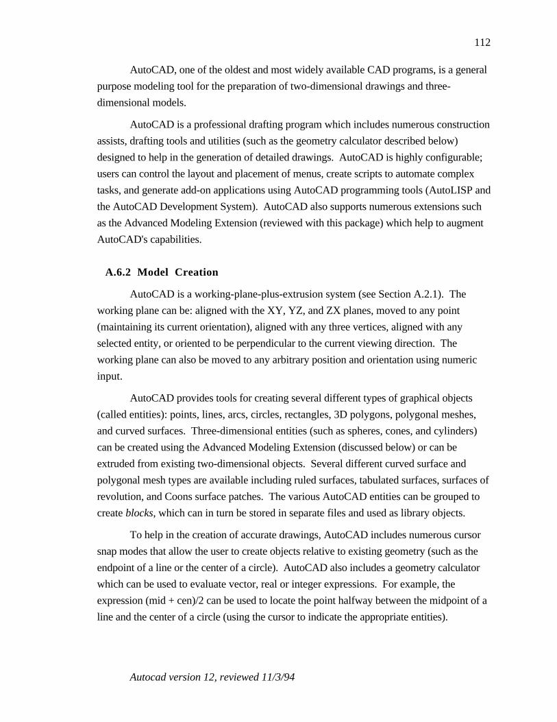
Autocad version 12, reviewed 11/3/94
112
AutoCAD, one of the oldest and most widely available CAD programs, is a general
purpose modeling tool for the preparation of two-dimensional drawings and three-
dimensional models.
AutoCAD is a professional drafting program which includes numerous construction
assists, drafting tools and utilities (such as the geometry calculator described below)
designed to help in the generation of detailed drawings. AutoCAD is highly configurable;
users can control the layout and placement of menus, create scripts to automate complex
tasks, and generate add-on applications using AutoCAD programming tools (AutoLISP and
the AutoCAD Development System). AutoCAD also supports numerous extensions such
as the Advanced Modeling Extension (reviewed with this package) which help to augment
AutoCAD's capabilities.
A.6.2 Model Creation
AutoCAD is a working-plane-plus-extrusion system (see Section A.2.1). The
working plane can be: aligned with the XY, YZ, and ZX planes, moved to any point
(maintaining its current orientation), aligned with any three vertices, aligned with any
selected entity, or oriented to be perpendicular to the current viewing direction. The
working plane can also be moved to any arbitrary position and orientation using numeric
input.
AutoCAD provides tools for creating several different types of graphical objects
(called entities): points, lines, arcs, circles, rectangles, 3D polygons, polygonal meshes,
and curved surfaces. Three-dimensional entities (such as spheres, cones, and cylinders)
can be created using the Advanced Modeling Extension (discussed below) or can be
extruded from existing two-dimensional objects. Several different curved surface and
polygonal mesh types are available including ruled surfaces, tabulated surfaces, surfaces of
revolution, and Coons surface patches. The various AutoCAD entities can be grouped to
create blocks, which can in turn be stored in separate files and used as library objects.
To help in the creation of accurate drawings, AutoCAD includes numerous cursor
snap modes that allow the user to create objects relative to existing geometry (such as the
endpoint of a line or the center of a circle). AutoCAD also includes a geometry calculator
which can be used to evaluate vector, real or integer expressions. For example, the
expression (mid + cen)/2 can be used to locate the point halfway between the midpoint of a
line and the center of a circle (using the cursor to indicate the appropriate entities).

Autocad version 12, reviewed 11/3/94
113
AutoCAD is heavily biased toward numerical input. Coordinates can be specified
using absolute or relative values, can be specified relative to world or user defined
coordinate systems, and can be given in cartesian, polar (2D), spherical (3D), and
cylindrical formats. Filters can be used to specify coordinate components separately (for
example setting the X coordinate of a point interactively with the mouse and the Y and Z
components using numeric input).
AutoCAD includes extensive dimensioning capability useful in the generation of
presentation drawings. AutoCAD will determine linear, radial, angular, and ordinate
(distance from User Coordinate System origin) dimensions of selected entities.
AutoCAD includes an isometric drawing mode for creating two-dimensional
isometric drawings. Though useful, it is less flexible than the isometric viewing modes
provided by many other applications.
The default AutoCAD environment can be augmented with several extension
packages such as the Advanced Modeling Extension (AME) and the AutoCAD SQL
Extension (ASE). The AME is a constructive solid geometry package which enables you to
perform boolean operations on two and three-dimensional entities and includes many
analysis functions for determining properties of a solid such as the mass, centroid and
moments of inertia. The ASE makes it possible to link your AutoCAD drawings with
external database management systems (such as dBASE, Oracle, or Paradox).
AutoCAD also provides several different programming tools: Scripts (a text-based
scripting language), AutoLISP (an implementation of the LISP programming language) and
ADS the AutoCAD Development System (a C-language programming environment).
These allow the user to create macro programs and functions to perform complex tasks
which can be executed at the AutoCAD command prompt.
A.6.3 Model Modification
Objects can be positioned, oriented, scaled, mirrored and duplicated. AutoCAD
includes circular and rectangular array commands which enable the creation of repeating
structures. Two-dimensional entities can be extruded into three-dimensions by modifying
their thickness. An adjustable taper can also be specified for solids created using the AME.
A grips mode is included which allows you to select objects and modify them directly (i.e.
move or rotate) using the mouse.
AutoCAD includes functions for editing polygonal meshes and curved surface
entities (including functions for fitting smooth surfaces to polygonal meshes).
Autocad version 12, reviewed 11/3/94
114
A.6.4 Model Interaction/Visualization
The user can pan and zoom on the model and can specify camera location and
center-of-focus. To help in the visualization of complex models, AutoCAD enables a user
to hide selected layers of model (this also enhances rendering performance). AutoCAD
models are typically presented as wireframe renderings, though shaded versions of the
model can be generated. AutoCAD does not have an interactive visualization mode.
A.6.5 Manual
AutoCAD has extensive documentation (13 lbs worth) including a user's guide,
command reference, installation guide and several programming guides. Also included is a
detailed tutorial which introduces the user to most of the AutoCAD commands. The
manuals are well written and the step-by-step instructions in the tutorial are easy to follow.
The main drawback of the manuals is that they concentrate on the command line interface of
AutoCAD (which is consistent across the many platforms on which AutoCAD is
supported). It can be difficult to find the menu or icon command for your specific platform
which corresponds to the command line function discussed in the manual.
A.6.6 Comments/Impressions
Key advantages of AutoCAD include the highly customizable interface, the various
analysis tools (for the calculation of areas, mass properties, geometric calculations, etc.),
the ability to extend the AutoCAD application with Autodesk or third party extensions and
the ability to enhance the AutoCAD environment with command scripts, AutoLISP and
ADS applications (the programming languages available with AutoCAD).
The disadvantages of AutoCAD are closely related to this wealth of options and
flexibility. The AutoCAD interface is complex and somewhat cumbersome to use. There
are many different menu types (some redundant), many different ways to do the same thing
and an overall feeling of a graphical user interface that was tacked on top of a command line
application. Models can be created interactively in the graphics window, but AutoCAD is
heavily biased towards keyboard input (as is reflected in its manuals). It is typically faster
to use the AutoCAD commands than it is to go through the menu interface.

Design Workshop version 1.0.3, reviewed 10/19/93
115
A.7 DesignWorkshop
A.7.1 Overview
Input technique: Working-plane plus extrusion.Output format: Arbitrary viewpoint.3D Visualization: Integrated, interactive.
The main components of the DesignWorkshop interface include:
• Modeling toolbox. The graphical toolbox used to switch between the variousmodes of interaction and modeling tools.
• Modeling window. Arbitrary viewpoint of modeling space. Used to interactwith the model.
• Location bar. Dialog box used to display information about the current cursorlocation.
• Object Info. Dialog box displaying information about the currently selectedobject.
Figure A.5 presents a snapshot of the DesignWorkshop interface.
Figure A.5: DesignWorkshop interface.
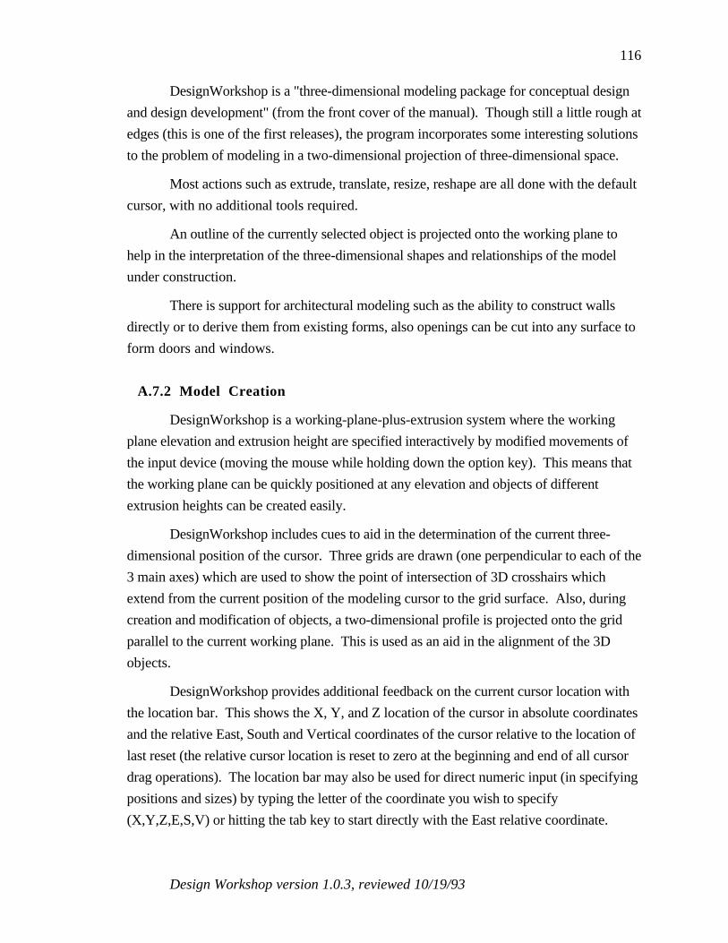
Design Workshop version 1.0.3, reviewed 10/19/93
116
DesignWorkshop is a "three-dimensional modeling package for conceptual design
and design development" (from the front cover of the manual). Though still a little rough at
edges (this is one of the first releases), the program incorporates some interesting solutions
to the problem of modeling in a two-dimensional projection of three-dimensional space.
Most actions such as extrude, translate, resize, reshape are all done with the default
cursor, with no additional tools required.
An outline of the currently selected object is projected onto the working plane to
help in the interpretation of the three-dimensional shapes and relationships of the model
under construction.
There is support for architectural modeling such as the ability to construct walls
directly or to derive them from existing forms, also openings can be cut into any surface to
form doors and windows.
A.7.2 Model Creation
DesignWorkshop is a working-plane-plus-extrusion system where the working
plane elevation and extrusion height are specified interactively by modified movements of
the input device (moving the mouse while holding down the option key). This means that
the working plane can be quickly positioned at any elevation and objects of different
extrusion heights can be created easily.
DesignWorkshop includes cues to aid in the determination of the current three-
dimensional position of the cursor. Three grids are drawn (one perpendicular to each of the
3 main axes) which are used to show the point of intersection of 3D crosshairs which
extend from the current position of the modeling cursor to the grid surface. Also, during
creation and modification of objects, a two-dimensional profile is projected onto the grid
parallel to the current working plane. This is used as an aid in the alignment of the 3D
objects.
DesignWorkshop provides additional feedback on the current cursor location with
the location bar. This shows the X, Y, and Z location of the cursor in absolute coordinates
and the relative East, South and Vertical coordinates of the cursor relative to the location of
last reset (the relative cursor location is reset to zero at the beginning and end of all cursor
drag operations). The location bar may also be used for direct numeric input (in specifying
positions and sizes) by typing the letter of the coordinate you wish to specify
(X,Y,Z,E,S,V) or hitting the tab key to start directly with the East relative coordinate.

Design Workshop version 1.0.3, reviewed 10/19/93
117
To aid in the direct creation of architectural shapes, DesignWorkshop includes a
block tool (for creating building masses to show the shape of a building, for example), a
poly-wall tool (for creating walls that define the inner spaces of a building), and tools to cut
openings in walls (for doors and windows).
A.7.3 Model Modification
All objects can be translated, rotated, reshaped and scaled. Many operations
(extrusion, translation, resizing and reshaping) are done with the default cursor. Rotation
of objects is accomplished by selecting the special rotation tool. Objects are rotated around
either their center or an edge depending upon where the object is grabbed. The trim
operator slices objects in two. The slice is perpendicular to a line drawn across one of the
object faces. A faces mode is included which allows you to manipulate individual faces of
blocks. Duplicate-linear and duplicate-circular are two menu items which allow you to
create repeating arrays of objects. By selecting a special dialog box item (miter edges) the
duplicate-circular becomes, in effect, an object of revolution tool.
A special Object Info floating palette is included which displays information about
the currently selected object. The Object Info palette can also be used to modify the
characteristics of the selected object by typing into the appropriate field. Characteristics
which can be modified include: position, orientation and extents.
A.7.4 Model Interaction/Visualization
DesignWorkshop has an integrated, interactive visualization view, all model
interaction is done in a three-dimensional perspective view. Design workshop includes the
standard ability to pan and zoom the current working view.
Two main tools, the Eye and Look tool are provided for changing the three-
dimensional view into the modeling world. The eye tool is used to move the current eye-
point around the center-of-interest. By pressing the option key the eye-point can be moved
in and out along the view vector. The look tool is used to move the center-of-interest
around in model space. The center-of-interest can be quickly set to the center of the model
(by double clicking on the look tool) or to any specific three-dimensional location by using
the standard DesignWorkshop cursor positioning methods.
Shadows can be generated to aid in the understanding of the three-dimensional
relationships between objects. A sun position can be chosen by selecting a latitude and a
time and date. QuickTime Sun study movies can be generated.
Design Workshop version 1.0.3, reviewed 10/19/93
118
A.7.5 Manual
DesignWorkshop includes a fairly brief manual and a quick reference guide. The
manual includes a quick start tutorial which explains the basics of using DesignWorkshop
and more detailed DesignWorkshop techniques section (covering site modeling, roofs,
surfaces of revolution, walls and stairs). DesignWorkshop can be learned fairly quickly,
due to its simple interface.
A.7.6 Comments/Impressions
DesignWorkshop shares the advantages and disadvantages common to all the
modelers that allow you to work directly in a 3D perspective view (see Section A.2.2).
DesignWorkshop does include several aids to assist in the proper placement of the
cursor. This includes: 3D crosshairs which extend to and intersect with 3 orthogonal
modeling grids, shadows that show the relationships of models in the working space, and
DesignWorkshop's Space-Jump, a method of instantaneously moving the cursor to the
three-dimensional position of any vertex in the model (the desired vertex is selected by
placing the image of the cursor over the image of the vertex and then tapping the space bar).
The ability to move the modeling cursor in all three directions makes it easier to
create objects at different elevations and with different extrusion heights than in systems
where the working plane and extrusion height are manipulated separately.
The main problem with DesignWorkshop at this time is the fact that it is such an
early release. This is quite evident in the number of features which are not completely
implemented and the number of bugs encountered during program execution. This leads to
an overall impression of the program as still being somewhat rough around the edges.

Designer’s Workbench version 2.1, reviewed 10/26/94
119
A.8 Designer's Workbench
A.8.1 Overview
Input technique: Working-plane plus extrusion.Output format: Arbitrary viewpoint.3D Visualization: Integrated, Interactive.
The main components of the Designer's Workbench (DWB) interface include:
• Database window. The window used to display and edit information in a singledatabase file. The database window can display an arbitrary viewpoint ofmodeling space or a hierarchical representation of the model. The graphicsview can be split to include three orthogonal views of the modeling space.
• Menu bar. Provides access to the various commands and dialog boxes used tointeract with Designer's Workbench.
• Icon Menus. The graphical toolbox used to switch between the various modesof interaction and modeling tools.
• Coordinate Window. Used for direct numerical input of positions, and extents(can be specified in either relative or absolute coordinates).
Figure A.6 presents a snapshot of the DWB interface
.
Figure A.6: Designer's Workbench interface.

Designer’s Workbench version 2.1, reviewed 10/26/94
120
Designer's Workbench is a three-dimensional modeler which runs on a Silicon
Graphics workstation. Notable features in Designer's Workbench include:
• The hierarchy view, a graphical representation of the model's hierarchical structure
(showing all parent-child relationships) which greatly simplifies interaction with
complex models. The hierarchy view can be used to quickly select portions of the
model with a single mouse click.
• Construction vertices: temporary vertices which can be used to help in the construction
and positioning of objects.
In addition to general-purpose modeling tools, DWB incorporates features useful in
the generation of flight simulator databases. Links, for example, are used to specify the
relationship between geometry and state variables making it possible to create animated
cockpit displays that are driven by dynamic data (such as simulated airspeed).
A.8.2 Model Creation
Designer's Workbench is a working-plane-plus-extrusion system (see Section
A.2.1). The working plane can be: aligned with the XY, YZ, and ZX planes, moved to
any vertex (maintaining its current orientation), aligned with any object face, or aligned
with any three vertices. The working plane can be moved to any arbitrary position and
orientation using numeric input and the working plane offset (translation along the normal
of the working plane) can also be set interactively using the mouse.
Designer's Workbench provides tools for the creation of irregular and regular
polygons, rectangles, spheres, cylinders, cones and strips (fixed width polygons along a
path which can be used for roads). Polygons may also be created from B-spline
construction curves (see below) using a B-spline to Poly tool. All objects are created
interactively (using the mouse) or with numeric input (to specify absolute or relative
positions of vertices). Two-dimensional faces can be extruded into three-dimensional
objects using the extrude tool. Unlike vertex positions, extrusion heights must be specified
in a separate numeric input window and can not be set interactively using the mouse in the
graphics window. Designer's Workbench also includes advanced tools for the creation of
surfaces of revolution and lofted objects (objects defined by a sequence of two-dimensional
profiles).
Designer's Workbench includes several types of construction assists. A rectangular
grid can be used during construction to constrain the cursor position to regular, adjustable
spacings. Grid spacing can be specified using numeric input or set interactively using the
Designer’s Workbench version 2.1, reviewed 10/26/94
121
mouse. The cursor can also be snapped to any vertex, edge or face using special modifier
keys. Construction vertices can be created: along a B-spline curve, at the midpoint of
selected vertices, at even intervals along a line, at the point on a plane or a line closest to a
selected vertex and at the intersection of any plane and line.
All objects created in Designer's Workbench are inserted into an object hierarchy
which encapsulates the relationship between objects, groups of objects, faces, edges and
vertices. The user can view a graphical representation of the hierarchy in which he can
reorganize structural relationships using commands or interactive drag and drop editing to
detach and attach nodes in the hierarchy.
A.8.3 Model Modification
The user can interact with the model at many different topological levels; the user
can select and manipulate vertices, edges, faces, objects, and groups of objects.
Designer's Workbench includes several techniques for object selection which
facilitate interaction with complex models. Objects can be selected: in the graphics view,
using the object hierarchy, and by attribute.
When selecting objects in the graphics view, the user controls the scope of selection
(verticies, edges, faces, objects, and group of objects) through the topological level. The
user can choose between overlapping objects by cycling through a pick hit list, a list of all
elements within the vicinity of the cursor during the last selection. The Imploded View
command is used to aid in the selection of coincident vertices by causing faces to
temporarily contract about their center (separating coincident vertices).
The hierarchical view is useful when the model has grown complex enough that it is
difficult to select objects in the graphics view. Related segments of a model can be selected
using a single mouse click by selecting the appropriate node in the object hierarchy. An
excellent feature of Designer's Workbench is the inclusion of a thumbnail sketch in the
hierarchical view which displays the currently selected item. This avoids the need to toggle
between the hierarchy view and graphics view to verify object selection.
Finally, objects can be selected by attributes (such as color) or boolean
combinations of attributes.
Objects can be positioned, oriented and scaled. Designer's Workbench includes
several more advanced scaling modes including scale to size and scale along a vector.

Designer’s Workbench version 2.1, reviewed 10/26/94
122
A.8.4 Model Interaction/Visualization
One of the key advantages of Designer's Workbench is that it runs on a Silicon
Graphics workstation; this provides the graphics power required for smooth interaction
with complex models. Designer's Workbench is an integrated system, the modeling view
and visualization view are combined into one.
Designer's Workbench allows you to rotate the viewpoint about the model, zoom in
and out and pan your view. Up to ten different eyepoint locations can be saved and then
immediately recalled using eyepoint controls. The fit command centers the selected
database items in the window and moves the eyepoint so the selected items fill the window.
Using the isolate command will result in the selected items appearing alone in the graphics
window. Several isolate views can be defined and DWB automatically generates buttons
that can be used to quickly switch between the available views.
A.8.5 Manual
The DWB documentation is divided into a user's manual, which gives an overview
of the basic operation of Designer's Workbench, and a reference manual, a detailed
description of all DWB features. Though these are fairly well written, it is sometimes
difficult to find a description of a specific function. For example the eyepoint controls
discussed above are described in both the user's manual and the reference manual but the
reference manual lacks an appropriate index entry to help locate the description. Designer's
Workbench includes a context sensitive help mode which displays information about each
icon and menu command.
A.8.6 Comments/Impressions
Designer's Workbench is a good choice for the generation of complex models.
Running on a Silicon Graphics workstation, the user has the necessary power to work with
large complex models. The ability to interact with a hierarchical representation of the model
is invaluable in the selection and isolation of segments in complex models. Learning to use
to hierarchy effectively, however, does take some time.
The disadvantages of Designer's Workbench include a complex interface, a limited
set of modeling primitives (no curved surface and constructive solid geometry operators),
and a high price.

Form-Z version 2.6.1, reviewed 8/24/93
123
A.9 Form-Z
A.9.1 Overview
Input technique: Working-plane plus extrusion.Output format: 2D plan & Arbitrary viewpoint.3D Visualization: Integrated, interactive.
The main components of the Form-Z interface include:
• Modeling/Drafting window. 2D plan view or 3D arbitrary viewpoint used tointeract with the model.
• Menu Bar. Provides access to the various commands and dialog boxes used tointeract with Form-Z
• Modeling Tools toolbox. The graphical toolbox used to switch between thevarious modes of interaction and modeling tools.
• Window Tools toolbox. Tools to control working plane orientation, cursormovement (including snaps), viewpoint on modeling space and error andmemory information.
Figure A.7 presents a snapshot of the Form-Z interface.
Figure A.7: Form-Z interface.

Form-Z version 2.6.1, reviewed 8/24/93
124
Form-Z is a general purpose solid and surface modeler. Surface objects are simple
open and closed lines and meshed surfaces. Solid objects are three-dimensional shapes
enclosing volumes (cubes, spheres, cylinders etc.). In-between these two are surface
solids which are two sided surfaces that are completely enclosed but contain no volume (for
example the simple surface of revolution resulting from rotating a line about an axis).
Form-Z objects are primarily two-dimensional outlines which either remain two-
dimensional (surface objects) or get extruded into the third dimension (solid objects).
Extrusion height is either: chosen from a (customizable) menu of object heights, set
interactively using the mouse, or specified using numeric input.
Form-Z provides both 2D plan view and arbitrary viewpoint visualizations of
modeling space. Objects can be created in any of the 6 orthogonal views or in any arbitrary
three-dimensional view.
In addition to providing the standard types of objects such as circles, rectangles,
and polygons (all of which can be in 2D or 3D form), Form-Z includes many advanced
features: terrain models, derivative objects (objects of revolution, sweeps along paths,
sections of solids), controlled meshes, and Boolean operations (union, intersection,
difference).
Form-Z has made an interesting attempt to divide the modeling task up into its
orthogonal components. Included in the toolbox are several orthogonal tool modifiers
which control:
• The type of object (e.g. 2D or 3D)
• The topological level you are working at (point, edge, face, object)
• Whether or not you are working on the original object (self) or on a copy (ormultiple copies). This only applies to the geometric transformations (translate,rotate, scale)
This provides a large range of function without the introduction of a large number
of specialized tools.
A.9.2 Model Creation
Form-Z is a working-plane-plus-extrusion system (see Section A.2.1). Model
generation takes place in a three-dimensional view that allows you to look at the model
from any arbitrary viewpoint. Models can also be created in something similar to a 2D plan
view system since axial views are also included (front, back, top, bottom, left, right). The
default interaction, however, is in the 3D view which may be either a perspective or
axonometric projection.

Form-Z version 2.6.1, reviewed 8/24/93
125
Objects are created in Form-Z by drawing a two-dimensional outline on the
working plane. The type toolbox-modifier is used to select the desired object that will
result from this 2D outline (such as 2D outline, 2D enclosure, or 3D object). If the object
is one of the 3D types, the extrusion height is controlled by a menu (with a user
configurable selection of heights) or via mouse input with the user moving the mouse until
the object is at the desired extrusion height.
Since all objects are created on the current working plane, Form-Z has several tools
dedicated to positioning, orienting, and defining new working planes and a dialog box for
naming, saving and selecting working planes. There are three default working planes
(aligned with the XY, YZ, or ZX planes). A new plane can be defined relative to 3 points,
two edges, an object face, or via numeric input).
All objects in Form-Z can be specified interactively in the modeling window or
numerically using the numeric input window.
Form-Z has a wide array of higher level tools such as derivative objects (objects of
revolution, sweeps along paths), and curves and meshes. This enables the generation of
quite complex shapes.
A.9.3 Model Modification
Form-Z provides both the standard geometric transformations (rotate, scale,
translate, mirror) and some more advanced features not available in most packages:
primarily Boolean functions to take the union/intersection/difference of model objects.
Based upon the self/copy modifier, the transformation will either operate on the
original object (self) or will result in the generation of a new or multiple new copies of the
original which are positioned based upon the transformation that was performed. This
provides a means of rapidly generating regular groups of objects (a colonnade for example)
by transforming a single copy of the base component (e.g. the single column).
The Boolean operations provide a means of generating interesting shapes by
combining objects with the different modifiers.
A.9.4 Model Interaction/Visualization
The view into the modeling world can panned, rotated and zoomed. It is important
to remember that the selected center of rotation is on the working plane and not in the
middle of the indicated object (as you might think from looking at the three-dimensional

Form-Z version 2.6.1, reviewed 8/24/93
126
view). The three-dimensional view, however, helps in the interpretation of the 3D
structure of the model under construction.
A.9.5 Manual
Form Z includes a detailed user manual and an introductory tutorial. The user
manual is divided up into three volumes: an introduction, a detailed modeling tools
reference and a detailed drafting tools reference. The tutorial is very extensive and covers
the vast majority of the FormZ tools. FormZ also includes a quick reference guide which
highlights the location of all tools and menu items and lists all hot key accelerators. It is
some indication of the complexity of the program that the quick reference guide is 24 pages
long.
A.9.6 Comments/Impressions
The two most notable aspects of Form-Z are the many advanced features included
in the package and the ability to work directly in a three-dimensional view. Very complex
shapes can be generated using tools such as the Boolean operators, sweeps along paths,
round edges, curves, and meshes. The 3D view is a more satisfying way to interact with
three dimensional models and also frees the user from having to mentally integrate separate
visualization views and modeling views. As described in Section A.2.2, however,
working in two-dimensional projection of three-dimensional space can lead to some
confusion.
These advantages, however, come with a price. Form-Z is not a simple program to
learn how to use. There are many different tools and each tool has an extensive array of
modifiers and options. Learning to use the full power of Form-Z takes time.
The tool modifiers described above, (type, topological level, self/copy) are an
interesting attempt to decompose the modeling functions into orthogonal components. As
with the other benefits there is an associated cost in that each action requires more levels of
specification (e.g. instead of selecting a box tool you must select both the polygon tool and
the 3D extruded object modifier).
Finally, Form-Z shares a problem that is common to most of the packages that
create objects using a working plane: the need to explicitly re-position the working plane to
create objects at different elevations and orientations. Form-Z, however, provides many
options for the positioning of the working plane including techniques that allow the

Form-Z version 2.6.1, reviewed 8/24/93
127
generation of objects relative to existing objects (for example at the level of this face, or
aligned with 3 specific corners of a cube).

IGRIP version 2.2.3, reviewed 9/21/94
128
A.10 IGRIP
A.10.1 Overview
Input technique: Numeric.Output format: Arbitrary viewpoint.3D Visualization: Integrated, interactive.
Figure A.8 presents a snapshot of the IGRIP interface.
Context
World Display
Page
Action
Figure A.8: IGRIP interface.
Interaction with IGRIP is broken up into several main modes called contexts:
CONTEXT DESCRIPTION
CAD 3D modeling and part creationDEVICE Creation of devices by assembling partsLAYOUT Placement of devices within a workcellMOTION Generation of programs for devicesPROG GSL (Graphic Simulation Language) generationDRAW Creation of 2D drawings of lines and textDIM Calculation and annotation of part dimensionsUSER User configurable buttonsANALYSIS Determination of part dimensions
IGRIP version 2.2.3, reviewed 9/21/94
129
SYS Specification of defaults/system interaction
Each context is further broken down into pages, the secondary division of function
in IGRIP. The currently selected context and page determines which functions are
currently available for use.
All three-dimensional modeling takes place in the CAD context (though collection of
parts are assembled in the DEVICE context). There are seven pages associated with the
CAD context:
PAGE DESCRIPTION
CREATE Creation/manipulation of standard 3D objectsMODIFY Translate, rotate, merge, split, Boolean functionsCURV Generation of connected sets of linesSURF Generation of polygons or NURBS surfacesIGES+File translationAPP Application specific buttonsAUX Coordinate system functions/collision detection
All objects are created by specifying the desired object type (such as block,
cylinder, or sphere) and then filling out a dialog box specifying the location and dimensions
of the object and any additional required information (e.g. eccentricity for cylinders).
IGRIP is a high-end modeling system designed to be run on a Silicon Graphics
workstation. Much more than just a three-dimensional modeler, IGRIP has many
specialized features beyond the standard modeling tools. These additional features are
primarily in support of IGRIP's simulation modules. Designed to be used in the simulation
of robotic devices, IGRIP allows you to model parts which are assembled into devices
(collections of parts which have specifiable kinematic relationships), which are then
arranged in workcells (a collection of devices positioned in arbitrary locations and
orientations). Simulations are run on the workcells to determine the operating behavior of
the modeled devices. Included in the simulations are functions such as: calculation of
kinematic constraints (e.g. reach), simulation of joint dynamics, collision detection and
many other programmable constraints.
IGRIP is geared towards the very precise modeling of objects rather than to more
generic modeling (e.g. the preliminary design and the exploration of shapes and spaces).
Though it is possible to interact with models graphically, IGRIP is heavily oriented
towards numeric input. Most objects are created by specifying exact numerical values in
dialog boxes rather than via direct mouse input. All modeling is done directly in a three-
dimensional perspective view.

IGRIP version 2.2.3, reviewed 9/21/94
130
One of the main advantages of IGRIP stems from the fact that it runs on a Silicon
Graphics workstation and thus can take advantage of the graphical power of the SGI.
A.10.2 Model Creation
All parts created in the CAD context are made up of objects and each object is made
up of sub-objects. All objects consist of polygons.
As was mentioned above, the position, orientation and size of an objects is
specified using numeric input rather than interactively. To create a cylinder for example,
you would:
1) Select the cylinder tool
2) Fill out a dialog box specifying the cylinder's characteristics: X,Y,Z origin,diameter, eccentricity, height, start angle, end angle, number of facets, axis,circumference (inscribed or circumscribed), and if you want an upper and lowercap and a center point
3) The object will show up at the specified location where it can then be snapped toa surface, or translated and or rotated into its final location (either through directnumeric input or interactively using a mouse with numeric feedback).
Each object has its own coordinate system which is used for the positioning of
objects both in absolute world coordinates and relative to each other.
More advanced features included in IGRIP are: extrusion, surface of revolutions,
lofting (the creation of a surface blending one polygon to another), fillets and NURBS
based surfaces.
IGRIP does not include modeling primitives that are directly related to architectural
design. It is geared more towards the creation of models of mechanical parts.
A.10.3 Model Modification
All objects can be translated, rotated and scaled by amounts specified numerically
(via dialog boxes) or graphically (via mouse input). Associated with each object is a
default coordinate system, and any object can be reset to its default orientation via simple
mouse clicks.
The types of model modification allowed in IGRIP include the ability to split and
merge objects, Boolean functions (such as union and difference), cloning, mirroring and
the ability to reverse the normals of individual polygons (a back-facing polygon is indicated
by semi-transparency).

IGRIP version 2.2.3, reviewed 9/21/94
131
One feature included in IGRIP that is not found in many other modelers is a tool for
the determination of object collisions. This can be useful in determining if separate objects
are interpenetrating.
Polygon color may also be specified.
A.10.4 Model Interaction/Visualization
All model creation in IGRIP is done in a three-dimensional perspective view.
Common to all of the IGRIP contexts is a collection of WORLD control buttons which
allow you to zoom in and out of the current view, and to translate and rotate the viewpoint
to a new location. When using mouse input to control the viewpoint, all actions (such as
rotation and translation) are broken down into the three main orthogonal components. Each
component is controlled by pressing the appropriate mouse button. Thus to translate the
view in the Y direction you would press the middle mouse button before moving the
cursor.
Since IGRIP is running on an SGI, sufficient graphics power exists to work
directly with a 3D perspective rendering of a shaded object (vs. a 2D plan or wireframe
model). Included in the WORLD controls are tools for changing lighting direction
interactively.
A.10.5 Manual
A large collection of manuals accompany the IGRIP program. Only a small portion
of these, however, are devoted to a description of the CAD tools. The manuals are
primarily arranged in the form of tutorials which take you through the basic steps of object
creation. Use of each of the basic tools is described, though it is difficult to find a
description of many features
On-line help is available and can be useful in determining a tool function.
The majority of the documentation is devoted to a description of the simulation
portion of the IGRIP package including a description of GSL (the Graphical Simulation
Language used in controlling/animating the kinematic devices) and many of the other
modules available with IGRIP (such as tools for translating to/from other robotic
programming languages, and modules for performing calibration of robotic devices and
positioners, device dynamics simulations, and other specialized applications).

IGRIP version 2.2.3, reviewed 9/21/94
132
A.10.6 Comments/Impressions
IGRIP is an excellent tool for the creation of detailed models. The heavy emphasis
on numeric input, however, makes it difficult to use in design exploration (given only a
vague notion of the size and shapes of the spaces you wish to create).
IGRIP includes many functions not directly related to 3D modeling, the CAD
context (mode) is only one of many different program modes (e.g. DEVICE, LAYOUT,
MOTION etc.). The majority of the IGRIP package is devoted to the specification,
simulation and control of the kinematic and dynamic relationships between parts.
IGRIP does demonstrate the advantages of increased graphical power in the 3D
modeling task. Since you are free to interactively view your model from any direction and
with any level of zoom, it is easy to get a better understanding of the 3-dimensional shape
of the objects being created. This graphics power, however, is not exploited during object
creation, since all objects are specified numerically and not interactively.

Minicad+ version 4.0v3, reviewed 9/24/93
133
A.11 Minicad+4
A.11.1 Overview
Input technique: Working-plane plus extrusion.Output format: 2D plan & arbitrary viewpoint3D Visualization: Integrated, interactive
The main components of the Minicad interface include:
• Drawing window. 2D plan view or arbitrary viewpoint used to interact with themodel.
• 2D/3DToolbox. The graphical toolbox used to switch between the variousmodes of interaction and modeling tools.
• Menu bar. Provides access to the various commands and dialog boxes used tointeract with Minicad+.
• Data display bar. Displays current mouse position and is used for numericinput.
• Mode bar. Used to control tool specific modes.
• 2D/3D Constraints Palette. Controls cursor snaps and constraints.
• Attribute Panel. Control attributes such as fill and pen color, line type, andarrowhead style.
Figure A.9 presents a snapshot of the Minicad+ interface.
Figure A.9: Minicad+ interface.
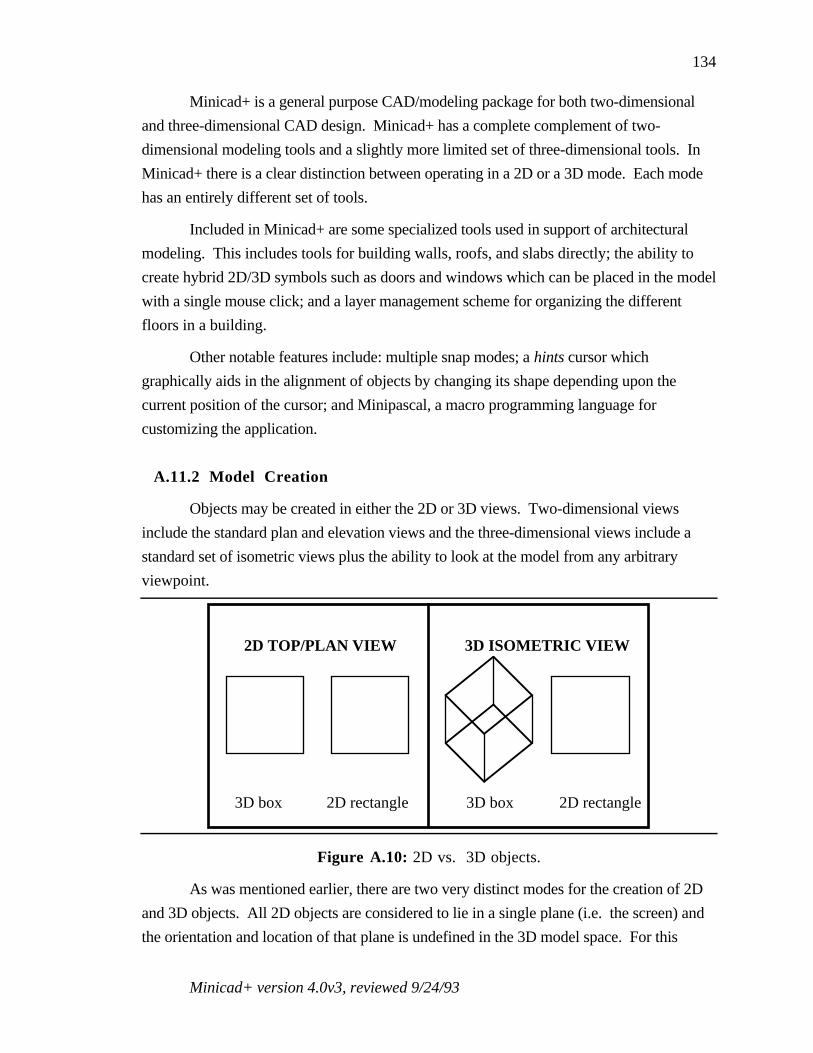
Minicad+ version 4.0v3, reviewed 9/24/93
134
Minicad+ is a general purpose CAD/modeling package for both two-dimensional
and three-dimensional CAD design. Minicad+ has a complete complement of two-
dimensional modeling tools and a slightly more limited set of three-dimensional tools. In
Minicad+ there is a clear distinction between operating in a 2D or a 3D mode. Each mode
has an entirely different set of tools.
Included in Minicad+ are some specialized tools used in support of architectural
modeling. This includes tools for building walls, roofs, and slabs directly; the ability to
create hybrid 2D/3D symbols such as doors and windows which can be placed in the model
with a single mouse click; and a layer management scheme for organizing the different
floors in a building.
Other notable features include: multiple snap modes; a hints cursor which
graphically aids in the alignment of objects by changing its shape depending upon the
current position of the cursor; and Minipascal, a macro programming language for
customizing the application.
A.11.2 Model Creation
Objects may be created in either the 2D or 3D views. Two-dimensional views
include the standard plan and elevation views and the three-dimensional views include a
standard set of isometric views plus the ability to look at the model from any arbitrary
viewpoint.
3D box 2D rectangle
2D TOP/PLAN VIEW 3D ISOMETRIC VIEW
3D box 2D rectangle
Figure A.10: 2D vs. 3D objects.
As was mentioned earlier, there are two very distinct modes for the creation of 2D
and 3D objects. All 2D objects are considered to lie in a single plane (i.e. the screen) and
the orientation and location of that plane is undefined in the 3D model space. For this
Minicad+ version 4.0v3, reviewed 9/24/93
135
reason, when a switch is made from a 2D to a 3D view, all 2D objects remain floating in
the plane of the screen, and do not move as the 3D viewpoint is changed. For example the
left half of Figure A.10 shows a 3D box and a 2D rectangle as seen in the 2D top/plan
view. The right half of Figure A.10 shows the same 3D box and 2D rectangle in one of the
3D isometric views. Note how the 2D rectangle remains in the plane of the screen and does
not have a corresponding 3D location. This is how the 2D box will look regardless of the
3D viewpoint chosen.
A two-dimensional outline may be extruded into 3D, but to fully transfer into the
three-dimensional world the object must then also be converted to 3D polygons (via menu
command).
Only the wall tool (in the 2D menu) creates hybrid 2D/3D objects. In the 2D plan
view, the wall tool creates a double line which indicates the wall thickness. When a switch
is made to a 3D view, the walls (unlike the other 2D objects), will switch from a 2D line to
a three-dimensional object (with corresponding position and orientation in the 3D modeling
space).
A certain number of tools are used to create objects directly in the 3D view. This
includes the 3D extrude tool, the 3D slab tool, the 3D polygon tool, and the 3D roof and 3D
sweep menu items.
The 3D extrude tool is used to create a multi-sided polyhedron with sides
perpendicular to the working plane. This is similar to using a 2D polygon tool except that
the polygon has an extrusion height set (via dialog box) by the user. The 3D slab tool
creates a three-dimensional box which can be used as the slab for the currently selected
floor. A 3D polygon is a two-dimensional shape which has position and orientation.
All objects created in the 3D view are created relative to the currently selected
working plane and there are assorted tools used for moving the working plane around to
the desired position and orientation (e.g. for creating 3D objects at different heights and
orientations)
A.11.3 Model Modification
Both the 2D and 3D modes allow for the standard types of model modifications.
Objects may be translated (using the selection pointer), rotated and scaled. In the 3D mode,
the rotation of objects may either be around the working plane normals or around some
secondary (user defined) vector. 3D objects can also be reflected about an axis and
reshaped (by moving selected vertices). For all of the modification operators, the operation
Minicad+ version 4.0v3, reviewed 9/24/93
136
can be performed on either the original object or a new object (a clone) can be created in the
new target location.
A.11.4 Model Interaction/Visualization
Both the 2D and 3D modes provide the ability to pan and zoom around the current
view-plane.
Almost half of the available three-dimensional tools in Minicad+ are used for
changing the view into the 3D modeling space. In addition to the pan and zoom tools
discussed above, Minicad+ also provides: 3D translate, view rotate, walkthrough, flyover,
translate along working plane normal, and rotate about working plane normal. Though a
large set of options, most of these view manipulation tools just represent a slightly different
way of moving around the three-dimensional world (each with a different set of constraints
on how you can move).
3D translate moves the eye-point in and out along the direction of view. View
rotate changes the angle at which the user is viewing the model (either around the direction
of view or around the X and Y axis of the screen). To quote the manual: view rotate "can
be so flexible that it is awkward to use". Walkthrough allows user centered motion and all
rotations are about the user viewpoint. Flythrough rotates the user view with the additional
restriction that the user view up is always constrained to an upright position. Working-
plane normal rotation and translation change the viewpoint relative to the currently defined
working plane.
A.11.5 Manual
Overall, the Minicad+ manuals are comprehensive and are fairly well written.
There is a complete user manual (plus index) and a separate tutorial manual (which focuses
on the creation of architectural models). Also included in the package is a separate manual
describing programming in Minipascal, a macro programming package for customizing the
application; and an introductory video which demonstrates the basic use of the package.
A.11.6 Comments/Impressions
Minicad's strengths lie primarily in the two-dimensional domain. Overall it seems
to be a sophisticated 2D CAD package that allows you to create complex two-dimensional
drawings. Minicad has several useful features such as a context-sensitive help bar and a
screen hints mode which helps you during drawing creation. The screen hints mode is a

Minicad+ version 4.0v3, reviewed 9/24/93
137
particularly useful feature which changes the cursor into a smart cursor which can indicate
snap points and alignment information. I also liked features such as the inclusion of a
rotated rectangle tool which allows you to draw non-axial rectangles.
Minicad+ is less strong as you move into the 3D domain. In fact, the 3D tools feel
more like something tacked onto a 2D package rather than an integral part of a unified
system for 2D/3D design. The strong division between the 2D and 3D worlds, though
useful in creating presentation drawings that include both 2D and 3D views, takes some
getting used to.
Minicad+ is also somewhat limited in terms of three-dimensional object creation
tools, only two tools on the 3D tool pallet are devoted to creating 3D objects and both of
these are limited to creating multi-sided objects with sides perpendicular to the working
plane. Though more complicated objects can be created using the menu items for 3D
extrusion and 3D surfaces of revolution, these features are not directly integrated as 3D
tools.
The majority of the Minicad+ 3D mode seems devoted to means of changing your
viewpoint in the 3D model space. 9 tools (when pan and zoom are included) are devoted to
changing your viewpoint relative to the model. Most of these, however, represent different
ways of doing the same thing. This part of the Minicad interface could be simplified and
reduced.
Minicad has the potential to be a very powerful modeler, however, this will require
some redesign and a more careful integration of the 2D and 3D modes.
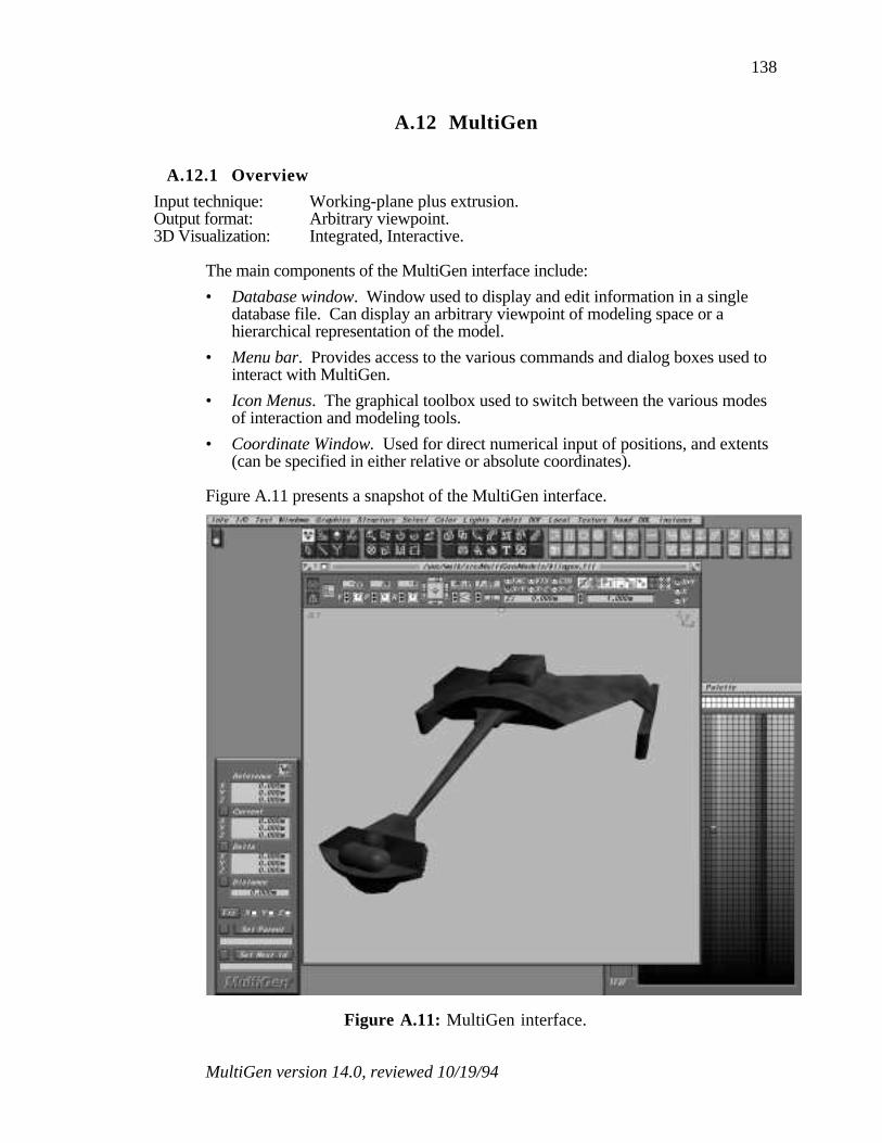
MultiGen version 14.0, reviewed 10/19/94
138
A.12 MultiGen
A.12.1 Overview
Input technique: Working-plane plus extrusion.Output format: Arbitrary viewpoint.3D Visualization: Integrated, Interactive.
The main components of the MultiGen interface include:
• Database window. Window used to display and edit information in a singledatabase file. Can display an arbitrary viewpoint of modeling space or ahierarchical representation of the model.
• Menu bar. Provides access to the various commands and dialog boxes used tointeract with MultiGen.
• Icon Menus. The graphical toolbox used to switch between the various modesof interaction and modeling tools.
• Coordinate Window. Used for direct numerical input of positions, and extents(can be specified in either relative or absolute coordinates).
Figure A.11 presents a snapshot of the MultiGen interface.
Figure A.11: MultiGen interface.

MultiGen version 14.0, reviewed 10/19/94
139
MultiGen is a high-end modeling system designed to run on Silicon Graphics
workstations. MultiGen is a general purpose modeler though its roots are in the flight
simulator industry (it still includes tools for generating runway lights for example).
The most notable features of MultiGen include multiple techniques for object
selection (including a hierarchical representation of the model) and a large number of
construction assists to help in the construction and positioning of models. The hierarchical
view allows the user to see a representation of the models hierarchical structure (showing
all parent-child relationships) and can be used to quickly select portions of the model for
later manipulation.
MultiGen allows the user to interact with the model at many different topological
levels; the user can select and manipulate vertices, edges, faces, objects, and groups of
objects.
MultiGen includes an extensive set of tools for applying and editing textures.
A.12.2 Model Creation
MultiGen is a working-plane-plus-extrusion system. The working plane can be:
aligned with the XY, YZ, and ZX planes, moved to any vertex (maintaining its current
orientation), aligned with any object face, or aligned with any three vertices. The working
plane can also be moved to any arbitrary position and orientation using numeric input.
MultiGen provides tools for the creation of irregular and regular polygons,
rectangles, spheres and strip faces (fixed width polygons along a path - ideal for roads).
All objects are created interactively (using the mouse) or with numeric input (to specify
absolute or relative positions of vertices). Two-dimensional faces can be extruded into
three-dimensional objects which have either walled (perpendicular) or peaked (converging)
sides. MultiGen also includes advanced tools for the creation of surfaces of revolution and
lofted objects (objects defined by a sequence of two-dimensional profiles). The default
behavior of most tools is controlled using a related preferences page.
All objects created in MultiGen are inserted into an object hierarchy which
encapsulates the relationship between objects, groups of objects, faces, edges and vertices.
The user can view a graphical representation of the hierarchy in which he can reorganize
structural relationships using commands or interactive drag and drop editing to detach and
attach nodes in the hierarchy (see below).
MultiGen has a large variety of construction assists. A rectangular or radial grid
can be used during construction to constrain the cursor position to regular, adjustable
MultiGen version 14.0, reviewed 10/19/94
140
spacings. The cursor can also be snapped to any vertex or edge using coordinate
referencing techniques. The referenced edge and vertex can be a part of the existing model
or they can be construction objects, temporary objects used solely as points of reference.
MultiGen includes many types of construction objects. Construction edges are used to
generate points parallel to edges, perpendicular to an edge or face, along a curve, along the
line connecting the midpoints of any two existing edges, or at the intersection of two
planes. Construction vertices are used to define points at the average value of a set of
vertices, at the intersection of two edges, at the point on a line or a plane closest to a
selected vertex, or at even intervals along a line.
A.12.3 Model Modification
MultiGen includes several techniques for object selection which facilitate interaction
with complex models. Objects can be selected: in the graphics view, in the hierarchy view,
and by attribute.
When selecting objects in the graphics view a topological level is used to control the
level of selection (vertices, edges, faces, objects, and groups of objects). The shrink faces
command is used to aid in the selection of coincident vertices by causing faces to
temporarily contract about their center (separating coincident vertices).
The hierarchical view is very useful when the model has grown complex enough
that it is difficult to select objects in the graphics view. Related segments of a model can be
selected using a single mouse click by selecting the appropriate node in the object
hierarchy.
Finally, objects may be selected by attributes (such as color) or boolean
combinations of attributes.
In MultiGen the standard tools to position, orient and scale an object are enhanced
by the numerous construction assists mentioned above. This makes it very easy to quickly
position objects relative to one another in the database.
Other transformation functions in MultiGen include: automatic level of detail
generation, a slice operator (to split an object along the working plane), tools to split faces,
and to add and position vertices.
A.12.4 Model Interaction/Visualization
One of the key advantages of MultiGen is that it runs on a Silicon Graphics
workstation; this provides the graphics power required for smooth interaction with complex

MultiGen version 14.0, reviewed 10/19/94
141
models. MultiGen is an integrated system, the modeling view and visualization view are
combined into one.
MultiGen allows you to rotate the viewpoint about the model, zoom in and out and
flythrough the model. It can sometimes be difficult to get a desired viewpoint using the
interactive controls. This is somewhat compensated for by the ability to save and recall
viewpoints. MultiGen also includes commands to automatically zoom in on the selected
portion of the model. To assist in interaction with complex models, MultiGen enables the
user to open a separate window in which he can work on a subset of model. All changes in
the new window will be reflected in the original model. Interaction with complex models is
also helped by the ability to turn off the display of selected portions of the model using the
hierarchical view.
A.12.5 Manual
The MultiGen manual is fairly well written and organized. A significant portion of
the manual is dedicated to MultiGen's texture mapping and editing features. Included in the
manual is a tutorial section which steps you through the creation of a typical scene.
Though useful, the tutorial is sometimes ambiguous in its description of the desired
operations.
MultiGen also includes a context-sensitive help mode which can be used to display
information about each icon and menu command.
A.12.6 Comments/Impressions
Several features help to make MultiGen a good choice for working with complex
models. The graphics power of Silicon Graphics Workstations enable an interactive
visualization which helps in the understanding of the model and in the specification of
positions, orientations, and extents. Numerous techniques for object selection make it easy
to isolate desired portions of the model for further manipulation. A large number of
construction assists help in the construction and positioning of objects relative to each
other. MultiGen also includes many tools for model cleanup not found in lower-end
modeling systems (including tools to check for non-coplanar vertices, duplicate vertices,
concave faces and objects, and to simplify faces sharing common edges). MultiGen also
has an extensive set of tools for dealing with texture maps (including a full texture editor).
The ability to interact with a hierarchical representation of the model is one of the
key advantages of MultiGen. It is very helpful in the selection and isolation of segments of

MultiGen version 14.0, reviewed 10/19/94
142
the model and it is a good practice to set up a structural hierarchy during, rather than after
model generation. Learning to use to hierarchy effectively, however, does take some time.
The disadvantages of MultiGen include a complex interface, a fairly limited set of
modeling primitives (limited to polygonal objects with no support for curved surfaces and
CSG operators), and a high price.

Sculpt 3D version 2.06, reviewed 7/21/93
143
A.13 Sculpt 3D
A.13.1 Overview
Input Technique: Orthogonal inputOutput format: Orthogonal3D Visualization: Separate, static
The main components of the Sculpt 3D interface include:
• Tri-View window. 3 orthogonal views used to interact with the model.
• Tri-View Palette. The graphical toolbox region of the Tri-View used to switchbetween the various modes of interaction and modeling tools.
• Menu bar. Provides access to the various commands and dialog boxes used tointeract with Sculpt 3D
• Coordinate dialog. Displays current mouse position and is used for numericinput.
• Scene dialog. Contains information about number of vertices, edges, and facesin the current scene plus memory information.
Figure A.12 presents a snapshot of the Sculpt 3D interface.
Figure A.12: Sculpt 3D interface.
Sculpt 3D version 2.06, reviewed 7/21/93
144
Sculpt 3D is a general purpose three-dimensional modeling tool. (Sculpt 4D is the
same 3D modeling package with the addition of animation tools).
Sculpt 3D is an orthogonal view system. In Sculpt 3D, the user directly specifies
the three-dimensional shape of all objects created. This is accomplished through the
specification of the X, Y and Z position of all the vertices and edges (and thus the faces)
that make up an object.
Visualization of Sculpt objects is either done directly in the modeling window
(which is in essence an orthographic wire frame view) or via higher quality ray traced
images displayed in a separate visualization window.
A.13.2 Model Creation
In Sculpt 3D, objects are entirely made up of triangular faces, each face made up of
vertices and edges. Objects are created in Sculpt using the Tri-View windows, three
orthogonal views into the three-dimensional modeling space. The creation of objects in
Sculpt requires the specification of:
1) the X, Y, and Z coordinate of each defining vertex in 3 space (either defined bythe position of the cursor in any two orthogonal views or by numeric input in acoordinate dialog box).
2) the connectivity of the vertices by edges.
3) the grouping of vertices and edges into triangular faces ( using the create facetool.
To facilitate the specification of all this information, Sculpt provides many means of
creating vertices (both connected and unconnected by edges) and Sculpt automatically
creates faces whenever three edges are connected together into a triangle.
To support the creation of complex three-dimensional shapes (which would nearly
be impossible if you had to explicitly specify the location of every vertex), Sculpt provides
a set of default objects (such as spheres, hemispheres, blocks, prisms, disks, and circles)
which can be incorporated into the model and then modified as desired. Sculpt also
provides several more advanced methods of creating objects such as reflections, and
surfaces of revolution (spin and twist).
A coordinate dialog box relays information to the user about the current cursor
location. Cursor position can be reported in absolute or relative coordinates. A temporary
origin can be defined for relative modes. The coordinate dialog box can also be used for
direct numeric input of cursor coordinates.

Sculpt 3D version 2.06, reviewed 7/21/93
145
A.13.3 Model Modification
Sculpt provides many different means of vertex selection and deselection, which is
often one of the most time-consuming modeling actions in an orthogonal input modeling
system. The basic goals of each of these methods is to provide a different method of
isolating and specifying the desired vertices.
Since many models tend to be quite regular and axis-aligned, selection of a single
vertex can often be quite confusing. Vertices that lie along a line orthogonal to one of the
view planes, for example, will all project to same point in that view. To disambiguate this,
vertex selection depends on specifying cursor position in multiple Sculpt windows, since
vertices in different locations in 3 space will have different positions in the three orthogonal
views. Even with three separate views, however, it still may be difficult to select a
particular vertex since it may be obscured by different vertices in each of the orthogonal
views.
In order to simplify the current view, Sculpt only renders the vertices that are
enclosed in the cube defined by the Tri-View windows, thus simplifying vertex selection.
By resizing each window or changing the level of zoom, you can change the portion of
modeling space that is enclosed by the Tri-View, thus isolating vertices of interest.
Vertex selection in more complex models is greatly helped by a hierarchy dialog.
This can be used to selectively name parts of a model. Once named, entire segments of a
model can be selected, deselected, deleted, and hidden. As the name implies, models can
also be arranged hierarchically (e.g. a door could be further broken down into door knobs,
hinges etc.)
Once selected, vertices may be moved, rotated, scaled (uniformly or along any
combination of individual axes), mirrored, duplicated, deleted, snapped to a grid (or a
plane or sphere), spun around an axis or twisted along a path. Magnet tools can be used to
apply a force to all selected vertices, moving them a distance proportional to the inverse of
the distance from the cursor.
A.13.4 Model Interaction/Visualization
Conventional scroll bars are provided for panning through the current model.
Movement can also be accomplished by grabbing the Tri-View rulers and moving them
over the desired amount. Tools are provided for zooming in and out from the current view,
with amount of zoom controlled by various combinations of key specified modifiers (e.g.

Sculpt 3D version 2.06, reviewed 7/21/93
146
zoom in 2X,4X, 1/2X etc.). Tri-Views can also be quickly centered around the current
modeling cursor location using the Center on Cursor button.
Sculpt 3D visualizations are static ray-traced images that are displayed in a separate
window. Image quality can be enhanced using textures and bump maps and selectable
levels of anti-aliasing, and dithering. Multiple lights can be placed in the scene and the
observer and target position can be specified using the Tri-View window. The speed of
rendering, however, is too slow for interactive viewing. Sculpt renderings are more useful
for final analysis of the modeled object and for final presentation. Most other times, the
user must use the three Tri-View windows as a wire-frame representation of the model.
This, however, is not optimum, since this requires the user to combine the information
from the three Tri-View windows in his head into a three-dimensional representation. It is
likely that some confusion will exist about the actual shape of the modeled object (due to
the ambiguity in the three views described above).
A.13.5 Manual
Overall, the manual is well written, with a good description of how to use the
modeler, a good index and a detailed functional reference. In addition to giving a
description of what each tool does, the Sculpt manual demonstrates how each tool would
be used, and gives examples of how to create sample objects. Each section of the manual
clearly lists the functions to be described, has a detailed description of those functions and
ends with a summary of what was learned.
Sculpt 3D comes with sample files and a straightforward tutorial that steps the user
through the basics of modeling using Sculpt 3D.
A.13.6 Comments/Impressions
Overall, Sculpt 3D is a consistently written, relatively powerful 3D modeler. All
tools have a predictable behavior with modifiers that exhibit consistent behavior across
related tools. Sculpt enables the user to create very complex three-dimensional shapes by
using low level primitives such as vertices and edges, combined with a complete set of
default objects and powerful modifying actions (such as spin, and reflect).
The use of low level primitives, however, is also one of the primary source of
difficulties when using Sculpt. Dealing directly with vertices and edges (instead of with
some higher level primitive) means that a considerable amount of Sculpt's resources must
be spent in providing ways of selecting, deselecting, and modifying vertices. This can be a
Sculpt 3D version 2.06, reviewed 7/21/93
147
hindrance since there are times when the user does not want to think in terms of vertices but
would rather think at a higher level (such as faces or objects). This is complicated by the
fact that, as models get more complex, the resulting views in the Tri-View windows can
become quite confusing. Vertices can become doubled (tripled, quadrupled.....) where a
single vertex in a view actually represents many vertices lying in a row. Though Sculpt
provides many means of selecting/disambiguating vertices, it sometimes can become quite a
chore isolating the desired vertices in a model.
Another difficulty with Sculpt is that it forces the user to think of a models in terms
of its three orthogonal projections. This makes it difficult to obtain the desired shape since
it is hard to determine how the desired shape decomposes into the three orthogonal
components.

Upfront version 2, reviewed 10/8/93
148
A.14 Upfront
A.14.1 Overview
Input Technique: Working-plane plus extrusion.Output format: Arbitrary viewpoint3D Visualization: Integrated, interactive
The main components of the Alias Upfront interface include:
• Workspace. 3D arbitrary viewpoint used to interact with the model.
• Main toolbox The graphical toolbox used to switch between the various modesof interaction and modeling tools.
• View toolbox. Used for changing the user's viewpoint on the modeling space.
• Message box. Used to prompt the user with information about the currentoperation.
Figure A.13 presents a snapshot of the Upfront interface.
Figure A.13: Upfront interface.

Upfront version 2, reviewed 10/8/93
149
Alias Upfront is a three-dimensional design package which is targeted for the
preliminary stages of architectural design. This means that the main objective of Upfront is
the exploration of spaces and shapes rather than the detailed design of a particular item. As
a result, the interface in Upfront is geared towards allowing the user to quickly create three-
dimensional shapes with minimal user interaction.
Alias Upfront is a member of the class of modelers in which the user creates objects
directly in a 3D perspective view. Unlike other modelers, however, object creation in
Upfront is solely done in a 3D view. Even though it is possible to view an object using
what looks like the standard plan and elevation views (orthogonal parallel projections),
these views are in fact 3D perspective views and not really parallel projections. Contrast
this with most other modelers that model in a 3D view, which also provide model
interaction in two-dimensional parallel projection windows (plan views).
Notable features of Alias Upfront include: modeling in fully shaded scenes, tools to
directly create walls with thickness, shadow calculations, and full floating point arithmetic.
A.14.2 Model Creation
Objects are created in Alias Upfront as follows:
• Select a tool (box, sphere cylinder etc.)
• Click to set base point
• Rubberband up and down to set object height (or use numeric input)
• Move cursor to define shape (e.g. click on each vertex for a wall or define theangle of revolution for a section of a sphere)
All objects in Upfront are created relative to a working plane. In Upfront, the
working plane is quickly moved to any surface by clicking on that surface with the mouse
cursor (unlike other modeling packages which have separate working-plane positioning
modes). This makes it easy to build objects relative to other objects (a vase on a table for
example). Selection of faces (for snapping of the working plane) is facilitated by several
factors. First, all objects in Upfront are fully shaded and not wireframe models. This
makes it easier to identify component faces. Second, the Upfront cursor changes shape
and orientation depending upon its current position in the model. Based upon the shape of
the cursor, the user can identify when the cursor is over a vertex, line or face.
Furthermore, the orientation of a face is indicated by displaying a line indicating the
direction of the surface normal.
Several constraint modifiers control the shape and orientation of the resulting
object. The direction tool determines if the extrusion direction is vertical, horizontal (e.g.

Upfront version 2, reviewed 10/8/93
150
for creating a dormer), or perpendicular to the current working surface. The height tool
determines the means of specifying the extrusion height of an object. Heights can either be
specified by rubber-banding, set to match the length on any line in the scene, or set to
match the height of any existing point or surface in the scene.
For all steps requiring specification of dimensions it is possible to alternate between
mouse input and numeric input. Numbers can be input directly and the cursor will move
appropriately. If however, you move the mouse again (after numeric input), then mouse
cursor control resumes.
In Upfront, objects are created in terms of surfaces (vs. specifying individual
vertices). By default, objects are single-sided (to speed up rendering) but can be promoted
to two-sided (to enable seeing the insides of a box, for example.
Upfront is clearly a preliminary design package (as advertised), consequently it is
somewhat limited in terms of the types of objects it can create directly. The main primitives
are box, cylinder, sphere, multi-sided polyhedra and wall. More complex objects can
created by performing intersection operations on objects but Upfront does not directly
include operators such as: surfaces of revolution and sweeps along paths (though surfaces
of revolution can be created by a modified use of the cylinder tool).
A.14.3 Model Modification
Entire objects or subsets of objects (e.g. a single line or face) can be moved,
rotated (around specified points), scaled and reshaped (by moving individual vertices, lines
or faces). The topological level of the selection (vertex, line, face, or object) depends on
the cursor location (and shape) at the time of selection. Position the cursor over a single
edge of the object and only that edge is selected.
During all modeling actions the cursor movement can be constrained to a surface,
an object edge, a line between any two points in the model, a surface defined by any three
points in the model or on an object edge with distance measured relative to an intersecting
surface.
A.14.4 Model Interaction/Visualization
All model interaction is done in the 3D perspective view. Interaction can be
performed from any viewpoint. The standard means of changing the view (pan, zoom) are
included.

Upfront version 2, reviewed 10/8/93
151
Since all interaction with the model is done in the 3D view, it is important to be able
to change the viewpoint relative to the model in order to aid in the understanding of the 3D
shape of the object being created. There are several ways to change the viewpoint and view
direction in Alias Upfront.
The view toolbox provides several modes for changing the viewpoint. These
roughly correspond to: changing the eye-point, changing the center-of-interest, changing
the distance between the eye-point and the center-of-interest, and changing the field-of-
view (FOV). All of these can be controlled by moving the mouse in the main window or
by clicking on control buttons in the view toolbox.
All of these parameters can be changed simultaneously by selecting the view tool.
One of the most complex tools to use, the view tool sets the position and height of the
center-of-interest, the position and height of the eye-point (and thus the distance between
the two), and the field-of-view. This involves several clicks, rubberbandings and mouse
movements; the end result of which is a new viewpoint on the scene.
Several default views may be chosen from via menu selection including plan view
and elevation view (the direction of view being set by drawing a line in the model
specifying the look vector).
One nice feature which aids in the interpretation of the 3D shapes shown in the 3D
perspective projection is the ability to calculate and display shadows. This helps the user
understand the three dimensional relationship between objects. The shadows help
immeasurably in letting the user determine if an object is resting on the ground plane or
floating several units above.
A.14.5 Manual
Upfront includes a detailed user manual (plus index) and a tutorial which walks you
through the basics of model creation. Since Upfront is a fairly simple package (in terms of
the number of features) the tutorial quickly gives the user a fairly complete understanding
of the package in just a few hours. Alias also includes a quick reference card, something
essential in helping the user remember the function of the various tools.
A.14.6 Comments/Impressions
Alias Upfront has attempted to deal with some of the difficulty in working directly
in a three-dimensional projection. Having fully shaded objects and shadows helps in
understanding the 3D shape of the objects being created. It is easier to create an object

Upfront version 2, reviewed 10/8/93
152
where you want in Upfront because of the ease moving the working plane to the surfaces
and edges of existing objects (though in some cases this necessitates the creation of
construction surfaces - see Section A.2.1). The changing cursor shape and orientation also
help in interpreting the current cursor position which is complicated by working in a
perspective projection (see Section A.2.2).
Upfront suffers from the lack of more complex operators (such as sweeps along
paths), though the inclusion of such operators would naturally complicate the user
interface.
Though the ability to quickly change viewpoints is nice (and helps in 3D shape
understanding), Upfront would benefit from a more interactive 3D visualization.

WalkThrough version 1.1.3, reviewed 6/3/93
153
A.15 WalkThrough
A.15.1 Overview
Input Technique: Working-plane plus extrusion.Output format: 2D plan view3D Visualization: Separate, interactive
The main components of the Virtus WalkThrough interface include:
• Design view. 2D plan views used to interact with the model.
• Walk View. An interactive visualization of the model.
• Tools Window The graphical toolbox used to switch between the variousmodes of interaction and modeling tools.
• Surface Editor. Used to add surface features (such as window and dooropenings).
• Tumble Editor. Used to add a surface to a selected object by slicing off a pieceof the object.
Figure A.14 presents a snapshot of the WalkThrough interface.
Figure A.14: WalkThrough interface.
Virtus WalkThrough is a general purpose modeler with an emphasis on architectural
design. Virtus can be used to create and manipulate three-dimensional models. Objects are

WalkThrough version 1.1.3, reviewed 6/3/93
154
generated in Virtus using 2D plan views in which (convex) polygonal outlines are created
which are extruded into the third dimension based upon separate depth controls. One of the
most notable features of Virtus is that it provides an interactive walkthrough of the current
model in which the user can move freely and observe the model from all directions.
Another notable feature of Virtus is the ability to add features (primarily holes) to
the faces of polygonal objects.
A.15.2 Model Creation
Models are created using the working-plane plus extrusion method. The elevation
of the current working plane and the extrusion height are controlled using a depth slider
(which is in a separate window or in a view orthogonal to the current working plane). The
depth slider can also be used to change the extrusion height of an existing object.
Virtus provides modeling aids such as a ruler for determining current cursor
position and a modeling grid. Also included are movable alignment guides which can be
used in the alignment of objects. Note that the spacing of the modeling grid is dependent
upon the current level of zoom in the active window (which determines the spacing of the
tic marks on the ruler). To get a particular spacing, you must zoom your view in or out.
Some of the primary requirements of all Virtus models (which somewhat restrict the
flexibility of the program) are: 1) Virtus can only create convex outlines, 2) polyhedra must
not intersect (they can either be contained or entirely non-intersecting).
A.15.3 Model Modification
Virtus allows the standard operations such as rotation, skewing, and scaling. Some
difficulty results from the fact that the three-dimensional objects are treated as two-
dimensional outlines extruded along an orthogonal axis. This means that objects have a
direction associated with them and are not truly general 3D shapes. Thus it is not possible
to modify all aspects of the shape of a 3D object in a view that is orthogonal to view in
which the two-dimensional outline was created. You can modify the extrusion depth, for
example, but not the shape of the outline. Objects can be rotated, skewed and scaled in the
orthogonal view but if the two-dimensional outline is rotated out of the plane of creation,
the object must be unrotated if the polygonal outline needs to be modified.
An important feature of Virtus is that it allows the modification and editing of
specific faces of an object. This means that properties of an object (such as color, and
opacity) can be set on a face by face basis. It is also possible to add features to the

WalkThrough version 1.1.3, reviewed 6/3/93
155
individual faces of an object. These features can range from opaque to transparent which
will have corresponding results ranging from colored features to holes in the face.
A.15.4 Model Interaction/Visualization
All modifications of the model are performed in the 2D plan view (Design View).
User can select any one of 6 orthogonal views to work in (and multiple orthogonal views
may be open at any one time).
Virtus uses scroll bars to pan around the Design view and zoom in/out buttons to
move in/out in predetermined size steps. There is also a zoom-in selection marquee where
the desired portion of the Design view is framed in a marquee and it is expanded to fill the
design view.
Also provided are menu options for recentering the modeling space on the location
of the virtual observer (the eye-point in the Walk View) and to recenter the Design view at
origin.
The primary 3D visualization in Virtus is in the Walk mode. In this mode, the user
moves around the Virtus model through interaction in the Walk view. Using a mouse (with
different modifier keys available) the user can change position relative to the model, view
direction, and view orientation. By restricting the allowable type of objects to be convex
non-intersecting polyhedra, Virtus has achieved a relatively fast rendering speed.
Renderings in Virtus, however, are often inaccurate, with the depth ordering of objects in
error and/or their shapes grossly distorted.
A.15.5 Manual
The manual is well written and easy to understand. It includes a detailed tutorial
which steps you through the creation of a basic object and explains the manipulation of and
interaction with that object. A new user could sit down and learn Virtus in a few short
hours. This is facilitated by the fact that Virtus is a fairly straightforward program with
relatively few tools to learn how to use.
A.15.6 Comments/Impressions
The most significant feature of Virtus is its interactive, three-dimensional walk
view. The ability to interactively move through a model and change views in real time is a
very powerful feature. Unfortunately, Virtus is hampered by the day-to-day frustrations of
bugs (e.g. the incorrect computation of containment of small objects) and other

WalkThrough version 1.1.3, reviewed 6/3/93
156
shortcomings (in particular the lack of numeric input). Also, dealing with the constraint
that objects must be convex and non-interpenetrating makes it difficult to create arbitrary
complex shapes in Virtus.

REFERENCES
Angus, Ian and Henry A. Sowizral (1994). “Embedding the 2D interaction metaphor in a
real 3D virtual environment.” Boeing Computer Services, Technical Report.
Athènes, S. (1984). “Adaptabilité et développement de la posture manuelle dans l'écriture:
Etude comparative du droiter et du guacher. (Adaptability and development of
manual posture in handwriting: a study comparing right-handers and left-handers).”
University of Aix-Marseille II, France, Unpublished memorandum.
Badler, Norman I., Kamran H. Manoochehri and David Baraff (1986). “Multi-dimensional
input techniques and articulated figure positioning by multiple constraints.”
Proceedings of 1986 Workshop on Interactive 3D Graphics (Chapel Hill, NC),
ACM, pp. 151-69.
Balakrishnan, Ravin, Thomas Baudel, Gordon Kurtenbach and George Fitzmaurice
(1997). “The Rockin' Mouse: integral 3D manipulation on a plane.” Proceedings of
CHI '97 (Atlanta, GA), ACM, pp. 311-318.
Balakrishnan, Ravin and Scott I. MacKenzie (1997). “Performance differences in the
fingers, wrist, and forearm in computer input control.” Proceedings of CHI '97
(Atlanta, GA), ACM, pp. 303-310.
Bier, Eric Allan (1986). “Skitters and jacks: interactive 3D positioning tools.” Proceedings
of the 1986 Workshop on Interactive 3D Graphics (Chapel Hill, NC), ACM, pp.
183-96.
Bier, Eric Allen (1990). “Snap-dragging in three dimensions.” Proceedings of the 1990
Symposium on Interactive 3D Graphics (Snowbird, UT), ACM, pp. 193-204.
Bier, Eric A. and Maureen C. Stone (1986). “Snap-dragging (graphics).” Proceedings of
SIGGRAPH '86 (Dallas, TX). In Computer Graphics, 20(4), ACM, pp. 233-40.
Bier, Eric A., Maureen C. Stone, Ken Fishkin, William Buxton and Thomas Baudel
(1994). “A taxonomy of see through tools.” Proceedings of CHI '94 (Boston,
MA), ACM, pp. 358-364.
Bier, Eric Allen, Maureen C. Stone, Ken Pier, William Buxton and Tony D. DeRose
(1993). “Toolglass and magic lenses: the see-through interface.” Proceedings of
SIGGRAPH '93 (Anaheim, CA). In Computer Graphics Proceedings, Annual
Conference Series, ACM, pp. 73-80.

158
Boff, Kenneth R., Lloyd Kaufman and James P. Thomas, Eds. (1986). Handbook of
Perception and Human Performance. New York, John Wiley and Sons.
Bolt, Richard A. (1980). “Put-that-there.” Proceedings of SIGGRAPH '80 (Seattle, WA).
In Computer Graphics, 14(3), ACM, pp. 262-270.
Bolt, Richard A. and Edward Herranz (1992). “Two-handed gesture in multi-modal natural
dialog.” Proceedings of UIST '92 (Monterey, CA), ACM, pp. 7-14.
Bowman, Doug and Larry F. Hodges (1995). “Immersive design tools for virtual
environments.” SIGGRAPH 95 Technical Sketch (Los Angeles, CA), ACM.
Bowman, Doug and Larry F. Hodges (1997). “An evaluation of techniques for grabbing
and manipulating remote objects in immersive virtual environments.” Proceedings
of the 1997 Symposium on Interactive 3D Graphics (Providence, RI), ACM, pp.
35-38.
Britton, Edward G., James S. Lipscomb and Michael E. Pique (1978). “Making nested
rotations convenient for the user.” Proceedings of SIGGRAPH '78 (Atlanta, GA).
In Computer Graphics, 12(3), , pp. 222-227.
Brooks, Frederick P., Jr. (1986). “Walkthrough-a dynamic graphics system for simulating
virtual buildings.” Proceedings of the 1986 Workshop on Interactive 3D Graphics
(Chapel Hill, NC), ACM, pp. 9-22.
Brooks, Frederick P., Jr. (1994). Personal Communication.
Bryson, Steve and Creon Levit (1992). “The virtual wind tunnel.” IEEE Computer
Graphics & Applications 12(4), pp. 25-34.
Bukowski, Richard W. and Carlo H. Sequin (1995). “Object associations: a simple and
practical approach to virtual 3D manipulation.” Proceedings of the 1995
Symposium on Interactive 3D Graphics (Monterey, CA), ACM, pp. 131-138.
Butterworth, Jeff, Andrew Davidson, Stephen Hench and T. Marc Olano (1992). “3DM: a
three-dimensional modeler using a head-mounted display.” Proceedings 1992
Symposium on Interactive 3D Graphics (Boston, MA). In Computer Graphics,
25(2), ACM, pp. 135-138.
Buxton, William and Brad A. Myers (1986). “A study in two-handed input.” Proceedings
of CHI '86 (Boston, MA), ACM, pp. 321-326.
159
Chen, Michael, S. Joy Mountford and Abigail Sellen (1988). “A study in interactive 3D
rotation using 2D control devices.” Proceedings of SIGGRAPH '88 (Atlanta, GA).
In Computer Graphics, 22(4), ACM, pp. 121-129.
Chung, James (1994). Intuitive Navigation in the Targeting of Radiation Therapy
Treatment Beams. University of North Carolina, Ph.D. Thesis.
Clark, James H. (1976). “Designing surfaces in 3-D.” Communications of the ACM 19(8),
pp. 454-460.
Conner, D. Brookshire, Scott S. Snibbe, Kenneth P. Herndon, Daniel C. Robbins, Robert
C. Zeleznik and Andries vanDam (1992). “Three-dimensional widgets.”
Proceedings of the 1992 Symposium on Interactive 3D Graphics (Boston, MA). In
Computer Graphics, 25(2), ACM, pp. 183-188.
Cutler, Lawrence D., Bernd Fröhlich and Pat Hanrahan (1997). “Two-handed direct
manipulation on the responsive workbench.” Proceedings of the 1997 Symposium
on Interactive 3D Graphics (Providence, RI), ACM, pp. 107-114.
Davies, Char and John Harrison (1996). “Osmose: towards broadening the aesthetics of
virtual reality.” Computer Graphics 30(4), pp. 25-28.
Deering, Michael F. (1996). “The holoSketch VR sketching system.” Communications of
the ACM 39(5), pp. 54-61.
Durlach, Nathaniel I. and Anne S. Mavor, Eds. (1995). Virtual Reality: Scientific and
Technological Challenges. Washington, D.C., National Academy Press.
EVL, Electronic Visualization Laboratory at the University of Illinois at Chicago (1997).
“ImmersaDesk.” http://www.evl.uic.edu/EVL/VR/systems.html.
Fakespace, Inc. (1997). “Immersive workbench.” URL: http://www.fakespace.com/.
Fitzmaurice, George W. and William Buxton (1997). “An empirical evaluation of graspable
user interfaces: towards specialized space-multiplexed input.” Proceedings of CHI
'97 (Atlanta, GA), ACM, pp. 43-50.
Fitzmaurice, George W., Hiroshi Ishii and William Buxton (1995). “Bricks: laying the
foundations for graspable user interfaces.” Proceedings of the CHI '95 (Denver,
CO), ACM, pp. 442-449.
Fuchs, Henry, John Poulton, John Eyles, Trey Greer, Jack Goldfeather, David Ellsworth,
Steve Molnar, Greg Turk, Brice Tebbs and Laura Israel (1989). “Pixel-Planes 5: a
heterogeneous multiprocessor graphics system using processor-enhanced
160
memories.” Proceedings of SIGGRAPH '89 (Boston, MA). In Computer
Graphics, 23(3), ACM, pp. 79-88.
Gobbetti, Enrico and Jean-Francis Balaguer (1993). “VB2-an architecture for interaction in
synthetic worlds.” Proceedings of UIST '93 (Atlanta, GA), , pp. 167-78.
Gobbetti, Enrico and Jean-Francis Balaguer (1995). “An integrated environment to visually
construct 3D animations.” Proceedings of SIGGRAPH '95 (Los Angeles, CA). In
Computer Graphics Proceedings, Annual Conference Series, , pp. 395-8.
Goble, John C., Ken Hinckley, Randy Pausch, John W. Snell and Neal F. Kassell
(1995). “Two-handed spatial interface tools for neurosurgical planning.” Computer
28(7), pp. 20-6.
Gregory, Richard L. (1973). Eye and Brain. London, World University Library.
Guiard, Yves (1987). “Asymmetric division of labor in human skilled bimanual action: the
kinematic chain as a model.” The Journal of Motor Behavior 19(4), pp. 486-517.
Halliday, Sean and Mark Green (1996). “A geometric modeling and animation system for
virtual reality.” Communications of the ACM 39(5), pp. 46-53.
Hauptmann, Alexander (1989). “Speech and gestures for graphic image manipulation.”
Proceedings of CHI '89 (Austin, TX), ACM, pp. 241-245.
Herndon, Kenneth P., Robert C. Zeleznik, Daniel C. Robbins, D. Brookshire Conner,
Scott S. Snibbe and Andries Van Dam (1992). “Interactive shadows.” Proceedings
of UIST '92 (Monterey, CA), ACM, pp. 1-6.
Hinkley, Ken (1996). Haptic Issues for Virtual Manipulation. Department of Computer
Science, University of Virginia, Ph.D. thesis.
Hinkley, Ken, Randy Pausch, John C. Goble and Neal F. Kassell (1994). “Passive real-
world interface props for neurosurgical visualization.” Proceedings of CHI '94
(Boston, MA), ACM, pp. 452-458.
Hunter, Ian W., Doukoglou D. Tilemachos, Serge R. Lafontaine, Paul G. Charette,
Lynette A. Jones, Mark A. Sagar, Gordon D. Mallinson and Peter J. Hunter
(1993). “A teleoperated microsurgical robot and associated virtual environment for
eye surgery.” Presence 2(4), pp. 265-280.
Kabbash, Paul, William Buxton and Abigail Sellen (1994). “Two-handed input in a
compound task.” Proceedings of CHI '94 (Boston, MA), ACM, pp. 417-423.
161
Kessler, G. Drew, Larry F. Hodges and Neff Walker (1995). “Evaluation of the
CyberGlove(TM) as a whole hand input device.” ACM Transactions on Computer-
Human Interaction 2(4), pp. 263-283.
Kijima, Ryugo and Michitaka Hirose (1996). “Representative spherical plane method and
composition of object manipulation methods.” Proceedings of the 1996 Virtual
Reality Annual International Symposium (Santa Clara, CA), IEEE, pp. 196-202.
Krueger, Myron W. (1991). Artificial Reality II. Reading, MA, Addison-Wesley.
Krueger, Myron W. (1993). “Environmental technology: making the real world virtual.”
Communications of the ACM 36(7), pp. 36-37.
Krueger, Wolfgang and Bernd Fröhlich (1994). “The responsive workbench (virtual work
environment).” IEEE Computer Graphics and Applications 14(3), pp. 12-15.
Kurtenbach, Gordon and William Buxton (1991). “GEdit: a testbed for editing by
contiguous gestures.” SIGGCHI Bulletin 23(2), pp. 22-26.
Kurtenbach, Gordon and William Buxton (1993). “The limits of expert performance using
hierarchic marking menus.” Proceedings of INTERCHI '93 (Amsterdam,
Netherlands), IOS Press, pp. 482-487.
Kurtenbach, Gordon, George Fitzmaurice, Thomas Baudel and William Buxton (1997).
“The design and evaluation of a GUI paradigm based on tablets, two-hands, and
transparency.” Proceedings of CHI '97 (Atlanta, GA), ACM, pp. 35-42.
Leganchuk, Andrea, Shumin Zhai and William Buxton (1997). “Bimanual direct
manipulation in area sweeping tasks.” URL:
http://www.dgp.toronto.edu/people/andrea/bimanual.html.
Liang, J. and M. Green (1993). “Highly interactive 3D geometric modeling.” Proceedings
of VIDEA 93. Visualization and Intelligent Design in Engineering And Architecture
(Southampton, UK), Comput. Mech. Publications, pp. 269-79.
Liang, Jiandong and Mark Green (1994). “JDCAD: a highly interactive 3D modeling
system.” Computers & Graphics 18(4), pp. 499-506.
Macedonia, Michael R., Michael J. Zyda, David R. Pratt, Paul T. Barham and Steven
Zeswitz (1994). “NPSNET: a network software architecture for large scale virtual
environments.” Presence 3(4), pp. 265-287.

162
MacKenzie, I. Scott, Blair Nonnecke, Stan Riddersma, Craig McQueen and Malcolm Meltz
(1994). “Alphanumeric entry on pen-based computers.” International Journal of
Human-Computer Studies 41, pp. 775-792.
Mapes, Daniel P. and J. Michael Moshell (1995). “A two-handed interface for object
manipulation in virtual environments.” Presence 4(4), pp. 403-416.
Mine, Mark (1997). “ISAAC: a meta-CAD system for virtual environments.” Computer-
Aided Design , pp. to appear.
Mine, Mark R. (1993). “Characterization of end-to-end delays in head-mounted display
systems.” University of North Carolina, Technical Report TR93-001.
Mine, Mark R. (1996). “Working in a virtual world: interaction techniques used in the
chapel hill immersive modeling program.” University of North Carolina, Technical
Report TR96-029.
MultiGen (1997). “SmartSceneTM.” URL: http://www.multigen.com/smart.htm.
Nielson, Gregory M. and Dan R. Olsen, Jr. (1986). “Direct manipulation techniques for
3D objects using 2D locator devices.” Proceedings of the 1986 Workshop on
Interactive 3D Graphics (Chapel Hill, NC), ACM, pp. 175-82.
Norman, Donald A. (1988). The Psychology of Everyday Things. New York, Basic
Books.
Pausch, Randy, Tommy Burnette, Dan Brockway and Michael E. Weiblen (1995).
“Navigation and locomotion in virtual worlds via flight into hand-held miniatures.”
Proceedings of SIGGRAPH '95 (Los Angeles, CA). In Computer Graphics
Proceedings, Annual Conference Series, ACM, pp. 399-400.
Pausch, Randy, Jon Snoddy, Robert Taylor, Scott Watson and Eric Haseltine (1996).
“Disney's Aladdin: first steps toward storytelling in virtual reality.” Proceedings of
SIGGRAPH '96 (New Orleans, LA). In Computer Graphics Proceedings, Annual
Conference Series, ACM, pp. 193-202.
Pierce, Jeffrey S. , Andrew Forsberg, Matthew J. Conway, Seung Hong, Robert Zeleznik
and Mark R. Mine (1997). “Image plane interaction techniques in 3D immersive
environments.” Proceedings of the 1997 Symposium on Interactive 3D Graphics
(Providence, RI), ACM, pp. 39-44.
Poston, Timothy and Luis Serra (1994). “The virtual workbench: dextrous VR.”
Proceedings of the VRST '94 (Singapore), ACM, pp. 111-121.
163
Poston, Timothy and Luis Serra (1996). “Dextrous virtual work.” Communications of the
ACM 39(5), pp. 37-45.
Poupyrev, Ivan, Mark Billinghurst, Suzanne Weghorst and Tadao Ichikawa (1996). “The
Go-Go interaction technique: non-linear mapping for direct manipulation in VR.”
Proceedings of UIST '96 (Seattle, WA), ACM, pp. 79-80.
Rothbaum, B., L. Hodges, R. Kooper, D. Opdyke, J. Williford and M. North (1995).
“Effectiveness of computer-generated (virtual reality) graded exposure in the
treatment of acrophobia.” American Journal of Psychiatry 152(4), pp. 626-628.
Sachs, Emanuel, Andrew Roberts and David Stoops (1991). “3-Draw: a tool for designing
3D shapes.” IEEE Computer Graphics and Applications 11(6), pp. 18- 26.
Schmandt, Christopher (1983). “Spatial input/display correspondence in a stereoscopic
computer graphic work station.” Proceedings of SIGGRAPH '83 (Detroit, MI). In
Computer Graphics, 17,(3), ACM, pp. 253-61.
Shaw, Chris and Mark Green (1994). “Two-handed polygonal surface design.”
Proceedings of UIST '94 (Marina del Rey, CA), ACM, pp. 205-12.
Shoemake, Kenneth (1992). “Arcball: a user interface for specifying three-dimensional
orientation using a mouse.” Proceedings of Graphics Interface '92 (Vancouver,
BC, Canada), Canadian Inf. Process. Soc, pp. 151-6.
Stanford, University (1997). “Responsive workbench.” http://www-
graphics.stanford.edu/projects/RWB/.
Stoakley, Richard, Matthew J. Conway and Randy Pausch (1995). “Virtual reality on a
WIM: interactive worlds in miniature.” Proceedings of CHI '95 (Denver, CO),
ACM, pp. 265-272.
Taylor, Russell M, Warren Robinett, Vernon L. Chi, Frederick P. Jr. Brooks, William V.
Wright, Stanley Williams and Erik J. Snyder (1993). “The Nanomanipulator: a
virtual-reality interface for a scanning tunnel microscope.” Proceedings of
SIGGRAPH '93 (Anaheim, CA). In Computer Graphics Proceedings, Annual
Conference Series, ACM, pp. 127-134.
Teller, Seth J. and Carlo H. Sequin (1991). “Visibility preprocessing for interactive
walkthroughs.” Proceedings of SIGGRAPH '91 (Las Vegas, NV). In Computer
Graphics, 25(4), ACM, pp. 61-69.

164
Thorison, Kristinn R., D.B. Koons and Richard A. Bolt (1992). “Multi-modal natural
dialogue.” Proceedings of CHI '92 (Monterey, CA), ACM, pp. 653-654.
UNC, the University of North Carolina nanoManipulator project (1997). “The
nanoManipulator.” http://www.cs.unc.edu/Research/nano.
van Emmerik, M.J.G.M. (1990). “A direct manipulation technique for specifying 3D
object transformations with a 2D input device.” Computer Graphics Forum 9(4),
pp. 355-61.
Veniola, Dan (1993). “Facile 3D direct manipulation.” Proceedings of INTERCHI '93
(Amsterdam, Netherlands), IOS Press, pp. 31-36.
Ware, Colin and Danny R. Jessome (1988). “Using the bat: a six-dimensional mouse for
object placement.” IEEE Computer Graphics and Applications 8(6), pp. 65- 70.
Weimer, David and S.K. Ganapathy (1989). “A synthetic visual environment with hand
gesturing and voice input.” Proceedings of CHI '89 (Austin, TX), ACM, pp. 235-
40.
Wilson, John R., David J. Brown, Susan V. Cobb, Mirabelle M. D'Cruz and Richard M.
Eastgate (1995). “Manufacturing operations in virtual environments (MOVE).”
Presence 4(3), pp. 306-317.
Witmer, Bob G., John H. Bailey and Bruce Knerr, W. (1995). “Training dismounted
soldiers in virtual environments: route learning and transfer.” United States Army
Research Institute for the Behavioral and Social Sciences, Technical Report 1022.
Wloka, Matthias M. and Eliot Greenfield (1995). “The virtual tricorder: a uniform interface
for virtual reality.” Proceedings of UIST '95 (Pittsburgh, PA), ACM, pp. 39-40.
Zeleznik, Robert, Kenneth P. Herndon and John F. Hughes (1996). “SKETCH: an
interface for sketching 3D scenes.” Proceedings of SIGGRAPH '96 (New Orleans,
LA). In Computer Graphics Proceedings, Annual Conference Series, ACM, pp.
163-170.
Zeleznik, Robert C., Andrew S. Forsberg and Paul S. Strauss (1997). “Two pointer input
for 3D interaction.” Proceedings of the 1997 Symposium on Interactive 3D
Graphics (Providence, RI), ACM, pp. 115-120.
Zhai, Shumin and Paul Milgram (1993). “Human performance evaluation of manipulation
schemes in virtual environments.” Proceedings of the 1993 Virtual Reality Annual
International Symposium (Seattle, WA), IEEE, pp. 155-61.

165
Zhai, Shumin, Paul Milgram and William Buxton (1996). “The influence of muscle groups
on performance of multiple degree-of-freedom input.” Proceedings of CHI '96
(Vancouver, BC), ACM, pp. 308-315.