exploiting sleep mode for memory and other...
TRANSCRIPT
VLSI DESIGN1998, Vol. 7, No. 3, pp. 271--287Reprints available directly from the publisherPhotocopying permitted by license only
(C) 1997 OPA (Overseas Publishers Association)Amsterdam B.V. Published under license
under the Gordon and Breach SciencePublishers imprint.
Printed in India.
Exploiting Sleep Mode for Memory Partitioning andOther Applications*
AMIR H. FARRAHI*, GUSTAVO E. TILLEZ and MAJID SARRAFZADEH**
Department of Electrical Engineering and Computer Science,Northwestern University, Evanston, IL 60208
Sleep mode operation and exploiting it to minimize the average power consumption areof great importance in modern VLSI circuits. In general, sleep mode refers to the modein which part(s) of the system are idle. In this paper, we study the problem ofpartitioning a circuit according to the activity patterns of its elements such that circuitelements with similar activity patterns are packed into the same partition. Then apartition can be placed in sleep mode during the time intervals all elements contained inthat partition are idle. We formulate the partitioning problem to exploit sleep modeoperation and show that the problem is NP-complete. We present polynomial timealgorithms for practical classes of the problem. Applications of the problem to memoryand module partitioning and clock gating are discussed. The experimental data confirmthat a careful partitioning allows upto 40% more sleep time which could be exploited tominimize the average power consumption.
Keywords." Power minimization, sleep mode, partitioning, NP-Completeness
1. INTRODUCTION
Advances in VLSI and packaging technologieshave increased the average transistor count in achip by about one-hundredfold every decade [2],allowing much more complex functionality. More-over, the advent of portable and mobile commu-nication and computing services has stirred a greatdeal of interest in both the commercial andresearch areas. The dissipation of the heat genera-
ted by highly integrated circuits is a crucial factorbecause virtually all failure mechanisms areboosted at higher temperatures [2]. The minimiza-tion of power consumption in modern circuits istherefore of great importance. Due to thisimportance, there has been considerable shift ofattention in the logic and layout synthesis areas[14, 17, 20, 22, 23] and more recently in high-levelsynthesis [4, 5, 15] from the delay and areaminimization issues towards low power design.
*A preliminary version of this work appeared in the Proceedings of the 32nd Design Automation Conference, San Francisco, CA.ndJune 1995. "Memory segmentation to exploit sleep mode operation", 32 Design automation Conference, San Francisco, CA, June
1995, pp 36-41. Copyright (c) 1995, association for Computing machinery, Inc (Acm). Reprinted by Permission.**Corresponding author.*Present address: IBM T. J. Watson Research Center, P. O. Box 218, Yorktown Heights, NY 10598.
271
272 A.H. FARRAHI et al.
Previous research for low power synthesis ofdigital circuits has focused on issues such asactivity-driven technology decomposition andmapping [17 20, 22], low-power state assignment[12, 21], architectural transformation and reduc-tion of power supply voltage [4], wire and driversizing [6, 18], and reversible and adiabatic comput-ing [7, 26]. For a survey of these techniques see [8].
Transition density or average switching rate atdifferent sites in a circuit is introduced in [16] as aquantity to measure the circuit activity, which canbe used to estimate the average power consump-tion in a digital circuit. Recent studies [1] indicatethat the clock signal and memory unit in digitalcomputers, each consumes somewhere between 15to 45 percent of the total power. This suggests goodopportunities for savings in power consumptiondue to these sources. Exploiting sleep mode opera-tion is an attempt to do so. In general, the term sleepmode refers to the mode in which there is no activityin part(s) of the system during certain periods oftime. The sleep mode issue can be studied atdifferent levels, e.g., behavioral level, register-transfer level (RTL), logic level and transistor level.
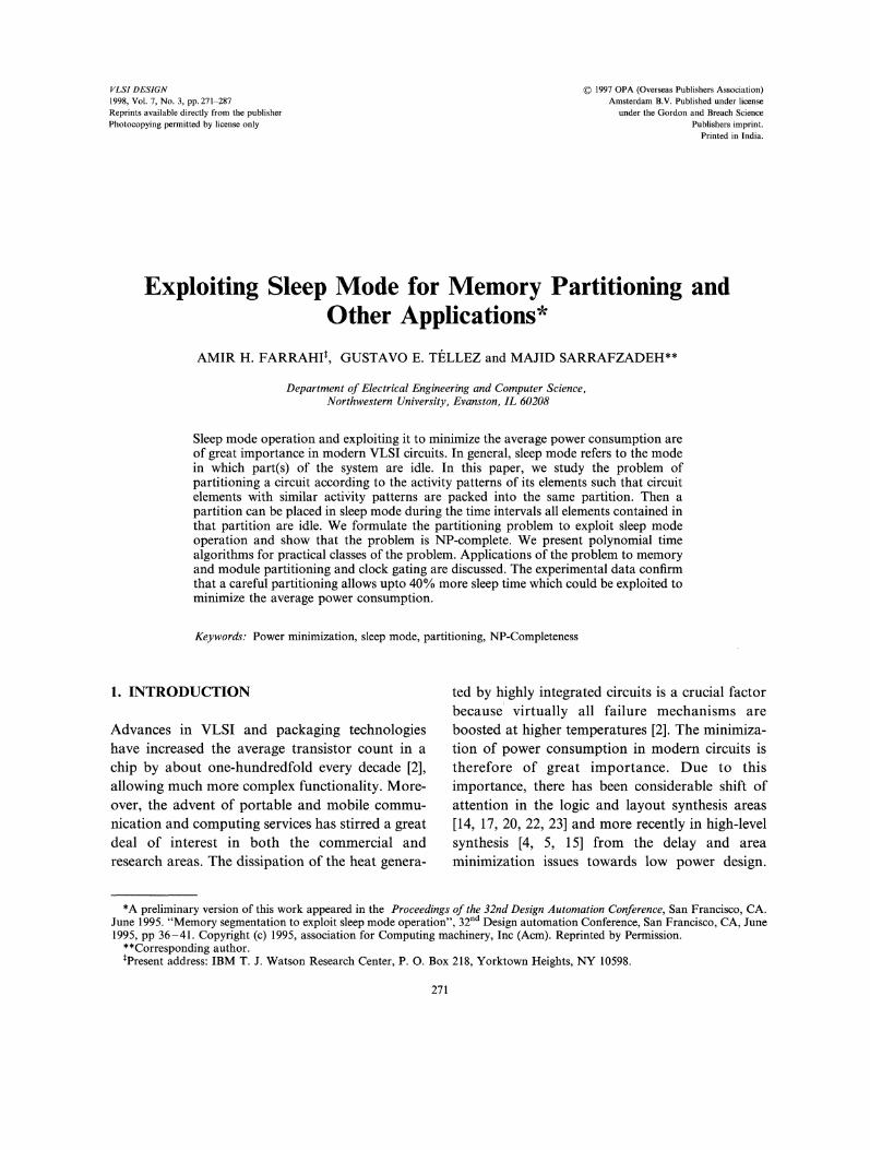
In this paper we study the partitioning problemto exploit sleep mode for power minimization indigital circuits. The general problem can be viewedas partitioning a set of circuit elements such thatthe savings in power consumption achieved byswitching each partition as a whole into sleepmode is maximized. A partition can be switchedinto sleep mode during time interval I (l, r) if allthe elements in that partition are idle during L Theset of intervals during which an element rn is idle,is referred to as the idle set of m. We present ageneral formulation for the problem and study itscomplexity. The problem finds many applicationsin low power design, e.g., the following (see Fig. 1):
memory segmentation.partitioning to power-down portions of thedesign.clock tree construction.
We assume we have synthesis (simulation-based) or statistical data on the idle. times of the
Memory ..’ ,..,segments.
".,, V" Mode |
"......... Control 1’Clock and/or refresh signals
a) Memory Segmentation
1 [ p..wer:’. --] Down ka[
P3 Control Supply
...... ............... b) Partitioning for Power DownCircuit
o..oo.oOo,Clockedelements c) Clock Tree Construction
FIGURE Circuit partitioning to exploit sleep mode opera-tion.
data items (in case of memory segmentation) orthe idle times of the modules (for the two othercases). We present a general formulation for thisproblem, propose polynomial time algorithms tosolve special classes of the problem optimally, andshow that the general problem is NP-complete.This rest of this paper is organized as follows:Section 2 presents the necessary background.Section 3 briefly describes how to obtain the idletimes for a set of memory or clocked elements in adesign. Section 4 presents the problem formula-tion. The complexity of the problem is discussed inSection 5. Exact algorithms to solve the generalproblem are presented in Section 6. Some specialclasses of the problem are discussed in Section 7and polynomial time algorithms are presented tosolve these classes. Section 8 focuses on somegeneralization of the problem. Experimental re-sults for memory segmentation are provided inSection 9, and Section 10 concludes the papersummarizing the key features of this study and
MEMORY PARTITIONING 273
provides directions for further research in thisarea.
2. BACKGROUND
There are three sources of power consumption inCMOS circuits: the charging and discharging ofcapacitive loads during transitions at gate outputs,the short circuit current which flows during outputtransitions, and the leakage current. The last twosources should be dealt with and optimized usingproper device and circuit design techniques [24],hence the design automation community hasfocused on the minimization of the first source,which is frequently referred to as the switchingpower or dynamic power. The average dynamicpower consumption for a CMOS gate g with loadcapacitance Cg is given by:
Pav(g) 0.5 Cg V2dd O (g), (1)
where D(g) and Vdd represent the transitiondensity3 of the signal at the output of g, and thevoltage of the power supply, respectively.
This suggests that a signal has a high contribu-tion to the dynamic power consumption if it haseither relatively large load capacitance or relativelyhigh transition density. And these are both trueabout the clock signal in moderately sizedsynchronous digital systems. Recent studies [1]indicate that the clock signal and memory eachconsumes somewhere between 15 to 45 percent ofthe total power in digital computers. Hence, itwould be worthwhile to study the mechanisms andapproaches through which the power consumptiondue to these sources can be optimized. Exploitingsleep mode is an attempt to do so. Consider ascenario in which the access times to a set ofdynamic memory elements are known. If we canpartition these memory elements such that for longperiods of time either of the partitions contains nodata, then we can turn off the memory refresh
circuitry for that partition during these periodsand thus reduce the power consumption. A similarpartitioning approach can be applied for clock-tree construction when the activity patterns of theclocked elements are known. The clock signaldestinations with close activity patterns should bepartitioned into the same subtree to allow maxi-mum savings in power consumption via clockgating (see Fig. 1). Clearly, there is some overheadinvolved, caused by the extra control logic neededto switch the partitions in and out of sleep modeand the amount of power that switching in and outof sleep mode will consume. This overhead ismainly dependent on the switching pattern andswitching frequency of the partitions in and outof sleep mode.To have a general formulation, we talk about
elements. Depending on the application, an ele-ment may refer to a memory element, clockedelement, or a module in the circuit. Given theactivity patterns of a set of elements, the questionis how to partition this set to maximize the savingsin power consumption achievable through sleepmode, and that how much power would thistechnique save us. We believe that there is a highpotential of savings in the power consumptionusing this technique and our paper is an attempt tostudy this problem.
3. OBTAINING IDLE SETS
In this section, we briefly describe methodologiesto obtain the activity patterns and the idle sets ofthe memory and clocked elements in our design.Availability of these activity patterns are vital forthe partitioning algorithm to be applicable.
3.1. Idle Sets for Memory Elements
Let M={ml, m2,...,mr} represent the set ofdynamic memory elements (MEs) in an applica-tion. Assume that the access sequence for each
3Average number of transitions per unit time.

274 A.H. FARRAHI et al.
ME mi E M during a whole run cycle is given as a
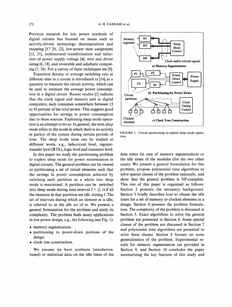
sequence of ordered pairs each of the form (ti, Ai),where ti corresponds to the access time, andAiE{.R,14/} represents the type of access, read(R), or write (W) (see Fig. 2). Given the accesssequence for all the MEs, we can use the followingrules to generate the set of intervals for each MEmi, during which mi need not be refreshed (seeFig. 2) and thus obtain the idle set for each ME.We say ME rni is idle during interval I if it need notbe refreshed during L Therefore ME mi id idle:
After its final access time,Before each write access until the closest readaccess (or the start of computation)
To obtain the access sequence for the MEs, wecan use simulation-based tools that take as inputan application program and produce statistics onthe resource utilization over time and space.
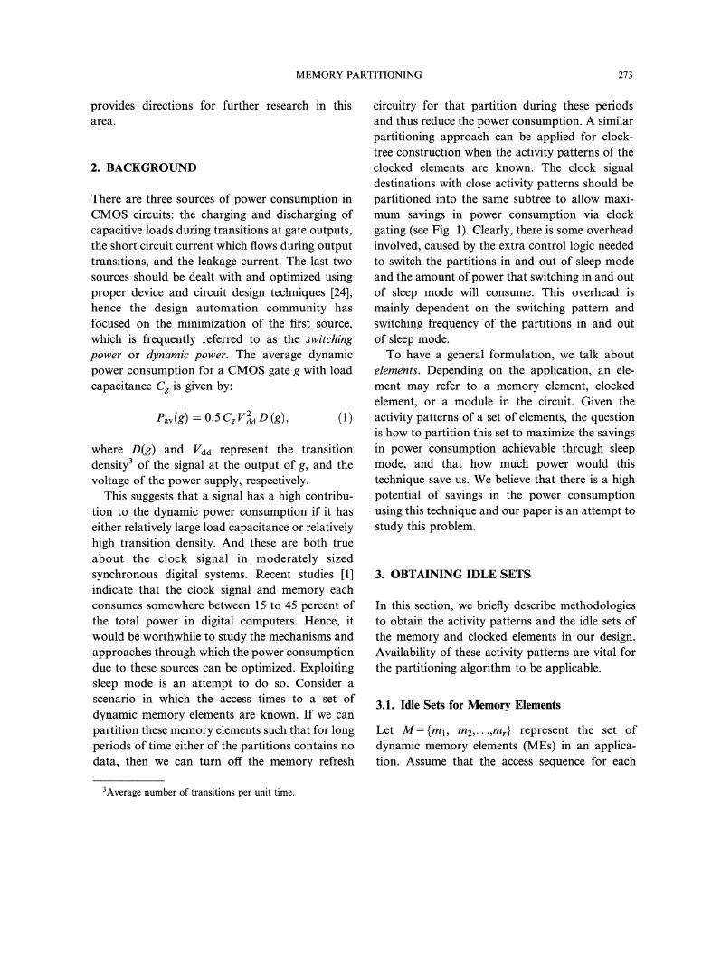
this FU during this idle time, which will reduce thepower consumption due to the clock tree.Furthermore, it guarantees that there would beno dynamic power consuming activity during thistime in A/[. From the scheduled and allocateddesign we can say that if FU A4 is assigned to acontrol step c, then it is active during c. Otherwise,it is idle during this time. This allows us togenerate the idle sets for each of the FUs in ourdesign. Figure 3 shows how to obtain the idle setsfrom a design that solves a differential equation ofthe form y" + 3zy + 3y 0 after schedulingand allocation have taken place. The designcontains the following functional units: threemultipliers M1, M2, .M3, two adders A1, A2, onesubtractor S1, and one comparator C1. The idlesets for the registers at the inputs of each FU iscomputed from the Control-Data Flow Graph(CDFG) after scheduling and allocation are done.
3.2. Idle Sets for Clocked Elements
Consider the description of a design after thescheduling and allocation steps have been per-formed. We assume that the functional units haveregisters at their input. This means that if an FUA4 is not used for a consecutive set of cycles, thenwe can gate the clock signal to the registers feeding
ml
m2
m3
m4
m5
m6
Access Sequences
N El .’-I
N2 .’-I
N3 [] [-]
N4
N5 El
N6 ------- I"l
17
Computation Time Window end
Represents read (R)
I-! Represents write (W)
Represents idle interval
CDFG:
ctr
zl
yl
M1
M2 ;-M3
Fuentional AUnits A2
Sl
C1
FIGURE 2 Computing idle sets for memory from thememory access sequence.
FIGURE 3 Computing the idle sets for a scheduled andallocated design.
MEMORY PARTITIONING 275
These idle sets are shown at the bottom next to thenames of their corresponding FUs. Note that themultiplier units take 2 control steps to execute.
However, they are clocked only during the firstof the two control steps. This is assuming that themultiplier units are purely combinational, andrequire no clock signal during their operation. Inother contexts, the multipliers (or other multi-stepFUs) may need to be clocked during their wholeexecution cycle. The idle times should be com-puted according to these requirements.
4. FORMULATION OF THE PROBLEM
Consider a set M {ml, m,..., mr} of elements.We say that element m is idle during time intervalI (l, r), < r, if m can be switched into sleepmode during I. We say that interval I (1, r)contains point p, or p is contained in I if <p < r.
Intervals I1 (/1, rl) and 12 (12, r2) are non-
overlapping if ll >_ r2 or 12 _> rl. A set of intervals arenon-overlapping if they are pairwise non-over-lapping. The idle set Nm of m consists of a set ofnon-overlapping intervals or NISs (Non-overlap-ping Interval Sets) during all of which m is idle. Weassume that the idle sets of elements in M aregiven as a set S={N1,N2,...,Nr}, where Ni-{Iil, Ii2,..., Iini} is the idle set of mi (see Fig. 4).The notation () denotes an empty interval. Givenintervals I1--(/1,rl) and I2- (12, r2), we say I1covers I2 if either ll _< 12, r2 _< rl, or I2 0 (that is,all intervals cover the empty interval). The lengthL(I) of an interval I (l, r) is defined as thequantity r (or 0 if I 0). The intersection oftwo intervals I1 and I, denoted as I1 A I, isdefined as the longest interval covered by both I1and I2 (or empty if the two intervals do notoverlap). The intersection of more than twointervals is defined similarly. It is easy to see thatthe intersection of more than two intervals iscommutative, hence no parentheses are needed.The intersection of two NISs N1- {I11, I12,...,Inl} and N {I,I2, Izn2}, denoted as N1A Ne, is defined as the NIS formed of the non-
empty pairwise intersections of the intervals onepicked from N1 and the other picked from N2,that is"
N1 A N2 {I=/ A IlI N,I2 N2,
I1 A h =/= ()}(2)
The intersection of more than two NISs isdefined similarly. As for the intervals, the inter-section of multiple NISs is a commutative opera-tion and parentheses can be omitted withoutcausing ambiguity. Given NISs N1, N, we sayN1 covers N2 if N1 A N2 N2. The endpoint set ENof a NIS N is defined as the set of endpoints of theintervals in N, that is: EN {p[ p: (P, q) N or(q, p) N}. The duration D(N) of a NIS N {I1,I2,..., I} is defined as the sum of the lengths ofthe intervals contained in it, that is: D(N) i=L(Ii). Given a set S {NI, N.,...,N} of NISs,the internal-intersection A(S) of S is defined as theintersection of all the NISs in S, that is:
A(S) /NiGS Ui (3)
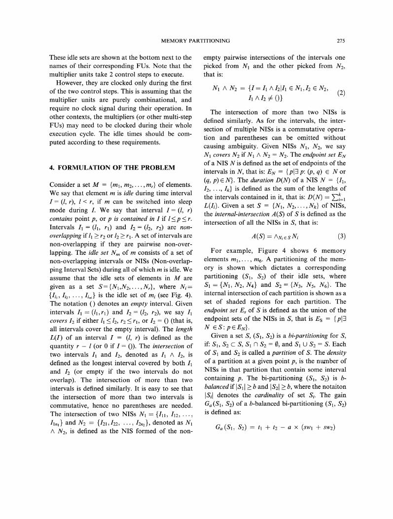
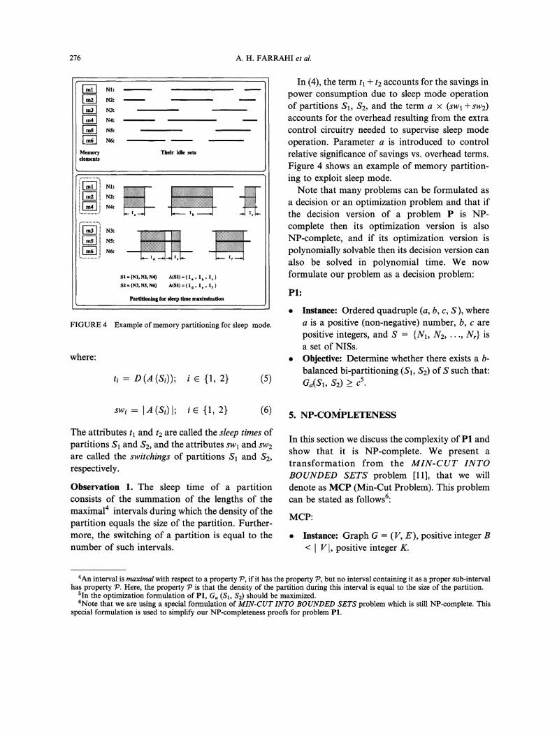
For example, Figure 4 shows 6 memoryelements ml,..., m6. A partitioning of the mem-ory is shown which dictates a correspondingpartitioning (S1, $2) of their idle sets, where
S1 {N, N2, N4} and Sa {N3, N5, N6}. Theinternal intersection of each partition is shown as aset of shaded regions for each partition. Theendpoint set E of S is defined as the union of theendpoint sets of the NISs in S, that is EsN ES: pEEN}.
Given a set S, (S1, S:) is a hi-partitioning for S,if: S, Sz c S, $1 fq $2 , and S1 U $2 S. Eachof S1 and $2 is called a partition of S. The densityof a partition at a given point p, is the nuanber ofNISs in that partition that contain some intervalcontaining p. The bi-partitioning (S1, $2) is b-balanced if ISl[ b and ISzl _> b, where the notaiton
Isil denotes the cardinality of set Si. The gainGa (S1, $2) of a b-balanced bi-partitioning ($1, $2)is defined as:
Ga (S, S2) tl + tg. a (sw1 -+- sw2)
276 A.H. FARRAHI et al.
’ NI:
N2:
’ N3:
[ N4:
N6:
Memoryelements
Their ldl sets
NI:
N2:
N4:
N3:
N$:
N6:
|NI, N2, N4} A(Sl) I,, b, IS2-|N3,N$,N6] A(SI)=(I I,, if}
Partitioning for sleep time maximization
FIGURE 4 Example of memory partitioning for sleep mode.
where:
ti D(A(Si)); {1, 2) (5)
In (4), the term tl + t2 accounts for the savings inpower consumption due to sleep mode operationof partitions S1, $2, and the term a x (SWl + sw2)accounts for the overhead resulting from the extracontrol circuitry needed to supervise sleep modeoperation. Parameter a is introduced to controlrelative significance of savings vs. overhead terms.Figure 4 shows an example of memory partition-ing to exploit sleep mode.Note that many problems can be formulated as
a decision or an optimization problem and that ifthe decision version of a problem P is NP-complete then its optimization version is alsoNP-complete, and if its optimization version ispolynomially solvable then its decision version canalso be solved in polynomial time. We nowformulate our problem as a decision problem:
PI:
Instance: Ordered quadruple (a, b, c, S), wherea is a positive (non-negative) number, b, c arepositive integers, and S {N1, N2,..., Nr} isa set of NISs.Objective: Determine whether there exists a b-balanced bi-partitioning (S1, $2) of S such that:Ga(S1, S2) 5.
w, a (sD I; {1, 2} (6)
The attributes tl and t2 are called the sleep times ofpartitions S1 and $2, and the attributes SWl and sw2are called the switchings of partitions S1 and $2,respectively.
Observation 1. The sleep time of a partitionconsists of the summation of the lengths of themaximal4 intervals during which the density of thepartition equals the size of the partition. Further-more, the switching of a partition is equal to thenumber of such intervals.
5. NP-CONPLETENESS
In this section we discuss the complexity of P1 andshow that it is NP-complete. We present atransformation from the MIN-CUT INTOBOUNDED SETS problem [11], that we willdenote as MCP (Min-Cut Problem). This problemcan be stated as follows6:
MCP:
Instance: Graph G (V, E), positive integer B< V I, positive integer K.
4An interval is maximal with respect to a property P, if it has the property P, but no interval containing it as a proper sub-intervalhas property 79. Here, the property 79 is that the density of the partition during this interval is equal to the size of the partition.
5in the optimization formulation of P1, Ga (S1, $2) should be maximized.6Note that we are using a special formulation of MIN-CUT INTO BOUNDED SETS problem which is still NP-complete. This
special formulation is used to simplify our NP-completeness proofs for problem P1.
MEMORY PARTITIONING 277
Objective: Determine whether there exists a B-balanced bi-partitioning (V1, V2) of V suchthat:
E w(u, v) < Ku V,v V2
where,
f 0 if (u,v)Ew(u, v)
if (u,v) EE
That is, the size of each partition is lowerbounded by B, and the number of edges in Ewith one endpoint in V1 and the other endpointin V2 is no more than K. We will refer to thenumber of such edges as the cost of the bi-partitioning and denote it as C (V1, V2).
Given a partitioning (V1, V2) of V, we define anattribute ci for each edge ei (vii ,vi2) in E, referredto as the cost of that edge under partitioning(V, V2), as follows:
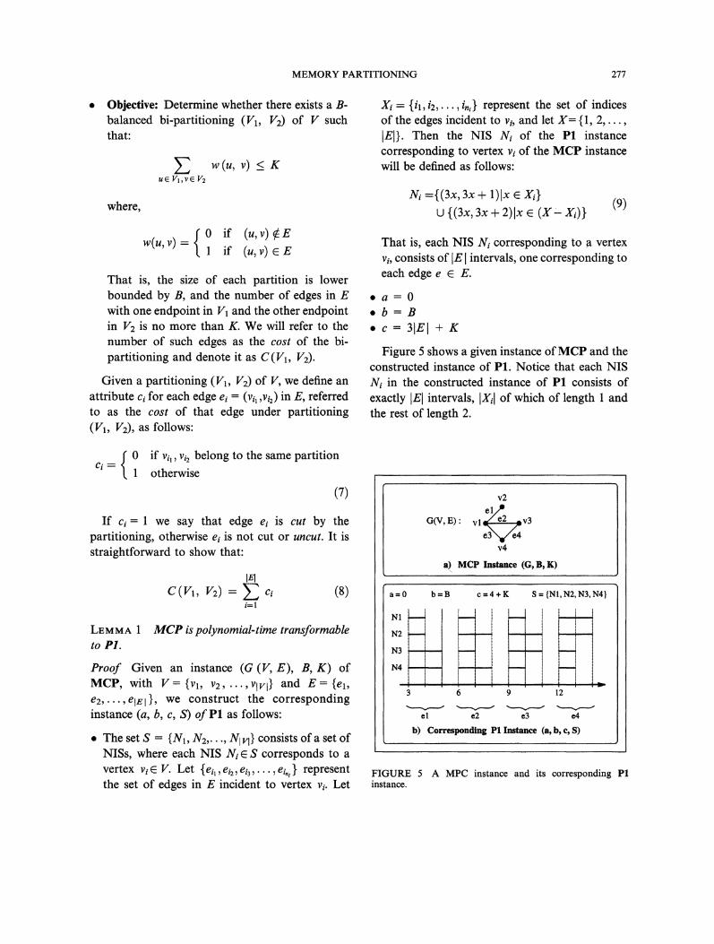
X {i,i,...,in,} represent the set of indicesof the edges incident to vi, and let X= {1, 2,...,IEI}. Then the NIS N of the P1 instancecorresponding to vertex v of the MCP instancewill be defined as follows:
Ni---{(3x, 3x + 1)Ix{(3x, 3x + )lx e (Jr
(9)
That is, each NIS N corresponding to a vertexv, consists of IEI intervals, one corresponding toeach edge e E E.
a=0b=B
.c=31El+ g
Figure 5 shows a given instance ofMCP and theconstructed instance of P1. Notice that each NISN in the constructed instance of P1 consists ofexactly IEI intervals, IXI of which of length andthe rest of length 2.
0Ci
if vil, vi2 belong to the same partitionotherwise
(7)
If c= 1 we say that edge ei is cut by thepartitioning, otherwise eg is not cut or uncut. It isstraightforward to show that:
i=1
LEMMA 1to P1.
MCP is polynomial-time transformable
Proof Given an instance (G (V, E), B, K) ofMCP, with V= {V1, V2, ,VIVI} and E {el,e2,...,ele I}, we construct the correspondinginstance (a, b, c, S) of Pl as follows:
The set S {N1, N2,..., Nit} consists of a set ofNlSs, where each NIS N S corresponds to avertex v V. Let {ei, el2, eia,..., %} representthe set of edges in E incident to vertex v. Let
G(V,E)" vl e2 v3
v4
a) MCP Instance (G, B, K)
a=0 b=B c=4+K
N1
N2
N3
N4
3 6 9
el e2 e3
S {NI, N2, N3, N4
12
4
b) Corresponding P1 Instance (a, b, c, S)
FIGURE 5 A MPC instance and its corresponding P1instance.
278 A.H. FARRAHI et al.
Main Idea: In the construction of the PI instance,the following issues have been taken into account:
A partitioning (V1, V2) of vertices in the MCPinstance should correspond to the partitioning(S1, $2) of the corresponding NISs in the PIinstance and vice versa, e.g., the partitioning({Vl, 113} {12, V4}) of V corresponds to thepartitioning ({N, N3}, {Nz, N4}) of S.The gain Ga of the partitioning (S1, Sz) of S inthe P1 instance should be a decreasing functionof the cost C of the corresponding partitioning(V, V) of V in the MCP instance.
Having established such relationship betweenthe MCP and PI instances, it is easy to see that thecost of a partition in the MCP instance isminimized if and only if the gain of the corres-ponding partitioning of the P1 instance is max-imized. Then by selecting the. parameters a, b, cproperly, we can show that the answer to the MCPinstance is YES if and only if the answer to theconstructed P1 instance in YES. The followingelaborates further on these arguments:
General Properties: As it is shown in Figure 5, thePI instance is constructed such that correspondingto each edge ei (vj, Vk) in the MCP instance thereare IV intervals, one in each of the NISs, and theyare all overlapping. Let 2i (Iil,Ii2,...,Iilvl}represent the set of these intervals, where lip isthe interval corresponding to ei=(vj, vk) in Np.Among these intervals, I/ and Iik, the two in Nj,Nk (NISs corresponding to vertices v, vk, the twoends of edge e;), extend from. 3i to 3i + 1, and therest extend from 3i to 3i+2. Consider a bi-partitioning ($1, $2) of S. Note that thispartitioning induces a corresponding partitioning(Zil ,Zi2 on each of the I’s. We can make thefollowing observations from the construction ofPI instance:
Observation 2. Two intervals in the constructedP1 instance corresponding to two distinct edges e,ej of MCP instance do not overlap each other.
Observation 3. Since a 0, we have: Ga(S1, $2)t+t2.
From Observation 2 and the definition of t andt2, it becomes clear that t and t2 can each becomputed as the summation of IE] terms. Each ofthese IEI terms corresponds to the contribution ofthe intervals corresponding to one of the edges inthe MCP instance. Therefore we can write:
tl tl, (10)i=1
tE-- yt2, (11)i=1
Ga(S1, S1) Z(tl + t2) (12)i=l
where:
tl, L(AIosz,, I); Vi E {1,2,..., IEI (14)
t2, L(AIsZIb); Vi {1,2,..., IEI} (5)
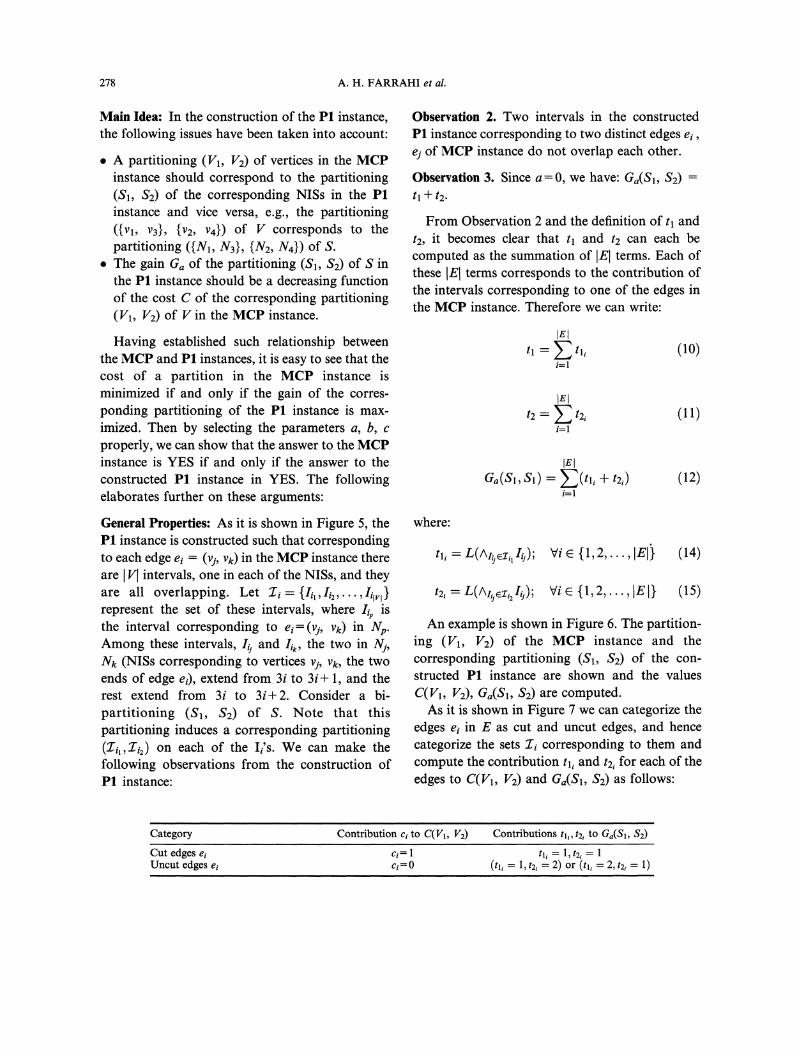
An example is shown in Figure 6. The partition-ing (V1, Vz) of the MCP instance and thecorresponding partitioning ($1, Sz) of the con-structed PI instance are shown and the valuesC(V1, V2) Ga(S1, S2) are computed.As it is shown in Figure 7 we can categorize the
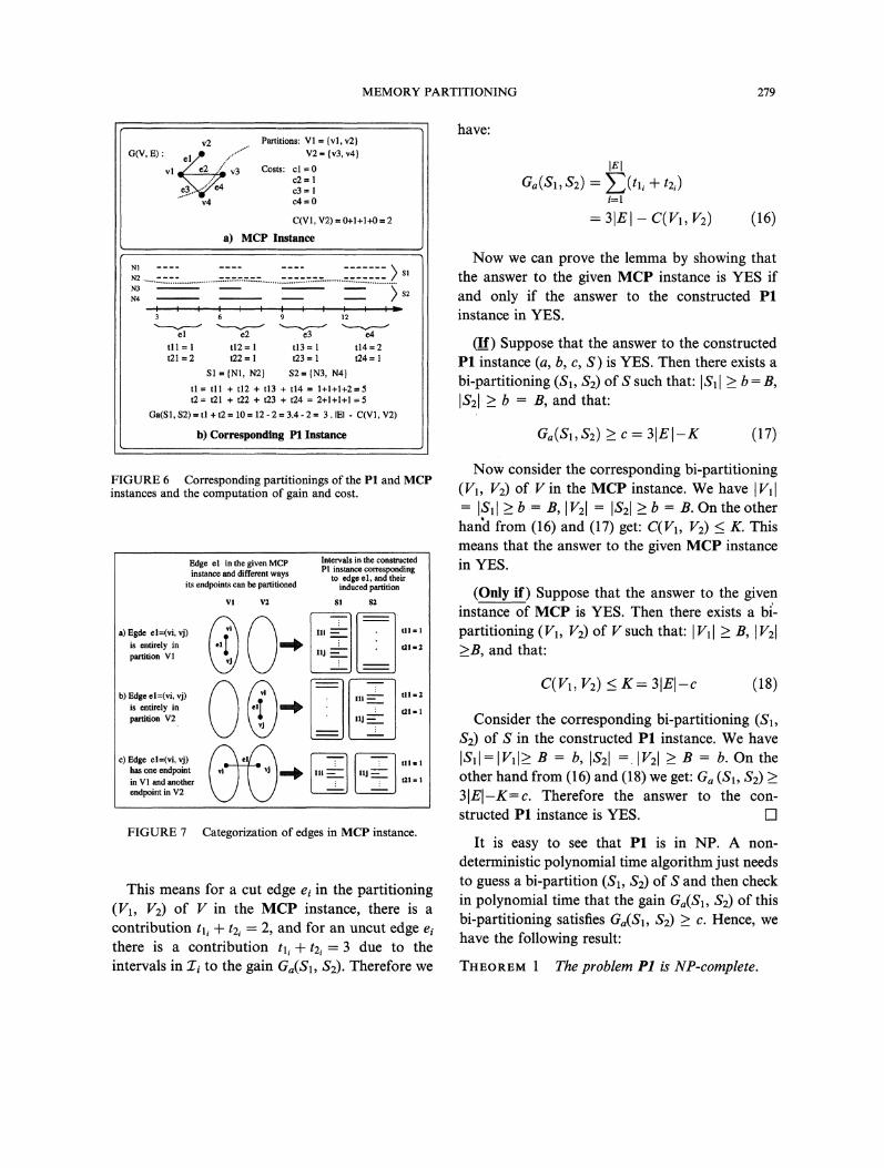
edges e in E as cut and uncut edges, and hencecategorize the sets 2 corresponding to them andcompute the contribution tl and t2 for each of theedges to C(Vx, V2) and Ga(S, $2) as follows:
Category Contribution ci to C(VI, V2) Contributions tl,, t2, to Ga(S1, $2)
Cut edges eiUncut edges e
ci tl 1, t2ici=O (tb 1, t2, 2) or (tl, 2, t2 1)
MEMORY PARTITIONING 279
v2 Partitions: V1 {vl, v2}G(V, E) el/)..el......... V2 {v3, v4}
vl v3 Costs: cl=0",, ...’V- c2--e..3.e4.. e3
v4 c4"-0
C(V1, V2) 0+1+1+0 2
a) MCP Instance
N2$1
N3 \
N4 2 $2
’I ’,12
el e2 e3 e4tll= t12= t13 t14=2t21 2 t22 t23 t24
Sl IN1, N2} S2-- IN3, N41tl-- tll + t12 + t13 + t14 1+1+1+2=5t2-- t21 + t22 + t23 + t24 2+I+1+1
Ga(S1, $2) tl + t2 10 12 2 3.4 3. IEI C(VI, V2)
b) Corresponding P1 Instance
have:
Ga(S1, S2)--- -(tli -[-i=1
3IEI C(V1, Vz) (16)
Now we can prove the lemma by showing thatthe answer to the given MCP instance is YES ifand only if the answer to the constructed P1instance in YES.
(If) Suppose that the answer to the constructedP1 instance (a, b, c, S) is YES. Then there exists abi-partitioning ($1, $2) of S such that: ISll _> b- B,IS2I. > b B, and that:
aa(Sl,S2) c--31EI-K (17)
FIGURE 6 Corresponding partitionings of the P1 and MCPinstances and the computation of gain and cost.
Edge el in the given MCP Intervals in the constructed
instance and different ways PI instance eorrespondingto edge el, and their
its endpoint be partitioned induced partition
VI V2 SI $2
is entirely in tZl =2partition Vl L_J._is entirely in mm t21partition V2 [llJ----=-..has one endpoint Illin VI and another tlt
endpoint in V2
FIGURE 7 Categorization of edges in MCP instance.
This means for a cut edge ei in the partitioning(V1, V2) of V in the MCP instance, there is acontribution tl, + t2, 2, and for an uncut edge eithere is a contribution tli + t2i 3 due to theintervals in Z to the gain Ga(S1, $2). Therefore we
Now consider the corresponding bi-partitioning(V1, V2) of V in the MCP instance. We have IVll
ISll > b B, V2l [S2l > b B. On the otherhand from (16) and (17) get: C(V1, V2) < K. Thismeans that the answer to the given MCP instancein YES.
(Only if) Suppose that the answer to the giveninstance of MCP is YES. Then there exists a bi’-partitioning (V1, V2) of V such that: IVll > B, Iv21>B, and that:
c(v, v) <_ K- 31EI-c (18)
Consider the corresponding bi-partitioning (S1,$2) of S in the constructed PI instance. We haveISll:lVll_> B b, IS21 -..IV21 _> B- b. On theother hand from (16) and (18) we get: Ga (S1, $2)3IEI-K=c. Therefore the answer to the con-structed P1 instance is YES.
It is easy to see that P1 is in NP. A non-deterministic polynomial time algorithm just needsto guess a bi-partition ($1, $2) of S and then checkin polynomial time that the gain Ga(S1, $2) of thisbi-partitioning satisfies Ga(S1, $2) _> C. Hence, wehave the following result:
THEOREM The problem P1 is NP-complete.
280 A.H. FARRAHI et al,
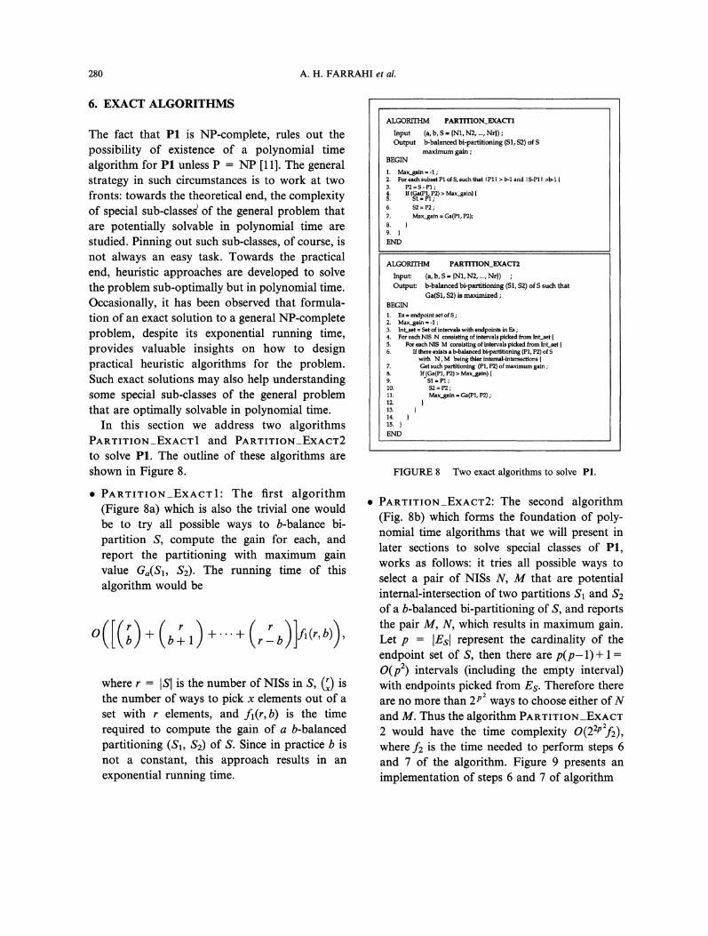
6. EXACT ALGORITHMS
The fact that PI is NP-complete, rules out thepossibility of existence of a polynomial timealgorithm for P1 unless P NP [11]. The generalstrategy in such circumstances is to work at twofronts: towards the theoretical end, the complexityof special sub-classes of the general problem thatare potentially solvable in polynomial time arestudied. Pinning out such sub-classes, of course, isnot always an easy task. Towards the practical.end, heuristic approaches are developed to solvethe problem sub-optimally but in polynomial time.Occasionally, it has been observed that formula-tion of an exact solution to a general NP-completeproblem, despite its exponential running time,provides valuable insights on how to designpractical heuristic algorithms for the problem.Such exact solutions may also help understandingsome special sub-classes of the general problemthat are optimally solvable in polynomial time.
In this section we address two algorithmsPARTITION_EXACT1 and PARTITION_EXACT2
to solve P1. The outline of these algorithms areshown in Figure 8.
PARTITION_EXACT1: The first algorithm(Figure 8a) which is also the trivial one wouldbe to try all possible ways to b-balance bi-partition S, compute the gain for each, andreport the partitioning with maximum gainvalue Ga(S1, $2). The running time of thisalgorithm would be
O(I(;)-+-(b-1) +’"+ (rrb)]fl(r’b))where r ISl is the number of NISs in S, () isthe number of ways to pick x elements out of aset with r elements, and fl(r,b) is the timerequired to compute the gain of a b-balancedpartitioning (S1, $2) of S. Since in practice b isnot a constant, this approach results in anexponential running time.
ALGORrrI PARTITION_EXACT1
Input (a, b, S {N1, N2 Nr})Output b-balanced bi-partitioning (S1, S2) of S
maximum gainBEGIN
1. Max_gain -12. For each subset P1 of S, auch that P1 b-1 and S-P1 >b-13. P2 P1
541 If (Ga(P1s11;P2) MaxLgain}
6. $2=P2;
7. Max..gain Ga(PI, P2);8.9.
END
ALGORITHM PARTITION_EXACT2
Input: (a, b, S {N1, N2 Nr))Output: b-balanced bi-partitioning ($1, $2) of S such that
Ga(S1, $2) is maximized;BEGIN1. Ea endpoint act of2. Max_gain -13. Int_aet Set of intervals with endpoint in Ea;4. For each NIS N consisting of intervals picked from Int..set5. Pot each NIS M consisting of intervals picked from Int_aet6. If there exist b-bManced bi-partitioning (P1, P2) of
with N, M being thief internal-intersections7. Get such partitioning (P1, P2) of maximum gain8. If.(Ga(P1, P2) Max_gain)9. $1 P1I0. S2=P2;11. Max_gain Ga(P1, P2)2.13.14.15.
END
FIGURE 8 Two exact algorithms to solve P1.
PARTITION_EXACT2: The second algorithm(Fig. 8b) which forms the foundation of poly-nomial time algorithms that we will present inlater sections to solve special classes of P1,works as follows: it tries all possible ways toselect a pair of NISs N, M that are potentialinternal-intersection of two partitions $1 and $2of a b-balanced bi-partitioning of S, and reportsthe pair M, N, which results in maximum gain.Let p [Es[ represent the cardinality of theendpoint set of S, then there are p(p-1)+ 1O(p2) intervals (including the empty interval)with endpoints picked from Es. Therefore thereare no more than 2p2 ways to choose either ofNand M. Thus the algorithm PARWlWION_EXACW2 would have the time complexity O(22p:f2),where f2 is the time needed to perform steps 6and 7 of the algorithm. Figure 9 presents animplementation of steps 6 and 7 of algorithm
MEMORY PARTITIONING 281
P1 {Ni e S U ^ NV N Pl M ^ Ni M};If (IPI < ) (IPal + IPI < 2b)
Goto next iteration of loop nt step 5;
aP {N PxlM A N M}(laPI + levi b){AP A subt of P with size p, where(b IPI) 5 (IPI b);P P p;P P U P;
FIGURE 9 Implementation of steps 6, 7 of Algorithm_Ex-act2.
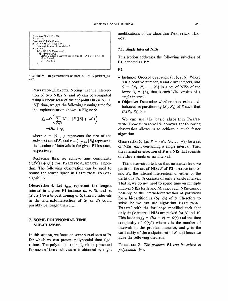
PARTITION_EXACT2. Noting that the intersec-tion of two NISs N and Nj. can be computedusing a linear scan of the endpoints in O(INi +INj.I) time, we get the following running time forthe implementation shown in Figure 9:
f2 --0( Z[Ni] + [SI([N[ + [M[))NeS
+where s IS 1, p represents the size of theendpoint set of S, and r -]uizs [Ni[ representsthe number of intervals in the given P1 instance,respectively.
Replacing this, we achieve time complexityO(22p2 (S -+- rp)) for PARTITION_EXACT2 algori-thm. The following observation can be used tobound the search space in PARTITION_EXACT2
algorithm:
Observation 4. Let /max represent the longestinterval in a given P1 instance (a, b, S), and let(S1, $2) be a bi-partitioning of S, then no intervalsin the internal-intersection of S1 or $2 couldpossibly be longer than/max.
7. SOME POLYNOMIAL TIMESUB-CLASSES
In this section, we focus on some sub-classes of PIfor which we can present polynomial time algo-rithms. The polynomial time algorithm preentedfor each of these sub-classes is obtained by slight
modifications of the algorithm PARTITION _Ex-
ACT2.
7.1. Single Interval NISs
This section addresses the following sub-class ofP1, denoted as P2:
P2:
Instance: Ordered quadruple (a, b, c, S). Wherea is a positive number, b and c are integers, andS {N1, N2,..., Nr} is a set of NISs of theform: Ni {Ii}, that is each NIS consists of asingle interval.Objective: Determine whether there exists a b-balanced bi-partitioning (S1, $2) of S such thatGa(S1, S2) c.
We can use the basic algorithm PARTI-TION_EXACT2 to solve P2, however, the followingobservation allows us to achieve a much fasteralgorithm.
Observation 5. Let P {N1, N2,..., Nk} be a setof NISs, each containing a single interval. Thenthe internal-intersection of P is a NIS that consistsof either a single or no interval.
This observation tells us that no matter how wepartition the set of NISs S of P2 instance into S1and $2, the internal-intersection of either of thepartitions $1, $2 consists of only a single interval.That is, we do not need to spend time on multipleinterval NISs for N and M, since such NISs cannotpossibly be the internal-intersection of partitionsfor a bi-partitioning ($1, $2) of S. Therefore tosolve P2 we can use algorithm PARTITION_
EXACT2 with the for loops modified such thatonly single interval NISs.are picked for N and M.This leads to f2 O(s + r) O(s) and the timecomplexity of O(sp4) where s is the number ofintervals in the problem instance, and p is thecardinality of the endpoint set of S, and hence wehave the following theorem:
THEOREM 2 The problem P2 can be solved inpolynomial time.
282 A.H. FARRAHI et al.
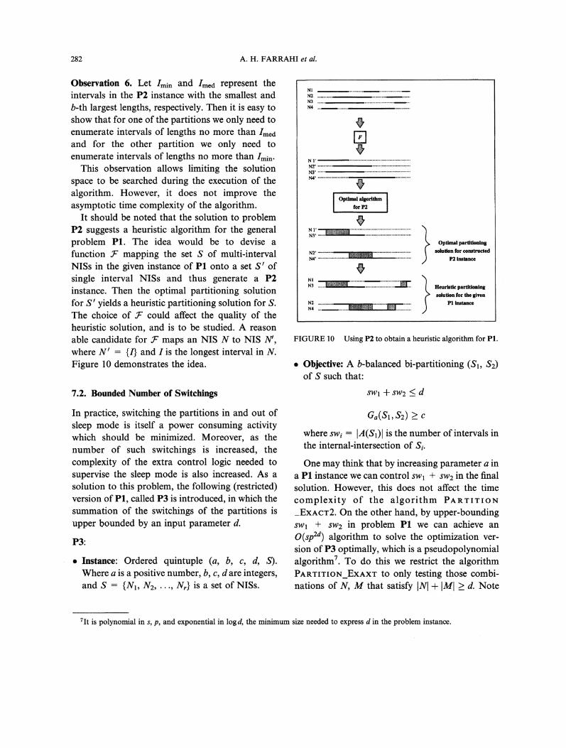
Observation 6. Let /min and ImCd represent theintervals in the P2 instance with the smallest andb-th largest lengths, respectively. Then it is easy toshow that for one of the partitions we only need toenumerate intervals of lengths no more than ImCdand for the other partition we only need toenumerate intervals of lengths no more than Imin.
This observation allows limiting the solutionspace to be searched during the execution of thealgorithm. However, it does not improve theasymptotic time complexity of the algorithm.
It should be noted that the solution to problemP2 suggests a heuristic algorithm for the generalproblem PI. The idea would be to devise afunction " mapping the set S of multi-intervalNISs in the given instance of P1 onto a set S’ ofsingle interval NISs and thus generate a P2instance. Then the optimal partitioning solutionfor S’ yields a heuristic partitioning solution for S.The choice of could affect the quality of theheuristic solution, and is to be studied. A reasonable candidate for - maps an NIS N to NIS N’,where N’ {/} and I is the longest interval in N.Figure 10 demonstrates the idea.
7.2. Bounded Number of Switchings
In practice, switching the partitions in and out ofsleep mode is itself a power consuming activitywhich should be minimized. Moreover, as thenumber of such switchings is increased, thecomplexity of the extra control logic needed tosupervise the sleep mode is also increased. As asolution to this problem, the following (restricted)version of P1, called P3 is introduced, in which thesummation of the switchings of the partitions isupper bounded by an input parameter d.
P3:
Instance: Ordered quintuple (a, b, c, d, S).Where a is a positive number, b, c, d are integers,and S {N1, N2,..., Nr} is a set of NISs.
NIN2
N2’NYN4’
Optimal algoritinnfor P2
N3’
N2 t
NI
Optimal partitioning
solution for constructedP2 instance
Heuristic partitioningsolution for the given
P1 instance
FIGURE 10 Using P2 to obtain a heuristic algorithm for P1.
Objective: A b-balanced bi-partitioning (S1, $2)of S such that:
SW1 + $W2 d
aa(Sl,S2) c
where swi IA(S1)l is the number of intervals inthe internal-intersection of Si.
One may think that by increasing parameter a ina P1 instance we can control sw "+- SW2 in the finalsolution. However, this does not affect the timecomplexity of the algorithm PARTITION_EXACT2. On the other hand, by upper-boundingSWl + sw2 in problem PI. we can achieve anO(sp2d) algorithm to solve the optimization ver-sion of P3 optimally, which is a pseudopolynomialalgorithm7. To do this we restrict the algorithmPARTITION_EXAXT to only testing those combi-nations of N, M that satisfy INI + IM[ >_ d. Note
7It is polynomial in s, p, and exponential in log d, the minimum size needed to express d in the problem instance.
MEMORY PARTITIONING 283
that INI--SW1 and IMI--SW2. The following theo-rem is an immediate result:
THEOREM 3 The problem P3 can be solved in(pseudo)polynomial time.
8. GENERALIZATION
In this section we briefly mention a couple of thegeneralizations ofP1 (and its counterparts P2, P3).This is intended to suggest that the basic formula-tion is easily adaptable to cover a broader range ofoptimization problems. We discuss two general-izations: the multi-way partitioning, and theweighted partitioning. Note that we could also havemulti-way partitioning and weighted combined.
Weighted Partitioning: This version of theproblem is applicable in circumstances whereonly statistical analysis is possible to obtain theidle times for each element. In such cases there isa weight wi associated with each interval Ii. Theweight of an interval can represent the prob-ability that the corresponding element is idleduring that interval. The weighted version isalso useful to model a circuit where differentsub-circuits have different power attributes dueto the fact that they result in various savings inpower consumption even if they are switchedinto sleep mode for the same period of time. Inthat case, each NIS Ni has a weight wi associatedwith it.
Multi-way Partitioning: This is a straightfor-ward generalization. To solve this problem wecan either perform a recursive application of thealgorithms presented for the corresponding bi-partitioning problem, or enumerating the po-tential internal-intersection for each of thepartitions using rn nested loops that wouldreplace the two nested loops in steps 4 and 5of algorithm PARTITION_EXACT2. The tradeoff is between the quality of results and therunning time of the algorithm. The recursiveapplication of bi-partitioning approach is faster,however it generates results with inferior qual-ity. Note that this problem is especially useful inpartitioning for clock tree construction tomaximize savings in power consumption byclock gating (see Fig. l c).
9. EXPERIMENTAL RESULTS
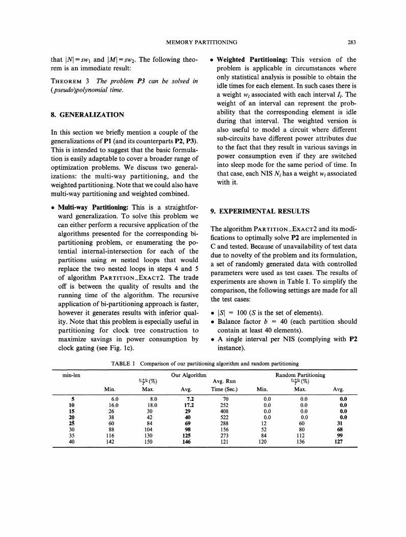
The algorithm PARTITION_EXACT2 and its modi-fications to optimally solve P2 are implemented inC and tested. Because of unavailability of test datadue to novelty of the problem and its formulation,a set of randomly generated data with controlledparameters were used as test cases. The results ofexperiments are shown in Table I. To simplify thecomparison, the following settings are made for allthe test cases:
ISI 100 (s is the set of elements).Balance factor b 40 (each partition shouldcontain at least 40 elements).A single interval per NIS (complying with P2instance).
min-len
TABLE Comparison of our partitioning algorithm and random partitioning
Our Algorithm Random Partitioning(%) Avg. Run (%)T T
Min. Max. Avg. Time (Sec.) Min. Max. Avg.
5 6.0 8.0 7.2 70 0.0 0.0 0.010 16.0 18.0 17.2 252 0.0 0.0 0.015 26 30 29 408 0.0 0.0 0.020 38 42 40 522 0.0 0.0 0.02 60 84 69 288 12 60 3130 88 104 98 156 52 80 6835 116 130 125 273 84 112 9940 142 150 146 121 120 136 127
284 A.H. FARRAHI et al.
Factor a is set to 0 (a is the penalty factor for thetotal number of switchings). This makes sensebecause the switching of either of the partitionsis in the range {0,1}, hence the sleep modecontrol circuitry will cause negligible overheadon the area or power consumption.T width of the time window 50 (SeeFig. 4).
To apply this algorithm for the general case,one can use a pre-processing step which takes asinput the idle sets of the CEs, and generates asoutput a single idle interval for each CE. Thegenerated single idle interval for a CE can simplybe the longest interval in the idle set of that CE,or it can be obtained using a more complicatedstrategy. The parameter min-len shows the lengthof the shortest interval in each problem instance.For each value of min-len, 10 random inputs aregenerated and tested with the algorithm. Theminimum, maximum and average values for theratio (tl + t2)/T resuited from our partitioningalgorithm and from a random partitioning algo-rithm are shown, where and t2 are theexploitable sleep time of the partitions in theresulting bi-partitioning. The higher this ratio is,the more the savings in power consumption wouldbe if we place the corresponding partitions insleep mode. Note that if we don’t consider the idletimes in a partitioning scheme (as it has been doneso far) the result is essentially equivalent to arandom partitioning. However, by partitioningthe set of elements according to their idle times wecan maximize ratio (tl + t2)/T, and minimize thepower consumption by exploiting sleep mode. Itcan be observed that as the length of theminimum idle times (min-len) is increased to coverthe whole time window, the results get closer.Note that since the computation window haswidth T 50, practical range for min-len is 5 to25. These cases are shown in bold face in the firstcolumn in Table I. In such cases, our algorithmproduces superior results, with an average of 7 to40% more sleep time, compared to randompartitioning.
10. DISCUSSION AND CONCLUSION
In this paper we studied the circuit partitioningproblem to exploit sleep mode operation forminimization of the average power consumption.The motivation is to de-activate the memoryrefresh circuitry, apply power down or just disablethe clock signals during the inactive periods ofoperation of corresponding circuit elements. Theidea is to partition the set of elements such that theelements with close activity patterns are groupedinto the same partition so that each partition canbe switched into sleep mode during the timeintervals all of its elements are idle. We formulatedthe problem and showed that it is NP-complete.We also discussed some special classes of theproblem which are solvable in polynomial time.Experiments were conducted to show the effec-tiveness of the presented algorithms. The results ofexperiments show possibility of significant savingsin power consumption if the sleep mode isexploited properly. Recently, a more realistic setof experiments have been reported in [9] formemory segmentation on a number of DSP andnumerical applications, with considerable reduc-tion on the estimated power consumption of thememory unit, using an iterative improvementpartitioning technique. To obtain the idle sets formemory elements in the work reported in [9] theapplications were run on an emulator with aprofiling tool that kept track of different resourceutilizations over time and space. The idle sets werethen calculated using an idea similar to the onementioned in Section 3.1 from the access sequenceprovided by the profiling tool. Further work ongated clock tree design have been reported in[3,19]. The following provides directions forfurther research in this area:
Improving the time complexity of the algo-rithms. Although the algorithms presented forspecial cases P2 and P3 are polynomial timealgorithms, the growth rate of the running timewith problem size limits the applicability of thisapproach.
MEMORY PARTITIONING 285
Having shown that sleep mode and its exploita-tion could lower the power consumption, givesrise to new problems in high level synthesis, thatis, how to perform the scheduling and allocationtasks such that potential savings in powerconsumption achievable by exploiting sleepmode operation is maximized. It is noteworthythat the register allocation step in high-levelsynthesis tends to minimize the sleep time of theregisters in order to reduce the required numberof registers in the design. This brings up thetrade off issue between area and power con-sumption in the high-level synthesis, which callsfor further investigation.We mentioned earlier that using a mappingfunction F to obtain single interval NISs frommulti-interval NISs in S, we can construct a P2instance from a given P1 instance. The con-structed P2 instance can then be solved opti-mally to lead to a heuristic partitioning solutionfor our original PI instance. Further theoreticaland experimental studies can be pursued toidentify suitable choices for the mapping func-tion F.It would be worthwhile to devise heuristicsbased on which to perform the partitioning sub-optimally, but fast. This could be of use as adesign aid for low power design to provide aquick feedback to the designer on how thedesign modifications or decisions made at higherlevels would affect the sleep times of thepartitions.The geometric flavor of the problem demandsfor carefully designed algorithms that exploitthe geometric features of the problem to achievegood solutions. Hence it is worthwhile to studythis problem from a geometric viewpoint insearch of fast approximation or heuristic algo-rithms for the general or special classes of theproblem.Another interesting problem is whether or notP1 can be formulated as a (hyper)graphparti,tioning or in general any (hyper)graphproblem at all. Our attempts indicate that sucha formulation is unlikely to exist although we
have no formal proof to present for it. Furtherresearch is in order to show whether or not suchformulation is possible. In the case of positiveanswer, the existing algorithms for the (hyper)-graph formulation can be applied to solve P1.As PI is formulated as a set partitioningalgorithm, it is nice to see how well the existingheuristics for MCP, e.g., Kernighan-Lin [13],Fiduccia-Mattheyses [10], Ratio-Cut [25], etc.,can be modified to operate on P1 instances, howfast they can be implemented, and how well theyperform.A crucial assumption in this paper was theavailability of the activity patterns (idle times) asinput to our problem. It is of particular interestto categorize the designs for which such patternscan be generated efficiently. Furthermore, incases where such patterns may not be generatedas a set of exact idle sets, statistical approachescould be employed to generate some weightedversion of the idle sets in which the weightscould represent the probabilities of being idleduring different periods. It is therefore worth-while to formulate and study the weightedversion of the problem.A generalization of the problem would be toallow multi-way partitioning, and perhaps tocompute the optimal number of partitions aswell as the contents of each partition.It is also useful to investigate other areas inwhich problem (P1) could find applications.
Acknowledgement
This work has been supported in part by theNational Science Foundation under grant MIP9207267.
References[1] In International Workshop on Low Power Design, April
1994.[2] Bakoglu, H. B. (1990). "Circuits, Interconnections, and
Packagingfor VLSI". Addison-Wesley Publishing Co.[3] Benini, L., Siegel, P. and De Micheli, G. (1994). "Saving
Power by Synthesizing Gated Clocks for Sequential
286 A.H. FARRAHI et al.
Circuits". IEEE Design and Test of Computers, 11(4),32-41.
[4] Chandrakasan, A., Potkonjak, M., Mehra, R., Rabaey, J.and Broderson, R., "Optimizing Power Using Transfor-mations". IEEE Transactions on Computer Aided Design,14(1), 12-31 (January 1995).
[5] Chandrakasan, A., Potkonjak, M., Rabaey, J. andBroderson, R. (1992). "HYPER-LP: A System for PowerMinimization Using Architectural Transformations". InInternational Conference on Computer-Aided Design.IEEE/ACM.
[6] Cong, J., Koh, C. and Leung, K., "Wiresizing with DriverSizing for Performance and Power Optimization". InInternational Workshop on Low Power Design, pp. 81-86(April 1994).
[7] Denker, J. S., Avery, S. C., Dickinson, A. G., Kramer, A.and Wik, T. R., "Adiabatic Computing with the 2N-2N2D Logic Family". In International Workshop on LowPower Design, pp. 183-186 (April 1994).
[8] Devadas, S. and Malik, S., "A Survey of OptimizationTechniques Targeting Low Power VLSI Circuits". InDesign Automation Conference. IEEE (June 1995).
[9] Farrahi, A. H. and Sarrafzadeh, M., "System Partitioningto Maximize Sleep Time". In International Conference onComputer-Aided Design. IEEE/ACM (November 1995).
[10] Fiduccia, C. M. and Mattheyes, R. M. (1982). "A LinearTime Heuristic for Improving Network Partitions". InDesign Automation Conference, pp. 175-181.
[11] Garey, M. R. and Johnson, D. S. (1979). Computers andIntractability: A Guide to the Theory of NP-completeness.Freeman.
[12] Hachtel, G., Hermida, M., Pardo, A., Poncino, M. andSomenzi, F. (1994). "Re-Encoding Sequential Circuits toReduce Power Dissipation". In International Conferenceon Computer-Aided Design, pp. 70-73.
[13] Kernighan, B. W. and Lin, S., "An Efficient HeuristicProcedure for Partitioning Graphs". Bell System Techni-cal Journal 49, 291- 307 (February 1970).
[14] Lin, B. and DeMan, H. (1993). "Low-Power DrivenTechnology Mapping Under Timing Constraints". Inlntenational Conference on Computer Design, pages 421-427. IEEE.
[15] Mehra, R. and Rabaey, J. (1994). "Behavioral LevelPower Estimation and Exploration". In InternationalWorkshop on Low Power Design, pp. 197-202. IEEE/ACM.
[16] Najm, F. (1992). "Transition Density: A New Measure ofActivity in Digital Circuits". IEEE Transactions onComputer Aided Design, 12(2), 310-323.
[17] Roy, K. and Prasad, S. (1993). "Circuit Activity BasedLogic Synthesis for Low Power Reliable Operations".IEEE Transactions on VLS1 Systems, 1(4), 503-513.
[18] Tan, C. H. and Allen, J., "Minimization of Power inVLSI Circuits Using Transistor sizing, Input Ordering,and Statistical Power Estimation". In InternationalWorkshop on Low Power Design, pp. 75-80 (April 1994).
[19] T611ez, G. E., Farrahi, A. and Sarrafzadeh, M., "Activity-driven Clock Design for Low-Power Circuits". InInternational Conference on Computer-Aided Design.IEEE/ACM (November 1995).
[20] Tiwari, V., Ashar, P. and Malik, S. (1993). "TechnologyMapping for Low Power". In Design Automation Con-ference, pp. 74-79. ACM/IEEE.
[21] Tsui, C., Pedram, M., Chen, C. and Despain, A. M.(1994). "Low Power State Assignment Targeting Two-
and Multi-level Logic Implementations". In InternationalConference on Computer-Aided Design, pp. 82-87.
[22] Tsui, C., Pedram, M. and Despain, A. M. (1993)."Technology Decomposition and Mapping TargetingLow Power Dissipation". In Design Automation Con-ference, pp. 68-73. ACM/IEEE.
[23] Vaishnav, H. and Pedram, M. (1993). "A PerformanceDriven Placement Algorithm for Low Power Designs". InEURO-DAC.
[24] Veendrick, H. J. M., "Short-circuit Dissipation of StaticCMOS Circuitry and its Impact on the Design of BufferCircuits". Journal of Solid State Circuits, pp. 468-473(August 1984).
[25] Wei, Y. C. and Cheng, C. K., "Ratio-Cut Partitioning forHierachical Designs". IEEE Transactions on ComputerAided Design, 40(7), 911-921 (July 1991).
[26] Younis, S. G. and Knight, Jr. T. F., "AsymptoticallyZero Energy Split-Level Charge Recovery Logic". InInternational Workshop on Low Power Design, pp. 177-182 (April 1994).
Authors’ Biographies
Amir H. Farrahi received his B.S., M.S., and Ph.D.in Electrical Engineering from Sharif Institute ofTechnology, Tehran, Iran, Illinois Institute ofTechnology, Chicago, IL, and Northwestern Uni-versity, Evanston, IL, in 1988, 1992, and 1997,respectively. From 1988 to 1990 he worked atNegareh Computer Corp., Tehran in Software andHardware Support Team. During Summers of1993 and 1995, he worked as the member of thetechnical staff at Vista Technologies Inc., Schaum-burg, IL, and Cadence Design Systems, Inc., SanJose, CA., respectively. Upon receiving his Ph.D.,he joined the IBM Thomas J. Watson ResearchCenter, Yorktown Heights, NY, in 1997. Dr.Farrahi is the recipient of the 1994 DesignAutomation Conference Graduate ScholarshipAward, as well as the Best Dissertation Awardfrom the ECE Department, Northwestern Uni-versity for 1996/1997. Dr. Farrahi is a member ofIEEE and ACM/SIGDA. His research interestsinclude the design and analysis of algorithms,design automation in VLSI, graph algorithms,computational complexity, and computer archi-tecture.
Gustavo E. T611ez was born in Bogot/t Colom-bia. He received his B.S., and M.S., degrees inElectrical Engineering from Rensselaer Polytech-nic Institute, in 1984 and 1985, respectively. From
MEMORY PARTITIONING 287
1986 to 1990 he worked for IBM Corporation intheir EDA Development facility in East Fishkill,NY. Presently, he is pursuing .a Ph.D., in Com-puter Science at Northwestern University underthe IBM Ph.D., Resident Study Program. Hisresearch interests include design and analysis ofalgorithms, computer architectures, timing andpower driven VLSI design, and clock networkdesign.Majid Sarrafzadeh received his B.S., M.S., and
Ph.D., in 1982, 1984, and 1987, respectively, allfrom the University of Illinois at Urbana-Cham-paign in Electrical and Computer EngineeringDepartment. He joined Northwestern Universityas an Assistant Professor in 1987. Since 1991 hehas been Associate Professor of Electrical Engi-
neering and Computer Science at NorthwesternUniversity. His research interests lie in the area ofdesign and analysis of algorithms and computa-tional complexity, with emphasis in VLSI. Dr.Sarrafzadeh is a member of IEEE ComputerSociety. He received as NSF Engineering Initiationaward in 1987, two distinguished paper awards inICCAD-91, and the Best Paper Award for physicaldesign in DAC-93. He has served on the technicalprogram committee of various conferences, forexample, ICCAD, EDAC and ISCAS. He is a co-editor of the book "Algorithmic Aspects of VLSILayout", co-author of a forthcoming book "Anintroduction to VLSI Physical design", an Associ-ate Editor of IEEE Transactions on Computer-Aided Design.

International Journal of
AerospaceEngineeringHindawi Publishing Corporationhttp://www.hindawi.com Volume 2010
RoboticsJournal of
Hindawi Publishing Corporationhttp://www.hindawi.com Volume 2014
Hindawi Publishing Corporationhttp://www.hindawi.com Volume 2014
Active and Passive Electronic Components
Control Scienceand Engineering
Journal of
Hindawi Publishing Corporationhttp://www.hindawi.com Volume 2014
International Journal of
RotatingMachinery
Hindawi Publishing Corporationhttp://www.hindawi.com Volume 2014
Hindawi Publishing Corporation http://www.hindawi.com
Journal ofEngineeringVolume 2014
Submit your manuscripts athttp://www.hindawi.com
VLSI Design
Hindawi Publishing Corporationhttp://www.hindawi.com Volume 2014
Hindawi Publishing Corporationhttp://www.hindawi.com Volume 2014
Shock and Vibration
Hindawi Publishing Corporationhttp://www.hindawi.com Volume 2014
Civil EngineeringAdvances in
Acoustics and VibrationAdvances in
Hindawi Publishing Corporationhttp://www.hindawi.com Volume 2014
Hindawi Publishing Corporationhttp://www.hindawi.com Volume 2014
Electrical and Computer Engineering
Journal of
Advances inOptoElectronics
Hindawi Publishing Corporation http://www.hindawi.com
Volume 2014
The Scientific World JournalHindawi Publishing Corporation http://www.hindawi.com Volume 2014
SensorsJournal of
Hindawi Publishing Corporationhttp://www.hindawi.com Volume 2014
Modelling & Simulation in EngineeringHindawi Publishing Corporation http://www.hindawi.com Volume 2014
Hindawi Publishing Corporationhttp://www.hindawi.com Volume 2014
Chemical EngineeringInternational Journal of Antennas and
Propagation
International Journal of
Hindawi Publishing Corporationhttp://www.hindawi.com Volume 2014
Hindawi Publishing Corporationhttp://www.hindawi.com Volume 2014
Navigation and Observation
International Journal of
Hindawi Publishing Corporationhttp://www.hindawi.com Volume 2014
DistributedSensor Networks
International Journal of