explora dome deluxeexplora dome deluxe 8’round building assembly instructions 52” 47“ 9’2”...
TRANSCRIPT

Explora Dome Deluxe8’ Round Building Assembly Instructions
52”
47“
9’ 2”
97”
27” Opening
92”
35”
40.5 Sq Feet on the floor
The Top Opening is 10” Past Zenith
60 “
Horizon

1 Explora Dome Fully Assembled, 1
2 Aluminum Mounting Ring 1
3 Aluminum Wheel Ring 1
4 Aluminum Base Ring (In 2 Half’s) 1
5 High Performance Wheel Kit Complete (10 & 5) 1
6 Sheets of Steel Siding 6.5
7 Steel Door Assembly 1
8 Keyed Door Lock 1
9 Pieces of Retainer Ring 4
10 Pieces of Enclosure Foam 16
11 Tube of Caulking 2
12 #10/32 X 3/8” Hex head tapping screw 150
13 #10/32 Nylon Lock nuts 24
14 1/4 X 1 1/2” Hex Bolt 4
15 1/4” Lock Nuts 4
16 1/4” X 1 1/4” SS Hex Head Bolts 5
17 1/4” X 3/4” SS Hex Head Bolts 5
18 1/4” X 7/8” Extension Nuts 5
ExploraDome Building InstructionsComponent Identification
2,3
6
7
8
139
5
10
11
1514
12
1
16
18
17
4

Parts List : All Stainless Steel Bolts5 – 59MM Green Guide Wheels10 – 59MM Green Roller Wheels in Brackets20 – #10 X 3/8 Hex Head Machine Screws5 – 1/4” X 1 1/4” SS Hex Head Bolts5 – 1/4” X 3/4” SS Hex Head Bolts5 – 1/4” X 7/8” Extension Nuts
Mounting the Guide Wheels & Roller Wheels to theMounting Ring if not all ready done.
The mounting ring is drilled and taped for the 10 rollerwheels,& drilled for the 5 guide wheels, start by boltingthe roller wheels in place with 2—#10/32 X 3/8” Hexheadself tapping screws.
Install the guide wheels to the mounting ring, startwith a 1/4 X 3/4” SS Hex bolt up through t from thebottom of the mounting ring and than install the 1/4”extension nut on to the bolt and tighten down, now putthe 1 1/4” SS hex bolt into a wheel and than fasten it tothe 1/4” extension bolt and tighten down. (as seen in thebottom photo)
#10-32 X 3/8” HexHead Slotted Selftapping screws
1/4 X 7/8” Extension Nut
1/4 X 1 1/4” SS Hex Bolt
1/4 X 3/4” SS Hex Bolt

The Door Latch we use is 2 3/8” or 2 ¾” backset. To install in a 2 ¾” backsetyou need to remove the black Insert from the latch assembly. (Fig1)Start by pushing in the latch button on the front of the latch assembly in, (Fig 2)
Then use a small screw driver to push down on the black insert slightly,(Fig 3) Now release the button and pull the insert out the bottom (Fig 4)Now it is ready to install in a 2 ¾” backset door. (Fig 5)
(Fig 2)(Fig 1)
(Fig 5)
(Fig 4)(Fig 3)
Door Lock Assembly

If you are cutting a plywood floor to fit thealuminum base ring the diameter is 90”. Ifyou are placing the base ring on a wood decklarge than 90” you may want to considerputting down a rubber membrane to stop thewater form soaking from the outside inthrough the wood when the deck gets wet.
First locate where you want the door to beon the floor.
Now set the mounting ring on the floorand draw a line around the down lip of themounting ring marking a circle on the floor,(Fig 1) use this circle to set the base ring. Itshould be the same diameter as the outside ofthe mounting ring. If not adjust the base ringto match, a slight difference is ok. (Fig 2)
Place the base ring on the floor and makesure it fits properly to the lines drawn and thedoor frame, (Fig 3 & 3A).
Fig 3A shows the way the base ringshould fit to the back of the door frame, nowremove the door frame.
Now drill the holes in the bottom lip ofthe base ring. The holes should be about 12”to 16” apart. (Fig 4) Once this is done takeone section of the base ring up and clean thearea, (Fig 5) Now run a bead of caulkingaround the center of the bottom of thatsection of the base ring, now place thatsection back in place it will again look like(Fig 4) and fasten it to the floor keeping theout side edge of the base ring in place to theline.
Fig 3A
Fig 3
Fig 1
Fig 2
Fig 4
Fig 5

Now place the 4 support posts aroundthe base ring, start about 4’ from the side ofthe door frame and about 4’apart around thebase ring. You should have the same spacebetween each support posts and the doorframe, adjust if needed (Fig 8)
Drill a 1/4” hole 3/4” down from the topof the base ring inline with the center of thesupport tube. Bolt in place with a 1/4” X 21/4” SS Hex Head bolt and a SS Nylon locknut, the lock nut is on tube side.
Now place the Aluminum mounting ringon top of the door frame and the supportposts the support posts should be on theinside of the mounting ring. Drill a 1/4” holein the center of the top of the door framethrough the mounting ring and bolt in placewith a 1/4” X 3/4” SS Hex Head Bolt and aSS Nylon Lock nut on the inside. (just startthe nut on to the bolt for now) (Fig 9)
Now true up the support tubs and levelthe mounting ring to the same height as it ison top of the door frame and drill a ¼” hole1”down from the top of the tube and fastenthem to the mounting ring using the 1/4 X 21/4” SS Hex Head Bolts and a 1/4” SS Nylonlock nut on the inside of the mounting ring.(Fig 9)
Fig 9
Fig 8
Fig 7
Now take the other section of the base ring
up (Fig 6) and run a bead of caulking aroundthe center of the bottom of that section of thebase ring the same way you did the firstsection, place the door back in place and nowplace that section back in place and fasten itto the floor, keeping the out side edge of thebase ring in place, (Fig 7) Next page.
Fig 6

The holes inthe steelsiding are 1”down fromthe top, and1” up fromthe bottomand 1” offeach side ofthe high ribs.(Fig 13)
Fig 11Fig 8
Now place the first sheet of steel siding behind the right side of the door frame, (Fig 10) keepthe narrow lip side of the siding tucked behind the door frame so the lip of the door frame covers thefull rib of the siding
(Make sure the rib of the siding is up against the flange of the door frame.)Now mark the center of the high ribs of the siding onto the base ring and the mounting ring, this
is for placing the enclosure foam strips. Once all ribs are marked remove the sheet of siding andplace the enclosure foam in place, flush it to the top edge of the base ring and the bottom edge of themounting ring and line the high ribs of the enclosure foam up with the marks you put on to the basering and mounting ring. (Fig 11)
Now install the first sheet of siding back in place making sure the narrow rib on the siding isproperly behind the door frame, raise the bottom of the sheet up about 1/4” off the bottom of the basering, square the sheet up to the door frame.
Now drill a 5/32nd hole through the base ring in the first hole in the siding next to the door frameuse the #10-32 X 3/8” hex head self threading screws to fasten in place, now do the top starting withthe first hole next to the door frame, Now drill and fasten the remaining holes in the first sheet ofsiding using the same pattern shown in (Fig 13 if not drilled)
Now place the second sheet of steel siding in place making sure the wide lip of the sheet is to theright, the narrow lap goes over the wide lip of the first sheet now mark the high ribs the same wayyou did on the first sheet, remove the sheet and install the enclosure foam, replace the sheet of sidingand fasten it in place using the same pattern as the first sheet. (Fig 13)
Now fasten the lap joint using the same pattern as shown on (Fig 13) drill a 5/32nd” hole throughthe back sheet of siding and use the same #10/32 X 3/8” Hex Head self threading screws and gentlysung it up. If you strip the second sheet than use a #10/32 SS nylon lock nut on the inside of thesheet.
Fig 13
Fig 10
Fig 12

Fig 14
Fig 15
Now place the third sheet of siding andmark the center of the high ribs onto the basering and the mounting ring, remove the sheetof siding and place the enclosure foam inplace, flush with the top edge of the basering and the bottom edge of the mountingring and line the high ribs of the enclosurefoam up with the marks you put on to thebase ring and mounting ring. (Fig 14)
Now drill and fasten the steel siding tothe base ring using the same pattern you usedon the previous sheets of siding, fasten thelap together with the 3 #10/32 x 3/8 HexHead self threading screws.
Now fasten the last 2 sheets of siding &enclosure foam the same way you have beeninstalling them so far.
The last sheet of siding will tuck underthe flange of the door frame and fasten to theflange of the door frame using the samepattern you have been using on the sheetlaps. (Fig 13)
Now check to see if the door assemblyis square if needed unbolt the one bolt youinstalled at the top of the door frame earlierand re square the door assembly and thanbolt it in place with 4-1/4” X 1 1/2” SS HexHead bolts and SS Nylon Lock Nuts on theinside of the mounting ring (Fig 15) 1” infrom the side and 1” down from the top.
At this point you should be finishedwith the building, it should look like (Fig15).
Now install the wheel ring on top ofthe mounting ring and rotate it, if ok thanplace the Dome onto the building and rotatethe Dome to make sure everything is ok andthen install the retainer ring.
Fig 13

Retainer Ring Installation
Fig B1
Showing the screw layout only
When you have all the adjustments to the guide wheels and roller wheels made andthe Dome is turning properly it is time to put the retainer ring sections in place.
(Cross section on page 10)The 1/4 ring sections should be about 77” long and about 1” tall. Hold the retainer section up
to the Dome and mark the end points onto the Dome.Mark 1” in from each end of the retainer ring and than mark every 15” from the 1” mark
towards the center from each end the center point can vary. Now drill a 3/16” hole about 3/4” upfrom the bottom of the Dome skirt in line with your marks. Use the #8 X 3/4” Screw to fastenthe Retainer Ring in place. There should be 6 screws per section. (If your Dome skirt is dented inyou can fasten one end and apply pressure to the other end to help push the dents out. If they aresever it helps to place spacers between the Dome skirt and the Mounting ring to force them outbefore you put the retainer ring in place use as many as you need to do this).
You want the tip of the screws to come through the retainer ring sections right in thecoroner of the retainer ring or just below it. This is the thickest portion of the ring and it will alsokeep the tip of the screws covered or close to the corner so they do not stick out. It may takeseveral attempts to get the screw to come out in the coroner of the retainer ring sections.
After you install each section of retainer ring rotate the Dome and make sure it isnot binding some where as you rotate it. If you do find a problem fix it before you go on. You mayneed to trim some of the lip that goes under the mounting ring off if it rubs the mounting ring.
Now repeat this procedure on the next 3 sections of retainer ring.Checking each section for clearance as you go.
On the last section you may need to trim off the end of the retainer ring to make it fit in the lastopen section. Than fasten in place the same way you have been.
Retainer
Installing the Brush Seal on the Retainer Ring
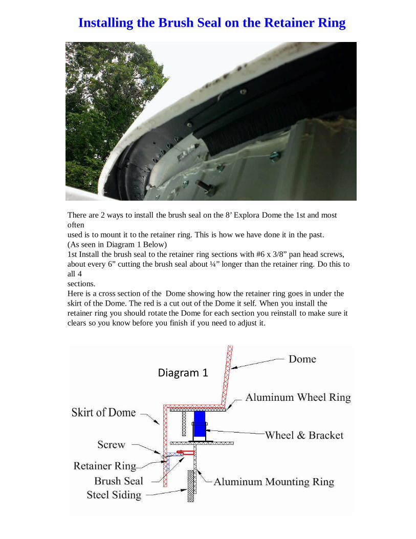
There are 2 ways to install the brush seal on the 8’ Explora Dome the 1st and mostoftenused is to mount it to the retainer ring. This is how we have done it in the past.(As seen in Diagram 1 Below)1st Install the brush seal to the retainer ring sections with #6 x 3/8” pan head screws,about every 6” cutting the brush seal about ¼” longer than the retainer ring. Do this toall 4sections.Here is a cross section of the Dome showing how the retainer ring goes in under theskirt of the Dome. The red is a cut out of the Dome it self. When you install theretainer ring you should rotate the Dome for each section you reinstall to make sure itclears so you know before you finish if you need to adjust it.
Diagram 1

Installing the Brush Seal on the Wheel Ring
The 2nd way is to Install the brush seal to the outside of the wheel ring before you put theDome ontop of the wheel ring. Starting about 1” in from the end of the brush seal and drill a 11/64”hole through the rubber brush seal and the aluminum ring and install a using #10-32X3/8hex head self threading screws, this should be done about every 6” all the way around.(As seen in Diagram 2)
Now set the Dome on to the wheel ring, most times you do not need to fasten the Dometo the wheel ring, but if you like you can fasten it down with 1 or 2 ¼” X 1” SS flange headbolt with a ¼” ss nylon lock nut on the inside.This wheel ring has the drive track all read install not all wheel ring come this way.
Diagram 2

Here is a cross section of the Deluxe Dome showing how the retainer ring goes in underthe skirt of the Dome. The red angle is the retainer ring. When you install the retainer ringyou should rotate the Dome for each section you install to make sure it clears, so youknow before you finish if you need to adjust the retainer ring sections.
Cross Section View 53 "
91 "
Front View of Door Frame
Front Band
47 "36 "
50 "
RetainerRing
97 "
60 "