exploration of aerated-liquid jets using x-ray phase...
TRANSCRIPT
ICLASS 2012, 12th Triennial International Conference on Liquid Atomization and Spray Systems, Heidelberg, Germany, September 2-6, 2012
1
Exploration of Aerated-Liquid Jets Using X-Ray Phase Contrast Imaging and X-
Ray Radiography
Kuo-Cheng Lin1*
, Campbell Carter2, Alan Kastengren
3 and Kamel Fezzaa
3
1Taitech, Inc., Beavercreek, Ohio 45430, USA
2Air Force Research Laboratory, Wright-Patterson AFB, Ohio 45433, USA
3Argonne National Laboratory, Chicago, IL 60439, USA
Abstract
The structures of aerated-liquid jets were explored using the X-ray phase contrast imaging (PCI) and X-ray ra-
diography available at the Argonne National Laboratory. Water and nitrogen were used as the injectant and aerating
gas, respectively. An axisymmetric aerated-liquid injector equipped with an exit adaptor was utilized for the inves-
tigation of external spray structures. A total of three adaptors with various internal configurations and a throat di-
ameter of 1.0 mm were selected for testing. The major motivation of this study was to obtain a better understanding
of the near-field structures of optically-dense aerated-liquid jets. In the peripheral region of aerated-liquid jets, the
measurements from the X-ray PCI technique give both a qualitative understanding of microscopic structures, such
the presence of small droplets, ligaments, and even bubbles, and also quantitative size distributions of the disinte-
grated small objects. The measurements from X-ray radiography provide quantitative liquid mass distribution pro-
files within the dense near-field region of an aerated-liquid jet. A combination of the two sets of measurements
gives a more complete picture of the near-field structures of aerated-liquid jets.
Introduction
Liquid jet atomization plays an important role in establishing stable and efficient combustion inside the com-
bustor of a liquid-fueled air-breathing propulsion system. For applications requiring both deep fuel penetration into
high-speed crossflows for broader fuel spreading and smaller droplets in the liquid spray for faster evaporation, a
superior liquid injection scheme is therefore sought. Among the possible candidates, aerated-liquid (or effervescent,
or barbotage) jets have been explored extensively. It has been shown that the liquid aeration technique can generate
a spray that penetrates well into the flow and produces a large fuel plume containing a large number of small drop-
lets [1], [2]. The required amount of aerating gas and delivery pressure are practically obtainable in a high-speed air-
breathing propulsion system. The utilization of aerated-liquid jets has led to successful combustion in a liquid-
fueled high-speed air-breathing combustor [3].
While macroscopic and far-field features of the aerated-liquid jets have been extensively examined, detailed
near-field spray structures cannot easily be explored, because of the limits of currently available instrumentation.
The relatively dense spray structure of an aerated-liquid jet prohibits the use of conventional shadowgraph imaging
and/or phase Doppler particle analyzer (PDPA). The holographic technique offers limited success in measuring
droplet size and velocity in the vicinity of the near-field jet [4]. Liquid breakup mechanisms in the near field region
of aerated-liquid jets injected into a quiescent environment have been investigated using ballistic imaging [5]. Larg-
er structures, such as intact liquid core, ligaments, and large droplets, can be imaged and identified within a dense
spray filled with fine droplets. Recently, the X-ray phase contrast imaging (PCI) and X-ray radiography techniques,
available at the Argonne National Laboratory, were utilized to characterize dense diesel sprays and aerated-liquid
jets [6]-[8].
The objective of the present study is to experimentally investigate the near-field structures of aerated-liquid jets
injected through several specially contoured nozzles into a quiescent environment, using both X-ray PCI and the X-
ray radiography. X-ray PCI observations of microscopic spray structures will be combined with X-ray radiography
measurements of liquid phase distributions within spray plumes to give a broad picture of the near-field structures
of aerated-liquid jets.
Experimental Methods
Experimental Setup
The experiment was conducted at the XOR 32-ID and the 7-BM beamlines of the Advanced Photon Source
(APS) at Argonne National Laboratory. For the present study, a water spray (into a quiescent environment) was
placed in the path of a small X-ray beam. Water and nitrogen were supplied into the aerated-liquid injector at de-
sired flow rates to form a two-phase mixture inside the injector before discharge into a quiescent environment. An
* Corresponding author: [email protected]
12th ICLASS 2012 Exploration of Aerated-Liquid Jets Using X-Ray PCI and X-Ray Radiography
2
axisymmetric aerated-liquid injector with an internal diameter of 2.0 mm in the mixing chamber was designed, as
shown in Fig. 1. An adaptor with a specific internal contour, as shown in Fig. 2, can be mounted at the injector exit
to provide the desired transition from the 2.0 mm injector exit to a throat diameter of 1.0 mm. Table 1 lists the se-
lected internal contours. These contour profiles provide additional means to modify the two-phase mixture through,
for example, pressure variation and cavitation, before the mixture discharges into a quiescent environment. Two sets
of adaptors with lengths of 2.5 mm (L/D=2.5) and 10.0 mm (L/D=10) were tested to explore the effects of passage
length and contour curvature on spray structure. The aerated-liquid jet was vertically discharged into a collecting
bucket with a small opening on the cap to prevent stray droplets from entering the beam path. In addition, the dis-
tance between the nozzle exit and the bucket cap was kept around 15 mm, in order to avoid splashing. Both the ae-
rated-liquid injector and the collecting bucket were rigidly mounted on a traversing table, which provided move-
ment normal to the X-ray beam.
Table 1 Dimensions of the exit adaptor for the axisymmetric aerated-liquid injector
Configurationa #1 #2 #3
D1 2.0 mm 2.0 mm 2.0 mm
D2 (throat) 1.0 mm 1.0 mm 1.0 mm aL=2.5 mm (L/D=2.5 with D=1.0 mm) and L=10 mm (L/D=10 with D=1.0 mm)
Figure 1 Photograph of axisymmetric aerated-liquid injector with exchangeable nozzle adaptors.
#1 #2 #3
Figure 2 Adaptor internal contours for the axisymmetric aerated-liquid injector with 2.0 mm in the mixing cham-
ber. Detailed dimensions in Table 1.
(a) (b)
Figure 3 Zoom-in contrast-enhanced X-ray PCI images illustrating typical appearance of a) droplet and b) gas
void (bubble).
X-Ray Phase Contrast Imaging
The X-ray PCI setup is available at the XOR 32-ID beamline. The undulator source provides the high X-ray
brilliance necessary for the white-beam ultra-fast imaging technique. With an optimized undulator gap, most of the
intensity was located within the first harmonic at 13.3 keV, with a peak irradiance of 1014
ph/s/mm2/0.1%bw and a
natural bandwidth of 0.3 keV FWHM. A fast scintillator crystal (LYSO:Ce with a 40 ns decay time) converted the
transmitted X-rays into visible light (434 nm). The images, with a field of view of 1.5 1.9 mm2, were captured
with a CCD camera (Sensicam HS-SVGA, 10241280 pixels, from Cooke Corp.) coupled to the scintillator via a
microscope objective (x5, NA=0.14) and a 45º mirror. Proper synchronization of a fast mechanical shuttering sys-
tem and the CCD camera permitted isolation and capture of X-ray pulses emanating from single bunches from the
storage ring. Thus, even though the CCD camera shutter stayed open for about 1µs, the actual exposure time was
only as long as the pulse itself, that is 150 ps (FWHM).
The obtained X-ray image is the projection of three-dimensional information within the spray onto a two-
dimensional detector plane. Therefore, the line-of-sight nature of the X-ray images may inhibit detailed interroga-
ICLASS 2012, 12th Triennial International Conference on Liquid Atomization and Spray Systems, Heidelberg, Germany, September 2-6, 2012
3
tion of the dense spray core, as will be discussed later. Each X-ray image was digitally processed with an in-house
code to remove the undesirable background noise with an enhanced contrast ratio.
X-ray PCI images of microscopic structures, including a liquid droplet and gas void (or bubble), are presented
in Fig. 3. For the liquid droplet outside a liquid column identified inside the zoom-in box in Fig. 3(a), a bright halo
appears at the outmost boundary, followed by a dark halo inside. For the gas void inside a liquid column identified
inside the zoom-in box in Fig. 3(b), a dark halo appears at the outermost boundary, with a bright halo inside. With
these unique features, droplets and bubbles were identified with the in-house code for size measurement. With a
relatively low droplet number density within the probing region, a significant number of objects are well separated
from each other. These objects then pass an imposed roundness test to be defined as valid droplets or bubbles for
size measurement. Large objects are more likely to overlap with nearby objects in the projected two-dimensional X-
ray image and therefore, may be rejected for size measurement. Objects with an effective diameter of approximately
4.5 m or less consist of a small number of rectangular image pixels and are, therefore, more likely to fail the im-
posed roundness test.
A set of 10 images was obtained for each probing location. Typically, Sauter mean diameters (SMD) of suc-
cessfully-measured droplets and bubbles are calculated and presented for the subsequent discussion. For the region
close to the spray core, however, the highly overlapping features make object identification nearly impossible and,
thus, no size measurement can be made within this region. Figure 4 illustrates the typical workable region for size
measurement for an aerated-liquid jet injected into a quiescent environment.
Figure 4 Droplet size distribution contours superimposed with the composite X-ray image to illustrate the typical
workable region for size measurement for an aerated-liquid jet injected into a quiescent environment. mL=18.2 g/s,
GLR=4%, Configuration #3 adaptor, L/D=10. The physical dimension of the liquid jet in the vertical direction is 7.2
mm. The left-hand side of the composite image is a mirrored image.
X-Ray Radiography
The X-ray radiography facility available at the 7-BM beamline at Argonne National Laboratory is described in
detail in the study of Kastengren et al. [8] For the current experiments, the X-ray beam photon energy was 6 keV.
This provides a good compromise between absorption of the beam by the spray and excessive absorption by X-ray
windows and ambient air. The beam was focused using a pair of 300 mm long Kirkpatrick-Baez focusing mirrors.
The beam focus is approximately 5 6 µm FWHM V H, located approximately 400 mm from of the center of the
horizontal focusing mirror. The effective size of the beam for the current sprays (which are several milimeters wide)
is somewhat greater than this minimum focus size.
The radiography measurements provide a quantitative measurement of the spray density integrated along the
beam path. In order to build a two-dimensional representation of the spray, a raster scan approach is used, with indi-
vidual measurements performed at multiple locations. The X-ray detector for these experiments is an unbiased sili-
con 300 µm thick PIN diode. This detector absorbs virtually all of the X-rays incident on the detector, converting
the X-rays into a weak photocurrent. This current is amplified with a high-speed transimpedance amplifier, with the
resulting voltage integrated for 1.0 s at each measurement location.
According to Beer’s law, the relationship between the absorption of light and the properties of the material
through which the light is travelling can be described as follows:
xeI
I 0
(1)
where I and I0 are the intensity of the transmitted light and the incident light, respectively, measured by the PIN
diode, is the linear attenuation coefficient, and x is the path length of the X-ray beam through the medium of in-
terest. For the present study, the medium of interest is a multiphase flow consisting of air and a dispersed multi-
phase mixture of fine droplets and ligaments.
12th ICLASS 2012 Exploration of Aerated-Liquid Jets Using X-Ray PCI and X-Ray Radiography
4
Equation (1) can be further manipulated as follows:
)ln(ln 00 IIIIx
(2)
where is the mass attenuation coefficient and is equal to (/). For pure water at room temperature with a density
of 1.0 g/cm3 and mass attenuation coefficient of 24.64 cm
2/g at 6.0 keV with coherent scattering, the path length
derived from Eq. (2) is the equivalent path length (EPL). The mass attenuation coefficient was calculated using the
NIST photon cross sections database [9]. The EPL is the thickness of pure water required for the transmitting X-ray
to generate the same amount of extinction as that generated from the dispersed spray at the same X-ray energy level.
The value of the EPL can, therefore, be related to the local density of the liquid/air mixture or local liquid mass frac-
tion. For the present study, only the two-dimensional line-of-sight EPL will be presented to depict the spray struc-
ture. No attempt was made to resolve the three-dimensional distribution of EPL through mathematical schemes such
as Abel inversion.
Shown in Fig. 5 are the spray appearance, recorded using the X-ray PCI technique, and the distribution profiles
of the measured line-of-sight equivalent path length of a pure-liquid jet. The Configuration #1 adapter with an L/D
of 10 was utilized to inject water at a flow rate of 18.2 g/s. X-ray scanning was carried out at three axial locations
close to the exit orifice from x=0.5 to x=1.5 mm. As can be seen in Fig. 5(b), the centerline values of the line-of-
sight equivalent path length at these three axial locations are fairly close to 1.0 mm. The extrapolated value of the
centerline equivalent path length at the adapter exit plane (x=0) is 0.983 mm, as illustrated in Fig. 5(c). This value
matches exceptionally well with the exit orifice diameter of the adapter, taking into account the uncertainties in
hardware machining, experiment execution, and data reduction.
(a) (b) (c)
Figure 5 Spray appearance and measured line-of-sight equivalent path lengths for pure-liquid jet. (a) Spray ap-
pearance from X-ray PCI and locations measured by X-ray radiography, (b) radial distribution profiles of the equiv-
alent path length, (c) centerline values of equivalent path lengths from x=0.5 mm to x=1.5 mm. Configuration #1,
L/D=10, mL =18.2 g/s, GLR=0.
Results and Discussion
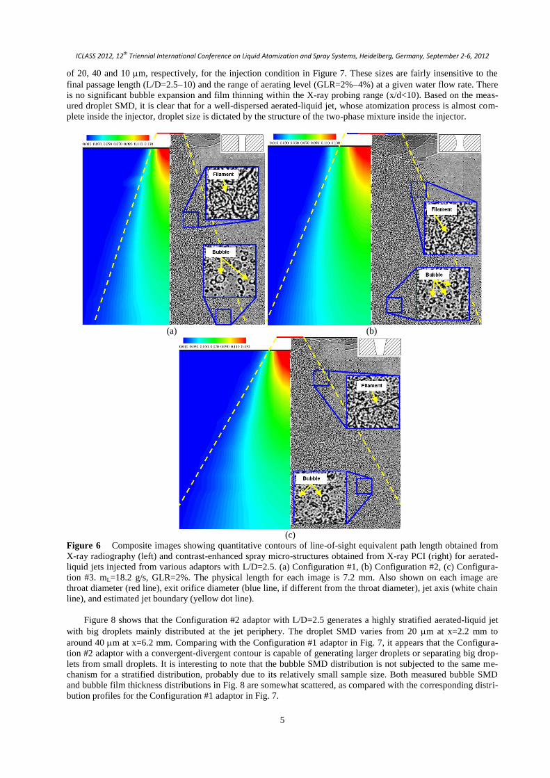
Figure 6 shows composite spray images of contrast-enhanced spray micro-structures obtained from X-ray PCI
and the quantitative contours of the line-of-sight equivalent path length obtained from X-ray radiography. The ae-
rated-liquid jets shown here were injected from the Configurations #1 #3 adaptors with L/D=2.5. Liquid flow rate
and aeration level were kept at 18.2 g/s and 2%, respectively.
The X-ray PCI technique offers both a qualitative understanding of microscopic structures on the periphery of
the jet, including small droplets, ligaments, and even bubbles, as highlighted in the zoom-in boxes in each figure,
and also quantitative size distributions of the disintegrated small objects in the same region. That technique, howev-
er, cannot depict either the structure within the core region of the spray or the liquid mass distribution within the
plume. To supplement these deficiencies, the measurements from the X-ray radiography give quantitative distribu-
tions of liquid mass within the dense spray region. Cross-sectional liquid distribution patterns within the aerated-
liquid jets, such as annular or uniform distribution, can be observed from the line-of-sight measurements, as will be
discussed later. The structure of the two-phase mixtures inside the injector at various injection conditions can also
be inferred from the X-ray radiography measurements in the near field. In general, the combination of both X-ray
diagnostic techniques gives a complete understanding of aerated-liquid jets in the near field.
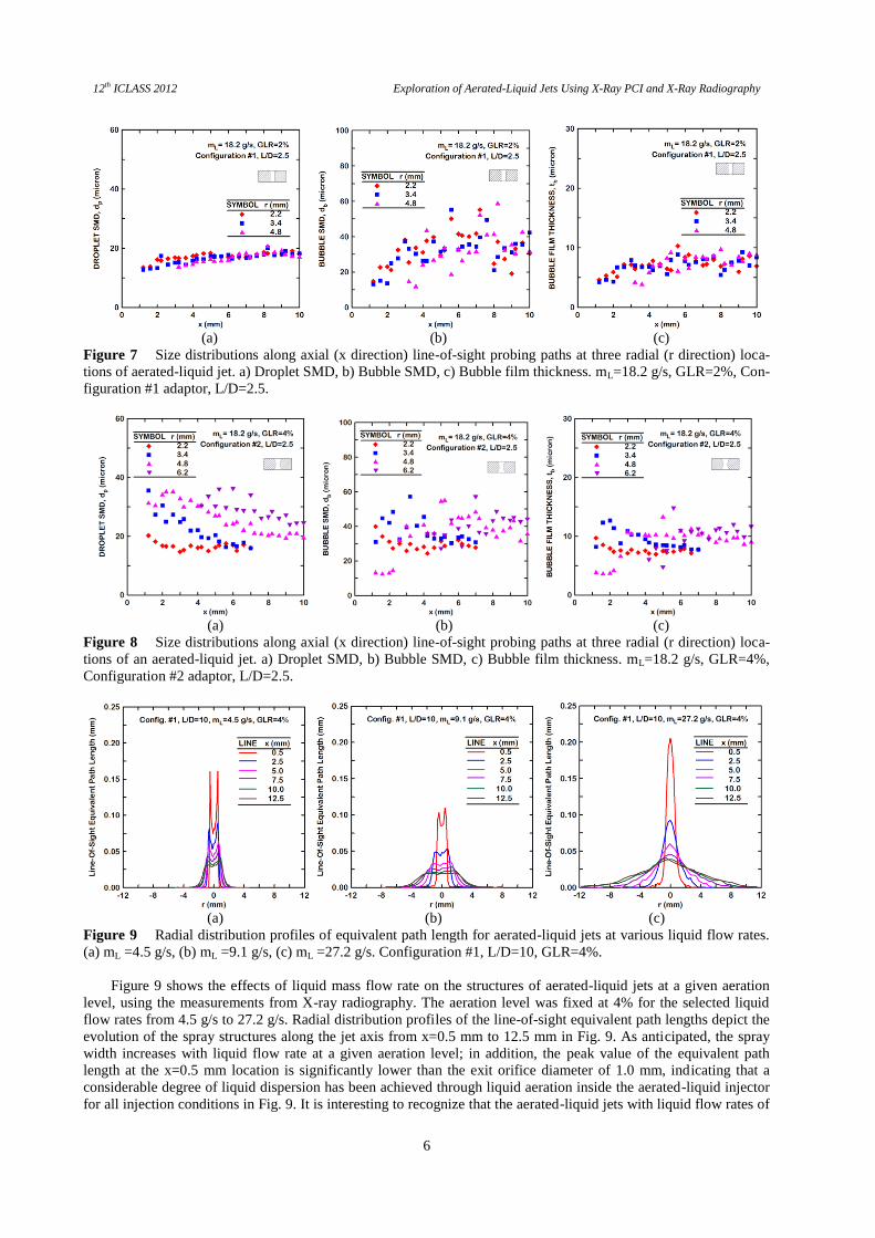
Figures 7 and 8 illustrate size distributions along the axial (x direction) line-of-sight probing paths at three radi-
al (r direction) locations in two aerated-liquid jets, using the images obtained from X-ray PCI. Due to the constraints
of line-of-sight projection, only the injection conditions, which can create a highly dispersed aerated-liquid jet, were
selected for size measurement. The measured droplet SMD, bubble SMD and bubble film thickness are on the order
ICLASS 2012, 12th Triennial International Conference on Liquid Atomization and Spray Systems, Heidelberg, Germany, September 2-6, 2012
5
of 20, 40 and 10 m, respectively, for the injection condition in Figure 7. These sizes are fairly insensitive to the
final passage length (L/D=2.510) and the range of aerating level (GLR=2%4%) at a given water flow rate. There
is no significant bubble expansion and film thinning within the X-ray probing range (x/d<10). Based on the meas-
ured droplet SMD, it is clear that for a well-dispersed aerated-liquid jet, whose atomization process is almost com-
plete inside the injector, droplet size is dictated by the structure of the two-phase mixture inside the injector.
(a) (b)
(c)
Figure 6 Composite images showing quantitative contours of line-of-sight equivalent path length obtained from
X-ray radiography (left) and contrast-enhanced spray micro-structures obtained from X-ray PCI (right) for aerated-
liquid jets injected from various adaptors with L/D=2.5. (a) Configuration #1, (b) Configuration #2, (c) Configura-
tion #3. mL=18.2 g/s, GLR=2%. The physical length for each image is 7.2 mm. Also shown on each image are
throat diameter (red line), exit orifice diameter (blue line, if different from the throat diameter), jet axis (white chain
line), and estimated jet boundary (yellow dot line).
Figure 8 shows that the Configuration #2 adaptor with L/D=2.5 generates a highly stratified aerated-liquid jet
with big droplets mainly distributed at the jet periphery. The droplet SMD varies from 20 m at x=2.2 mm to
around 40 m at x=6.2 mm. Comparing with the Configuration #1 adaptor in Fig. 7, it appears that the Configura-
tion #2 adaptor with a convergent-divergent contour is capable of generating larger droplets or separating big drop-
lets from small droplets. It is interesting to note that the bubble SMD distribution is not subjected to the same me-
chanism for a stratified distribution, probably due to its relatively small sample size. Both measured bubble SMD
and bubble film thickness distributions in Fig. 8 are somewhat scattered, as compared with the corresponding distri-
bution profiles for the Configuration #1 adaptor in Fig. 7.
12th ICLASS 2012 Exploration of Aerated-Liquid Jets Using X-Ray PCI and X-Ray Radiography
6
(a) (b) (c)
Figure 7 Size distributions along axial (x direction) line-of-sight probing paths at three radial (r direction) loca-
tions of aerated-liquid jet. a) Droplet SMD, b) Bubble SMD, c) Bubble film thickness. mL=18.2 g/s, GLR=2%, Con-
figuration #1 adaptor, L/D=2.5.
(a) (b) (c)
Figure 8 Size distributions along axial (x direction) line-of-sight probing paths at three radial (r direction) loca-
tions of an aerated-liquid jet. a) Droplet SMD, b) Bubble SMD, c) Bubble film thickness. mL=18.2 g/s, GLR=4%,
Configuration #2 adaptor, L/D=2.5.
(a) (b) (c)
Figure 9 Radial distribution profiles of equivalent path length for aerated-liquid jets at various liquid flow rates.
(a) mL =4.5 g/s, (b) mL =9.1 g/s, (c) mL =27.2 g/s. Configuration #1, L/D=10, GLR=4%.
Figure 9 shows the effects of liquid mass flow rate on the structures of aerated-liquid jets at a given aeration
level, using the measurements from X-ray radiography. The aeration level was fixed at 4% for the selected liquid
flow rates from 4.5 g/s to 27.2 g/s. Radial distribution profiles of the line-of-sight equivalent path lengths depict the
evolution of the spray structures along the jet axis from x=0.5 mm to 12.5 mm in Fig. 9. As anticipated, the spray
width increases with liquid flow rate at a given aeration level; in addition, the peak value of the equivalent path
length at the x=0.5 mm location is significantly lower than the exit orifice diameter of 1.0 mm, indicating that a
considerable degree of liquid dispersion has been achieved through liquid aeration inside the aerated-liquid injector
for all injection conditions in Fig. 9. It is interesting to recognize that the aerated-liquid jets with liquid flow rates of
ICLASS 2012, 12th Triennial International Conference on Liquid Atomization and Spray Systems, Heidelberg, Germany, September 2-6, 2012
7
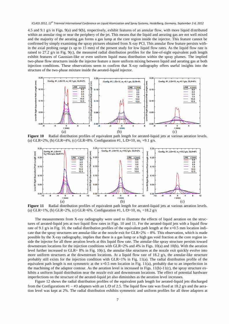
4.5 and 9.1 g/s in Figs. 9(a) and 9(b), respectively, exhibit features of an annular flow, with more liquid distributed
within an annular ring or near the periphery of the jet. This means that the liquid and aerating gas are not well mixed
and the majority of the aerating gas forms a gas lump at the core region inside the injector. This feature cannot be
confirmed by simply examining the spray pictures obtained from X-ray PCI. This annular flow feature persists with-
in the axial probing range (x up to 15 mm) of the present study for low liquid flow rates. As the liquid flow rate is
raised to 27.2 g/s in Fig. 9(c), the measured radial distribution profiles for the line-of-sight equivalent path length
exhibit features of Gaussian-like or even uniform liquid mass distribution within the spray plumes. The implied
two-phase flow structures inside the injector feature a more uniform mixing between liquid and aerating gas at both
injection conditions. These observations seem to confirm that X-ray radiography offers useful insights into the
structure of the two-phase mixture inside the aerated-liquid injector.
(a) (b) (c)
Figure 10 Radial distribution profiles of equivalent path length for aerated-liquid jets at various aeration levels.
(a) GLR=2%, (b) GLR=4%, (c) GLR=8%. Configuration #1, L/D=10, mL =9.1 g/s.
(a) (b) (c)
Figure 11 Radial distribution profiles of equivalent path length for aerated-liquid jets at various aeration levels.
(a) GLR=1%, (b) GLR=2%, (c) GLR=6%. Configuration #1, L/D=10, mL =18.2 g/s
The measurements from X-ray radiography were used to illustrate the effects of liquid aeration on the struc-
tures of aerated-liquid jets at two liquid flow rates in Figs. 10 and 11. For the aerated-liquid jets with a liquid flow
rate of 9.1 g/s in Fig. 10, the radial distribution profiles of the equivalent path length at the x=0.5 mm location indi-
cate that the spray structures are annular-like at the nozzle exit for GLR=2% 8%. This observation, which is made
possible by the X-ray radiography, implies that there is a gas lump or a high gas void fraction at the core region in-
side the injector for all three aeration levels at this liquid flow rate. The annular-like spray structure persists toward
downstream locations for the injection conditions with GLR=2% and 4% in Figs. 10(a) and 10(b). With the aeration
level further increased to GLR= 8% in Fig. 10(c), the annular-like structures at the nozzle exit quickly evolve into
more uniform structures at the downstream locations. At a liquid flow rate of 18.2 g/s, the annular-like structure
probably still exists for the injection condition with GLR=1% in Fig. 11(a). The radial distribution profile of the
equivalent path length is not symmetric at the x=0.5 mm location in Fig. 11(a), probably due to an imperfection in
the machining of the adaptor contour. As the aeration level is increased in Figs. 11(b)-11(c), the spray structure ex-
hibits a uniform liquid distribution near the nozzle exit and downstream locations. The effect of potential hardware
imperfections on the structure of the aerated-liquid jet also diminishes as the aeration level increases.
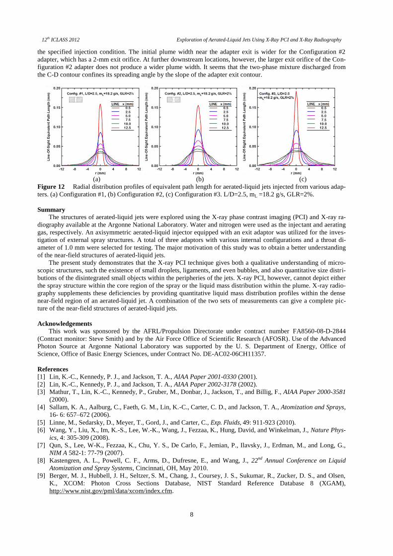
Figure 12 shows the radial distribution profiles of the equivalent path length for aerated-liquid jets discharged
from the Configurations #1 #3 adapters with an L/D of 2.5. The liquid flow rate was fixed at 18.2 g/s and the aera-
tion level was kept at 2%. The radial distribution exhibits symmetric and uniform profiles for all three adapters at
12th ICLASS 2012 Exploration of Aerated-Liquid Jets Using X-Ray PCI and X-Ray Radiography
8
the specified injection condition. The initial plume width near the adapter exit is wider for the Configuration #2
adapter, which has a 2-mm exit orifice. At further downstream locations, however, the larger exit orifice of the Con-
figuration #2 adapter does not produce a wider plume width. It seems that the two-phase mixture discharged from
the C-D contour confines its spreading angle by the slope of the adapter exit contour.
(a) (b) (c)
Figure 12 Radial distribution profiles of equivalent path length for aerated-liquid jets injected from various adap-
ters. (a) Configuration #1, (b) Configuration #2, (c) Configuration #3. L/D=2.5, mL =18.2 g/s, GLR=2%.
Summary
The structures of aerated-liquid jets were explored using the X-ray phase contrast imaging (PCI) and X-ray ra-
diography available at the Argonne National Laboratory. Water and nitrogen were used as the injectant and aerating
gas, respectively. An axisymmetric aerated-liquid injector equipped with an exit adaptor was utilized for the inves-
tigation of external spray structures. A total of three adaptors with various internal configurations and a throat di-
ameter of 1.0 mm were selected for testing. The major motivation of this study was to obtain a better understanding
of the near-field structures of aerated-liquid jets.
The present study demonstrates that the X-ray PCI technique gives both a qualitative understanding of micro-
scopic structures, such the existence of small droplets, ligaments, and even bubbles, and also quantitative size distri-
butions of the disintegrated small objects within the peripheries of the jets. X-ray PCI, however, cannot depict either
the spray structure within the core region of the spray or the liquid mass distribution within the plume. X-ray radio-
graphy supplements these deficiencies by providing quantitative liquid mass distribution profiles within the dense
near-field region of an aerated-liquid jet. A combination of the two sets of measurements can give a complete pic-
ture of the near-field structures of aerated-liquid jets.
Acknowledgements
This work was sponsored by the AFRL/Propulsion Directorate under contract number FA8560-08-D-2844
(Contract monitor: Steve Smith) and by the Air Force Office of Scientific Research (AFOSR). Use of the Advanced
Photon Source at Argonne National Laboratory was supported by the U. S. Department of Energy, Office of
Science, Office of Basic Energy Sciences, under Contract No. DE-AC02-06CH11357.
References
[1] Lin, K.-C., Kennedy, P. J., and Jackson, T. A., AIAA Paper 2001-0330 (2001).
[2] Lin, K.-C., Kennedy, P. J., and Jackson, T. A., AIAA Paper 2002-3178 (2002).
[3] Mathur, T., Lin, K.-C., Kennedy, P., Gruber, M., Donbar, J., Jackson, T., and Billig, F., AIAA Paper 2000-3581
(2000).
[4] Sallam, K. A., Aalburg, C., Faeth, G. M., Lin, K.-C., Carter, C. D., and Jackson, T. A., Atomization and Sprays,
16- 6: 657–672 (2006).
[5] Linne, M., Sedarsky, D., Meyer, T., Gord, J., and Carter, C., Exp. Fluids, 49: 911-923 (2010).
[6] Wang, Y., Liu, X., Im, K.-S., Lee, W.-K., Wang, J., Fezzaa, K., Hung, David, and Winkelman, J., Nature Phys-
ics, 4: 305-309 (2008).
[7] Qun, S., Lee, W-K., Fezzaa, K., Chu, Y. S., De Carlo, F., Jemian, P., Ilavsky, J., Erdman, M., and Long, G.,
NIM A 582-1: 77-79 (2007).
[8] Kastengren, A. L., Powell, C. F., Arms, D., Dufresne, E., and Wang, J., 22nd
Annual Conference on Liquid
Atomization and Spray Systems, Cincinnati, OH, May 2010.
[9] Berger, M. J., Hubbell, J. H., Seltzer, S. M., Chang, J., Coursey, J. S., Sukumar, R., Zucker, D. S., and Olsen,
K., XCOM: Photon Cross Sections Database, NIST Standard Reference Database 8 (XGAM),
http://www.nist.gov/pml/data/xcom/index.cfm.