explorer guitar kit assembly instructions guitar kit assembly instructions . introduction explorer...
TRANSCRIPT
Introduction
Explorer Intro- 1 -
Warning
These instructions assume that you are familiar with the safe operation and use of woodworking machinery
and woodworking tools, and understand the techniques used to assemble this project. If you do not qualify
for both of these criteria, STOP building this project for your own safety. Read and understand the owner’s
manual for the machinery you intend to use, take a woodworking class or visit your local library for more
information. Woodworking machinery and tools are inherently dangerous because they use sharp edges
that can and will cause serious personal injury including amputation and death. Do not underestimate the
ability of these tools and machinery to cause injury. Never operate any tool without all guards in place and
always wear approved safety glasses. For your own safety, please heed this warning.
Warning
Always wear safety glasses or goggles when operating equipment. Everyday glasses or reading glasses are
not safety glasses. Be certain the safety glasses you wear meet the appropriate standards of the American
National Standards Institute (ANSI). Because there are various ways to cut and join wood, you can make
substitutions for the methods stated in this manual. We try to suggest the easiest methods possible.
However, only you know your skills with each piece of machinery. Never compromise your safety by using
a cutting method with which you are not comfortable. Instead, find an alternative approach that will yield
the same result.
WARNING
Some dust created by power sanding, sawing, grinding, drilling, and other construction activities contains
chemicals known to the State of California to cause cancer, birth defects or other reproductive harm.
Some examples of these chemicals are:
Lead from lead-based paints.
Crystalline silica from bricks, cement, and other masonry products.
Arsenic and chromium from chemically treated lumber.
Your risk from these exposures varies, depending on how often you do this type of work. To reduce your
exposure to these chemicals: work in a well ventilated area, and work with approved safety equipment,
such as those dust masks that are specially designed to filter out microscopic particles.

Introduction
Explorer Intro- 2 -
Contents Contents .................................................................................................................................................... - 2 -
1 Introduction ...................................................................................................................................... - 4 -
1.2 Material Check List .................................................................................................................... - 5 -
1.3 Additional tools/materials required: ........................................................................................ - 8 -
2 Mockup and Fit Check (Figure 2.0) ................................................................................................... - 1 -
2.1 Fit check the Neck to the Body ................................................................................................. - 1 -
2.2 Checking the Pickups, Pickguard and Truss access cover ......................................................... - 1 -
2.2.1 Mounting of Pickups & Pickguard (reference Figure 2.0) ................................................. - 1 -
2.2.2 Truss access cover (Figure 2.2.2-1) ................................................................................... - 2 -
2.3 Checking Electrical wiring and components ............................................................................. - 2 -
2.4 Check Bridge assembly (Figure 2.4-1) ....................................................................................... - 2 -
2.5 Miscellaneous Fit Checks .......................................................................................................... - 3 -
2.5.1 Fit check of the back cavity Cover (Fig 2.5.1-1)................................................................. - 3 -
2.5.2 Output Jack ....................................................................................................................... - 3 -
2.5.3 Check Strap Pins ................................................................................................................ - 3 -
2.5.4 Check Tuner Alignment ..................................................................................................... - 3 -
3 Finish ................................................................................................................................................. - 1 -
3.1 Finish Application Steps ............................................................................................................ - 2 -
3.1.1 Solid Color finish: .............................................................................................................. - 2 -
3.1.2 Pigmented Translucent, Gel stain or alcohol dye finish:................................................... - 2 -
3.1.3 Penetrating Stain or water based dye finish: .................................................................... - 2 -
3.2 Explanation of Sequence Steps: ................................................................................................ - 2 -
3.2.1 Sanding the Body and Neck .............................................................................................. - 2 -
3.2.2 Appling Grain Filler ............................................................................................................ - 3 -
3.2.3 Applying Sanding Sealer .................................................................................................... - 3 -
3.2.4 Solid Color Primer ............................................................................................................. - 3 -
3.2.5 Burst and Translucent finishes .......................................................................................... - 4 -
3.2.6 Clear Top coats .................................................................................................................. - 4 -
3.2.7 Buff finish .......................................................................................................................... - 4 -
4 Assembly ........................................................................................................................................... - 1 -

Introduction
Explorer Intro- 3 -
4.1 Installing the Neck ..................................................................................................................... - 2 -
4.1.1 Neck Positioning: Neck Cavity Insertion ........................................................................... - 2 -
4.1.2 Neck Positioning: Centering .............................................................................................. - 2 -
4.1.3 Neck positioning: neck angle ............................................................................................ - 3 -
4.1.4 Neck Installation: gluing in place ...................................................................................... - 3 -
4.2 Installation of the Electronic Components ............................................................................... - 4 -
4.2.1 Installing the Wiring Harness ............................................................................................ - 4 -
4.2.2 Install Neck Pickup ............................................................................................................ - 5 -
4.2.3 Install the Bridge pickup (Reference Figure 4.2) ............................................................... - 5 -
4.2.4 Selector Switch Wiring (Reference Figure 4.2) ................................................................. - 6 -
4.2.5 Install the Pickguard and Selector Switch ......................................................................... - 6 -
4.3 Installation of the Bridge Components ..................................................................................... - 7 -
4.3.1 Installing the Bridge .......................................................................................................... - 7 -
4.3.2 Installing the Tailpiece ...................................................................................................... - 7 -
4.4 Installing the Nut ....................................................................................................................... - 7 -
4.5 Installing the Tuners & Truss Rod Cover (Figure 4.5-1) ............................................................ - 8 -
4.5.1 Installing the Tuners .......................................................................................................... - 8 -
4.5.2 Installing the Truss Rod Cover ........................................................................................... - 8 -
4.6 Install the Strings....................................................................................................................... - 8 -
4.7 Installing the Strap Pins ............................................................................................................. - 8 -
5 Initial setup ....................................................................................................................................... - 1 -
5.1 Adjust the Guitar Neck: Truss Rod ............................................................................................ - 2 -
5.1.1 Check the Neck .................................................................................................................. - 2 -
5.1.2 Adjusting the Truss Rod .................................................................................................... - 2 -
5.2 String Lubrication ...................................................................................................................... - 2 -
5.3 Adjusting the Action .................................................................................................................. - 3 -
5.3.1 The Nut .............................................................................................................................. - 3 -
5.3.2 Bridge Saddle Adjustment................................................................................................. - 3 -
5.4 Pickup Height (Figure 5.4) ......................................................................................................... - 4 -
5.5 Intonation (Figure 5.5) .............................................................................................................. - 4 -
5.6 …Other Hints ............................................................................................................................. - 5 -
Introduction
Explorer Intro- 4 -
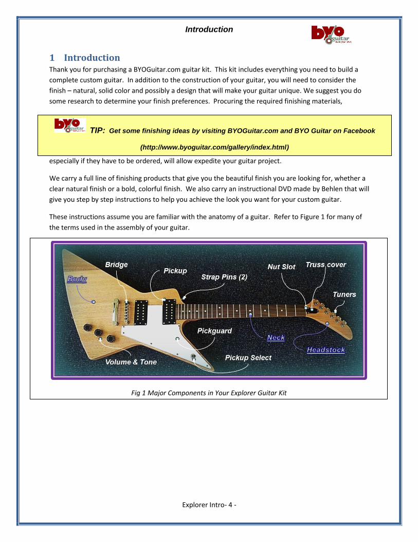
Fig 1 Major Components in Your Explorer Guitar Kit
1 Introduction Thank you for purchasing a BYOGuitar.com guitar kit. This kit includes everything you need to build a
complete custom guitar. In addition to the construction of your guitar, you will need to consider the
finish – natural, solid color and possibly a design that will make your guitar unique. We suggest you do
some research to determine your finish preferences. Procuring the required finishing materials,
especially if they have to be ordered, will allow expedite your guitar project.
We carry a full line of finishing products that give you the beautiful finish you are looking for, whether a
clear natural finish or a bold, colorful finish. We also carry an instructional DVD made by Behlen that will
give you step by step instructions to help you achieve the look you want for your custom guitar.
These instructions assume you are familiar with the anatomy of a guitar. Refer to Figure 1 for many of
the terms used in the assembly of your guitar.
TIP: Get some finishing ideas by visiting BYOGuitar.com and BYO Guitar on Facebook
(http://www.byoguitar.com/gallery/index.html)
Introduction
Explorer Intro- 5 -
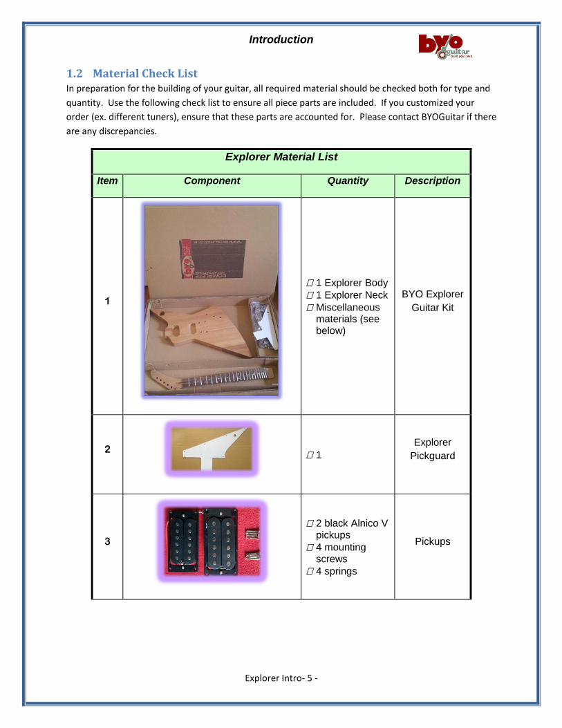
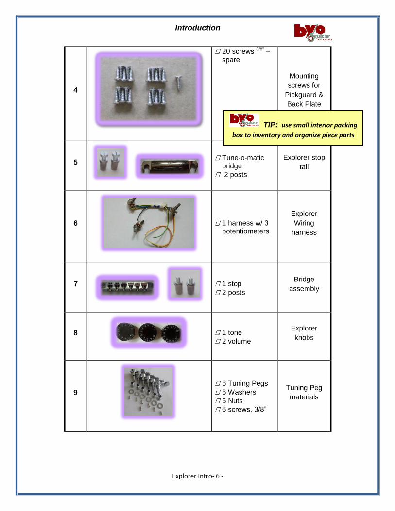
1.2 Material Check List In preparation for the building of your guitar, all required material should be checked both for type and
quantity. Use the following check list to ensure all piece parts are included. If you customized your
order (ex. different tuners), ensure that these parts are accounted for. Please contact BYOGuitar if there
are any discrepancies.
Explorer Material List
Item Component Quantity Description
1
1 Explorer Body
1 Explorer Neck
Miscellaneous materials (see below)
BYO Explorer
Guitar Kit
2
1
Explorer
Pickguard
3
2 black Alnico V pickups
4 mounting screws
4 springs
Pickups
Introduction
Explorer Intro- 6 -
4
20 screws 3/8” + spare
Mounting
screws for
Pickguard &
Back Plate
5
Tune-o-matic bridge
2 posts
Explorer stop
tail
6
1 harness w/ 3 potentiometers
Explorer
Wiring
harness
7
1 stop
2 posts
Bridge
assembly
8
1 tone
2 volume
Explorer
knobs
9
6 Tuning Pegs
6 Washers
6 Nuts
6 screws, 3/8”
Tuning Peg
materials
TIP: use small interior packing
box to inventory and organize piece parts
Introduction
Explorer Intro- 7 -
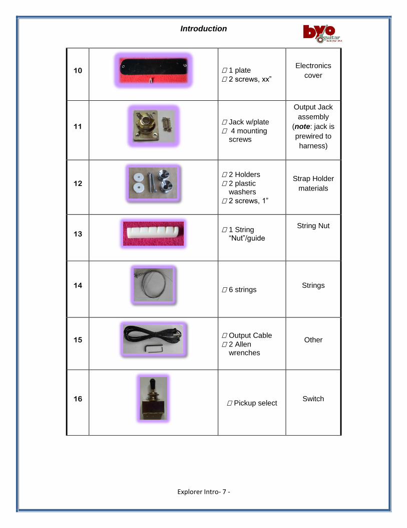
10
1 plate
2 screws, xx”
Electronics
cover
11
Jack w/plate
4 mounting screws
Output Jack
assembly
(note: jack is
prewired to
harness)
12
2 Holders
2 plastic washers
2 screws, 1”
Strap Holder
materials
13
1 String “Nut”/guide
String Nut
14
6 strings Strings
15
Output Cable
2 Allen wrenches
Other
16
Pickup select Switch
Introduction
Explorer Intro- 8 -
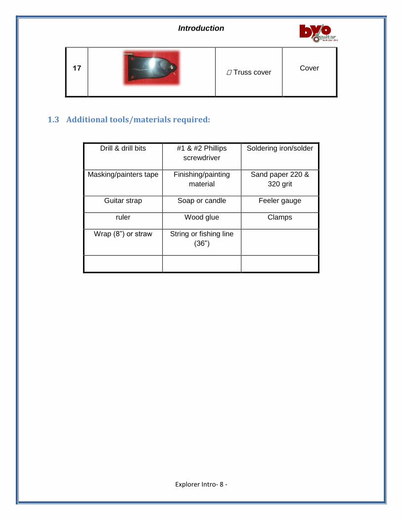
17
Truss cover Cover
1.3 Additional tools/materials required:
Drill & drill bits #1 & #2 Phillips
screwdriver
Soldering iron/solder
Masking/painters tape Finishing/painting
material
Sand paper 220 &
320 grit
Guitar strap Soap or candle Feeler gauge
ruler Wood glue Clamps
Wrap (8”) or straw String or fishing line
(36”)
Introduction
Explorer Intro- 9 -
The remainder of the assembly instruction is divided into four sections:
Section 2 – Mockup & Fit check: in this section, all components will be checked for proper
alignment and ensure that all holes have been drilled.
Section 3 – Finishing the Body and Neck: after fit check, the components are removed from the
neck & body to allow the selected finish to be applied. This will allow you to customize your guitars’
color(s). As the finishing will likely require several coats with sanding between each coat, ensure that
the finish is completely dry.
Section 4 – Assembly: the final assembly is the next step - once the finish has been applied and
completely dried. In this section, all of the components are installed, internal wiring connected and
strings attached – your guitar will ready to go!
Section 5 – Setup: in this section, initial adjustments are made to your guitar, such as the height
of the pickups.
Again, we thank you for your purchase of a BYO Guitar and we look forward to seeing pictures of your
unique guitar! We also look forward to providing you with the guitar for your next project from our
Custom Shop where you can select the wood for the body and neck as well as customizing all of the
other components.
Let us know if your music, school, church or scouting organization would like to undertake a group
project – BYO Guitar can supply multiple kits or custom guitars.
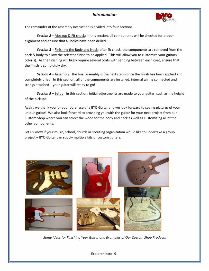
Some Ideas for Finishing Your Guitar and Examples of Our Custom Shop Products
Section 2 – Mockup and Fit Check
Explorer Section 2(Rev A) - 1 -
Section 2 Contents
2 Mockup and Fit Check (Figure 2.0) ................................................................................................... - 1 -
2.1 Fit check the Neck to the Body ..................................................................................................... - 1 -
2.2 Checking the Pickups, Pickguard and Truss access cover ............................................................. - 1 -
2.2.1 Mounting of Pickups & Pickguard (reference Figure 2.0) ................................................. - 1 -
2.2.2 Truss access cover (Figure 2.2.2-1) ................................................................................... - 2 -
2.3 Checking Electrical wiring and components ................................................................................. - 2 -
2.4 Check Bridge assembly (Figure 2.4-1) ........................................................................................... - 2 -
2.5 Miscellaneous Fit Checks .............................................................................................................. - 3 -
2.5.1 Fit check of the back cavity Cover (Fig 2.5.1-1)................................................................. - 3 -
2.5.2 Output Jack ....................................................................................................................... - 3 -
2.5.3 Check Strap Pins ................................................................................................................ - 3 -
2.5.4 Check Tuner Alignment ..................................................................................................... - 3 -
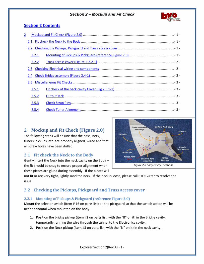
2 Mockup and Fit Check (Figure 2.0) The following steps will ensure that the base, neck,
tuners, pickups, etc. are properly aligned, wired and that
all screw holes have been drilled.
2.1 Fit check the Neck to the Body Gently insert the Neck into the neck cavity on the Body –
the fit should be snug to ensure proper alignment when
these pieces are glued during assembly. If the pieces will
not fit or are very tight, lightly sand the neck. If the neck is loose, please call BYO Guitar to resolve the
issue.
2.2 Checking the Pickups, Pickguard and Truss access cover
2.2.1 Mounting of Pickups & Pickguard (reference Figure 2.0)
Mount the selector switch (Item # 16 on parts list) on the pickguard so that the switch action will be
near horizontal when mounted on the body.
1. Position the bridge pickup (item #2 on parts list, with the “B” on it) in the Bridge cavity,
temporarily running the wire through the tunnel to the Electronics cavity.
2. Position the Neck pickup (item #3 on parts list, with the “N” on it) in the neck cavity.
Figure 2.0 Body Cavity Locations

Section 2 – Mockup and Fit Check
Explorer Section 2(Rev A) - 2 -
3. Mount the pickguard so that the matches the contour of the body while aligning the pickups to
be symmetrical with the pickguard. Realign as necessary – then mark the holes.
4. Pre-drill :
a. 2 holes for the pickguard;
b. 2 holes for each pick up;
5. Attach with supplied screws and recheck body & component alignment.
a. If the alignment is correct, pre-drill all
remaining holes.
b. If further adjustment is required, repeat
step #1-4 above.
2.2.2 Truss access cover (Figure 2.2.2-1)
1. Temporarily place the “nut” (Item # 13 on parts
list) in place on the neck.
2. Align the plastic cover (Item # 17 on parts list)
with the Truss access hole.
3. Mark and pre-drill the 3 holes.
2.3 Checking Electrical wiring and components Your Explorer guitar kit comes with a wiring harness that is ready for installation during assembly of your
guitar (Section 4). Check the harness to ensure that all wiring
remains solidly soldered to each component – re-solder as
required (…if necessary, check Figure 4.2 for wiring color codes).
2.4 Check Bridge assembly (Figure 2.4-1) The Explorer bridge assembly consists of a “Tune-o-matic”
bridge and a “stop tail piece”, each with 2 posts (Items # 5 & 7
on parts list). Each post is press fit into the body at assembly -
hole alignment will be validated during this step.
1. Partially insert (approximately 1/8”) the “tune-o-matic”
inserts & posts into the holes closest to the neck – install
bridge over the posts.
2. Before checking the stop tail piece, ensure that there is a hole between the lower post mounting
hole and the electric cavity for grounding the bridge.
Figure 2.2.2-1 Truss Cover Alignment
Figure 2.4-1 Bridge Assembly Alignment
CAUTION:
The headstock is thin – do not drill through!!
Section 2 – Mockup and Fit Check
Explorer Section 2(Rev A) - 3 -
3. Partially insert (approximately 1/8”) the “stop tail piece” inserts & posts into the holes furthest
from the neck – install (slide) the stop piece over the posts.
Please call BYOGuitar if there are any issues with steps 1-3 above.
2.5 Miscellaneous Fit Checks
2.5.1 Fit check of the back cavity Cover (Fig 2.5.1-1)
Insert the black cover (item #10 on material list) into the back cavity of the body – the cover typically has
a plastic protective film to avoid scratching. Pre-drill the 2 holes for assembly mounting.
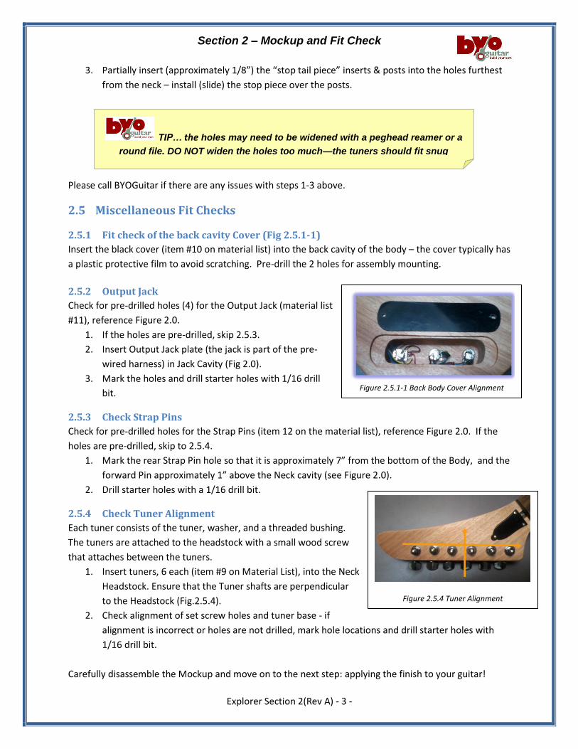
2.5.2 Output Jack
Check for pre-drilled holes (4) for the Output Jack (material list
#11), reference Figure 2.0.
1. If the holes are pre-drilled, skip 2.5.3.
2. Insert Output Jack plate (the jack is part of the pre-
wired harness) in Jack Cavity (Fig 2.0).
3. Mark the holes and drill starter holes with 1/16 drill
bit.
2.5.3 Check Strap Pins
Check for pre-drilled holes for the Strap Pins (item 12 on the material list), reference Figure 2.0. If the
holes are pre-drilled, skip to 2.5.4.
1. Mark the rear Strap Pin hole so that it is approximately 7” from the bottom of the Body, and the
forward Pin approximately 1” above the Neck cavity (see Figure 2.0).
2. Drill starter holes with a 1/16 drill bit.
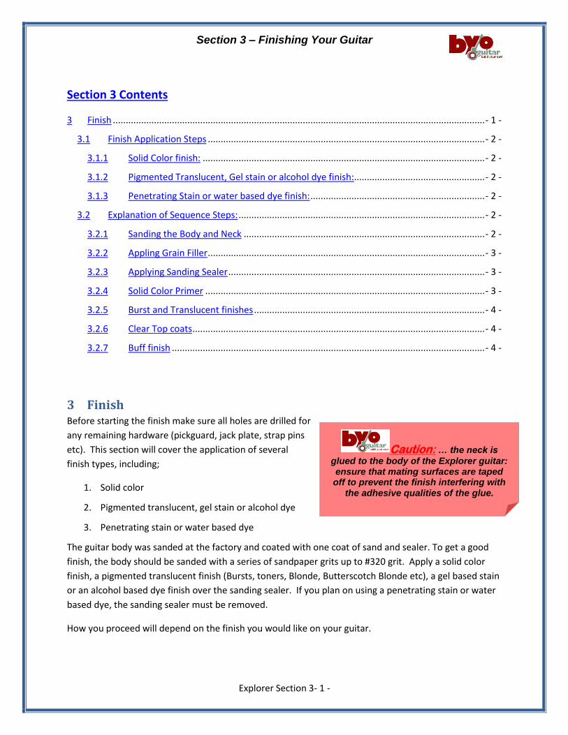
2.5.4 Check Tuner Alignment
Each tuner consists of the tuner, washer, and a threaded bushing.
The tuners are attached to the headstock with a small wood screw
that attaches between the tuners.
1. Insert tuners, 6 each (item #9 on Material List), into the Neck
Headstock. Ensure that the Tuner shafts are perpendicular
to the Headstock (Fig.2.5.4).
2. Check alignment of set screw holes and tuner base - if
alignment is incorrect or holes are not drilled, mark hole locations and drill starter holes with
1/16 drill bit.
Carefully disassemble the Mockup and move on to the next step: applying the finish to your guitar!
Figure 2.5.4 Tuner Alignment
TIP… the holes may need to be widened with a peghead reamer or a
round file. DO NOT widen the holes too much—the tuners should fit snug
.
Figure 2.5.1-1 Back Body Cover Alignment
Section 3 – Finishing Your Guitar
Explorer Section 3- 1 -
Section 3 Contents
3 Finish ................................................................................................................................................. - 1 -
3.1 Finish Application Steps ............................................................................................................ - 2 -
3.1.1 Solid Color finish: .............................................................................................................. - 2 -
3.1.2 Pigmented Translucent, Gel stain or alcohol dye finish:................................................... - 2 -
3.1.3 Penetrating Stain or water based dye finish: .................................................................... - 2 -
3.2 Explanation of Sequence Steps: ................................................................................................ - 2 -
3.2.1 Sanding the Body and Neck .............................................................................................. - 2 -
3.2.2 Appling Grain Filler ............................................................................................................ - 3 -
3.2.3 Applying Sanding Sealer .................................................................................................... - 3 -
3.2.4 Solid Color Primer ............................................................................................................. - 3 -
3.2.5 Burst and Translucent finishes .......................................................................................... - 4 -
3.2.6 Clear Top coats .................................................................................................................. - 4 -
3.2.7 Buff finish .......................................................................................................................... - 4 -
3 Finish Before starting the finish make sure all holes are drilled for
any remaining hardware (pickguard, jack plate, strap pins
etc). This section will cover the application of several
finish types, including;
1. Solid color
2. Pigmented translucent, gel stain or alcohol dye
3. Penetrating stain or water based dye
The guitar body was sanded at the factory and coated with one coat of sand and sealer. To get a good
finish, the body should be sanded with a series of sandpaper grits up to #320 grit. Apply a solid color
finish, a pigmented translucent finish (Bursts, toners, Blonde, Butterscotch Blonde etc), a gel based stain
or an alcohol based dye finish over the sanding sealer. If you plan on using a penetrating stain or water
based dye, the sanding sealer must be removed.
How you proceed will depend on the finish you would like on your guitar.
Caution: … the neck is
glued to the body of the Explorer guitar: ensure that mating surfaces are taped off to prevent the finish interfering with
the adhesive qualities of the glue.
Section 3 – Finishing Your Guitar
Explorer Section 3- 2 -
The following paragraphs outline several finishing processes, starting with the sequence for a finish type
(paragraph 3.1) followed by detailed explanation of each sequence step (paragraph 3.2).
3.1 Finish Application Steps
3.1.1 Solid Color finish:
1. Sand the body and neck
2. Apply grain filler if desired.
3. Apply 2 coats of sand and sealer
4. Sand to 320 grit
5. Apply primer
6. Sand the primer
7. Apply color coats
8. Apply clear top coats
9. Buff finish
3.1.2 Pigmented Translucent, Gel stain or alcohol dye finish:
1. Sand the body and neck
2. Apply grain filler if desired.
3. Apply 2 coats of sand and sealer
4. Sand to 320 grit
5. Apply stain or dye
6. Apply clear top coats
7. Buff finish
3.1.3 Penetrating Stain or water based dye finish:
1. Sand the body and neck to bare wood
2. Apply grain filler if desired.
3. Apply stain or dye
4. Apply 2 coats of sand and sealer
5. Sand to 320 grit
6. Apply clear top coats
7. Buff finish
3.2 Explanation of Sequence Steps:
3.2.1 Sanding the Body and Neck
1. Wear a NIOSH-approved respirator and ANSI-approved safety glasses when sanding wood!
2. Before starting the finish on the neck mask off the surface of the fingerboard.
TIP… re-open any of the screw holes in the body. Use a toothpick or small drill held between
your fingers to clean out any filler in the holes.
Section 3 – Finishing Your Guitar
Explorer Section 3- 3 -
3. Use a flexible sanding block with #150 grit aluminum-oxide sanding paper to sand the guitar
body until there is a consistent scratch pattern on the entire surface. Note: DO NOT round over
the neck pocket or the body cavities. When hand sanding, always sand in the same direction as
the wood grain.
4. Re-sand the entire guitar body and neck with #220 grit sanding paper and lightly round over the
outside edges of the body.
5. Wipe the guitar body and neck with a damp cloth to “raise" the wood grain.
6. Wait until the wood is dry and re-sand with #220 grit sandpaper to sand the “raised" grain
smooth.
(Note: On a maple fingerboard you can apply a clear finish to the entire neck and fingerboard. Apply
several coats and remove buildup on the frets between coats. An easy way to remove the finish buildup
on the frets is to take a nail and file a half round slot in the head about the same size as the frets. You
can then use this to easily scrape any finish build up.
If the neck has a Rosewood or Ebony fingerboard, be sure to tape off the fingerboard before applying
the finish. Behlen’s Fingerboard Oil is a great product for your fingerboard.)
3.2.2 Appling Grain Filler
Grain filler will fill in the grain and create flat surface. This is essential if you are trying to get a high gloss
finish. Oil based grain filler is recommended. We recommend using Behlen PORE-O-PAC grain filler. For
most finishes use natural colored filler. The dyes used in darker fillers may over time find their way
through the color coat.
Apply the filler by wiping across the grain. You can use a course cloth or your fingers to wipe the grain in.
After it has dried about ten to twenty minutes the excess can be removed with a cloth dampened with
mineral sprits. After about an hour repeat the process and let dry overnight. If you have removed most
of the excess with mineral spirits the remaining filler on the field of the wood can be sanded off (use
#220 again) in a few minutes. It is also a good idea at this time to reopen any of the screw holes in the
body. Use a toothpick or small drill held between your fingers to clean out any filler in the holes. The
body is now ready for a sand and sealer coating.
3.2.3 Applying Sanding Sealer
Sand and sealer is used to give the final coat a level base. It is also helpful in filling scratches which are
too deep to sand out. We recommend using Behlen Vinyl Sealer. This comes in aerosol cans and can
easily be sprayed on.
3.2.4 Solid Color Primer
The last step before applying the color coats is to apply a white primer coat. We recommend using Ohio
Valley Nitro Primer. The white background will also let you apply an opaque color coat with less paint.
Spray on two coats. When dry you may notice that the surface feels rough. Sand off the roughness with
#320 dry and respray. Sand again. If the surface now appears smooth and all grain is opaqued you are
ready for the color coat.
Section 3 – Finishing Your Guitar
Explorer Section 3- 4 -
3.2.5 Burst and Translucent finishes
Bursts and Translucent finishes can be applied using aerosol cans of lacquer toner. Ohio Valley Nitro
and Behlen have a full line of Nitrocellulose Lacquer Toners to achieve these finishes.
3.2.6 Clear Top coats
Apply several thin coats of the finish, following the manufacturer's instructions. Multiple thin coats
usually produce a better quality finish than one heavy coat. Dry sand the entire body with #400 grit wet
dry sandpaper after at least three coats of finish have been applied. DO NOT sand through the finish, be
careful on the edges. Use a tack cloth to remove sanding residue. Apply more finish, sanding between
coats, until the finish is the desired thickness.
3.2.7 Buff finish
When the final coat has dried at least a week, preferably a month, remove the masking. Wet sand the
finish using #600 grit wet/dry sandpaper with a sanding block, followed with #1000 grit wet/dry
sandpaper. Use a clean, absorbent rag to remove excess water. Let the guitar dry completely, then use
a tack cloth to remove all residue. Buff the finish by hand or with a buffer, starting with a medium polish
and working up to a high gloss polish.
Note: If you use a buffing machine, be careful to avoid going through the finish, especially on the edges.
Section 4 – Assembly
Explorer Section 4 - 1 -
Section 4 Contents:
4 Assembly ........................................................................................................................................... - 1 -
4.1 Installing the Neck ..................................................................................................................... - 2 -
4.1.1 Neck Positioning: Neck Cavity Insertion ........................................................................... - 2 -
4.1.2 Neck Positioning: Centering .............................................................................................. - 2 -
4.1.3 Neck positioning: neck angle ............................................................................................ - 3 -
4.1.4 Neck Installation: gluing in place ...................................................................................... - 3 -
4.2 Installation of the Electronic Components ............................................................................... - 4 -
4.2.1 Installing the Wiring Harness ............................................................................................ - 4 -
4.2.2 Install Neck Pickup ............................................................................................................ - 5 -
4.2.3 Install the Bridge pickup (Reference Figure 4.2) ............................................................... - 5 -
4.2.4 Selector Switch Wiring (Reference Figure 4.2) ................................................................. - 6 -
4.2.5 Install the Pickguard and Selector Switch ......................................................................... - 6 -
4.3 Installation of the Bridge Components ..................................................................................... - 7 -
4.3.1 Installing the Bridge .......................................................................................................... - 7 -
4.3.2 Installing the Tailpiece ...................................................................................................... - 7 -
4.4 Installing the Nut ....................................................................................................................... - 7 -
4.5 Installing the Tuners & Truss Rod Cover (Figure 4.5-1) ............................................................ - 8 -
4.5.1 Installing the Tuners .......................................................................................................... - 8 -
4.5.2 Installing the Truss Rod Cover ........................................................................................... - 8 -
4.6 Install the Strings....................................................................................................................... - 8 -
4.7 Installing the Strap Pins ............................................................................................................. - 8 -
4 Assembly
After your finish has been applied and thoroughly dried, we can now assemble your guitar. In this
section we will permanently install all of the components and solder the wiring for the bridge and neck
pickups. Remove all of the protective tape from neck and the neck cavity that you might have used
during the Finishing process.
TIP… use a blanket or large towel on your work area to protect your guitars’ finish
Section 4 – Assembly
Explorer Section 4 - 2 -
Bridge Saddle, top view Figure 4.1.1-3
Figure 4.1.1-1
Distance from Bridge to 12
th fret = Distance from 12
th fret to nut
Figure 4.1.1-2
Figure 4.1.2-1 Explorer Neck Centering
4.1 Installing the Neck
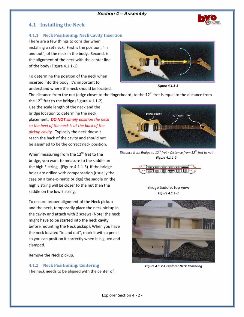
4.1.1 Neck Positioning: Neck Cavity Insertion
There are a few things to consider when
installing a set neck. First is the position, “in
and out”, of the neck in the body. Second, is
the alignment of the neck with the center line
of the body (Figure 4.1.1-1).
To determine the position of the neck when
inserted into the body, it’s important to
understand where the neck should be located.
The distance from the nut (edge closet to the fingerboard) to the 12th fret is equal to the distance from
the 12th fret to the bridge (Figure 4.1.1-2).
Use the scale length of the neck and the
bridge location to determine the neck
placement. DO NOT simply position the neck
so the heel of the neck is at the back of the
pickup cavity. Typically the neck doesn’t
reach the back of the cavity and should not
be assumed to be the correct neck position.
When measuring from the 12th fret to the
bridge, you want to measure to the saddle on
the high E string. (Figure 4.1.1-3) If the bridge
holes are drilled with compensation (usually the
case on a tune-o-matic bridge) the saddle on the
high E string will be closer to the nut then the
saddle on the low E string.
To ensure proper alignment of the Neck pickup
and the neck, temporarily place the neck pickup in
the cavity and attach with 2 screws (Note: the neck
might have to be started into the neck cavity
before mounting the Neck pickup). When you have
the neck located “in and out”, mark it with a pencil
so you can position it correctly when it is glued and
clamped.
Remove the Neck pickup.
4.1.2 Neck Positioning: Centering
The neck needs to be aligned with the center of
Section 4 – Assembly
Explorer Section 4 - 3 -
the pickup cavities and bridge. This step is the same if you are installing a set neck or a bolt
on neck. It’s important to get the correct neck alignment, as incorrect alignment of the neck results in
the E strings not running parallel to the edges of the fingerboard.
Clamp two straight boards to each side of the neck and use a ruler to align the neck with the center of
the bridge (figure 4.1.2-1). If the bridge holes are already drilled, the center is known. If they haven’t
been drilled, align with the center of the pickup cavities. Once you have located the neck, make a mark
on the heel of the bridge and pickup cavity so you align it when gluing and clamping.
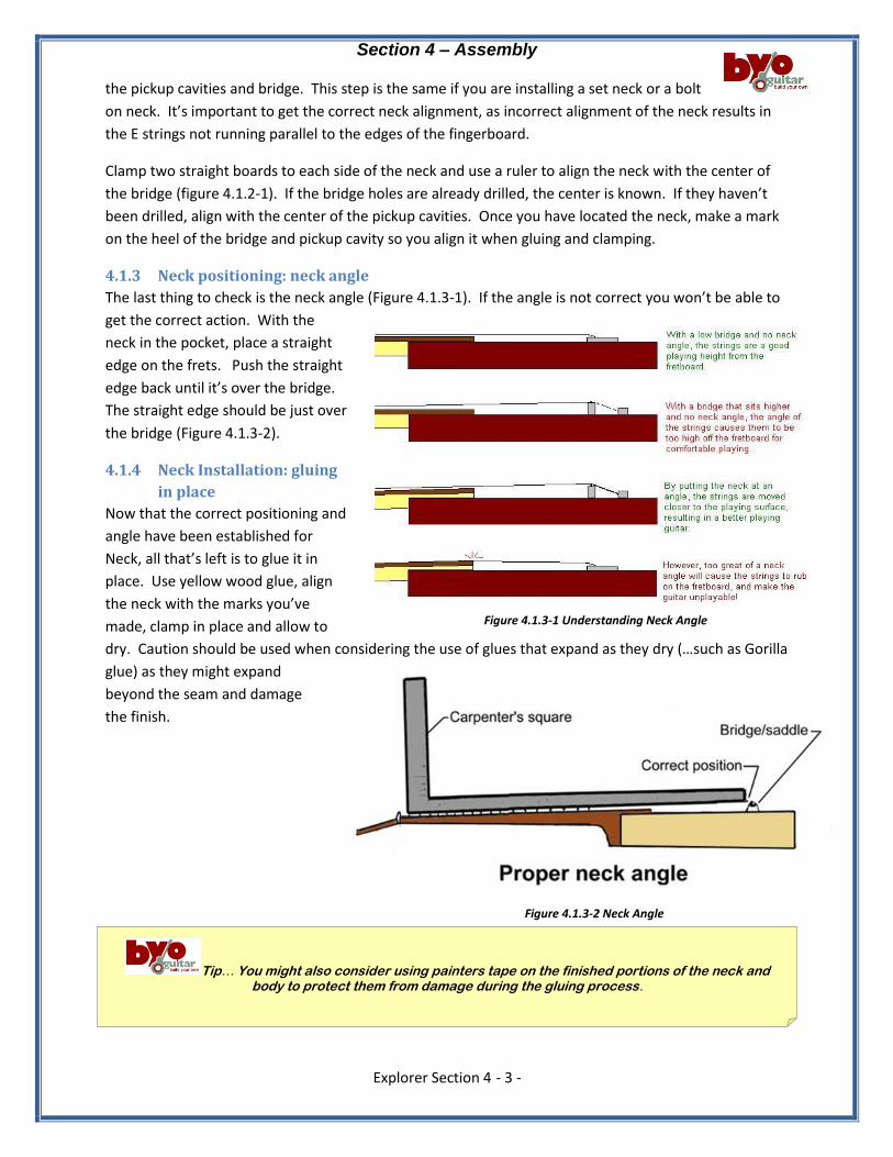
4.1.3 Neck positioning: neck angle
The last thing to check is the neck angle (Figure 4.1.3-1). If the angle is not correct you won’t be able to
get the correct action. With the
neck in the pocket, place a straight
edge on the frets. Push the straight
edge back until it’s over the bridge.
The straight edge should be just over
the bridge (Figure 4.1.3-2).
4.1.4 Neck Installation: gluing
in place
Now that the correct positioning and
angle have been established for
Neck, all that’s left is to glue it in
place. Use yellow wood glue, align
the neck with the marks you’ve
made, clamp in place and allow to
dry. Caution should be used when considering the use of glues that expand as they dry (…such as Gorilla
glue) as they might expand
beyond the seam and damage
the finish.
Figure 4.1.3-1 Understanding Neck Angle
Figure 4.1.3-2 Neck Angle
Tip… You might also consider using painters tape on the finished portions of the neck and body to protect them from damage during the gluing process.
Section 4 – Assembly
Explorer Section 4 - 4 -
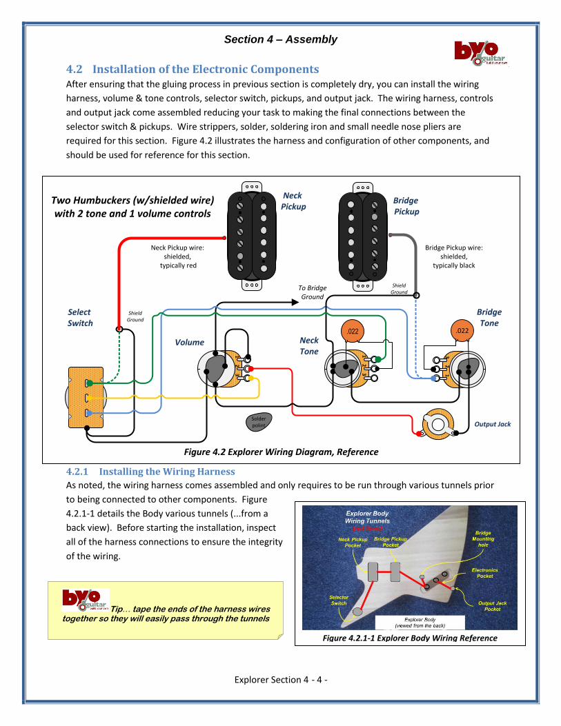
4.2 Installation of the Electronic Components After ensuring that the gluing process in previous section is completely dry, you can install the wiring
harness, volume & tone controls, selector switch, pickups, and output jack. The wiring harness, controls
and output jack come assembled reducing your task to making the final connections between the
selector switch & pickups. Wire strippers, solder, soldering iron and small needle nose pliers are
required for this section. Figure 4.2 illustrates the harness and configuration of other components, and
should be used for reference for this section.
4.2.1 Installing the Wiring Harness
As noted, the wiring harness comes assembled and only requires to be run through various tunnels prior
to being connected to other components. Figure
4.2.1-1 details the Body various tunnels (...from a
back view). Before starting the installation, inspect
all of the harness connections to ensure the integrity
of the wiring.
Figure 4.2 Explorer Wiring Diagram, Reference
.022 .022
Neck Pickup
Neck Pickup wire: shielded,
typically red
Bridge Pickup
Bridge Pickup wire: shielded,
typically black
BridgeTone
Volume NeckTone
Output Jack
Select Switch
To Bridge Ground
Two Humbuckers (w/shielded wire) with 2 tone and 1 volume controls
Shield Ground
Shield Ground
Solder polint
1 2
3
1 2
3
3 2
1
Figure 4.2.1-1 Explorer Body Wiring Reference
Tip… tape the ends of the harness wires together so they will easily pass through the tunnels

Section 4 – Assembly
Explorer Section 4 - 5 -
1. Carefully run the harness from the Electronic pocket to the Bridge pickup pocket.
2. Continue feeding the harness until the volume & tone controls are in the Electronics pocket.
a. Mount volume control first, ensuring that the bridge ground wire is inserted in the
channel to the bridge mounting post – use supplied washer & nut, do not tighten.
b. Mount tone controls (2) - use supplied washer & nut, do not tighten.
c. Mount output jack plate with supplied screws (4).
d. Mount output jack after carefully
inserting the jack through the
tunnel to the jack plate - use
supplied washer & nut – Figure
4.2.1-2.
e. Carefully tighten all controls in
place – take care of your finish!
3. Complete the harness installation.
a. Run the harness from the bridge
pocket to the neck pocket.
b. Run the harness from the neck pocket to the switch pocket.
4. Install the control knobs by turning all controls clock wise, then push on the control knobs with
the same orientation of the number scale, then install Electronics cover with supplied screws.
4.2.2 Install Neck Pickup
The pickups are installed as shown in Figure 4.2.2-
1 where the Neck pickup has a smaller taper than
the Bridge pickup. Also note that the pickups are
mounted with the small dimension of the taper
pointed toward the neck.
1. Run the shielded pickup wire from the
neck pocket to the switch pocket via the tunnel.
2. Mount the Neck pickup with 2 screws – do not tighten.
4.2.3 Install the Bridge pickup (Reference Figure 4.2)
1. Run the shielded pickup wire from the Bridge pocket to the electronics pocket via the tunnel.
(Note: unlike the straight Neck pickup tunnel, the Bridge tunnel has a corner as well as other
wires in place. Consider using something flexible yet strong (…ie a tie wrap, small straw) to first
run some string or fishing line through the tunnel – then attach the pickup wire to the fishing
line (…tape). Gently push the harness and pull the fishing line with the bridge pickup wire
through the tunnel).
2. Mount the Bridge pickup with 2 screws – do not tighten.
3. Solder the Bridge pickup shield (ground) to the case of the center potentiometer.
4. Solder in the Bridge pickup to pin 1 of the potentiometer closest to the back of the body – there
is a blue wire already connected to pin 1 (note: if the center conductor of the Bridge pickup
Figure 4.2.1-2 Completed Electronics Installation
Figure 4.2.2-1 Completed Electronics Installation
Section 4 – Assembly
Explorer Section 4 - 6 -
shielded wire does not reach the bridge tone control, solder an additional length of
wire to the center conductor and cover with shrink sleeve or electrical tape).
4.2.4 Selector Switch Wiring (Reference Figure 4.2)
The Selector switch allows you to choose either the Bridge pickup, the Neck pickup or both for output to
your amplifier.
1. Bridge input:
a. Trim & tin blue wire,
b. Solder to switch (check Fig. 4.2).
2. Switch output:
a. Trim & tin yellow wire,
b. Solder to switch (check Fig. 4.2).
3. Ground:
a. Trim & tin black wire (note: leave extra exposed wire for connecting Neck pickup shield
ground),
b. Solder to switch case terminal.
4. Neck input:
a. Trim & tin green wire,
b. Trim & tin the Neck center conductor,
c. Solder both to switch (check Fig. 4.2).
5. Neck shield/ground:
a. Trim & tin Neck shield ground,
b. Solder to the switch case ground (…the same point as in step #3 above).
4.2.5 Install the Pickguard and Selector Switch
Now that all of the wiring is complete, the next step is to mount the Selector switch on the pickguard
and mount the pickguard on the Body. Use caution when compressing the switch wires to fit into the
Switch pocket to ensure no wires are broken. Before starting, ensure that the clear protective film is
removed from the pickguard.
1. Mount the pickguard with 1 screw in a pickguard hole close to the back of the guitar, allowing
the pickguard to pivot over the switch pocket – do not tighten.
2. Slide/pivot the pickguard to allow the insertion of the Selector switch into the pickguard – then
insert and “snug up” the selector switch, leaving it loose enough to turn in the pickguard.
3. Pivot the pickguard so the selector switch is in the switch cavity – carefully compressing the wire
as you ensure that the green wire is closest to the Neck. The switch action should be near
parallel to the axis of the neck.
4. Tighten the switch in position.
5. Ensure the alignment of the Neck pickup, the Bridge pickup and the pickguard, then expose the
double sided tape on the rear of the pickguard and attach to the Body with supplied screws.
6. Secure the Neck & Bridge pickups with supplied screws.
Tip… “tinning” a wire: stripping off approximately ¼” of insulation, then applying solder
to the exposed wire to make soldering the final connection easier
Section 4 – Assembly
Explorer Section 4 - 7 -
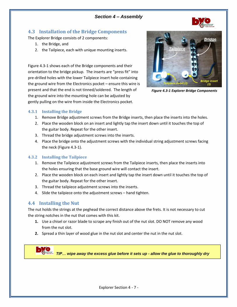
4.3 Installation of the Bridge Components The Explorer Bridge consists of 2 components:
1. the Bridge, and
2. the Tailpiece, each with unique mounting inserts.
Figure 4.3-1 shows each of the Bridge components and their
orientation to the bridge pickup. The inserts are “press fit” into
pre-drilled holes with the lower Tailpiece insert hole containing
the ground wire from the Electronics pocket – ensure this wire is
present and that the end is not tinned/soldered. The length of
the ground wire into the mounting hole can be adjusted by
gently pulling on the wire from inside the Electronics pocket.
4.3.1 Installing the Bridge
1. Remove Bridge adjustment screws from the Bridge inserts, then place the inserts into the holes.
2. Place the wooden block on an insert and lightly tap the insert down until it touches the top of
the guitar body. Repeat for the other insert.
3. Thread the bridge adjustment screws into the inserts.
4. Place the bridge onto the adjustment screws with the individual string adjustment screws facing
the neck (Figure 4.3-1).
4.3.2 Installing the Tailpiece
1. Remove the Tailpiece adjustment screws from the Tailpiece inserts, then place the inserts into
the holes ensuring that the base ground wire will contact the insert.
2. Place the wooden block on each insert and lightly tap the insert down until it touches the top of
the guitar body. Repeat for the other insert.
3. Thread the tailpiece adjustment screws into the inserts.
4. Slide the tailpiece onto the adjustment screws – hand tighten.
4.4 Installing the Nut The nut holds the strings at the peghead the correct distance above the frets. It is not necessary to cut
the string notches in the nut that comes with this kit.
1. Use a chisel or razor blade to scrape any finish out of the nut slot. DO NOT remove any wood
from the nut slot.
2. Spread a thin layer of wood glue in the nut slot and center the nut in the nut slot.
TIP… wipe away the excess glue before it sets up - allow the glue to thoroughly dry
Figure 4.3-1 Explorer Bridge Components
Section 4 – Assembly
Explorer Section 4 - 8 -
Assembly of your Guitar is now complete – let’s set it
up!!
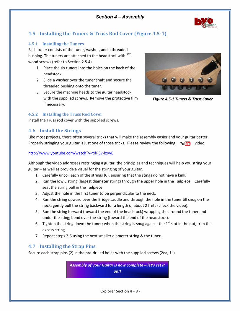
4.5 Installing the Tuners & Truss Rod Cover (Figure 4.5-1)
4.5.1 Installing the Tuners
Each tuner consists of the tuner, washer, and a threaded
bushing. The tuners are attached to the headstock with 3/8”
wood screws (refer to Section 2.5.4).
1. Place the six tuners into the holes on the back of the
headstock.
2. Slide a washer over the tuner shaft and secure the
threaded bushing onto the tuner.
3. Secure the machine heads to the guitar headstock
with the supplied screws. Remove the protective film
if necessary.
4.5.2 Installing the Truss Rod Cover
Install the Truss rod cover with the supplied screws.
4.6 Install the Strings Like most projects, there often several tricks that will make the assembly easier and your guitar better.
Properly stringing your guitar is just one of those tricks. Please review the following video:
http://www.youtube.com/watch?v=tIfP3v-bxwE
Although the video addresses restringing a guitar, the principles and techniques will help you string your
guitar – as well as provide a visual for the stringing of your guitar.
1. Carefully uncoil each of the strings (6), ensuring that the stings do not have a kink.
2. Run the low E string (largest diameter string) through the upper hole in the Tailpiece. Carefully
seat the string ball in the Tailpiece.
3. Adjust the hole in the first tuner to be perpendicular to the neck.
4. Run the string upward over the Bridge saddle and through the hole in the tuner till snug on the
neck; gently pull the string backward for a length of about 2 frets (check the video).
5. Run the string forward (toward the end of the headstock) wrapping the around the tuner and
under the sting; bend over the string (toward the end of the headstock).
6. Tighten the string down the tuner; when the string is snug against the 1st slot in the nut, trim the
excess string.
7. Repeat steps 2-6 using the next smaller diameter string & the tuner.
4.7 Installing the Strap Pins Secure each strap pins (2) in the pre-drilled holes with the supplied screws (2ea, 1”).
Figure 4.5-1 Tuners & Truss Cover
Section 5 – Setting Up Your Guitar
Explorer Section 5 - 1 -
Section 5 Contents:
5 Initial setup ....................................................................................................................................... - 1 -
5.1 Adjust the Guitar Neck: Truss Rod ............................................................................................ - 2 -
5.1.1 Check the Neck .................................................................................................................. - 2 -
5.1.2 Adjusting the Truss Rod .................................................................................................... - 2 -
5.2 String Lubrication ...................................................................................................................... - 2 -
5.3 Adjusting the Action .................................................................................................................. - 3 -
5.3.1 The Nut .............................................................................................................................. - 3 -
5.3.2 Bridge Saddle Adjustment................................................................................................. - 3 -
5.4 Pickup Height (Figure 5.4) ......................................................................................................... - 4 -
5.5 Intonation (Figure 5.5) .............................................................................................................. - 4 -
5.6 …Other Hints ............................................................................................................................. - 5 -
5 Initial setup In this section, we will address the initial setup for:
1. Adjusting the Neck (Truss Rod);
2. Adjusting the String Action (string height);
3. Adjusting the Pickup heights;
4. Adjusting the Intonation.
These adjustments will provide preliminary settings from which you can fine tune the sounds to your
individual playing style. As with previous sections, references are included for additional
clarification of specific adjustments.
String up the guitar with your desired gauge of strings – check the tuning.
reference…check out the following references that can be helpful in tuning your
guitar:
tone generator for tuning: http://www.get-tuned.com/online_guitar_tuner.php &
http://www.guitarforbeginners.com/onlinetuner.html
downloadable “musical instrument tuner” from PerfectPitch (http://www.nch.com.au/tuner/) that
will allow visualization of string adjustments
Section 5 – Setting Up Your Guitar
Explorer Section 5 - 2 -
5.1 Adjust the Guitar Neck: Truss Rod The first major procedure in the setup is adjusting the neck relief. Neck relief simply refers to how much
the neck bows. The degree of bowing in the neck is a matter of personal preference and is correlated to
your playing style.
5.1.1 Check the Neck
Get a ruler or straightedge that is at least as
long as the neck, but not so long that it
reaches all the way from the nut to the
saddles. If you can’t get one between these
lengths, and are willing to sacrifice a ruler, get
one that’s too long and cut it to length.
Alternatively, you can just cut a little out of
one edge so that you can still make full use of the other edge of the ruler. Now lay the edge of the ruler
along the frets (don’t rest it on top of the nut, saddles, pickups or pickup surrounds).
Using a feeler gauge or high resolution metal ruler, measure the string height (the gap between the
ruler/string and the top of the fret) at about the 8th fret. The string height should be approximately 1/8’
(0.012”) - simply slide the feeler gauge into the gap to see if it is too big/small.
5.1.2 Adjusting the Truss Rod
Tightening the truss rod adjustment bolt will cause the neck to warp backward (too much and the
strings will buzz on the frets), and loosening it will cause it to bow forward (giving more relief.).
CAUTION: If you find that the truss rod is very difficult to turn, then stop. It may be that there is a
problem with the neck or the truss rod and you may damage the guitar by forcing it.
Sight down the edge of the fingerboard from
behind the headstock, looking toward the body
of the guitar.
1. If the neck is too concave (action too
high), turn the truss rod nut clockwise to
remove excess relief (only adjust ¼ turn
at a time).
2. If the neck is too convex (strings too close to the fingerboard), turn the truss rod nut counter-
clockwise to allow the string tension to pull more relief into the neck.
3. Check the tuning, then re-check the gap with the feeler gauge and re-adjust as needed.
5.2 String Lubrication Lubricate the contact points of a string's travel to ensure tuning stability and reduce string breakage.
Lubricate:
1. string/saddle contact points with a light machine oil (…such as 3-in-1 oil because it contains
anti-rust and anti-corrosive properties) every time you change strings.
reference: …check out the following
references for adjusting the Truss rod:
http://www.youtube.com/watch?v=PHHepmTX3So
http://www.youtube.com/watch?v=4j3QryKIXrc)
TIP… do the neck adjustment in a series of
intermediate steps and re-tune your guitar before each
step – different tension on the strings changes the
adjustment of the neck
Section 5 – Setting Up Your Guitar
Explorer Section 5 - 3 -
2. string trees should also be lubricated; a small amount of lip balm applied with a toothpick works
well.
5.3 Adjusting the Action
5.3.1 The Nut
Setting the string action that is right for you
starts at the nut. The slots should already
be close, but you might want to make some adjustments.
1. Push the sixth string down between the second and third fret. The space between the first fret
and the bottom of the string should be about .006 or just about the thickness of two sheets of
paper. If the gap is wider than .006” you should deepen the slot with a small needle file. DO
NOT FILE TOO DEEP! Make sure when
you file, the file is angled down
toward the headstock. This will
ensure the string sits on the edge of
the nut closest to the fretboard.
2. Repeat the procedure for the
remaining 5 strings.
5.3.2 Bridge Saddle Adjustment
This will adjust the height of the strings over the 12th fret. Minor adjustments are made by raising or
lowering the bridge. This adjustment is a matter of personal preference. There should be a gradual
increase in height from the first string to the
sixth string.
The question here is how high to make the
bridge. This is personal choice.
Adjusting saddle height is very easy on the Explorer guitar. Since the bridge can only be adjusted at each
end, there is no need to adjust each saddle individually.
1. Check and, if necessary, adjust the low (thick) E string height. Do this by adjusting the height of
the bridge at the thick E string end. This is done by rotating the Bridge insert adjustment
counter-clockwise to raise the bridge or clockwise to lower it. Adjust the height until string
doesn’t buzz on any fret from being too low, but low enough that you can play up and down the
neck easily. There’s usually a sweet spot where you can just start to detect some buzzing and
you can leave it just a tiny bit higher than that. Be careful if you use a tool as it is easy to slip and
damage the finish on your guitar.
2. Now do the exact same procedure for the high (thin) E string end of the bridge.
reference…check out the following
references for adjusting the “Nut Action”:
http://www.youtube.com/watch?v=zz9UKX2lcxw
TIP…check out the following
references for adjusting the “Bridge Action Height”:
http://www.youtube.com/watch?v=oWpnW8ICn-U
TIP… most factories set action at 3/32" to
7/64" on the bass E string at the 12th fret and 2/32" to
5/64" on the treble E.

Section 5 – Setting Up Your Guitar
Explorer Section 5 - 4 -
Fig 5.4 Pickup Height Measurement
Table 5.4 Pickup Height Guide
Pickup 1st
String 6th
String
Bridge 2/64” 3/63”
Neck 3/64” 4/64”
Table 5.4 Bridge and Neck Pickup Heights
Fig 5.5 Intonation Adjustment
3. Play the guitar a little bit to see if any of the other strings are buzzing. If, say, the A string is still
buzzing, then raise up the end of the bridge nearest to that string a little bit.
5.4 Pickup Height (Figure 5.4) Each pickup is adjustable on the bass and treble sides. Finding the
best combination of tone and volume will require some
experimentation.
1 Bridge pickup:
1.1 Press the 1st string onto the last fret and hold;
1.2 Using a machinist ruler, measure the distance from
the top of the pole to the bottom of the 1st string –
note bass measurement;
1.3 Repeat #1.1 & #1.2 on the 6th string – note the treble
measurement;
2 Neck Pickup: repeat steps 1.1 through 1.3 (above) on the neck pickup, noting measured
heights.
Using Table 5.4 as a reference, adjust the height of the pickups by turning the adjustment screws for the
bridge, & neck pickups – recheck string
heights after each adjustment.
5.5 Intonation (Figure 5.5) Adjustments should be made after all of the
above have been accomplished.
1. Set the pickup selector switch in the
middle position.
2. Turn the volume & tone controls to
maximum.
3. Check tuning. Check each string at the 12th
fret, harmonic to fretted note (make sure
you are depressing the string evenly to the
fret, not the fingerboard).
reference…check out the following
for adjusting Intonation:
http://www.youtube.com/watch?v=CqN7xJD1rdE
Section 5 – Setting Up Your Guitar
Explorer Section 5 - 5 -
4. If sharp, lengthen the string by adjusting the saddle back. If flat, shorten the string by moving
the saddle forward.
5.6 …Other Hints There are a few other things that you can do to optimize your tuning stability:
1. Each time you play your guitar, before you do your final tuning, play for a few minutes to allow
the strings to warm up. Metal expands when warm and contracts when cool. After you've
played a few riffs, you can then do your final tuning;
2. Wipe the strings, neck and bridge with a lint-free cloth after playing;
3. When transporting or storing your guitar, even for short periods, avoid leaving it anyplace you
wouldn't feel comfortable yourself.
Remember, guitars are tempered instruments! Re-tune, play and make further adjustments as needed.
We hope you have enjoyed building your guitar! If you have any questions along the way please email
us at [email protected].