explosive safety submission amendment 1
TRANSCRIPT

Kaho`olawe Island Reserve UXO Clearance Project Explosive Safety Submission
Explosive Safety Submission Amendment 1
UXO Clearance Project Kaho`olawe Island Reserve, Hawaii
Contract No.: N62742-95-D-1369
Prepared for: Naval Facilities Engineering Command Pacific Division
Contracting Officer: Stan Louis
Prepared by: Parsons-UXB Joint Venture
November 2001
Kaho`olawe Island Reserve UXO Clearance Project Explosive Safety submission
Amendment 01 Page ii 11/06/01 Revision No.: 0
This page intentionally left blank

Kaho`olawe Island Reserve UXO Clearance Project Explosive Safety submission
Amendment 01 Page iii 11/06/01 Revision No.: 0
Table of Contents EXECUTIVE SUMMARY...............................................................................................................................1
SUMMARY ...................................................................................................................................................1 REASON FOR AMENDMENT ...........................................................................................................................1
Change in Clearance.............................................................................................................................2 Reformatted Explosive Safety Submission ...........................................................................................2
SECTION 1 REASON FOR OE ....................................................................................................................3 1.A PROJECT BACKGROUND .........................................................................................................................3 1.B TARGET HISTORY...................................................................................................................................3 1.C CLEARANCE HISTORY. ...........................................................................................................................3
SECTION 2 MAPS ........................................................................................................................................5 2.A REGIONAL MAP......................................................................................................................................5 2.B SITE MAPS .............................................................................................................................................5
2.b.(1) UXO Site Characterization.........................................................................................................5 2.b.(2) OE Removal Depth ....................................................................................................................5 2.b.(3) Explosive Storage and Transfer Facilities................................................................................11 2.b.(4) Demolition Areas Location .......................................................................................................14 2.b.(5) Existing and Planned Uses ......................................................................................................16
2.C QUANTITY-DISTANCE MAPS..................................................................................................................19 2.c.(1) OE Areas to be cleared Q-D Map ............................................................................................19 2.c.(2) Explosive Storage and Transfer Areas Q-D Map.....................................................................19 2.c.(3) Demolition Areas Q-D Map ......................................................................................................19
2.D SOIL SAMPLING MAPS...........................................................................................................................19
SECTION 3 AMOUNT AND TYPE OF OE .................................................................................................21 3.A SITE INVESTIGATION.............................................................................................................................21 3.B MOST PROBABLE MUNITION .................................................................................................................23 3.C EXPLOSIVE CONTAMINATED SOIL..........................................................................................................24 3.D EXPLOSIVE CONTAMINATED BUILDINGS.................................................................................................24
SECTION 4 START DATE..........................................................................................................................25 4.A PROJECT HISTORY...............................................................................................................................25 4.B PROJECT DURATION.............................................................................................................................26
SECTION 5 FROSTLINE ............................................................................................................................27
SECTION 6 CLEARANCE TECHNIQUES .................................................................................................29 6.A UXO DETECTION AND CLEARANCE METHODS .......................................................................................29
6.a.(1) Area Pre-investigation..............................................................................................................29 6.a.(2) Grid Map Units .........................................................................................................................29 6.a.(3) Area Assessment .....................................................................................................................31 6.a.(4) Assessment Review.................................................................................................................32 6.a.(5) Area Preparation ......................................................................................................................32 6.a.(6) Tier I (Surface) UXO Clearance Operations ............................................................................33 6.a.(7) Tier II (Subsurface) UXO Clearance Operations .....................................................................34 6.a.(8) Anomaly Review ......................................................................................................................35 6.a.(9) Excavation................................................................................................................................35 6.a.(10) UXO/OE Identification and Assessment ................................................................................36
Kaho`olawe Island Reserve UXO Clearance Project Explosive Safety submission
Amendment 01 Page iv 11/06/01 Revision No.: 0
Table of Contents (Continued) 6.B METHOD OF DETECTION.......................................................................................................................36
6.b.(1) Detector Selection....................................................................................................................37 6.b.(2) Detector Validation Process.....................................................................................................42 6.b.(3) Detector Limitations .................................................................................................................48 6.b.(4) Geonics EM-61 Specifications .................................................................................................49 6.b.(5) GTL TM-5emu Specifications ..................................................................................................51
6.C QUALITY ASSURANCE/QUALITY CONTROL (QA/QC) ..............................................................................51 6.c.(1) QA/QC Program Overview.......................................................................................................52 6.c.(2) Process Control........................................................................................................................52 6.c.(3) Quality Acceptance Methodology.............................................................................................53 6.c.(4) Data Validation .........................................................................................................................53
6.D OE SCRAP PROCESSING......................................................................................................................53 6.d.(1) Material Types..........................................................................................................................53 6.d.(2) Processing and Treatment.......................................................................................................54
6.E DISPOSITION OF OE SCRAP .................................................................................................................55
SECTION 7 ALTERNATE TECHNIQUES..................................................................................................57
SECTION 8 QUANTITY-DISTANCE ..........................................................................................................59 8.A OE AREAS ..........................................................................................................................................59
8.a.(1) OE Work Areas ........................................................................................................................59 8.a.(2) Preliminary Site Work...............................................................................................................61
8.B EXPLOSIVE STORAGE AND TRANSFER LOCATION...................................................................................61 8.b.(1) Explosive Holding Area (EHA) .................................................................................................61 8.b.(2) Open Storage Area (OSA) .......................................................................................................64 8.b.(3) Inspection Point........................................................................................................................64 8.b.(4) Ammunition Transfer Point (ATP) ............................................................................................64
8.C PLANNED OR ESTABLISHED DEMOLITION AREAS....................................................................................64 8.c.(1) Open Burn Site.........................................................................................................................64 8.c.(2) Open Detonation Pits ...............................................................................................................64 8.c.(3) Thermal Processing Unit ..........................................................................................................64
8.D FOOTPRINT AREAS...............................................................................................................................65 8.d.(1) Blow-in-Place ...........................................................................................................................65 8.d.(2) Collection Points ......................................................................................................................66 8.d.(3) In-Grid Consolidated Shots......................................................................................................66
SECTION 9 OFF-SITE DISPOSAL.............................................................................................................67
SECTION 10 TECHNICAL SUPPORT .......................................................................................................69 10.A GOVERNMENT AGENCIES ...................................................................................................................69
10.a.(1) Commander Naval Base Pearl Harbor ..................................................................................69 10.a.(2) Pacific Division, Naval Facilities Engineering Command.......................................................69 10.a.(3) Naval Explosive Ordnance Disposal Technology Division ....................................................71 10.a.(4) State of Hawaii .......................................................................................................................71
10.B PARSONS-UXB (PUXB) JOINT VENTURE............................................................................................72 10.b.(1) PUXB Background .................................................................................................................73 10.b.(2) PUXB Organization................................................................................................................73 10.b.(3) PUXB Management ...............................................................................................................73 10.b.(4) PUXB Management Offices ...................................................................................................74

Kaho`olawe Island Reserve UXO Clearance Project Explosive Safety submission
Amendment 01 Page v 11/06/01 Revision No.: 0
Table of Contents (Continued)
SECTION 11 LAND USE RESTRICTIONS ................................................................................................75 11.A INTRODUCTION...................................................................................................................................75 11.B STATE OF HAWAII ACCESS AND RISK MANAGEMENT PLAN ...................................................................75
11.b.(1) Designated Use Areas ...........................................................................................................75 11.b.(2) Types of Authorized Access ..................................................................................................75 11.b.(3) Administrative and Operational Requirements ......................................................................75 11.b.(4) Access Guide Requirements .................................................................................................76 11.b.(5) Authorized Activities...............................................................................................................76 11.b.(6) Boundary Marking Mechanism. .............................................................................................76 11.b.(7) Reserve Monitoring................................................................................................................76 11.b.(8) Legal and Statutory Control Mechanisms..............................................................................76 11.b.(9) Institutional Control Program Matrix.......................................................................................76
11.C NAVY-PROVIDED INSTITUTIONAL CONTROLS .......................................................................................76 11.c.(1) Land Use Restrictions ............................................................................................................76 11.c.(2) Restrictive Covenants ............................................................................................................79 11.c.(3) Coastal Warning Signs...........................................................................................................79 11.c.(4) Boundary Markers ..................................................................................................................79 11.c.(5) Site-Specific Institutional Controls..........................................................................................87
11.D MONITORING/ENFORCEMENT OF INSTITUTIONAL CONTROLS.................................................................87 11.E REMOVAL/MODIFICATION OF INSTITUTIONAL CONTROLS.......................................................................87
SECTION 12 PUBLIC INVOLVEMENT......................................................................................................89 12.A PUBLIC PARTICIPATION AGREEMENT...................................................................................................89 12.B PUBLIC MEETING ...............................................................................................................................89 12.C KAHO`OLAWE CLEANUP PLAN PUBLIC REVIEW ....................................................................................89 12.D ADMINISTRATIVE RECORD ..................................................................................................................89
SECTION 13 REFERENCES......................................................................................................................91

Kaho`olawe Island Reserve UXO Clearance Project Explosive Safety submission
Amendment 01 Page vi 11/06/01 Revision No.: 0
List of Tables TABLE 1. KAHO`OLAWE'S UXO RELATED HISTORY.............................................................................................4 TABLE 2. UXO CLEARANCE TIER CHART ..........................................................................................................9 TABLE 3. LAND USE COMPARISON TABLE .......................................................................................................17 TABLE 4. ORDNANCE COMMONLY FOUND ON KAHO`OLAWE ISLAND .................................................................21 TABLE 5. MINIMUM TIER I CLEARANCE CRITERIA.............................................................................................33 TABLE 6. UXO DETECTION REQUIREMENTS FOR TIER II CLEARANCE...............................................................35 TABLE 7. DETECTOR SELECTION ....................................................................................................................36 TABLE 8. UXO DETECTION SYSTEMS (< 4 FEET)............................................................................................40 TABLE 9. UXO DETECTION SYSTEMS (> 4 FEET)............................................................................................40 TABLE 10. CONFIDENCE LEVELS FOR N = 20 THROUGH N = 100, PD=85% .......................................................44 TABLE 11. SUBSURFACE QC RANGE TARGET ITEMS .......................................................................................46 TABLE 12. SUMMARY OF BURIED TARGETS .....................................................................................................46 TABLE 13. CALCULATED FRAGMENTATION DISTANCES FOR SOME ORDNANCE FOUND ON KAHO`OLAWE............62 TABLE 14. TNT EQUIVALENT WEIGHT RATIOS FOR EXPLOSIVE MATERIALS......................................................63 TABLE 15. CUBE ROOTS OF EXPLOSIVE WEIGHTS...........................................................................................63 TABLE 16. SITE-SPECIFIC INSTITUTIONAL CONTROLS MATRIX..........................................................................88
List of Figures FIGURE 1. UXO CLEARANCE PROCESS ..........................................................................................................30 FIGURE 2. GRID MAP UNIT .............................................................................................................................31 FIGURE 3. APPLICABLE UXO CLEARANCE METHODOLOGY ..............................................................................38 FIGURE 4. JPG TARGETS DETECTED .............................................................................................................42 FIGURE 5. MODEL PROJECT TARGETS DETECTED...........................................................................................42 FIGURE 6. SUBSURFACE QC RANGE LAYOUT .................................................................................................45 FIGURE 7. GEONICS EM-61 DIAGRAM ............................................................................................................50 FIGURE 8. GTLTM-5EMU...............................................................................................................................52 FIGURE 9. AREAS AND ZONES ........................................................................................................................60 FIGURE 10. PACNAVFACENGCOM – ROICC KAHO`OLAWE ORGANIZATIONAL STRUCTURE.........................70 FIGURE 11. PUXB TEAM MEMBER ORGANIZATIONAL STRUCTURE..................................................................73 FIGURE 12. STATE OF HAWAII INSTITUTIONAL CONTROL PROGRAM MATRIX .....................................................77 FIGURE 13. COASTAL WARNING SIGNS...........................................................................................................79 FIGURE 14. TYPICAL TYPE 1 BOUNDARY MARKER FOR LEVEL 1 AREAS ...........................................................80 FIGURE 15: TYPICAL TYPE 2 BOUNDARY MARKERS FOR ROADS AND HELICOPTER LANDING ZONES ..................81 FIGURE 16. TYPICAL TYPE 2B BOUNDARY MARKERS FOR TRAILS....................................................................82 FIGURE 17. TYPE 2C BOUNDARY MARKERS FOR REVEGETATION AREAS .........................................................84 FIGURE 18. EXAMPLE APPLICATION OF TYPE 2C RESTORATION AREA MARKERS .............................................84 FIGURE 19. TYPE 4 BOUNDARY MARKER FOR UNCLEARED AREAS...................................................................85
List of Maps MAP 1. REGIONAL LOCATION MAP....................................................................................................................6 MAP 2. OE AREAS – SURFACE RAC................................................................................................................7 MAP 3. OE AREAS – SUBSURFACE RAC..........................................................................................................8 MAP 4. OE REMOVAL DEPTHS .......................................................................................................................12 MAP 5. EXPLOSIVE STORAGE AND TRANSFER FACILITIES ................................................................................13 MAP 6. DEMOLITION AREAS LOCATION ...........................................................................................................15 MAP 7. PROPOSED LAND USE........................................................................................................................18

Kaho`olawe Island Reserve UXO Clearance Project Explosive Safety submission
Amendment 01 Page 1 11/06/01 Revision No.: 0
Executive Summary
Summary In accordance with the Department of Defense (DoD) Standard 6055.9 and the Department of Defense, Explosive Safety Board (DDESB) memorandum of 27 January 1998, this Explosive Safety Submission is submitted for the Unexploded Ordnance (UXO) Cleanup of the Kaho`olawe Island Reserve, Hawaii. Kaho`olawe is the smallest of the eight main islands in the Hawaiian Archipelago, 94 miles southwest of Honolulu. Kaho`olawe is 11 miles long, 6 miles wide and contains approximately 28,800 acres. The island is of volcanic origin with elevations of 1,477 feet. The slopes are fissured with gulches 50 to 200 feet deep. Approximately 30 percent of the island is barren due to severe erosion. Formidable cliffs dominate the east and south coast. Title X of Fiscal Year (FY) 1994 Department of Defense (DoD) Appropriations Act directed the United States of America, through the Secretary of the Navy, to convey Kaho`olawe to the State of Hawaii and to enter into an Memorandum of Understanding (MOU) regarding the cleanup of the island. On May 6, 1994, the Navy signed an MOU with the State of Hawaii establishing a basic framework to accomplish the Kaho`olawe Island cleanup. Title for the land was conveyed to Hawaii on May 9, 1994, but access control remains with the Navy until UXO cleanup operations are complete or 11 November 2003, whichever occurs first. Title X requires the “establishment of a two-tiered standard of restoration and ordnance clearance, removal, restoration, and safety, taking into account the purpose for which any geographic area will be used and the nature and purpose of human access to such area, but assuring the protection of human health and the environment.” The MOU developed two UXO clearance standards – Tier I and Tier II. The Tier I standard was defined as clearance of all UXO from the surface of the island. The MOU states that the Cleanup Plan “shall provide for the removal or clearance of all unexploded ordnance from the surface of the island in accordance with Tier I standard.” The Tier II standard was identified in the MOU as the “cleanup or environmental restoration to a condition which allows the reasonably safe use of the site or area” for the purposes listed in the Kaho`olawe Use Plan. The Kaho`olawe Use Plan has been prepared to identify intended use and priority areas that are to be cleared to the Tier I and Tier II standards. For the purpose of this Explosive Safety Submission, Tier II has been defined as UXO clearance of the surface plus four feet below the surface. Ordnance and explosives (OE) clearance activities began on December 7, 1997, and are planned to extend through November 2003.
Reason for Amendment Amendment 1 of the Explosive Safety Submission for the Unexploded Ordnance (UXO) Cleanup of Kaho`olawe Island Reserve, Hawaii is required to document the following changes:
• = A change in clearance, which changes the planned reuse
• = Reformat of the previous Explosive Safety Submission to conform to DDESB guidance of January 1998
Kaho`olawe Island Reserve UXO Clearance Project Explosive Safety submission
Amendment 01 Page 2 11/06/01 Revision No.: 0
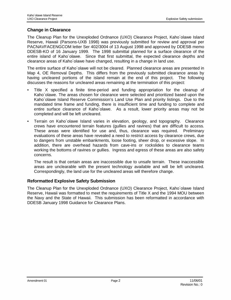
Change in Clearance The Cleanup Plan for the Unexploded Ordnance (UXO) Clearance Project, Kaho`olawe Island Reserve, Hawaii (Parsons-UXB 1998) was previously submitted for review and approval per PACNAVFACENGCOM letter Ser 402/3004 of 13 August 1998 and approved by DDESB memo DDESB-KO of 16 January 1999. The 1998 submittal planned for a surface clearance of the entire island of Kaho`olawe. Since that first submittal, the expected clearance depths and clearance areas of Kaho`olawe have changed, resulting in a change in land use. The entire surface of Kaho`olawe will not be cleared. Planned clearance areas are presented in Map 4, OE Removal Depths. This differs from the previously submitted clearance areas by having uncleared portions of the island remain at the end of this project. The following discusses the reasons for uncleared areas remaining at the termination of this project:
• = Title X specified a finite time-period and funding appropriation for the cleanup of Kaho`olawe. The areas chosen for clearance were selected and prioritized based upon the Kaho`olawe Island Reserve Commission’s Land Use Plan and priority listings. Due to the mandated time frame and funding, there is insufficient time and funding to complete and entire surface clearance of Kaho`olawe. As a result, lower priority areas may not be completed and will be left uncleared.
• = Terrain on Kaho`olawe Island varies in elevation, geology, and topography. Clearance crews have encountered terrain features (gullies and ravines) that are difficult to access. These areas were identified for use and, thus, clearance was required. Preliminary evaluations of these areas have revealed a need to restrict access by clearance crews, due to dangers from unstable embankments, loose footing, sheer drop, or excessive slope. In addition, there are overhead hazards from cave-ins or rockslides to clearance teams working the bottoms of ravines or gullies. Ingress and egress of these areas are also safety concerns. The result is that certain areas are inaccessible due to unsafe terrain. These inaccessible areas are unclearable with the present technology available and will be left uncleared. Correspondingly, the land use for the uncleared areas will therefore change.
Reformatted Explosive Safety Submission The Cleanup Plan for the Unexploded Ordnance (UXO) Clearance Project, Kaho`olawe Island Reserve, Hawaii was formatted to meet the requirements of Title X and the 1994 MOU between the Navy and the State of Hawaii. This submission has been reformatted in accordance with DDESB January 1998 Guidance for Clearance Plans.
Kaho`olawe Island Reserve UXO Clearance Project Explosive Safety submission
Amendment 01 Page 3 11/06/01 Revision No.: 0
Section 1 Reason for OE A brief description of why OE exists in the specific area(s) covered by this submission.
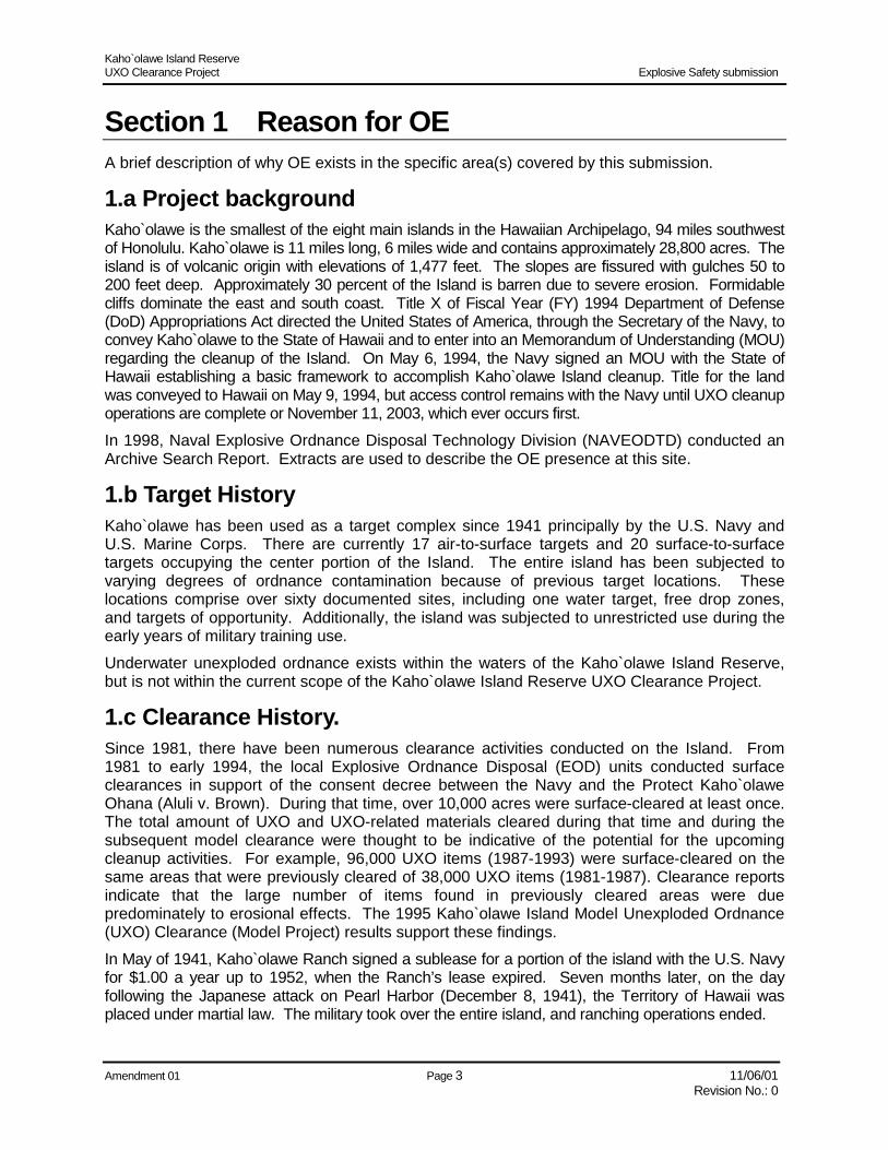
1.a Project background Kaho`olawe is the smallest of the eight main islands in the Hawaiian Archipelago, 94 miles southwest of Honolulu. Kaho`olawe is 11 miles long, 6 miles wide and contains approximately 28,800 acres. The island is of volcanic origin with elevations of 1,477 feet. The slopes are fissured with gulches 50 to 200 feet deep. Approximately 30 percent of the Island is barren due to severe erosion. Formidable cliffs dominate the east and south coast. Title X of Fiscal Year (FY) 1994 Department of Defense (DoD) Appropriations Act directed the United States of America, through the Secretary of the Navy, to convey Kaho`olawe to the State of Hawaii and to enter into an Memorandum of Understanding (MOU) regarding the cleanup of the Island. On May 6, 1994, the Navy signed an MOU with the State of Hawaii establishing a basic framework to accomplish Kaho`olawe Island cleanup. Title for the land was conveyed to Hawaii on May 9, 1994, but access control remains with the Navy until UXO cleanup operations are complete or November 11, 2003, which ever occurs first. In 1998, Naval Explosive Ordnance Disposal Technology Division (NAVEODTD) conducted an Archive Search Report. Extracts are used to describe the OE presence at this site.
1.b Target History Kaho`olawe has been used as a target complex since 1941 principally by the U.S. Navy and U.S. Marine Corps. There are currently 17 air-to-surface targets and 20 surface-to-surface targets occupying the center portion of the Island. The entire island has been subjected to varying degrees of ordnance contamination because of previous target locations. These locations comprise over sixty documented sites, including one water target, free drop zones, and targets of opportunity. Additionally, the island was subjected to unrestricted use during the early years of military training use. Underwater unexploded ordnance exists within the waters of the Kaho`olawe Island Reserve, but is not within the current scope of the Kaho`olawe Island Reserve UXO Clearance Project.
1.c Clearance History. Since 1981, there have been numerous clearance activities conducted on the Island. From 1981 to early 1994, the local Explosive Ordnance Disposal (EOD) units conducted surface clearances in support of the consent decree between the Navy and the Protect Kaho`olawe Ohana (Aluli v. Brown). During that time, over 10,000 acres were surface-cleared at least once. The total amount of UXO and UXO-related materials cleared during that time and during the subsequent model clearance were thought to be indicative of the potential for the upcoming cleanup activities. For example, 96,000 UXO items (1987-1993) were surface-cleared on the same areas that were previously cleared of 38,000 UXO items (1981-1987). Clearance reports indicate that the large number of items found in previously cleared areas were due predominately to erosional effects. The 1995 Kaho`olawe Island Model Unexploded Ordnance (UXO) Clearance (Model Project) results support these findings. In May of 1941, Kaho`olawe Ranch signed a sublease for a portion of the island with the U.S. Navy for $1.00 a year up to 1952, when the Ranch’s lease expired. Seven months later, on the day following the Japanese attack on Pearl Harbor (December 8, 1941), the Territory of Hawaii was placed under martial law. The military took over the entire island, and ranching operations ended.

Kaho`olawe Island Reserve UXO Clearance Project Explosive Safety submission
Amendment 01 Page 4 11/06/01 Revision No.: 0
Ship-to-shore bombardment of the island commenced in 1941 and intensified starting on October 21, 1943, when the USS Pennsylvania conducted rehearsals for the Gilbert Islands invasion. In preparation for additional landings across the Pacific, the Navy ran ship-to-shore fire-control training operations at Kaho`olawe. From 1942-1943, American submarine commanders tested torpedoes by firing them at the shoreline cliffs at Kanapou. Additional torpedoes were test-fired from 1943 to the 1960’s. The following summary (Table 1) is a brief synopsis of Kaho`olawe's UXO-related history:
Table 1. Kaho`olawe's UXO related history Date Event
1941 Kaho`olawe was subleased to the U.S. Government by the Kaho`olawe Ranch company for use as a military training area.
1953 President Eisenhower signed an Executive Order on 20 February (No. 10136, 25 February) placing the control of the Island under the Secretary of the Navy.
1965 "Sailor Hat" tests were conducted on Kaho`olawe. Three tests of 500 tons of TNT each were detonated to simulate the blast effects of nuclear weapons on shipboard weapon systems.
1969 The center third of the Island was designated as the impact area, the remainder as troop safety zones.
1976-77 The last major road and target upgrades were made.
1976 Ironwood trees (200) were planted to create a windbreak. Follow-on planting of Tamarisk pines was conducted in the 1980's. Twelve permanent signs were erected at most likely landing sites. An underwater survey was conducted by local Navy EOD unit
1977 “Puff” rounds (non-explosive ordnance with a spotting charge) were introduced.
1978 An M83 “butterfly” bomb was found behind galley at the Navy base camp. Prior to this time, there was no recorded usage of this type weapon system near base camp.
1980 The DoD was taken to court through the Hawaii Legal Aid Society. The resulting consent decree, Aluli v. Brown, set forth-specific responsibilities and deadlines to be met by the DoD, state and local agencies. Public Law 96-418 dated 10 October, section 810(a) initiated a Decontamination Study requirement for Kaho`olawe Island.
1981 The entire Island was designated as Kaho`olawe Island Archaeological District and was listed on the National Register of Historic Places. Surface clearance operations were initiated in accordance with the Consent Agreement. (Table 1) 1989: During road grading of K1 (and Location: 45407231), three AN-M30 series HE GP 100 bombs were found by the graders.
1990 Presidential memo of 22 October 1990 immediately ceased use of Kaho`olawe as a live ordnance training area.
1993 A State underwater study was completed.
1994 Title X of FY 1994 DoD Appropriations Act directed that the United States of America, through the Secretary of the Navy, convey the Island and its surrounding waters to the State of Hawaii and enter into a MOU regarding the cleanup of the Island. On 6 May 1994 the Navy signed an MOU with the State of Hawaii establishing a basic framework to accomplish Kaho`olawe Island cleanup. Title for the land was conveyed to the State on 9 May 1994, but access control remains with the Navy until UXO cleanup operations are complete or until 11 November 2003, whichever occurs first.
1994 Base Camp was surface-swept in preparation of the follow-on contract efforts
1995-96 The Model Action Plan (MAP) UXO clearance was performed.
1997 The Omnibus UXO clearance contract awarded. A site investigation for UXO was completed.

Kaho`olawe Island Reserve UXO Clearance Project Explosive Safety submission
Amendment 01 Page 5 11/06/01 Revision No.: 0
Section 2 Maps 2.a Regional Map Kaho`olawe Island is located 151.3 km (94 miles) southeast of Oahu and 9.7 km (6 miles) southwest of Maui. The Kaho`olawe Island Reserve includes the island and waters extending seaward 3.2 km (2 nautical miles) from the shoreline. Map 1 locates Kaho`olawe Island within the State of Hawaii.
2.b Site maps 2.b.(1) UXO Site Characterization NAVEODTD has developed two UXO Site characterization maps. The first (Map 2) delineates the various Surface Risk Assessment Codes (RACs). The second (Map 3) delineates the various Subsurface RACs. The Surface and Subsurface RACs were developed in the following manner (NAVEODTD March 1998). The UXO site characterization combines a variety of information into estimates of surface-hazard areas and estimated subsurface densities. The surface-hazard areas and estimated subsurface densities were extracted from previously surface-swept areas compiled for clearance reports from 1981-1994; Kaho`olawe Island Target Locations (May 1995); previous Preliminary Hazard Assessments and the 1997 Site Investigation; and the Model Clearance (September 1995 to January 1996). In each instance, the data was combined and evaluated as a whole to assess a specific area at a specific level. Boundaries of the areas were identified by their own unique way-points from the site investigation and adjusted to account for previously cleared areas. Additionally, surface and subsurface hazard severity (HS) was adjusted to account for the interpreted erosional effects within the respective areas. Subsurface density levels were extended downhill into major gulches, because of the tremendous effect water erosion has when focused and consolidated into the major gulches. Surface hazard levels were extended downhill in some instances when UXO or UXO remnants were documented. The resultant surface and subsurface HS maps show high hazard areas are associated with targets and target complexes. Several other highly contaminated areas may be presumptive targets or targets of opportunity. No area on the island is free from some degree of ordnance contamination.
2.b.(2) OE Removal Depth The Kaho`olawe Use Plan (PBR Hawaii 1995) provided general guidance to the Navy in developing the Cleanup Plan (Parsons-UXB 1998). The Kaho`olawe Use Plan establishes an overall vision for the future use of Kaho`olawe, describes guiding principles of land use, and identifies uses, activities, and certain infrastructure consistent with the vision and guiding principles. Priority areas and levels of clearance were established in accordance with the guidance found in Title X, MOU, and Regulatory Framework (Department of the Navy 1994) and were designed to allow reasonably safe use for the listed purpose of each area, as identified in the Kaho`olawe Use Plan (ibid.) and further defined in the Kaho`olawe Island Reserve Commission’s Priorities and Sequencing Plan (KIRC 2001).
Kaho`olawe Island Reserve UXO Clearance Project Explosive Safety submission
Amendment 01 Page 6 11/06/01 Revision No.: 0
Map 1. Regional Location Map See oversized drawing “Map 1:Regional Location Map”
Or attached Autocad file: MAP 1 REGIONAL LOCATION PLAN.DWG
Kaho`olawe Island Reserve UXO Clearance Project Explosive Safety submission
Amendment 01 Page 7 11/06/01 Revision No.: 0
Map 2. OE Areas – Surface RAC See oversized drawing “Map 2: OE Areas – Surface RAC”
Or attached Autocad file: MAP 2 OE AREAS - SURFACE RAC.DWG

Kaho`olawe Island Reserve UXO Clearance Project Explosive Safety submission
Amendment 01 Page 8 11/06/01 Revision No.: 0
Map 3. OE Areas – Subsurface RAC See oversized drawing: Map 3: OE Areas – Subsurface RAC”
Or attached Autocad file: MAP 3 OE AREAS - SUBSURFACE RAC.DWG

Kaho`olawe Island Reserve UXO Clearance Project Explosive Safety submission
Amendment 01 Page 9 11/06/01 Revision No.: 0
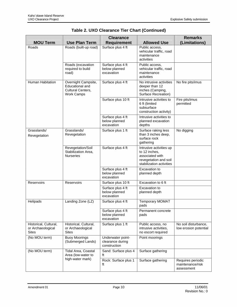
The Cleanup Plan took into account the proposed uses of the land described in the Kaho`olawe Use Plan to define the timing, planning, methodology, technologies, implementation of operations; cleanup of hazardous and other waste; and protection of historical, cultural, and religious sites, features, and artifacts from the clearance activities planned for the removal of unexploded ordnance and environmental restoration of Kaho`olawe Island Reserve. Title X requires the “establishment of a two-tiered standard of restoration and ordnance clearance, removal, restoration and safety, taking into account the purpose for which any geographic area will be used and the nature and purpose of human access to such area, but assuring the protection of human health and the environment.” The MOU developed two UXO-clearance standards – Tier I and Tier II. The Tier I standard was defined as clearance of all UXO from the surface of the island. The MOU states that the Cleanup Plan “shall provide for the removal or clearance of all unexploded ordnance from the surface of the island in accordance with Tier I standard.” The Tier II standard was identified in the MOU as the “cleanup or environmental restoration to a condition which allows the reasonably safe use of the site or area” for the purposes listed in the Kaho`olawe Use Plan.” The Use Plan was prepared to identify intended use and priority areas that are to be cleared to the Tier I and Tier II standards. UXO clearance requirements and default clearance depths are keyed to land uses and include selected priority areas of the island surface and subsurface, as noted in the Kaho`olawe Use Plan. Minimum clearance criteria and clearance depths (Table 2) were developed considering proposed land uses established in the Kaho`olawe Use Plan and interim planning depths provided in DoD 6055.9-STD, Chapter 12, Paragraph C.4.e. Additional site-specific clearance requirements may be established based on the risk associated with the end use of the site, assuming differing depths of remediation, in light of the ordnance types likely to be present.
Table 2. UXO Clearance Tier Chart
MOU Term Use Plan Term Clearance
Requirement Allowed Use Remarks
(Limitations) Tier I Surface plus 0 ft
(No Subsurface) Limited access with EOD/UXO escort, low intensity, no intrusive activities
Surface visual areas, broadcast surface seeding, low erosion potential
Grasslands/ Revegetation
Botanical/Wildlife Preserve
Surface plus 0 ft (No Subsurface)
Limited access mound planting with EOD/UXO escort, low intensity, no intrusive activities
Broadcast surface seeding, mound planting
Historical, Cultural, or Archaeological Sites
Cultural/Historical Preserves
Surface plus 0 ft (No Subsurface)
Limited access with EOD/UXO escort, restricted use, no intrusive activities
No soil disturbance
Tier II Surface plus 1 ft Public access, no
intrusive activities No soil disturbance, low erosion potential
Trails Trails
Surface plus 4 ft Public access, trail maintenance activities
High erosion potential
Kaho`olawe Island Reserve UXO Clearance Project Explosive Safety submission
Amendment 01 Page 10 11/06/01 Revision No.: 0
Table 2. UXO Clearance Tier Chart (Continued)
MOU Term Use Plan Term Clearance
Requirement Allowed Use Remarks
(Limitations) Roads (built-up road) Surface plus 4 ft Public access,
vehicular traffic, road maintenance activities
Roads
Roads (excavation required to build road)
Surface plus 4 ft below planned excavation
Public access, vehicular traffic, road maintenance activities
Surface plus 4 ft No intrusive activities deeper than 12 inches (Camping, Surface Recreation)
No fire pits/imus
Surface plus 10 ft Intrusive activities to 6 ft (limited subsurface construction activity)
Fire pits/imus permitted
Human Habitation Overnight Campsite, Educational and Cultural Centers, Work Camps
Surface plus 4 ft below planned excavation
Intrusive activities to planned excavation depths
Grasslands/ Revegetation
Surface plus 1 ft Surface raking less than 3 inches deep, surface rock gathering
No digging
Surface plus 4 ft Intrusive activities up to 12 inches, associated with revegetation and soil stabilization activities
Grasslands/ Revegetation
Revegetation/Soil Stabilization Area, Nurseries
Surface plus 4 ft below planned excavation
Excavation to planned depth
Surface plus 10 ft Excavation to 6 ft Reservoirs Reservoirs Surface plus 4 ft below planned excavation
Excavation to planned depth
Surface plus 4 ft Temporary MOMAT pads
Helipads Landing Zone (LZ)
Surface plus 4 ft below planned excavation
Permanent concrete pads
Historical, Cultural, or Archaeological Sites
Historical, Cultural, or Archaeological Sites
Surface plus 1 ft Public access, no intrusive activities, no escort required
No soil disturbance, low erosion potential
(No MOU term) Buoy Moorings (Submerged Lands)
Underwater point-clearance during construction
Point moorings
Sand: Surface plus 4 ft
Surface gathering (No MOU term) Tidal Area, Coastal Area (low-water to high-water mark) Rock: Surface plus 1
ft Surface gathering Requires periodic
maintenance/risk assessment

Kaho`olawe Island Reserve UXO Clearance Project Explosive Safety submission
Amendment 01 Page 11 11/06/01 Revision No.: 0
Map 4, OE Removal Depths, reflects the project’s best estimate of UXO clearance to be accomplished by the end of the project. This estimate utilizes the KIRC’s priorities for UXO clearance and takes into account the available funding and time-constraints specified in Title X, the logistical limitations of a remote site, and safe accessibility due to terrain. Portions of the island may not be cleared by the end of the project. This is a change from the previous Explosive Safety Submission that expected a complete surface clearance of the island.
2.b.(3) Explosive Storage and Transfer Facilities The following Explosive Storage and Transfer Facilities are identified on Map 5:
2.b.(3)(a) Explosive Holding Area The Explosive Holding Area (EHA) consists of two portable explosive magazines sited and approved for 4,000 pounds net explosive weight (NEW) of Hazard Division (HD) 1.1 explosives storage capacity each. The EHA is used to store ammunition (explosives and initiators) required to detonate UXO/OE recovered during clearance operations. Security for each magazine consists of a shrouded high security lock that secures the magazine door and a 6-foot high chain link fence with a locked gate. An Explosive Safety Quantity Distance (Q-D) of 1,250-feet is established around the EHA. Safety distances are established by Navy and DoD regulations, based on the maximum approved quantity storage limit for bulk explosive materials in any one location, considering separation distances from adjacent bulk explosive storage facilities, inhabited areas, and traffic routes. Technical data, EHA layout drawings, and Q-D siting for the magazines were previously submitted (Phase I submission of PACNAVFACENGCOM letter Ser 04/5697 of 6 Dec 95 and approved by DDESB memo DDESB-KO of 16 Jan 1996).
2.b.(3)(b) Open Storage Area The fenced Open Storage Area (OSA) consists of a series of earth-filled geotextile storage cells with a total approved capacity of 20,000 pounds NEW. The OSA was designed for the short-term storage of temporary in-process ordnance and ordnance-related items. The designed maximum NEW to be stored within each cell is 10,000 pounds of HD 1.1 munitions. The maximum NEW of ammunition to be stored within the open storage area is 20,000 pounds of HD 1.1 munitions. The Q-D arc is 1,250 feet for NEW up to 20,000 pounds. of HD 1.1 munitions and the intraline distance (K-18) is 490 feet. The UXO items that may be stored in the modules are segregated based upon Storage Compatibility Group (SCG) L. Site plans and Q-D siting for the OSA were previously submitted (Phase I submission of, PACNAVFACENGCOM letter Ser 04/5697 of 6 Dec 95 and approved by DDESB memo DDESB-KO of 16 Jan 1996).

Kaho`olawe Island Reserve UXO Clearance Project Explosive Safety submission
Amendment 01 Page 12 11/06/01 Revision No.: 0
Map 4. OE Removal Depths See oversized drawing “Map 4: OE Removal Depths
Or attached Autocad file: MAP 4 OE REMOVAL DEPTHS.DWG

Kaho`olawe Island Reserve UXO Clearance Project Explosive Safety submission
Amendment 01 Page 13 11/06/01 Revision No.: 0
Map 5. Explosive Storage and Transfer Facilities See oversized drawing “Map 5: Explosive Storage and Transfer Facilities
Or attached Autocad file: MAP 5 EXPLOSIVE STORAGE LOCATIONS.DWG
Kaho`olawe Island Reserve UXO Clearance Project Explosive Safety submission
Amendment 01 Page 14 11/06/01 Revision No.: 0
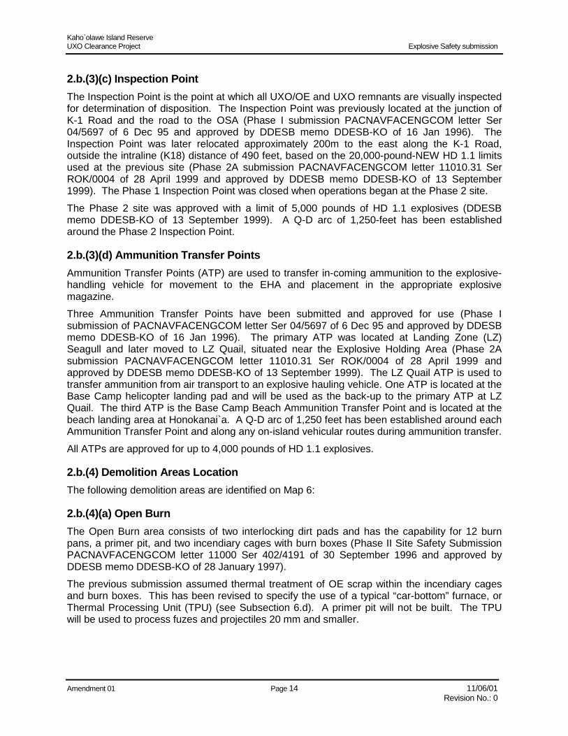
2.b.(3)(c) Inspection Point The Inspection Point is the point at which all UXO/OE and UXO remnants are visually inspected for determination of disposition. The Inspection Point was previously located at the junction of K-1 Road and the road to the OSA (Phase I submission PACNAVFACENGCOM letter Ser 04/5697 of 6 Dec 95 and approved by DDESB memo DDESB-KO of 16 Jan 1996). The Inspection Point was later relocated approximately 200m to the east along the K-1 Road, outside the intraline (K18) distance of 490 feet, based on the 20,000-pound-NEW HD 1.1 limits used at the previous site (Phase 2A submission PACNAVFACENGCOM letter 11010.31 Ser ROK/0004 of 28 April 1999 and approved by DDESB memo DDESB-KO of 13 September 1999). The Phase 1 Inspection Point was closed when operations began at the Phase 2 site. The Phase 2 site was approved with a limit of 5,000 pounds of HD 1.1 explosives (DDESB memo DDESB-KO of 13 September 1999). A Q-D arc of 1,250-feet has been established around the Phase 2 Inspection Point.
2.b.(3)(d) Ammunition Transfer Points Ammunition Transfer Points (ATP) are used to transfer in-coming ammunition to the explosive-handling vehicle for movement to the EHA and placement in the appropriate explosive magazine. Three Ammunition Transfer Points have been submitted and approved for use (Phase I submission of PACNAVFACENGCOM letter Ser 04/5697 of 6 Dec 95 and approved by DDESB memo DDESB-KO of 16 Jan 1996). The primary ATP was located at Landing Zone (LZ) Seagull and later moved to LZ Quail, situated near the Explosive Holding Area (Phase 2A submission PACNAVFACENGCOM letter 11010.31 Ser ROK/0004 of 28 April 1999 and approved by DDESB memo DDESB-KO of 13 September 1999). The LZ Quail ATP is used to transfer ammunition from air transport to an explosive hauling vehicle. One ATP is located at the Base Camp helicopter landing pad and will be used as the back-up to the primary ATP at LZ Quail. The third ATP is the Base Camp Beach Ammunition Transfer Point and is located at the beach landing area at Honokanai`a. A Q-D arc of 1,250 feet has been established around each Ammunition Transfer Point and along any on-island vehicular routes during ammunition transfer. All ATPs are approved for up to 4,000 pounds of HD 1.1 explosives.
2.b.(4) Demolition Areas Location The following demolition areas are identified on Map 6:
2.b.(4)(a) Open Burn The Open Burn area consists of two interlocking dirt pads and has the capability for 12 burn pans, a primer pit, and two incendiary cages with burn boxes (Phase II Site Safety Submission PACNAVFACENGCOM letter 11000 Ser 402/4191 of 30 September 1996 and approved by DDESB memo DDESB-KO of 28 January 1997). The previous submission assumed thermal treatment of OE scrap within the incendiary cages and burn boxes. This has been revised to specify the use of a typical “car-bottom” furnace, or Thermal Processing Unit (TPU) (see Subsection 6.d). A primer pit will not be built. The TPU will be used to process fuzes and projectiles 20 mm and smaller.

Kaho`olawe Island Reserve UXO Clearance Project Explosive Safety submission
Amendment 01 Page 15 11/06/01 Revision No.: 0
Map 6. Demolition Areas Location See oversized drawing “Map 6: Demolition Areas Location”
Or attached Autocad file: MAP 6 DEMOLITION AREAS.DWG

Kaho`olawe Island Reserve UXO Clearance Project Explosive Safety submission
Amendment 01 Page 16 11/06/01 Revision No.: 0
Two of the twelve previously sited burn pans will be built. The revised 7’-6”X8’ burn pans are manufactured from ½” steel and are 1’-6” deep. Each burn pan sits within a larger 8’X13’X2’ sand-filled, outer pan formed from the truck bed of an M-35A2 Cargo 2-1/2 Ton Truck. The outer pan provides spill protection for any spilled accelerant. No amendment to the site approval will be submitted for the minor changes to the burn pan construction. A Q-D arc of 1,250 feet is established and approved around the Open Burn Site per DDESB memo Ser. DDESB-KO of January 28, 1997. The Q-D arc is based upon and approved for up to 1,500 pounds of HD 1.1 munitions.
2.b.(4)(b) Open Detonation The Open Detonation area consists of six detonation pits (Phase II Site Safety Submission PACNAVFACENGCOM letter 11000 Ser 402/4191 of 30 September 1996 and approved by DDESB memo DDESB-KO of 28 January 1997). The number of pits has been reduced and only two of the six demolition pits will be built. Under the previous Phase II submission, the demolition pits were 6’X10’X6’ and had a tire barricade erected surrounding the pit. The tire barricade consisted of overlapping rows of tires, three deep. The revised demolition pits will be 2’X2’X2” and open, with no tire barricade. No amendment will be submitted to the site approval for the minor changes to the demolition pit construction. The Open Detonation area was sited using the MK 83 General Purpose bomb (1,000 pounds) for the fragmentation standoff distance and with a maximum of 1,000 pounds NEW per detonation (two MK 83s). The maximum calculated expected fragmentation standoff distance is 5,153 feet; however, testing indicates that with 6-15 feet of earth cover, based upon the amount of NEW being detonated, the fragmentation standoff distances may be dramatically reduced (e.g., 1,500 pounds NEW with 9-15 feet of earth cover with a 20% safety margin gives a fragmentation standoff distance of 2,800 feet). The initial site safety request for the Open Detonation range is for the 5,153 feet, for data being collected during the first three to five detonations and the results being reviewed, and for a proposed reduction in the fragmentation standoff distance. Mandatory evacuation distances for personnel not directly engaged in the demolition operation have been proven to vary according to the quantity and size of the munition, as specified in Paragraph 13-3.2.1, NAVSEA OP 5, Volume 1 Fifth Edition, and Paragraph E.4, Chapter 5, DoD 6055.9-STD and summarized in Table 13, Calculated Fragmentation Distances for Some Ordnance Found on Kaho`olawe, located in Section 8.
2.b.(4)(c) Thermal Processing Unit A Thermal Processing Unit (TPU) consisting of a typical “car-bottom” furnace will be used to thermally treat all non-explosive munitions and associated components. The TPU will burn the combustible constituents of the residual energetic that remained in and on the munitions. The TPU has not been sited and will be submitted in a separate site submission.
2.b.(5) Existing and Planned Uses “Title X of the FY 1994 Department of Defense Appropriations Act”, Section 10001(a) provides for the clearance and removal of unexploded ordnance and the environmental restoration of Kaho`olawe for the safe use of the island for appropriate cultural, historical, archaeological, and educational purposes as determined by the State of Hawaii. This is further clarified in the “Memorandum of Understanding between the United States Navy and the State of Hawaii
Kaho`olawe Island Reserve UXO Clearance Project Explosive Safety submission
Amendment 01 Page 17 11/06/01 Revision No.: 0
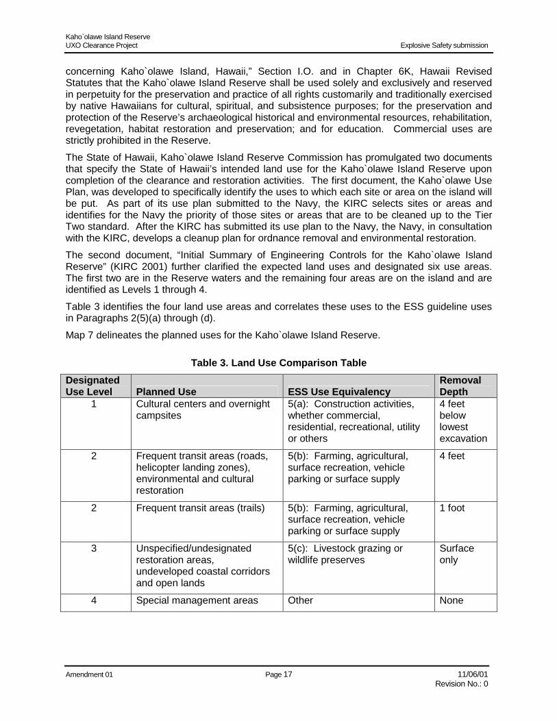
concerning Kaho`olawe Island, Hawaii,” Section I.O. and in Chapter 6K, Hawaii Revised Statutes that the Kaho`olawe Island Reserve shall be used solely and exclusively and reserved in perpetuity for the preservation and practice of all rights customarily and traditionally exercised by native Hawaiians for cultural, spiritual, and subsistence purposes; for the preservation and protection of the Reserve’s archaeological historical and environmental resources, rehabilitation, revegetation, habitat restoration and preservation; and for education. Commercial uses are strictly prohibited in the Reserve. The State of Hawaii, Kaho`olawe Island Reserve Commission has promulgated two documents that specify the State of Hawaii’s intended land use for the Kaho`olawe Island Reserve upon completion of the clearance and restoration activities. The first document, the Kaho`olawe Use Plan, was developed to specifically identify the uses to which each site or area on the island will be put. As part of its use plan submitted to the Navy, the KIRC selects sites or areas and identifies for the Navy the priority of those sites or areas that are to be cleaned up to the Tier Two standard. After the KIRC has submitted its use plan to the Navy, the Navy, in consultation with the KIRC, develops a cleanup plan for ordnance removal and environmental restoration. The second document, “Initial Summary of Engineering Controls for the Kaho`olawe Island Reserve” (KIRC 2001) further clarified the expected land uses and designated six use areas. The first two are in the Reserve waters and the remaining four areas are on the island and are identified as Levels 1 through 4. Table 3 identifies the four land use areas and correlates these uses to the ESS guideline uses in Paragraphs 2(5)(a) through (d). Map 7 delineates the planned uses for the Kaho`olawe Island Reserve.
Table 3. Land Use Comparison Table Designated Use Level Planned Use ESS Use Equivalency
Removal Depth
1 Cultural centers and overnight campsites
5(a): Construction activities, whether commercial, residential, recreational, utility or others
4 feet below lowest excavation
2 Frequent transit areas (roads, helicopter landing zones), environmental and cultural restoration
5(b): Farming, agricultural, surface recreation, vehicle parking or surface supply
4 feet
2 Frequent transit areas (trails) 5(b): Farming, agricultural, surface recreation, vehicle parking or surface supply
1 foot
3 Unspecified/undesignated restoration areas, undeveloped coastal corridors and open lands
5(c): Livestock grazing or wildlife preserves
Surface only
4 Special management areas Other None

Kaho`olawe Island Reserve UXO Clearance Project Explosive Safety submission
Amendment 01 Page 18 11/06/01 Revision No.: 0
Map 7. Proposed Land Use See oversized drawing “Map 7: Proposed Land Use”
Or attached Autocad file: PROPOSED LAND USE.DWG

Kaho`olawe Island Reserve UXO Clearance Project Explosive Safety submission
Amendment 01 Page 19 11/06/01 Revision No.: 0
2.c Quantity-Distance Maps The entire island, as well as the waters for two miles surrounding Kaho`olawe, are part of the Kaho`olawe Island Reserve and within the OE area of this project. All personnel on the island of Kaho`olawe are part of the clearance operation and therefore essential to the OE removal process. The public (those not supporting the clearance operation) does not have access to the island of Kaho`olawe without prior approval of the Navy and without EOD escorts. The following quantity-distance (Q-D) map(s) are provided:
2.c.(1) OE Areas to be cleared Q-D Map The entire island of Kaho`olawe is considered the OE area. There are currently no public accessible areas on Kaho`olawe. See Map 4 and Paragraph 2.b.(2), OE Removal Depth.
2.c.(2) Explosive Storage and Transfer Areas Q-D Map See Map 5 and Paragraph 2.b.(3), Explosive Storage and Transfer Facilities.
2.c.(3) Demolition Areas Q-D Map See Map 6 and Paragraph 2.b.(4), Demolition Areas Location.
2.d Soil Sampling Maps No explosive contaminated soil is expected to be found in this project. Verification of this expectation was completed by soil sampling during the development of the Model Project, and limited sampling to confirm this fact has been done as part of ongoing open detonation operations.

Kaho`olawe Island Reserve UXO Clearance Project Explosive Safety submission
Amendment 01 Page 20 11/06/01 Revision No.: 0
This page intentionally left blank

Kaho`olawe Island Reserve UXO Clearance Project Explosive Safety submission
Amendment 01 Page 21 11/06/01 Revision No.: 0
Section 3 Amount and Type of OE This section provides the expected amount(s) and type(s) of OE based upon historical research or data generated from surface or intrusive sampling.
3.a Site Investigation NAVEODTD personnel supported by personnel from the U.S. Army Defense Ammunition Center and Comarco Systems, Inc. conducted preliminary UXO assessments of target locations (May 1995) and the shoreline (April and May 1996), followed by an extensive site investigation of the island during February and March 1997. The data collected as part of the site investigation were analyzed with the preliminary assessment and all documentation found during archival research of clearance reports, target maps, ammunition issues, and various studies and papers written in support of UXO clearance of the Island. This information is documented in the Kaho`olawe Site Characterization Report (NAVEODTD 1998). Table 4 lists the types of ordnance within each of the above categories commonly found on Kaho`olawe Island. The clearance items are predominately UXO, UXO-related remnants, and target materials. There are no reports which indicate that radioactive materials or nuclear, biological, and chemical warfare materials were used on Kaho`olawe.
Table 4. Ordnance Commonly Found on Kaho`olawe Island
Name Explosive Weight (lb) Type Fuzing Bombs 2000 lb SAP Bomb 1,000 Impact
Impact Cocked Striker Impact Delay
2000 lb LDGP Bomb/MK84 1,000 Impact Impact Cocked Striker Impact Delay VT
1000 lb LDGP Bomb/MK 83 500 Impact Impact Cocked Striker Impact Delay VT
500 lb LDGP Bomb/MK 82 200 Impact Impact Cocked Striker Impact Delay VT
250 lb LDGP Bomb/MK 81 100 Impact Impact Cocked Striker Impact Delay VT
FAE Bombs 75 E.O. Mech Time Piezoelectric
40 lb Frag Bombs 23 Impact
Fire Bombs 705 All-Ways Acting Napalm (WP Igniters)

Kaho`olawe Island Reserve UXO Clearance Project Explosive Safety submission
Amendment 01 Page 22 11/06/01 Revision No.: 0
Table 4. Ordnance Commonly Found on Kaho`olawe Island (Continued) Name Explosive Weight (lb) Type Fuzing
Projectiles 20-mm Projectiles 0.02 Impact
Impact Self Destruct Impact (Cocked Striker)
3”/50 Projectiles 1.66 Impact Mech Time VT
5”/38 Projectiles 8 Impact Impact (Cocked Striker) (Tail and Nose)
5”/54 Projectiles 10 Impact Mech Time
106-mm Projectile (HEAT) 2.79 Impact PIBD Piezoelectric
105-mm Projectile 7.76 Piezoelectric Impact Mech Time
8” Projectiles 21.58 Impact Mech Time
16” Projectile 153 Impact
Mortars 81-mm Mortar 4.3 Impact
Mech Time Powder Time
60-mm Mortar 5 Impact
60-mm Mortar 1 WP Mech Time Powder Time
Grenades 40-mm Grenade .17 All-Ways Acting
Rockets 2.75” Rocket 2.3 Impact
VT 66-mm LAW 1.5 Impact
3.5” Bazooka 3 Impact
5” HVAR Rocket 20 Impact VT
5” Zuni Rocket 20 Impact VT
4.5” Barrage Rocket 8 Mech Time Powder Time
4.2” Rocket Thrown Depth Charge 15 All-ways acting Hydrostatic

Kaho`olawe Island Reserve UXO Clearance Project Explosive Safety submission
Amendment 01 Page 23 11/06/01 Revision No.: 0
Table 4. Ordnance Commonly Found on Kaho`olawe Island (Continued) Name Explosive Weight (lb) Type Fuzing
7.2” Rocket Thrown Depth Charge 33 All-ways acting Hydrostatic
Guided Missiles Tow Surface Attack 10 Impact
Dragon Anti-Tank 6 Impact
AGM-12 Bullpup 250 Impact VT
AGM-45 Shrike 55 Impact VT
Pyrotechnics MK 24 Aircraft Illuminating Flare 17 Mech Time
Powder Time
MK 45 Aircraft Illuminating Flare 17 Powder Time
5 Inch Projectile (Illuminating) 6 Powder Time Mech Time
Small Arms .22 Caliber .9-mm .45 Caliber 5.56-mm 7.62-mm 12 Gauge Shotgun Shell 50 Caliber
Varied Not Applicable
Submunitions Butterfly Bomblets 0.5 Impact
Anti Disturbance Long Delay
Baseball Type Bomblets (Anti-Personnel)
0.25 Anti-Disturbance
3.b Most Probable Munition The DDESB (DDESB memo SER. DDESB-KO of 27 February 1998) promulgated most Probable Munition (MPM) guidance in 1998: “For Q-D purposes, a most probable munition must be established for each OE area. The most probable munition is the round with the greatest fragment distance that can reasonably be expected to exist in any particular OE area.” Instead, a Most Hazardous/Probable Munition for Q-D purposes was established that pre-dates the MPM guidance of DDESB in 1998. The Most Hazardous/Probable Munition is the most sensitive or hazardous munition type to be commonly expected during the course of the cleanup. Based upon the records of previous clearance activities and site assessments, the Most Hazardous/Probable Munition for Kaho`olawe is the 40 mm projectile.
Kaho`olawe Island Reserve UXO Clearance Project Explosive Safety submission
Amendment 01 Page 24 11/06/01 Revision No.: 0
3.c Explosive Contaminated Soil No explosive contaminated soil is expected to be found on Kaho`olawe.
3.d Explosive Contaminated Buildings No explosive contaminated buildings are expected to be found on Kaho`olawe.

Kaho`olawe Island Reserve UXO Clearance Project Explosive Safety submission
Amendment 01 Page 25 11/06/01 Revision No.: 0
Section 4 Start Date
4.a Project History In 1976, the members of the Protect Kaho`olawe `Ohana (PKO) filed suit in Federal District Court, Aluli et al. v. Brown (civil suit no. 76-0380), seeking to enjoin the Navy’s bombing activities on Kaho`olawe. In 1977, the Federal District Court ordered a partial summary judgment in favor of the Aluli et al., and the Navy was required to conduct an environmental impact statement and supply an inventory of, and protect, the historic sites on the island. In 1980, a settlement Consent Decree and Order was reached in the Aluli et al. v. Brown civil suit. Under the Consent Decree and Order, the Navy agreed to survey and protect historic and cultural sites on the island, clear surface ordnance from 10,000 acres, continue soil conservation and revegetation programs, eradicate the goats from the island, limit ordnance impact training to the central third of the island, and allow monthly PKO accesses to the island. Through those monthly accesses, the PKO has regularly visited the island for religious and cultural purposes, as well as revegetation and conservation programs. On March 18, 1981, the entire island was listed on the National Register for Historical Places and designated the Kaho`olawe Archaeological District. The Kaho`olawe Archaeological District contains 544 recorded archaeological/historical sites and over 2,000 features, as well as previously unrecorded features associated with traditional and historic Hawaiian land use, ranching, and military activities. In 1990, President George Bush issued a Memorandum to Secretary of Defense, Richard Cheney, which directed the Secretary to discontinue use of Kaho`olawe as a weapons range effective immediately. Section 8118 of Public Law 101-511, enacted by Congress in 1990, established the Kaho`olawe Island Conveyance Commission to recommend terms and conditions for the conveyance of Kaho`olawe from Federal jurisdiction to the State of Hawaii. The law prohibited the use of the island for weapons delivery training until after the final Kaho`olawe Island Conveyance Commission report was delivered to Congress. The Commission submitted its final report with findings and recommendations to Congress in March 1993 and dissolved six months later in September 1993. During the same period, the Navy in consultation with the State Historic Preservation Office, the Protect Kaho`olawe `Ohana, and the County of Maui met and developed a Cultural Resources Management Plan for the Kaho`olawe Archaeological District. That document was finalized in January 1995 (Ogden Environmental, 1995). In 1993, Senator Daniel K. Inouye of Hawaii sponsored Title X of the Fiscal Year 1994 Department of Defense Appropriation Act (PL 103-139, 107 Stat. 1418. 1479-1484). Title X authorized conveyance of Kaho`olawe and its surrounding waters to the State of Hawaii. It also provided for the “clearance or removal of unexploded ordnance” and environmental restoration of the island to offer “meaningful safe use of the island for appropriate cultural, historical, archaeological, and educational purposes, as determined by the State of Hawaii.” Hawaii Revised Statutes, Chapter 6K, created the Kaho`olawe Island Reserve Commission (KIRC) to have policy and management oversight of the Kaho`olawe Island Reserve. The statute requires that the island (including waters extending seaward two nautical miles from the shoreline) be used solely and exclusively for the following purposes:

Kaho`olawe Island Reserve UXO Clearance Project Explosive Safety submission
Amendment 01 Page 26 11/06/01 Revision No.: 0
1) Preservation and practice of all rights customarily and traditionally exercised by the native Hawaiians for cultural, spiritual, and subsistence purposes
2) Preservation and protection of its archaeological, historical, and environmental resources 3) Rehabilitation, revegetation, habitat restoration, and preservation 4) Education Additionally, the island is to be preserved in perpetuity for the above uses. Commercial uses are strictly prohibited. As directed by Title X, a Memorandum of Understanding (MOU) between the Navy and the State of Hawaii was prepared to govern the conveyance of the island to the State of Hawaii with six specific agreements (regulatory framework; site protection; public participation; security; emergency communication; and regular interval clearance and removal of newly discovered, previously undetected ordnance). The Navy and the Governor of the State of Hawaii executed the MOU on May 6, 1994. Pursuant to Title X and the MOU, title to the island of Kaho`olawe was transferred to the State of Hawaii on May 9, 1994. Under the MOU, the Navy retains access control to the island until clearance and environmental restoration activities are completed or November 11, 2003, whichever comes first. The State, through the KIRC, is the primary stakeholder and landowner, responsible for the long term restoration and management of Kaho`olawe for appropriate cultural, historical, archaeological, and education purposes. The State holds statutory, regulatory, and enforcement interest in the protection of public health and the environment. The MOU further provides in Section VIII.C(5)(b) that "The access to Kaho`olawe that was afforded under the 1980 Consent Decree, described at Section I.C., remains in effect so long as that Consent Decree remains in effect." The regulatory process set forth in the MOU maintains that the Navy shall proceed with the cleanup in consultation with the KIRC and in a manner consistent with the National Oil and Hazardous Substances Pollution Contingency Plan, 40 CFR Section 300 et seq. On December 13, 1996, the Naval Facilities, Engineering Command, Pacific Division, solicited a Request for Proposals entitled, Cost-Plus-Award-Fee Contract for the Unexploded Ordnance Clearance Project, Kaho`olawe Island Reserve, Hawaii (Solicitation No. N62742-95-R-1369).to conduct unexploded ordnance clearance and environmental restoration of Kaho`olawe Island (Clearance Contract). The Clearance Contract was awarded to the Parsons-UXB Joint Venture (PUXB) on July 29, 1997.
4.b Project Duration Actual OE clearance activities began on-site December 7, 1997, continues to the present, and is expected to end November 2003.
Kaho`olawe Island Reserve UXO Clearance Project Explosive Safety submission
Amendment 01 Page 27 11/06/01 Revision No.: 0
Section 5 Frostline No frostline exist at this OE site, but heavy erosion in the OE areas have created erosion pathways for OE to migrate. OE located below the removal depth may be exposed over time, due to erosion. Currently, long-term monitoring has not been developed. The State of Hawaii and the Navy are in the process of developing a long-term monitoring agreement.

Kaho`olawe Island Reserve UXO Clearance Project Explosive Safety submission
Amendment 01 Page 28 11/06/01 Revision No.: 0
This page intentionally left blank

Kaho`olawe Island Reserve UXO Clearance Project Explosive Safety submission
Amendment 01 Page 29 11/06/01 Revision No.: 0
Section 6 Clearance Techniques
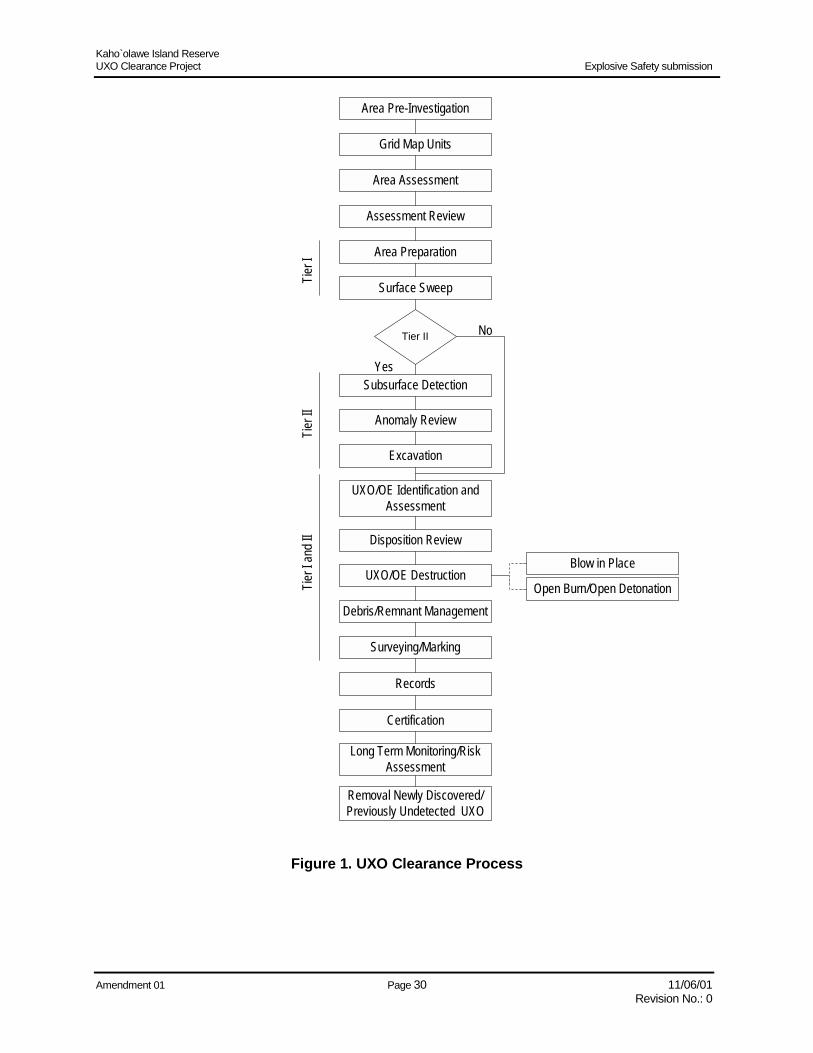
6.a UXO Detection and Clearance Methods The UXO detection and clearance methods consist of two separate, but linked, processes. The first is the Tier I (surface) clearance process and the second is the Tier II (subsurface) clearance process. Tier I technical requirements include pre-investigation archival searches; establishment of work area boundaries and sub-areas (grid map units); completion of a UXO/OE concentration assessment; historic property survey and environmental conditions report; historic preservation, environmental, and natural resources monitoring (as required); sweep area preparation; clearance of all UXO, UXO-related remnants, target materials, and other non-UXO-related materials from the surface of the designated work areas; debris/remnant management; UXO disposition; quality control; and data management. Tier II technical requirements include subsurface detection, excavations, debris/remnant management, UXO destruction, quality control, data management, and documentation of the detection process, remediation depth to which UXO are removed, and exceptions. The technical steps of the UXO clearance process are identified in Figure 1. This process incorporates the various regulatory, technical, and contractual requirements into a single integrated work process. Each step will be accomplished in strict accordance with the approved Work Plan and Standard Operating Procedures. All personnel are required to implement the Standard Operating Procedures as assigned.
The following is summary of the applicable UXO clearance subtasks as shown in Figure 1:
6.a.(1) Area Pre-investigation The Area Pre-Investigation is a review of all existing data relating to a specific work area. UXO, historic preservation, environmental, natural resources, and survey personnel will review existing documentation as it relates to their functional areas of expertise. The Area Pre-Investigation team will review existing maps, reports, and data from previous studies in order to formulate predictions of on-site conditions. The information will be analyzed and the team will summarize its findings and ultimately develop an Area Pre-Investigation map of each work area. The map will note anticipated work area conditions (including UXO, historic properties, environmental, and natural resources), demarcate the work area boundaries and entry/exit routes, and identify the mode of transportation required to enter/exit the work area.
6.a.(2) Grid Map Units The work areas are subdivided into grid map units that measure one hectare (100 meters x 100 meters). The grid map units enhance command and control of the work area and enable Range Control to more closely monitor the location of personnel and types of operations within a given work area. Clearance boundaries and boundaries between various levels of UXO clearance levels will also be delineated.
Kaho`olawe Island Reserve UXO Clearance Project Explosive Safety submission
Amendment 01 Page 30 11/06/01 Revision No.: 0
Area Pre-Investigation
Area Assessment
Area Preparation
Surface Sweep
Tier II
Subsurface Detection
Excavation
UXO/OE Destruction
Debris/Remnant Management
Surveying/Marking
Certification
Records
Tier I
Tier I
ITie
r I an
d II
No
Yes
Grid Map Units
Blow in Place
Open Burn/Open Detonation
Removal Newly Discovered/Previously Undetected UXO
UXO/OE Identification andAssessment
Assessment Review
Anomaly Review
Disposition Review
Long Term Monitoring/RiskAssessment
Figure 1. UXO Clearance Process
Kaho`olawe Island Reserve UXO Clearance Project Explosive Safety submission
Amendment 01 Page 31 11/06/01 Revision No.: 0
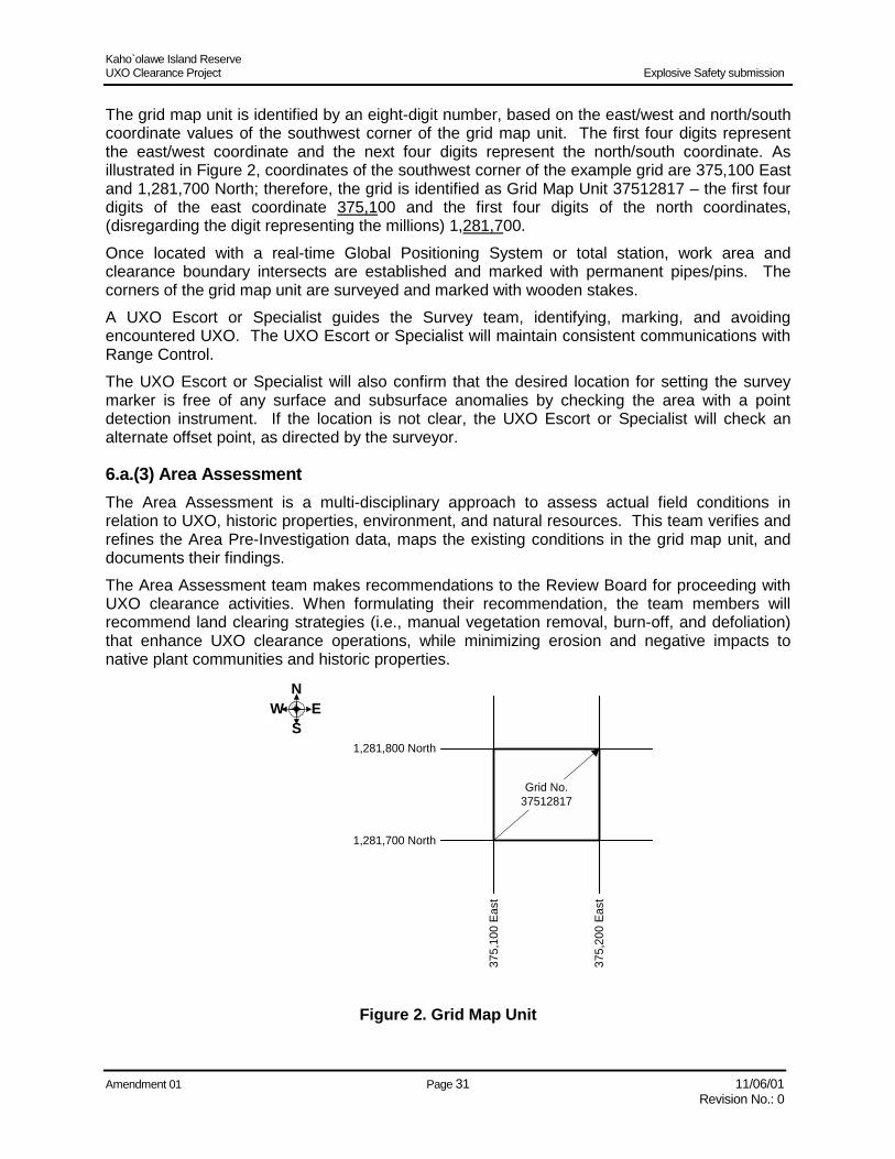
The grid map unit is identified by an eight-digit number, based on the east/west and north/south coordinate values of the southwest corner of the grid map unit. The first four digits represent the east/west coordinate and the next four digits represent the north/south coordinate. As illustrated in Figure 2, coordinates of the southwest corner of the example grid are 375,100 East and 1,281,700 North; therefore, the grid is identified as Grid Map Unit 37512817 – the first four digits of the east coordinate 375,100 and the first four digits of the north coordinates, (disregarding the digit representing the millions) 1,281,700. Once located with a real-time Global Positioning System or total station, work area and clearance boundary intersects are established and marked with permanent pipes/pins. The corners of the grid map unit are surveyed and marked with wooden stakes. A UXO Escort or Specialist guides the Survey team, identifying, marking, and avoiding encountered UXO. The UXO Escort or Specialist will maintain consistent communications with Range Control. The UXO Escort or Specialist will also confirm that the desired location for setting the survey marker is free of any surface and subsurface anomalies by checking the area with a point detection instrument. If the location is not clear, the UXO Escort or Specialist will check an alternate offset point, as directed by the surveyor.
6.a.(3) Area Assessment The Area Assessment is a multi-disciplinary approach to assess actual field conditions in relation to UXO, historic properties, environment, and natural resources. This team verifies and refines the Area Pre-Investigation data, maps the existing conditions in the grid map unit, and documents their findings. The Area Assessment team makes recommendations to the Review Board for proceeding with UXO clearance activities. When formulating their recommendation, the team members will recommend land clearing strategies (i.e., manual vegetation removal, burn-off, and defoliation) that enhance UXO clearance operations, while minimizing erosion and negative impacts to native plant communities and historic properties.
375,
200
East
Grid No.37512817
N
SEW
1,281,700 North
375,
100
East
1,281,800 North
Figure 2. Grid Map Unit

Kaho`olawe Island Reserve UXO Clearance Project Explosive Safety submission
Amendment 01 Page 32 11/06/01 Revision No.: 0
The acquired data will be electronically maintained in PUXB’s Data Management System and uploaded to Electronic Grid Folders and the Kaho`olawe Island Geographic Information System (KIGIS) for future review and reporting purposes. UXO personnel will guide the Area Assessment team through the grid map unit. From a UXO perspective, they will:
• = Visually scan the terrain to identify surface UXO/OE, craters, and other potential explosive hazards
• = Verify and record the types and density of UXO, UXO-related remnants, target materials, and non-UXO-related materials in the grid map unit
• = Identify and mark UXO to avoid UXO hazards
• = Identify anomaly-free areas for the placement of markers The findings will be documented on a UXO Area Assessment form and incorporated into PUXB’s Data Management System. This information will be used to schedule and sequence future UXO clearance operations. A surveyor utilizes Global Positioning System instrumentation to verify the position of grid map unit corners, historic properties and environmental natural resources significant areas; and topography and planimetric features. A Total Station survey instrument will be used when the vegetation cover prevents the use of the Global Positioning System. The surveyor will:
• = Record the position of all grid corners, compare the field positions to the proposed positions, and report any differences noted
• = Record the position of all clearance boundary points
• = Record the position of marked surface UXO
• = Record the topography and planimetric features of the grid
• = Record the outlines of eroded areas (as identified by natural resources personnel) The recorded field data will be reduced and downloaded into the KIGIS, which will produce a plot on the grid map unit. A grid map unit map, with one-meter contours, will be produced and utilized to implement all future clearance activities.
6.a.(4) Assessment Review The findings and recommendations of the Area Assessment functional areas (UXO, historic preservation, natural resources, environmental, and survey) will be evaluated and compared to predicted (or available) information bases. This information is reviewed by PUXB’s members of the Review Board. If the assessment data is quite different from the expected, a new risk assessment for that area may be generated.
6.a.(5) Area Preparation Area Preparation activities include reduction of vegetation that limits the effectiveness of surface and subsurface clearance personnel and/or equipment and allows for safer, more effective UXO clearance operations. These activities (manual removal, controlled burn, or defoliation) are dictated by a grid map unit’s terrain and concentration of vegetation, historic properties, and environmental and natural resources. Area preparation activities will follow UXO avoidance procedures.

Kaho`olawe Island Reserve UXO Clearance Project Explosive Safety submission
Amendment 01 Page 33 11/06/01 Revision No.: 0
6.a.(6) Tier I (Surface) UXO Clearance Operations Surface Sweep (Tier I) clearance requirements are defined as “removal or clearance of all unexploded ordnance from the surface of the island.” Surface Sweeps are conducted by visual and/or detector-aided operations, with zero (0) foot subsurface investigation. Detector-aided operations will be used when visibility is restricted. The UXO team members will:
• = Inspect surface materials and segregate them as UXO-related remnants, target materials, or non-UXO-related materials.
• = Flag, make a preliminary identification, and record previously unidentified UXO by grid map unit. Each item will be given a unique identifier number for monitoring purposes and chain-of-custody for each item will commence at this time.
6.a.(6)(a) Surface Sweep Specifications Minimum UXO Tier I Clearance Criteria is defined in Table 5, Minimum Tier I Clearance Criteria. These requirements are based upon actual UXO recorded on Kaho`olawe and developed from the Kaho`olawe Site Characterization Report (NAVEODTD 1998). Minimum UXO detection requirements for Tier I clearance are an 85% probability of detection with a 90% confidence level. Tier I clearance includes removal of surface debris. Specific clearance areas and requirements for Tier I clearance will be delineated in individual Task Orders and may include only UXO or UXO remnants (e.g., those areas where the task may be specifically for reduction of the UXO hazard severity level).
6.a.(6)(b) Surface Sweep Procedures A UXO Surface Sweep Team is an eight-man team consisting of a UXO Specialist Supervisor (UXOSS) and seven UXO Sweep Personnel (UXOSP). The UXOSS positions his sweep team abreast at approximately one-meter intervals. Spacing and alignment may be adjusted by the UXOSS, based upon actual field terrain, vegetation, and UXO items expected.
Table 5. Minimum Tier I Clearance Criteria
UXO Minimum Size
(English) UXO* All
UXO Remnants 1” x 2” or larger
Small Arms 0.22” Diameter to 50 Caliber
40-mm Grenades 1.6” Diameter
M26 Submunitions M38 Submunitions And Similar Items**
2.75” Diameter 1.75” Diameter
*UXO includes all items that contain explosives, such as: Fuzes, Bulk Explosives, Pyrotechnics, and Propellant **Nonferrous Items
Kaho`olawe Island Reserve UXO Clearance Project Explosive Safety submission
Amendment 01 Page 34 11/06/01 Revision No.: 0
The sweep team systematically conducts a visual and/or detector-aided surface sweep of their assigned GMU. UXOSP will pickup all expended small arms (0.50 caliber or smaller), UXO-related remnants, target material, and non-UXO-related materials. All metal pieces larger than one inch by two inches are removed from the surface. The UXOSS will pick up and bag all unfired small arms, 20-mm projectiles, raw explosives, and propellant. This material is consolidated, tagged, and moved to an in-grid collection point (see Paragraph 8.d.(2), Collection Points). All UXO/OE larger than 20 mm or small submunitions are flagged and documented for later recovery or disposal by a Demolition Team.
6.a.(7) Tier II (Subsurface) UXO Clearance Operations Subsurface detection is conducted utilizing a variety of geophysical detection equipment (see Paragraph 6.b.(1), Detector Selection). During these operations, subsurface anomalies that resemble UXO/OE will be identified, and the location of the subsurface anomalies will be marked with a flag. Geophysical Detection Personnel will locate and mark subsurface target anomalies resembling UXO. This systematic process will be conducted with a geophysical detection instrument that provides visual and audible signals to the operator. The operator will mark all anomalies with a flag and will record the visual readings and approximate position coordinates within the grid map unit. The recorded information will be entered into PUXB’s Data Management System. Once a Review Board Decision is formulated by the Review Board, this information will be used to re-acquire the anomalies for subsequent operations.
6.a.(7)(a) Subsurface Detection Specifications Tier II UXO clearance requirements are defined in Table 6, UXO Detection Requirements for Tier II Clearance. These requirements are based upon actual UXO penetration depths experienced on Kaho`olawe and developed from the Kaho`olawe Site Characterization Report (NAVEODTD 1998). Minimum UXO detection statistics required for Tier II clearance are an 85% probability of detection with a 90% confidence level. Tier II clearance includes removal of metallic debris. Specific clearance areas and depth requirements are specified in individual task orders.
6.a.(7)(b) Subsurface Detection Procedures A Geophysical Detection Team is comprised of a Geophysics Assistant (GA) and a Geophysics Detector Personnel. The geophysical detection team selects one of the geophysical detectors listed in Paragraph 6.b.(1), Detector Selection, depending upon the terrain, field conditions, and clearance objectives to perform a systematic geophysical search for subsurface anomalies. Geophysical detection is conducted using either of the two following methods.
6.a.(7)(b)(1) Field Discrimination The Geophysical Detection Team, utilizing both the audio tone and deflection meter reading of the geophysical detector, systematically sweep one-meter lanes of their assigned grid. Sweeps are conducted either north-south or east-west, depending upon the terrain and field conditions. A threshold value of 5 mV above background is set as the criteria for anomaly selection. Anomalies are marked in the field, detector information is recorded, and the position is located. Relevant information is documented and passed to an Excavation Team to uncover and identify potential UXO/OE items.

Kaho`olawe Island Reserve UXO Clearance Project Explosive Safety submission
Amendment 01 Page 35 11/06/01 Revision No.: 0
Table 6. UXO Detection Requirements for Tier II Clearance
Item Depth
(English) Depth
(Metric) 20 mm w/Casing 6” 15.2 cm
60 mm – 81 mm Mortar 14” 35.6 cm
2.25 – 2.75” Rocket Warhead 30” 76.2 cm
3” Projectile 23” 58.4 cm
5” Projectile 36” 91.4 cm
100 lb A/N Bomb 48” 1.2 m
250 lb A/N Bomb 48” 1.2 m
250 lb MK Bomb 72” 1.8 m
500 lb A/N Bomb 48” 1.2 m
500 lb MK Bomb 96” 2.4 m
1000 lb A/N Bomb 96” 2.4 m
1000 lb MK Bomb 96” 2.4 m
2000 lb MK Bomb 120” 3.0 m
6.a.(7)(b)(2) Digital Data Collection In the digital data collection mode, the Geophysical Detector Team uses an integrated GPS geophysical detector to collect geophysical data over one-meter sweep lanes. The Geophysical Detection Team systematically sweeps each lane within the search grid and electronically collects geophysical and GPS information. The geophysical data files are downloaded and merged with processed GPS files. The merged files are then converted into a three-plane coordinate system for importing into Geosoft’s UX-Detect software. Using the Geosoft software, locations of anomalies are determined by applying peak detection techniques. Anomaly lists are generated and used by the Excavation team to uncover and identify potential UXO/OE items.
6.a.(8) Anomaly Review Once consolidated, the findings and recommendations that result from Subsurface Detection operations will be submitted to the Anomaly Review Board. Information developed or discovered that is significantly different from that expected from historic review may result in changes to the Kaho`olawe Use Plan or clearance requirements, as agreed to by the Navy and KIRC. If anomalies are detected at depths greater than those specified in the UXO Clearance Tier Chart (Table 2) or if anomalies fall within culturally and/or archaeologically-sensitive areas where excavation cannot be accomplished, the Review Board will also review these anomalies again and formulate a Review Board Decision for further actions related to these specific anomalies.
6.a.(9) Excavation Excavation operations are conducted to investigate and identify subsurface target anomalies to the depth requirement.

Kaho`olawe Island Reserve UXO Clearance Project Explosive Safety submission
Amendment 01 Page 36 11/06/01 Revision No.: 0
UXO personnel will manually excavate target anomalies to a depth of one-foot (i.e., with a pick and shovel). If an anomaly is deeper than one-foot, it will be either mechanically excavated (i.e., backhoe) or manually excavated when site constraints and accessibility do not permit mechanical excavation.
6.a.(10) UXO/OE Identification and Assessment All UXO/OE will be appropriately identified and assessed prior to disposition. After each UXO/OE item is positively identified, an appropriate destruction action will be determined. Representatives of the UXO, historic preservation, environmental, and natural resources functional areas will determine the hazards associated with the item and the potential adverse impacts a demolition will have on the surrounding area. This team will recommend one of the following means of disposition to the Review Board:
• = Blow In Place
• = Consolidate to a Centralized Facility
• = No Action Initially, UXO personnel will make a preliminary identification of all encountered UXO. At this level of identification, items will be categorized as:
• = Bombs
• = Projectiles
• = Mortars
• = Grenades
• = Rockets
• = Guided Missiles
• = Pyrotechnics
• = Small Arms
• = Submunitions
• = Ordnance/Explosives Components
Once the UXO personnel gain complete access to the UXO/OE item, they can analyze the physical evidence of the item (paint markings, other markings, measurements, etc.) and research technical publications to positively identify the item and its fuzing. In certain cases, an encountered UXO/OE item will be unsafe to move. UXO/OE items that are unsafe to move must be detonated in place (blown in place or BIP’d). UXO personnel will determine the best approach to the demolition and calculate the resultant fragmentation distance. Safe-to-move items will be relocated and consolidated at the Open Storage Area (OSA) for disposition at a centralized facility (Open Burn/Open Detonation or thermal treatment).
6.b Method of Detection The metal and geophysical detectors that are used are shown in Table 7.
Table 7. Detector Selection Tier I (Surface) UXO Clearance Tier II (Subsurface) UXO Clearance • = White XLT� Spectrum All-Metals Detector • = Geonics Time Domain Electromagnetic
Induction Magnetometer (TDEM) EM-61
• = Geophysics Technology Limited (GTL) TM-5emu Digital Metal Detector
Kaho`olawe Island Reserve UXO Clearance Project Explosive Safety submission
Amendment 01 Page 37 11/06/01 Revision No.: 0
6.b.(1) Detector Selection Surface Sweep utilizes the White XLT� Spectrum All-Metals Detector as an electronic aid to a visual UXO search. Subsurface detection utilizes the Geonics Time Domain Electromagnetic Induction Magnetometer (TDEM) EM-61 in two modes.
• = Field Discrimination (audio mode) –Geophysical operators utilize the EM-61 as a “mag and flag” detector, immediately locating anomalies in the field. See Paragraph 6.b.(3)(a), Geophysical Limitations. This is the primary method of operation for subsurface detection.
• = Digital Recording (post-processing mode) – Geophysical operators use EM-61 data collected in record mode for analysis and select anomalies that could potentially represent buried ordnance. Anomalies are selected using Geosoft’s UX-Detect EM-61 software application. Location information is collected using an on-board, integrated Global Positioning System (GPS). This method is used primarily for quality control inspections.
The Geophysics Technology Limited (GTL) TM-5emu Digital Metal Detector is used primarily in the field discrimination mode and used as a “mag and flag” detector. See Subparagraph 6.b.(3)(a), Geophysical Limitations.
6.b.(1)(a) Selection Criteria The UXO clearance process requires selection of subsurface detection and removal approaches and methodologies that will accomplish the end objective – reasonable safe use of each identified area of the island for the planned land use specified in the Kaho`olawe Use Plan (PBR Hawaii 1995). The selected subsurface detection system(s) must provide operational personnel the capability to safely and precisely locate UXO, regardless of whether the UXO are lying on the surface, covered with heavy overgrowth, buried deeply in the soil, or located underwater and potentially buried in the sediments. Detection and location of UXO primarily depends on the ability to distinguish their physical characteristics from those of the surrounding environment. Factors that affect UXO detection include:
• = Munition size
• = Shape
• = Casing material
• = Fuzing
• = Depth and orientation
• = Soil composition and geology
• = Vegetation and terrain
• = Background interference from metal scrap
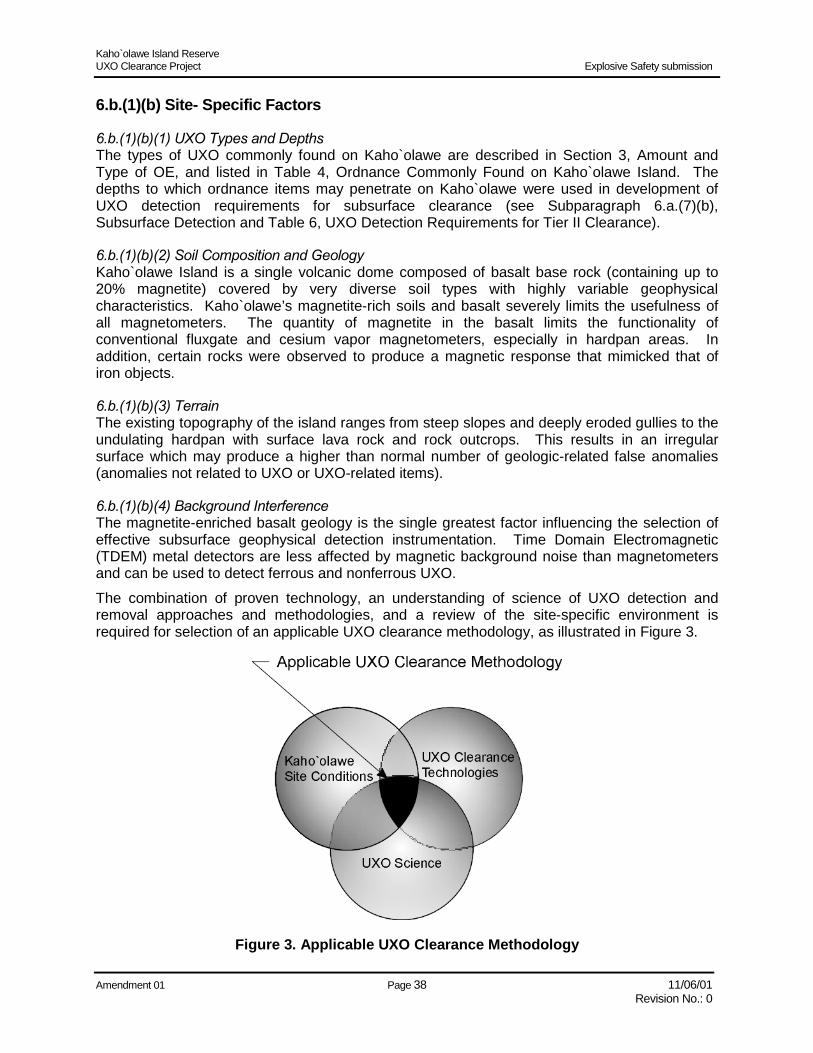
Kaho`olawe Island Reserve UXO Clearance Project Explosive Safety submission
Amendment 01 Page 38 11/06/01 Revision No.: 0
6.b.(1)(b) Site- Specific Factors
6.b.(1)(b)(1) UXO Types and Depths The types of UXO commonly found on Kaho`olawe are described in Section 3, Amount and Type of OE, and listed in Table 4, Ordnance Commonly Found on Kaho`olawe Island. The depths to which ordnance items may penetrate on Kaho`olawe were used in development of UXO detection requirements for subsurface clearance (see Subparagraph 6.a.(7)(b), Subsurface Detection and Table 6, UXO Detection Requirements for Tier II Clearance).
6.b.(1)(b)(2) Soil Composition and Geology Kaho`olawe Island is a single volcanic dome composed of basalt base rock (containing up to 20% magnetite) covered by very diverse soil types with highly variable geophysical characteristics. Kaho`olawe’s magnetite-rich soils and basalt severely limits the usefulness of all magnetometers. The quantity of magnetite in the basalt limits the functionality of conventional fluxgate and cesium vapor magnetometers, especially in hardpan areas. In addition, certain rocks were observed to produce a magnetic response that mimicked that of iron objects.
6.b.(1)(b)(3) Terrain The existing topography of the island ranges from steep slopes and deeply eroded gullies to the undulating hardpan with surface lava rock and rock outcrops. This results in an irregular surface which may produce a higher than normal number of geologic-related false anomalies (anomalies not related to UXO or UXO-related items).
6.b.(1)(b)(4) Background Interference The magnetite-enriched basalt geology is the single greatest factor influencing the selection of effective subsurface geophysical detection instrumentation. Time Domain Electromagnetic (TDEM) metal detectors are less affected by magnetic background noise than magnetometers and can be used to detect ferrous and nonferrous UXO. The combination of proven technology, an understanding of science of UXO detection and removal approaches and methodologies, and a review of the site-specific environment is required for selection of an applicable UXO clearance methodology, as illustrated in Figure 3.
Figure 3. Applicable UXO Clearance Methodology

Kaho`olawe Island Reserve UXO Clearance Project Explosive Safety submission
Amendment 01 Page 39 11/06/01 Revision No.: 0
A single detection system that can accomplish UXO detection unambiguously within all the above variables is non-existent. The three major categories of technologies for the detection of UXO are magnetometry, infrared (IR), and ground penetrating radar (GPR). Magnetometers (fluxgate or cesium vapor) are the most commonly used form of detecting UXO on or below the surface and can be used for underwater use. Magnetometers can only detect UXO containing ferrous metal. Metal detectors can locate both ferrous and nonferrous metallic objects and can be adapted for use underwater; however, conventional metal detectors can only detect UXO located on or very near the surface. TDEM induction metal detectors have proven to be reliable in detecting ferrous and nonferrous UXO. Infrared has proven effective only in conducting gross assessments of areas containing UXO, but lacks the capability to provide point detection of UXO. GPR can collect rough images of buried metallic and nonmetallic UXO. GPR effectiveness is severely limited in certain soil conditions. Technology performance results from advanced technology demonstrations (ATDs) have shown detection systems exhibiting UXO detection capabilities ranging from 0 to 85%. For example, if 100 UXO items are located within a work area scheduled for a Tier II removal action, a detection system with an 85% detection capability may detect 85 of the 100 UXO items. The results of the ATDs also show a marginal ability for the detection systems demonstrated to discriminate between UXO/UXO-related items and non-UXO-related anomalies. This resulted in high false alarm rates translating into many empty holes and unnecessary excavations. A 70% false alarm rates results in the excavation of 100 holes to unearth 30 UXO/UXO-related items. During the Model Project, performance results of three (3) detection system configurations showed that the ability to discriminate between UXO and/or UXO-related remnants and non-UXO-related anomalies scored 25, 65, and 87%, respectively, with false alarm rates of 75, 35, and 13%, respectively. Based upon these results the TDEM EM61 field discrimination detection system was selected as the primary clearance detector. The data collection and post processing and analysis process for the TDEM EM61, even though it had a higher false positive rate, was also selected for use in dense target areas, as it tended to allow the operator to better discriminate between close targets.
6.b.(1)(c) Detector Evaluation A series of criteria were employed to evaluate various detection system options in relation to contract requirements, site-specific conditions, known ordnance types, and penetration depths, as follows: Effectiveness – • = Validation – The detection system had to be proven through an accepted
test/demonstration or previous DoD contract execution.
• = Achieve Removal Objectives -- A minimum probability of detection of 85% with a 90% confidence level had to be achieved.
Implementability – • = Real-Time Functionality – The detection system had to be operable in real time where
required for anomaly reacquisition and excavation confirmation.
• = Portability – Field equipment had to be man-portable.
Reliability – The equipment has a high mean-time-between-failures (MTBF) system history. Replacement detection equipment had to be readily available on short notice. Routine maintenance had to be on-island.
Costs – Detection equipment and processing costs had to be minimized.

Kaho`olawe Island Reserve UXO Clearance Project Explosive Safety submission
Amendment 01 Page 40 11/06/01 Revision No.: 0
The evaluation of detection systems was divided into two segments conforming to Tier II clearance depth requirements. Table 8, UXO Detection Systems (< 4 Feet), shows the overall rating of each detection system considered for detection of UXO to depths up to 4 feet. Table 9, UXO Detection Systems (> 4 Feet), shows the overall rating of each detection system considered for detection of UXO at depths greater than 4 feet. The detection system comprised of a TDEM EM61 operated in the field discrimination mode achieved the highest overall rating (Good) in both categories of comparison. A summary of findings in relation to the established evaluation criteria follows:
Table 8. UXO Detection Systems (< 4 Feet)
Sensor Technology Representative
Equipment Overall Rating Rationale for Rating
Time-Domain EM (TDEM) – Field Discrimination
Geonics EM61 Good Meets detection requirements with low false positive rate
Time-Domain EM (TDEM) – Data Collection and Post Processing and Analysis
Geonics EM61 Fair Expensive and time-consuming, no real-time detection
Hand-Held TDEM GTL TM-4 or Geonics Prototype
Poor Does not currently meet detection requirements
Induction Coils White Spectrum, All-Metal, or Sand Monster
Fair Depth of penetration limited to a few inches
Terrain Conductivity Meters Geonics EM31 Poor Response is highly dependent on instrument height and magnetic properties of soil and rock
Fluxgate Magnetometry Schonstedt GA-52C or GA-72CD
Poor Magnetic soil and rock obscures response from UXO
GPR GSSI SIR-10 Poor Low production rates, inconsistent detection ability
Infrared FLIR Systems Poor Limited depth of penetration, UXO signature obscured by vegetation
Table 9. UXO Detection Systems (> 4 Feet)
Sensor Technology Representative
Equipment Overall Rating Rationale for Rating
Time-Domain EM (TDEM) – Field Discrimination
Geonics EM61 Good Meets detection requirements with low false positive rate
Time-Domain EM (TDEM) – Data Collection and Post Processing and Analysis
Geonics EM61 Fair Expensive and time-consuming, no real-time detection
Terrain Conductivity Meters Geonics EM31 Poor Poor resolution, adversely affected by terrain
Fluxgate Magnetometry Foerester Mark 26 Poor Prone to false positives due to magnetic soil and rock
Cesium-Vapor Magnetometry
Geometrics G-858 Poor Prone to positive alarms due to magnetic soil and rocks
GPR GSSI SIR-10 Poor Low production rates, inconsistent detection ability

Kaho`olawe Island Reserve UXO Clearance Project Explosive Safety submission
Amendment 01 Page 41 11/06/01 Revision No.: 0
Effectiveness –
• = Validation – The TDEM EM61 field discrimination detection system was validated during operational and quality management activities during the Model Project (1995-1996). Navy quality assurance sampling found no remaining UXO after its use.
• = Achieve Removal Objectives – During the last two years, the TDEM EM61 has been the detection instrument of choice utilized in achieving the highest detection capability at the Jefferson Proving Grounds (JPG) ATDs. Although various post processing and analysis systems have been utilized at JPG, the foundation detection data was acquired through deployment of the EM61 detection instrument. EM61 detection capability for JPG2 is graphically displayed in Figure 4, UXO Clearance Process, in terms of depth of detected UXO item versus UXO diameter. The lower detection limit (mass versus depth limits of detection capability) for the JPG ATD is shown, as well as the lower detection limit for Tier II clearance requirements listed in Table 6, UXO Detection Requirements for Tier II Clearance. The TDEM EM61 field discrimination detection system was successfully deployed during the Model Project and yielded a detection capability of 87% while maintaining a low false alarm rate of 13%.
• = Figure 5, Model Project Targets Detected, displays the lower detection limit of the EM61 detection instrument for operations on Kaho`olawe Island during the Model Project. This information is plotted in relation to the Tier II clearance requirements listed in Table 6.
Implementability – • = Real Time Functionality -- The TDEM EM61 field discrimination detection system provides
a self-sustaining, total real-time operation without the need for any post processing and analysis of data. Instrument operators can utilize audio response and/or visual displays to determine peaking detection responses associated with UXO and UXO-related items.
Portability – The TDEM EM61 field discrimination detection system may be used in three modes: wheel; skirt; and hand-held. The wheel mode allows the operator to push or pull the one-meter-square sensing unit, while carrying the battery and electronics in a backpack. A majority of the identified priority clearance areas may be covered in this manner. The skirt mode requires the operator to carry the one-meter-square sensing unit similar to a hula hoop.
• = The operator or a team assistant must carry the battery and electronics in a backpack. This mode of operation accommodates the rugged terrain and gulch areas of the island. The hand-held version of the EM61 field discrimination detection system utilizes a 0.5 meter sensing unit which can be either carried like a conventional metal detector or adapted with training wheels to push along the ground surface. In either configuration, the operator must carry the battery and electronics in a backpack. The hand-held detection system allows use of the detection system where wide area coverage is not required or feasible (i.e., point detection and anomaly verification during excavation, steep slopes, and narrow trails).
Reliability – The scale and remoteness of this project demands reliable and easily maintainable UXO detection equipment and analysis technology. The Geonics EM61 is commercially available direct from the manufacturer in Toronto, Canada, and through U.S. mainland resellers. The EM61 is a simple and easily maintained piece of equipment with interchangeable components. In areas where data will be recorded and post-processed, PUXB will use nonproprietary, commercially available software.

Kaho`olawe Island Reserve UXO Clearance Project Explosive Safety submission
Amendment 01 Page 42 11/06/01 Revision No.: 0
Figure 4. JPG Targets Detected
Figure 5. Model Project Targets Detected
Costs – The TDEM EM61 field discrimination detection system eliminates the labor, equipment, and time-delay costs associated with: data collection; processing and analysis; anomaly reacquisition; and unnecessary excavations resulting from higher false alarm rates associated with post processing. The field discrimination detection system provides an opportunity to more readily screen those anomalies associated with geologic and/or topographic conditions prior to excavation.
6.b.(2) Detector Validation Process To certify that the EM61 and its operators meet the required probability of detection criteria at the minimum confidence level, PUXB developed certification grid(s) consistent with the geology and topography of the clearance area. These certification grid(s) contain a statistically significant number of buried target items to provide calculation for a meaningful confidence interval for the detection capability and reliable statistical support for clearance certification. All detector operators were required to successfully pass the certification grid with each detector type prior to actual field operations. Certification records are maintained on each detector operator.

Kaho`olawe Island Reserve UXO Clearance Project Explosive Safety submission
Amendment 01 Page 43 11/06/01 Revision No.: 0
6.b.(2)(a) Statistical Analysis Contract requirements for UXO detection for both Tier I and Tier II clearance levels is an 85% probability of detection with a 90% confidence level. This analysis assumes that the probability of detection (Pd) can be treated as an attribute of each individual UXO item to be detected. PUXB must demonstrate that the personnel, training, equipment, and processes used will lead to an 85% chance of detecting each item. This demonstration must be made to a confidence level (Cl) of 90%. Another way of stating this is that PUXB must demonstrate that there is a 90% probability (confidence level) that the Pd for UXO is 85%. PUXB proposes to use the cumulative binomial probability to infer estimates of Pd to a Cl of 90%. The binomial probability distribution is applied to a population of events that meets the following two assumptions:
• = Each event can have one of two possible outcomes – success or failure.
• = The probability associated with each event is independent of the outcome of any other event. For this application, the event in question is the detection of a single UXO item. UXO detection can have one of two outcomes – the item is successfully detected, or it is not. The probability of the detection of an individual item does not affect the probability that any other individual item will be detected. The binomial probability that r number of successes occurs within a group of n number of events (Pr/n) is given as:
Equation 1
( )( )rnrnr qp
rnrnP −
−=
)!(!!
/
where: n = the number of events r = the number of successes p = the probability that success will occur q = 1-p, the probability that success will not occur
The probability that r or fewer successes occur within a group of n number of events is given by the cumulative binomial probability (CPr/n):
Equation 2
=
=r
ininr PCP
0//
Confirmation of Pd = 85% at a Cl = 90% requires that CPr/n for the required number of successes be at least 90%. For certification, n is the known quantity of items to be detected, r is the number out of n that we require to be detected, p is Pd=0.85, the probability that each item is detected, and q is (1-Pd)=0.15, the probability that each item would not be detected. Determination of the required number to be detected is based upon the known quantity of items available to be detected. Table 10 contains the results of CPr/n calculations for values of n from 20 to 100.

Kaho`olawe Island Reserve UXO Clearance Project Explosive Safety submission
Amendment 01 Page 44 11/06/01 Revision No.: 0
Table 10. Confidence Levels for n = 20 through n = 100, Pd=85% Number of Items (n) No. of Items Detected (r) No. of Items Missed (n-r) CPr/n = Cl
20 20 0 96.12
25 24 1 90.69
30 29 1 95.20
34 32 2 90.25
45 42 3 92.15
50 47 3 95.40
55 51 4 93.02
60 55 5 90.32
65 60 5 93.83
70 64 6 91.62
75 69 6 94.56
80 73 7 92.73
85 77 8 90.68
90 82 8 93.68
95 86 9 91.95
100 90 10 90.06
For certification of surface sweep and subsurface detection teams, an n of 34 known items was selected. In order to become certified the teams must detect 32 of these items.
6.b.(2)(b) Location The following parameters relating to site location were considered in the selection of QC Test Grid A:
• = The selected area must have similar geology and topography to represent actual field conditions.
• = The selected area must be accessible by present transportation routes on the island at the time the test grid is developed.
• = The selected area must be of sufficient size to afford a representative distribution of ordnance items and allow operators sufficient area to use their instruments in a realistic manner.
6.b.(2)(c) Design Design considerations include determining the test grid size and establishing reference points within the test grid. A test grid size of 30 m x 30 m was selected for QC Test Grid A. This size was selected as a compromise between an area large enough for representative distribution of target items within the test grid and small enough to allow detector operators to traverse the grids in a timely manner to develop enough statistical data for confidence level calculations. Four reference points are established within the test grid (Figure 6).

Kaho`olawe Island Reserve UXO Clearance Project Explosive Safety submission
Amendment 01 Page 45 11/06/01 Revision No.: 0
30m
30m
Reference Point D:Northwest Corner
Reference Point C:Northeast Corner
Reference Point A:Southwest Corner
Reference Point B:Southeast Corner
Figure 6. Subsurface QC Range Layout
6.b.(2)(d) Target Selection and Placement The test grids contain a statistically significant number of buried targets to calculate a confidence level for the determined Pd. Three parameters were considered in determining target selection and placement:
• = Number of targets
• = Types of targets
• = Placement of targets
6.b.(2)(d)(1) Number of Targets A test population needs to be established that contains sufficient UXO targets for statistical analysis and represents the type and distribution of UXO items previously found on Kaho`olawe. Two criteria were used to select the number of UXO targets in the QC grid. A target population large enough to achieve satisfactory statistical data and a target population small enough to minimize the cost of the QC range. Therefore, 34 items are buried at QC Test Grid A.
6.b.(2)(d)(2) Types of Targets The type of target buried in QC Test Grid A was determined by evaluating the ordnance found on Kaho`olawe. The Tier II UXO Detection Requirements from the contract are presented in Table 6, UXO Detection Requirements for Tier II Clearance.

Kaho`olawe Island Reserve UXO Clearance Project Explosive Safety submission
Amendment 01 Page 46 11/06/01 Revision No.: 0
The second criteria for the type of ordnance targets to be included in the QC Test Grid was that all of the ordnance types required for detection be represented in the QC Test Grid. The number of each type of ordnance listed on Table 11 represents a compromise between using the percentage of different Range Targets and including all ordnance items that have required detection limits within the 0- to 4-foot depth interval.
6.b.(2)(e) Placement of Targets Table 12 presents a summary of each buried target to be included in QC Test Grid A. The maximum contract-required depth for each type of ordnance was selected. In addition, different orientations for a given type of ordnance have been utilized to assess the impact of this parameter on the ability to detect a given ordnance type. The range of orientations assumes that it is unlikely for a piece of ordnance to be oriented vertically and that most ordnance will be oriented horizontally (due to erosion) or at an angle between 45 to 90 degrees from vertical.
Table 11. Subsurface QC Range Target Items Inert Ordnance Item Quantity
20-mm Rounds w/ Case 2
60-mm Mortars 5
81-mm Mortars 5
2.25-inch rockets 2
2.75-inch rocket warheads 2
3-inch projectiles 6
5-inch projectiles 8
250-lb GP Bomb 1
MK 81 Bomb 1
500-lb GP Bomb 1
MK 82 Bomb 1
Total number of items 34
Table 12. Summary of Buried Targets
Buried Target ID Type of Ordnancea/
Required Detection
Limit
Buried Depthb/ (inches) Orientationd/
1 20 mm w/casing 0-6 inches 6 x
2 20 mm w/casing 0-6 inches 6 45° from vertical
3 60 mm 0-14 inches 14 45° from vertical
4 60 mm 0-14 inches 14 x
5 60 mm 0-14 inches 14 y
6 60 mm 0-14 inches 14 45° from vertical
7 60 mm 0-14 inches 14 x
8 81 mm 0-14 inches 14 45° from vertical

Kaho`olawe Island Reserve UXO Clearance Project Explosive Safety submission
Amendment 01 Page 47 11/06/01 Revision No.: 0
Table 12. Summary of Buried Targets (Continued)
Buried Target ID Type of Ordnancea/
Required Detection
Limit
Buried Depthb/ (inches) Orientationd/
9 81 mm 0-14 inches 14 x
10 81 mm 0-14 inches 14 y
11 81 mm 0-14 inches 14 45° from vertical
12 81 mm 0-14 inches 14 x
13 2.25-inch rocket warhead 0-30 inches 30 45° from vertical
14 2.25-inch rocket warhead 0-30 inches 30 x
15 2.75-inch rocket warhead 0-30 inches 30 45° from vertical
16 2.75-inch rocket warhead 0-30 inches 30 y
17 3-inch projectile 0-23 inches 23 45° from vertical
18 3-inch projectile 0-23 inches 23 x
19 3-inch projectile 0-23 inches 23 y
20 3-inch projectile 0-23 inches 23 45° from vertical
21 3-inch projectile 0-23 inches 23 x
22 3-inch projectile 0-23 inches 23 y
23 5-inch projectile 0-36 inches 36 45° from vertical
24 5-inch projectile 0-36 inches 36 x
25 5-inch projectile 0-36 inches 36 y
26 5-inch projectile 0-36 inches 36 45° from vertical
27 5-inch projectile 0-36 inches 36 x
28 5-inch projectile 0-36 inches 36 y
29 5-inch projectile 0-36 inches 36 45° from vertical
30 5-inch projectile 0-36 inches 36 x
31 MK 81 0-48 inches 48 45° from vertical
32 MK 82 0-48 inches 48 45° from vertical
33 250-lb A/N bomb 0-48 inches 48 45° from vertical
34 500-lb A/N bomb 0-48 inches 48 45° from vertical a/ Type of ordnance was determined by determining the percentage of subsurface ordnance detected
within the 0-4 foot interval during the Model Project and the different ordnance types that are required to be detected within the 4-foot interval for Task Order 8.
b/ Buried depth represents the depth to the center line of the target. c/ Location represents the distance to the center of the long axis of the target. d/ x = orientation is parallel to the x-axis y = orientation is parallel to the y-axis vertical = orientation is vertical with nose down
Kaho`olawe Island Reserve UXO Clearance Project Explosive Safety submission
Amendment 01 Page 48 11/06/01 Revision No.: 0
6.b.(2)(f) Certifying Operators and Detectors at the QC Test Grid All operators are required to achieve a Pd of 85% at a Cl of 90% (i.e., detecting a minimum of 32 out of the 34 buried targets) for the survey over the Subsurface QC range. Specific procedures for certifying operators at the QC test grid are outlined in Quality Control SOP A26-h.2 (Geophysical Operator Certification). Operators will establish tape measures and traffic cones (transect markers) at opposite ends of the grid in the proposed direction of travel. The operator will then proceed up one lane and down the next lane while marking any anomalies with pin flags. The spacing between lanes will be one meter. For each anomaly, the anomaly flag number and the peak anomaly readings for the bottom coil will be recorded, along with the background readings for the bottom coil. These steps will then be repeated until the grid has been completely covered. The target reports (i.e., marked anomaly locations) determined and marked by the operators will then be located by Surveyors and logged by the QC officer. The location of the target reports will then be compared with the target locations. A target report will be considered successful when the determined radial error (r) is less than 1.0 meter. r = (dx2 + dy2)1/2 dx = xr - xtl dy = yr - xtl xr = easting distance of target report yr = northing distance of target report xtl = easting distance of target location ytl = northing distance of target location
6.b.(3) Detector Limitations This section addresses the detector limitations imposed by terrain, soil type, etc.
6.b.(3)(a) Geophysical Limitations The magnetite-rich soils and basalt severely limit the usefulness of all magnetometers on Kaho`olawe. Some rocks were observed to produce a magnetic response that mimicked that of iron objects. In response, geophysical detection activities developed during the Model Project led to the development of an innovative way of using the EM-61. The procedure of field discrimination (audio mode) combines the traditional magnetometer based on “mag and flag” methodology with the techniques of a more recent “record and analysis” methodology. The traditional geophysical approach of collecting data along a grid, contouring the results, and picking anomalies resulted in a high false-positive rate of 75% (Model Project). Upon investigation, many anomalies were found to be caused by the island’s variable geologic and topographic conditions. Switching from post-processing to a field-discrimination method developed the UXO-detection approach for this project. This change increased productivity by allowing our experienced EM-61 operators to distinguish between anomalies resulting from geologic, topographic, or vegetative conditions and UXO and ordnance-like items (Model Project). The field-discrimination criteria are based upon the shape and magnitude of the anomaly, which were quantified to reduce operator subjectivity.

Kaho`olawe Island Reserve UXO Clearance Project Explosive Safety submission
Amendment 01 Page 49 11/06/01 Revision No.: 0
The improved EM-61 field discrimination method yields a detection rate over 90% while lowering the false positive ratio from 75% to 13%. In addition, the EM-61 production rate doubled. Other cost savings resulted from elimination of time-consuming data collection and processing steps and reduced labor requirements for survey and excavators due to the reduction of false positives.
6.b.(3)(b) Terrain Limitations Terrain on Kaho`olawe Island varies in elevation, geology, and topography. Clearance crews have encountered terrain features (gullies and ravines) that are difficult to access by assessment and clearance crews. These areas are identified for use, and thus clearance is necessary. Preliminary evaluations of these areas have revealed a need to limit access by clearance crews due to dangers from unstable embankments, loose footing, sheer drop, or excessive slope. In addition, there are overhead hazards from cave-ins or rock-slides to clearance teams working the bottoms of ravines or gullies. Ingress and egress of these areas are also safety concerns. The result is that certain areas are inaccessible due to unsafe terrain. These inaccessible areas are unclearable with the present technology available on this project and will be considered “exceptions” to the clearance. The term “exception” is used when describing the clearance in a final mete and bounds survey. The cleared parcel of land will be stated to have met a specific clearance standard with the “exception” of the inaccessible areas.
6.b.(3)(c) Existing Structures Limitation Metal structures and buildings shield the ability of the various magnetometers from clearing under a building’s footprint. Additionally, the magnetic field surrounding some buildings creates a background magnetic level sufficiently high enough to mask any UXO item that may be buried near a building. Due to both considerations, area under and near existing metal structures that are not removed will remain uncleared. Examples of these types of areas include building footprints in Base Camp, under existing water towers and storage tanks, near existing large water catchments, and under any previously installed metallic erosion control devices (tire check dams and flow diverters).
6.b.(4) Geonics EM-61 Specifications The EM61 (Figure 7) is a time-domain metal detector that detects both ferrous and non-ferrous metals. A powerful transmitter generates a pulsed primary magnetic field in the earth, which induces eddy currents in nearby metallic objects. The eddy current decay produces a secondary magnetic field measured by the receiver coil. By taking the measurement at a relatively long time after the start of the decay, the current induced in the ground has fully dissipated, and only the current in the metal is still producing a secondary field. The responses are recorded and displayed by an integrated data logger. The EM61 detects a single 200-litre (55-gallon) drum at a depth of over three meters beneath the instrument, yet is relatively insensitive to nearby cultural interference, such as fences, buildings, and power lines. The response is a single, sharply defined peak, greatly facilitating quick and accurate location of the target. Depth of the target can usually be estimated from the width of the response. The system can be pulled around as a trailer with an odometer mounted on the axle to trigger the data logger, or it can be carried by a single operator with a shoulder harness.

Kaho`olawe Island Reserve UXO Clearance Project Explosive Safety submission
Amendment 01 Page 50 11/06/01 Revision No.: 0
Figure 7. Geonics EM-61 Diagram

Kaho`olawe Island Reserve UXO Clearance Project Explosive Safety submission
Amendment 01 Page 51 11/06/01 Revision No.: 0
6.b.(4)(a) Technical Specifications
Measured Quantity: Two channels of secondary response in mV
EM Sources: Air-cored coil 1x1 m size
Current Waveform: Unipolar rectangular current with 25% duty cycle
EM Sensors: a) Main: Air-cored coil, 1x1 m size, coincident with EM source
b) Focusing: Air-cored coil 1x1 m size 40 cm above main coil
Maximum Output: 40,000 mV for low gain 10,000 mV for high gain
Dynamic Range: 18 bits
Display: 4-line LCD with 16 characters per line
Data Storage: Solid-state memory for up to 18,700 records
Operating Weight and Dimensions: Backpack: 10 kg Coil Assembly: 16.5kg (24 kg trailer mode) Backpack: 60x30x10 cm Main coil: 100x100x5 cm Focusing coil: 100x100x2 cm
6.b.(5) GTL TM-5emu Specifications The TM-5emu (Figure 8) is a portable instrument designed for one-person operation in rugged terrain. It uses a multi-period, transient electromagnetic technology to discriminate between different target shapes and compositions and real-time digital signal processing to deliver highly sensitive visual and audio responses to targets encountered. Automatically positioned digital data is recorded for post-processing and quality-control purposes (GTL Technical Note No. 5). The basic detector transmits a multi-period waveform through a single coil that may be up to 18 inches in diameter. This same coil also receives the signal from the transient decays associated with each energizing pulse. As materials and object geometries respond differently to each segment of the multi-period energizing waveform, discrimination and target classification is achieved.
6.c Quality Assurance/Quality Control (QA/QC) A description of the QA/QC standards and the pass/fail criteria for QA/QC audits follows.

Kaho`olawe Island Reserve UXO Clearance Project Explosive Safety submission
Amendment 01 Page 52 11/06/01 Revision No.: 0
Figure 8. GTLTM-5emu
6.c.(1) QA/QC Program Overview The QA/QC program for this project consists of both a contractor and Government QA/QC Program. Both programs conform to and are administered in accordance with the American National Standards Institute/American Society for Quality Control (ANSI/ASQC) E4-199, Specifications and Guidelines for Quality Systems for Environmental Data Collection and Environmental Technology Programs. A contractor Quality Assurance Project Plan (QAPP) has been developed to effectively plan, implement, monitor, certify, and document the quality, accuracy, and completeness of all UXO operations. The QAPP describes the contractor’s quality organization, quality plans and procedures, and quality documentation and testing. The Government provides oversight of the contractor’s implementation of the QAPP and provides independent testing and acceptance of the UXO clearance process.
6.c.(2) Process Control The quality program ensures process control through quality audits and surveillance. All UXO and explosive operations are documented through the use of Standard Operating Procedures (SOPs). UXO Quality Specialists periodically conduct surveillance of all UXO and explosive operations to verify compliance with applicable SOPs and safety procedures. Deviations from the documented procedures are handled through a critical fault analysis process that determines root cause and applies appropriate corrective action or process modification as necessary. The Government provides independent quality surveillance of UXO procedures and explosive safety operations, as well as surveillance of the contractor’s quality programs.

Kaho`olawe Island Reserve UXO Clearance Project Explosive Safety submission
Amendment 01 Page 53 11/06/01 Revision No.: 0
6.c.(3) Quality Acceptance Methodology Quality acceptance of the UXO clearance process is through acceptance sampling inspections. The contractor and the Government utilize the attribute sampling plans of Military Standard 1916 (MIL-STD-1916). MIL-STD-1916 provides DoD-approved sampling plans for quality acceptance inspections. Upon completion of UXO clearance, the contractor conducts a quality inspection of a completed GMU (100-m x 100-m grid). A statistical sample of each grid is inspected by the contractor’s quality inspection team. A grid is subdivided into one hundred, one-meter lanes. The sample size is selected based upon the sampling tables of MIL-STD-1916, starting with a verification level (VL) 3. The sample lanes are randomly selected. Surface-cleared grids are visually inspected along the sample lanes. Any UXO/OE item that is found in the sample lane constitutes a failure, and the grid is not accepted. Acceptance of the grid is “no UXO/OE items found.” Subsurface-cleared grids are verified along the sample lanes using either a Geonics EM-61 or a GTL TM-5emu in the Digital Data Collection mode (see Paragraph 6.a.(7)(b)(2), Digital Data Collection). Using the Geosoft UX-Detect software, locations of anomalies are determined by applying peak-detection techniques. An anomaly list is generated and the listed items are excavated by a Quality Control Team to uncover and identify the anomaly. Grids are accepted if no UXO/OE items are found within the target depth requirements listed in Table 6, UXO Detection Requirements for Tier II Clearance, during the sampling process. The Government performs a second independent sample inspection utilizing the same sampling process as the contractor. For subsurface-cleared grids, the Government uses both the Geonics EM-61 and the GTL TM-5emu, but in the Field Discrimination Mode (see Paragraph 6.a.(7)(b)(1), Field Discrimination).
6.c.(4) Data Validation A significant portion of the quality effort is the validation of the clearance records. A considerable amount of information is gathered regarding the UXO-clearance process, as well as the other support activities. Cradle-to-grave tracking records of all UXO/OE items, as well as UXO remnant and target materials, are created and maintained. Much of the gathered information will be utilized to develop the After-Action Reports and certification documentation. Validation of this data set is accomplished through a series of quality checks built into the documentation process, as well as periodic data validation samples that ensure the integrity and completeness of the clearance data.
6.d OE Scrap Processing The following describes the process used to determine OE scrap present on Kaho`olawe with no explosive hazards.
6.d.(1) Material Types Materials collected on the range fall into following basic categories:

Kaho`olawe Island Reserve UXO Clearance Project Explosive Safety submission
Amendment 01 Page 54 11/06/01 Revision No.: 0
6.d.(1)(a) UXO/OE UXO/OE includes ordnance, both service (live) and practice (inert) items. The DoD defines explosive ordnance as any munitions, weapon system, or ordnance item that contains explosives, propellants, or chemical agents.
6.d.(1)(b) UXO Remnants UXO-related remnants include all exploded remnants recovered during surface and subsurface clearance operations. UXO-related remnants are visually inspected, boxed, and stored adjacent to the OSA fence. All of the UXO-related remnants will be subjected to a 5X thermal treatment.
6.d.(1)(c) Target Materials Target materials include those items used as military targets (i.e., tires, vehicles, wood, and empty drums). The locations of all target materials are recorded for reference purposes. All target materials are then visually inspected in the field for explosives and other fire hazards and are transported (by air or land) to the target materials consolidation point. These materials will be subjected to a 5X thermal treatment. Once certified as containing no explosive residue, target materials will be consolidated in the Defense Reutilization Management Office (DRMO) Interim Storage Facility for off-island transport. A draft MOU between the Commander, Navy Region Hawaii, and DRMS International is being developed.
6.d.(1)(d) Other Materials (Non UXO) Materials that are not UXO-related include tires, petroleum, POL- (petroleum, oils, and lubricants) contaminated soil, non-POL-contaminated soil, and material from waste (dump) sites. Materials that are found within the dumpsites will be categorized in a similar manner as noted above.
6.d.(2) Processing and Treatment UXO/OE items found unsafe to move will be immediately disposed of in place by the blow-in-place (BIP) procedure. Remnants from the BIP are collected and processed as UXO Remnants. Items that are safe to move may be consolidated into an in-grid consolidated BIP and disposed of or moved to the Open Storage Area (OSA) for storage until scheduled for disposal at the Open Burn/Open Detonation (OB/OD) through open detonation.
6.d.(2)(a) OE Scrap Segregation and Verification During the surface clearance process, UXO Surface Sweep Teams collect all UXO remnants, target material, and other debris on each grid. The UXO Surface Sweep Team segregates and tags all the collected material and consolidates the collection bags at the grid corners. The bags are checked to ensure that no UXO/OE items have entered the OE scrap pipeline. All UXO/OE items found are documented, located, and left in place to be identified and assessed by a follow-on UXO Identification and Assessment Team. The consolidated collection bags are collected and transported to the Inspection Point (see Paragraph 2.b.(3)(c), Inspection Point, to be further inspected for any UXO/OE items that may have inadvertently entered the OE scrap process.

Kaho`olawe Island Reserve UXO Clearance Project Explosive Safety submission
Amendment 01 Page 55 11/06/01 Revision No.: 0
During the inspection process, the category and disposition stream for each item is determined. Designated personnel inspect, track, and document the items collected and bagged. Additionally, UXO personnel verify that all non-UXO/OE waste streams are verified as being UXO/OE-free prior to storage. Inspected materials are placed in wooden, numbered crates and sealed. Tracking documentation is generated to establish the “chain of custody” of all items. Quality Control checks to ensure accurate material inspection, as well as the subsequent segregation, and documentation is also accomplished during this step in the collection process.
6.d.(2)(b) Thermal Treatment- Thermal treatment is the process of rendering explosive-contaminated (3X) metals explosives-free (5X). The 5X classification indicates that an item is clean of any residual explosive contamination and may be released from Government control without precautions or restrictions. This is achieved by raising the temperature of the 3X metal to over 1,000°F to burn-off any explosive residue. All UXO remnant and target materials collected and segregated will be subjected to thermal treatment. Thermal treatment will be achieved through the use of a Thermal Processing Unit (TPU) being developed by El Dorado Engineering. The TPU is a self-contained, transportable “car-bottom” furnace. The TPU is designed to handle total loads containing non-combustible, explosive-contaminated (3X) metals of up to 10,000 pounds. The typical load size is 4,000 pounds of material to be flashed. The nominal internal dimensions of the burn-kettle processor are 5 feet high by 7 feet wide by 17 feet long. The TPU utilizes a pair of Hauck NMC 230 nozzle mix burners with propane pilots. The NMC 230 burners are rated at 3,005,000 BTU/hr each, with a combustion blower operating at a pressure of 16 psi. Primary fuel for the TPU is diesel fuel oil. For small quantities of detonable items, a strongbox will be used. The strongbox is designed to protect the furnace from potential fragmentation from items that may detonate within the furnace. The strongbox will be able to handle small quantities of propellant, pyrotechnics, and small munitions (20 mm and smaller). UXO remnant and target materials that have been inspected and sealed in wooden crates are placed, crate and all, into the TPU for processing. Upon completion of the thermal treatment process, the resulting metal is disposed of as scrap metal.
6.d.(2)(c) Demilitarization Demilitarization is the process of manually deforming an item so that it cannot once again be retrofitted into ordnance, per DoD Defense Reutilization and Marketing Manual 4160.21-M (March 1990). A 1984 Caterpillar 235 excavator with a 1990 Labounty UP90 hydraulic shear attachment will be used for demilitarization of larger inert munitions and to help demolish the larger target vehicles.
6.e Disposition of OE Scrap All OE scrap collected during clearance operations or generated from the clearance process will be thermally treated to certify that the material meets the 5X criteria.

Kaho`olawe Island Reserve UXO Clearance Project Explosive Safety submission
Amendment 01 Page 56 11/06/01 Revision No.: 0
The current plan is for off-island disposal of all ferrous and non -ferrous waste streams. As these materials are extracted from the Thermal Processing Unit, they are to be placed into roll-on/roll-off shipping containers. PUXB proposes that at this point the Waste Material Vendor would take possession of the waste material coming out of the thermal treatment unit. The Vendor would inspect the material prior to placing it in the containers. The containers will be filled, secured (locked), and transported by the vendor from the treatment site to a designated staging area. From this storage area, the roll-on/roll-off containers will then await barge transport to the Waste Material Vendor facilities.

Kaho`olawe Island Reserve UXO Clearance Project Explosive Safety submission
Amendment 01 Page 57 11/06/01 Revision No.: 0
Section 7 Alternate Techniques No alternate methods to destroy OE other than detonation are expected.
Kaho`olawe Island Reserve UXO Clearance Project Explosive Safety submission
Amendment 01 Page 58 11/06/01 Revision No.: 0
This page intentionally left blank

Kaho`olawe Island Reserve UXO Clearance Project Explosive Safety submission
Amendment 01 Page 59 11/06/01 Revision No.: 0
Section 8 Quantity-Distance Various activities at an OE removal site require Quantify-Distance (Q-D) siting. The locations of some of these activities are known and are shown on Q-D Map 5 and Map 6. The locations of other activities, such as blows-in-place, cannot be and are not shown on the submitted Q-D maps, because their locations are not known in advance. However, the size of the exclusion zone for these disposal activities is known and establishes a Q-D footprint for the activity, wherever it may occur. The technique used to determine this footprint is unique for each munition to be disposed. The three activities that are known in advance are:
• = OE Areas
• = Explosive Storage and Transfer Areas
• = Panned or Established Demolition Areas The three activities, which are not known in advance and therefore use the footprint concept, are:
• = Blow-in-Place
• = Collection Points
• = In-grid Consolidated Shots
8.a OE Areas OE Areas are sited and shown on Map 4.
8.a.(1) OE Work Areas The entire island of Kaho`olawe is an OE area/site. See site Map 4. Only project personnel and authorized, escorted visitors are allowed on to the island, which is in effect a total safety/exclusion zone as defined in DDESB-KO Memorandum of January 27, 1998. While surface or intrusive activities as described below (except for preliminary site work) are taking place, a separate Q-D exclusion zone or "footprint" is applied to each activity. In accordance with the Project Site Approval/Explosives Safety Certification for Phase II of the Unexploded Ordnance (UXO) Clearance of the Island of Kaho`olawe, the Restricted Area extends from the outer perimeter of Honokanai`a (Base Camp) and encompasses the remainder of the island. Only those personnel specifically trained for and part of the operation will be permitted to enter the Restricted Area. Exclusion zones will be established for each UXO clearance operational area, consistent with established safety plans and requirements. The initial exclusion zone distance will be 100 m. This safe separation distance differs from the Army guidance of 200 feet, since it is based upon the Most Probable Munition established for this project, the 40-mm grenade (see Subsection 3.b, Most Probable Munition). According to Table 13, Calculated Fragmentation Distances for Some Ordnance Found on Kaho`olawe, Subsection 8.a, the fragmentation distance for the 40-mm grenade is 81.8 m. For easier application within this project’s 100-m grid system, the safe separation distance was increased to 100 m. The exclusion zone will be increased to the actual fragmentation distance of any UXO found. Once the UXO clearance is completed and is approved and accepted by the Navy, the Restricted Area classification will change to a Controlled Area classification.
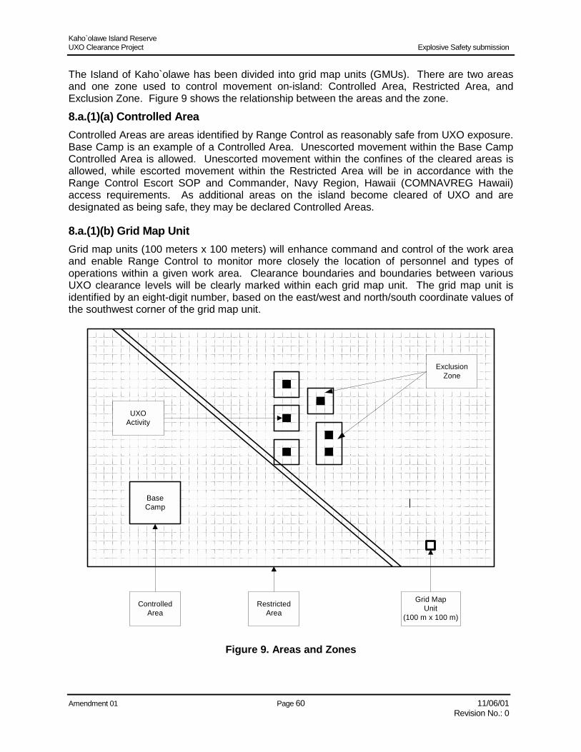
Kaho`olawe Island Reserve UXO Clearance Project Explosive Safety submission
Amendment 01 Page 60 11/06/01 Revision No.: 0
The Island of Kaho`olawe has been divided into grid map units (GMUs). There are two areas and one zone used to control movement on-island: Controlled Area, Restricted Area, and Exclusion Zone. Figure 9 shows the relationship between the areas and the zone.
8.a.(1)(a) Controlled Area Controlled Areas are areas identified by Range Control as reasonably safe from UXO exposure. Base Camp is an example of a Controlled Area. Unescorted movement within the Base Camp Controlled Area is allowed. Unescorted movement within the confines of the cleared areas is allowed, while escorted movement within the Restricted Area will be in accordance with the Range Control Escort SOP and Commander, Navy Region, Hawaii (COMNAVREG Hawaii) access requirements. As additional areas on the island become cleared of UXO and are designated as being safe, they may be declared Controlled Areas.
8.a.(1)(b) Grid Map Unit Grid map units (100 meters x 100 meters) will enhance command and control of the work area and enable Range Control to monitor more closely the location of personnel and types of operations within a given work area. Clearance boundaries and boundaries between various UXO clearance levels will be clearly marked within each grid map unit. The grid map unit is identified by an eight-digit number, based on the east/west and north/south coordinate values of the southwest corner of the grid map unit.
BaseCamp
ControlledArea
RestrictedArea
ExclusionZone
Grid MapUnit
(100 m x 100 m)
UXOActivity
Figure 9. Areas and Zones
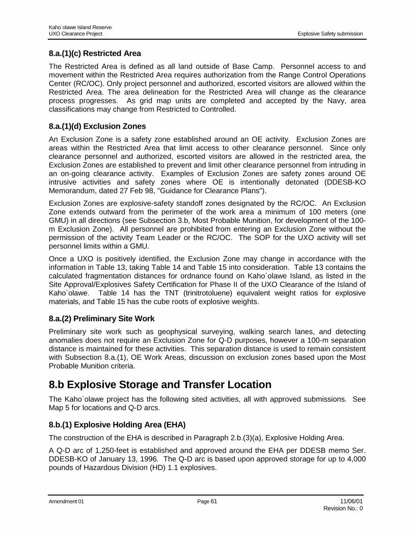
Kaho`olawe Island Reserve UXO Clearance Project Explosive Safety submission
Amendment 01 Page 61 11/06/01 Revision No.: 0
8.a.(1)(c) Restricted Area The Restricted Area is defined as all land outside of Base Camp. Personnel access to and movement within the Restricted Area requires authorization from the Range Control Operations Center (RC/OC). Only project personnel and authorized, escorted visitors are allowed within the Restricted Area. The area delineation for the Restricted Area will change as the clearance process progresses. As grid map units are completed and accepted by the Navy, area classifications may change from Restricted to Controlled.
8.a.(1)(d) Exclusion Zones An Exclusion Zone is a safety zone established around an OE activity. Exclusion Zones are areas within the Restricted Area that limit access to other clearance personnel. Since only clearance personnel and authorized, escorted visitors are allowed in the restricted area, the Exclusion Zones are established to prevent and limit other clearance personnel from intruding in an on-going clearance activity. Examples of Exclusion Zones are safety zones around OE intrusive activities and safety zones where OE is intentionally detonated (DDESB-KO Memorandum, dated 27 Feb 98, "Guidance for Clearance Plans"). Exclusion Zones are explosive-safety standoff zones designated by the RC/OC. An Exclusion Zone extends outward from the perimeter of the work area a minimum of 100 meters (one GMU) in all directions (see Subsection 3.b, Most Probable Munition, for development of the 100-m Exclusion Zone). All personnel are prohibited from entering an Exclusion Zone without the permission of the activity Team Leader or the RC/OC. The SOP for the UXO activity will set personnel limits within a GMU. Once a UXO is positively identified, the Exclusion Zone may change in accordance with the information in Table 13, taking Table 14 and Table 15 into consideration. Table 13 contains the calculated fragmentation distances for ordnance found on Kaho`olawe Island, as listed in the Site Approval/Explosives Safety Certification for Phase II of the UXO Clearance of the Island of Kaho`olawe. Table 14 has the TNT (trinitrotoluene) equivalent weight ratios for explosive materials, and Table 15 has the cube roots of explosive weights.
8.a.(2) Preliminary Site Work Preliminary site work such as geophysical surveying, walking search lanes, and detecting anomalies does not require an Exclusion Zone for Q-D purposes, however a 100-m separation distance is maintained for these activities. This separation distance is used to remain consistent with Subsection 8.a.(1), OE Work Areas, discussion on exclusion zones based upon the Most Probable Munition criteria.
8.b Explosive Storage and Transfer Location The Kaho`olawe project has the following sited activities, all with approved submissions. See Map 5 for locations and Q-D arcs.
8.b.(1) Explosive Holding Area (EHA) The construction of the EHA is described in Paragraph 2.b.(3)(a), Explosive Holding Area. A Q-D arc of 1,250-feet is established and approved around the EHA per DDESB memo Ser. DDESB-KO of January 13, 1996. The Q-D arc is based upon approved storage for up to 4,000 pounds of Hazardous Division (HD) 1.1 explosives.

Kaho`olawe Island Reserve UXO Clearance Project Explosive Safety submission
Amendment 01 Page 62 11/06/01 Revision No.: 0
Table 13. Calculated Fragmentation Distances for Some Ordnance Found on Kaho`olawe Fragmentation Distance
Ordnance Explosive Weight (lb) In Feet In Meters Explosive
2000 LB, SAP BOMB 556 4110 1252.7 PICRATOL MK 81 BOMB 100 3132 954.6 H-6 MK 82 BOMB 192 3894 1186.9 H-6 MK 83 BOMB 445 5153 1570.6 H-6 MK 84 BOMB 945 6623 2018.7 H-6 BLU-73 FAE 250 3149.8 960.1 TNT 40-LB FRAG BOMB 23 1421.9 433.4 TNT M 83 BUTTERFLY 0.5 527.8 160.9 COMP B FIRE BOMB 750 4542.8 1384.6 NAPALM BLU-61 BOMBLET 0.61 491.9 149.9 OCTOL 20-MM PROJECTILE 0.02 203.6 62.1 RDX 40-MM PROJECTILE 0.17 268.4 81.8 A-5 3”/50 PROJECTILE 0.74 452.3 137.9 TNT 5”/38 PROJECTILE 7.25 1306.4 398.2 COMP-A 5”/54 HE PROJECTILE 7.59 972.8 296.5 EXP D 5”/54 ILLUM PROJECTILE 8.2 1008.3 307.3 ILLUM 106-MM ILLUM PROJECTILE 2.79 936.2 285.4 COMP-B 105-MM HE PROJECTILE 7.76 989.9 301.7 COMP-B 105-MM ILLUM PROJECTILE 1.7 596.7 181.9 ILLUM 8” RAP RD PROJECTILE 12 1144.7 348.9 TNT 8” HE PROJECTILE 25 1462.0 445.6 TNT 16” PROJECTILE 153 2647.5 807.0 EXP D 81-MM HE MORTAR 4.3 813.1 247.8 TNT 81-MM ILLUM MORTAR 1.4 59.3 18.1 ILLUM 60-MM MORTAR 5 854.9 260.6 TNT 2.75” ROCKET WARHEAD 4.8 1121.8 341.9 COMP B 66-MM LAW 1 663.9 202.4 OCTOL 3.5” BAZOOKA 2.4 890.3 271.4 COMP B 5” HVAR ROCKET 20 1357.2 413.7 TNT 5” ZUNI ROCKET 9.1 1388.4 423.2 COMP B 4.5” BARRAGE ROCKET 6.5 933.1 284.4 TNT 4.2” ROCKET THROWN DEPTH CHARGE 15 1233.1 375.8 TNT 7.2” ROCKET THROWN DEPTH CHARGE 35 2257.0 687.9 TORPEX TOW MISSILE 6.8 1420.9 433.1 HMX DRAGON MISSILE 3.8 905.1 275.9 OCTOL AGM-12 BULL PUP MISSILE 284 4436.8 1352.3 PICRATOL AGM-45 SHRIKE MISSILE 44 1853.4 564.9 PBXN 101 MK 24 ACFT FLARE 16 1259.9 384.0 ILLUM MK 45 ACFT FLARE 17.6 1300.6 396.4 ILLUM 5” STAR SHELL (ILLUM) 11.2 118.7 36.2 ILLUM

Kaho`olawe Island Reserve UXO Clearance Project Explosive Safety submission
Amendment 01 Page 63 11/06/01 Revision No.: 0
Table 14. TNT Equivalent Weight Ratios for Explosive Materials Explosive Name Ratio
TNT 1.00 PICRATOL 1.00 TRITONAL 1.24
H-6 1.35 COMP B 1.33
EDNATOL 1.19 RDX 1.50
A-5 (A-3) 1.35 EXP D 0.99
COMP A (A-3) 1.35 OCTOL 1.16
TORPEX 1.38 HMX 1.50
PBXN-101 (104) 1.05
Table 15. Cube Roots of Explosive Weights Range of Total Explosive Weight of TNT or Equivalent
Between Pounds Pounds
Upper Limit Cube Root Based on the Highest Number of Pounds for a
Given Weight Range 0.0 1.0 1.00 1 2 1.26 2 5 1.71 5 10 2.15
10 20 2.71 20 30 3.11 30 40 3.42 40 50 3.68 50 100 4.64
100 200 5.85 200 300 6.69 300 400 7.37 400 500 7.94 500 600 8.43 600 700 8.88 700 800 9.28 800 900 9.65 900 1000 10.00
1000 1500 11.45 1500 2000 12.60 2000 3000 14.42
Kaho`olawe Island Reserve UXO Clearance Project Explosive Safety submission
Amendment 01 Page 64 11/06/01 Revision No.: 0
8.b.(2) Open Storage Area (OSA) The construction of the OSA is described in Paragraph 2.b.(3)(b), Open Storage Area. A Q-D arc of 1,250 feet is established and approved around the OSA per DDESB memo Ser. DDESB-KO of January 13, 1996. The Q-D arc is based upon approved storage for up to 20,000 pounds of HD 1.1 unexploded ordnance being held in temporary storage pending movement to the open burn/open detonation range.
8.b.(3) Inspection Point Location of the Inspection Point is described in Paragraph 2.b.(3)(c), Inspection Point. A Q-D arc of 1,250 feet is established and approved around the Inspection Point per DDESB memo Ser. DDESB-KO of January 13, 1996. The Q-D arc is based upon and approved for up to 5,000 pounds of HD 1.1 explosives.
8.b.(4) Ammunition Transfer Point (ATP) The number of the various ATPs and their locations are described in Paragraph 2.b.(3)(d), Ammunition Transfer Points. A Q-D arc of 1,250 feet is established and approved or each ATP on the island per DDESB memo Ser. DDESB-KO of January 13, 1996, DDESB memo Ser. DDESB-KO of January 28, 1997 and DDESB memo Ser. DDESB-KO of March 24, 2000. The Q-D arc is based upon and approved for transfer of up to 4,000 pounds of HD 1.1 explosives.
8.c Planned or Established Demolition Areas The Kaho`olawe project has the following sited activities, all with approved submissions. See Map 6, Demolition Areas Location, for locations and Q-D arcs.
8.c.(1) Open Burn Site The construction of the Open Burn Site is described in Paragraph 2.b.(4)(a), Open Burn. A Q-D arc of 1,250 feet is established and approved around the Open Burn Site per DDESB memo Ser. DDESB-KO of January 28, 1997. The Q-D arc is based upon and approved for up to 1,500 pounds of HD 1.1 munitions.
8.c.(2) Open Detonation Pits The construction of the Open Detonation Pits is described in Paragraph 2.b.(4)(b), Open Detonation. Disposal by detonation will be conducted in the pits and is approved for a total net explosive weight for all pits that may not exceed 1,000 pounds of HD 1.1 munitions per DDESB memo Ser. DDESB-KO of January 28, 1997. Mandatory evacuation distances for personnel not directly engaged in the demolition operation has been approved to vary according to the quantity and size of the munition as specified in Paragraph 13-3.2.1, NAVSEA OP 5, Volume 1 Fifth Edition, and Paragraph E.4, Chapter 5, DoD 6055.9-STD and summarized in Table 13.
8.c.(3) Thermal Processing Unit The construction of the Thermal Processing Unit is described in Paragraph 2.b.(4)(c), Thermal Processing Unit.
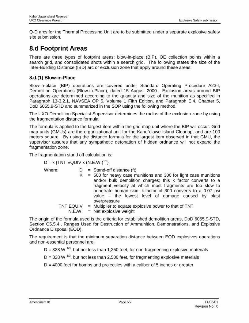
Kaho`olawe Island Reserve UXO Clearance Project Explosive Safety submission
Amendment 01 Page 65 11/06/01 Revision No.: 0
Q-D arcs for the Thermal Processing Unit are to be submitted under a separate explosive safety site submission.
8.d Footprint Areas There are three types of footprint areas: blow-in-place (BIP), OE collection points within a search grid, and consolidated shots within a search grid. The following states the size of the Inter-Building Distance (IBD) arc or exclusion zone that apply around these areas:
8.d.(1) Blow-in-Place Blow-in-place (BIP) operations are covered under Standard Operating Procedure A23-l, Demolition Operations (Blow-in-Place), dated 15 August 2000. Exclusion areas around BIP operations are determined according to the quantity and size of the munition as specified in Paragraph 13-3.2.1, NAVSEA OP 5, Volume 1 Fifth Edition, and Paragraph E.4, Chapter 5, DoD 6055.9-STD and summarized in the SOP using the following method. The UXO Demolition Specialist Supervisor determines the radius of the exclusion zone by using the fragmentation distance formula. The formula is applied to the largest item within the grid map unit where the BIP will occur. Grid map units (GMUs) are the organizational unit for the Kaho`olawe Island Cleanup, and are 100 meters square. By using the distance formula for the largest item observed in that GMU, the supervisor assures that any sympathetic detonation of hidden ordnance will not expand the fragmentation zone. The fragmentation stand off calculation is:
D = k {TNT EQUIV x (N.E.W.)1/3} Where: D = Stand-off distance (ft) K = 500 for heavy case munitions and 300 for light case munitions
and/or bulk demolition charges; this k factor converts to a fragment velocity at which most fragments are too slow to penetrate human skin; k-factor of 300 converts to a 0.07 psi value – the lowest level of damage caused by blast overpressure
TNT EQUIV = Multiplier to equate explosive power to that of TNT N.E.W. = Net explosive weight
The origin of the formula used is the criteria for established demolition areas, DoD 6055.9-STD, Section C5.5.4., Ranges Used for Destruction of Ammunition, Demonstrations, and Explosive Ordnance Disposal (EOD). The requirement is that the minimum separation distance between EOD explosives operations and non-essential personnel are:
D = 328 W 1/3, but not less than 1,250 feet, for non-fragmenting explosive materials D = 328 W 1/3, but not less than 2,500 feet, for fragmenting explosive materials D = 4000 feet for bombs and projectiles with a caliber of 5 inches or greater
Kaho`olawe Island Reserve UXO Clearance Project Explosive Safety submission
Amendment 01 Page 66 11/06/01 Revision No.: 0
Based upon the above equation the minimum Exclusion Zone (for one pound NEW TNT) is 500 feet for heavy-cased munitions, and 300 feet for light-cased munitions. Although the distances are less than the mandatory 1,250, 2,500, and 4,000 feet referenced above, they take into account that the entire island of Kaho`olawe is an OE area and that all persons on Kaho`olawe are project personnel or authorized, escorted visitors. The Exclusion Zones mandated in 6055.9 are established for public access and non-project personnel.
8.d.(2) Collection Points Collection points are authorized at the corner of each GMU for safe-to-move UXO. Only project personnel enter the Exclusion Zone around the collection points. The footprint areas for these collection points would use the same public separation distances as the most probable munition (MPM) for Kaho`olawe. Although there is no public access, the MPM for Kaho`olawe is a 40-mm projectile (see Subsection 3.b, Most Probable Munition). The Q-D arch is established at 100 m.
8.d.(3) In-Grid Consolidated Shots In-grid consolidated shots occur when recovered OE that is safe to move is collected and destroyed within a search grid. Consolidated shots use the Q-D as established in Paragraph 8.d.(1), Blow-in-Place.

Kaho`olawe Island Reserve UXO Clearance Project Explosive Safety submission
Amendment 01 Page 67 11/06/01 Revision No.: 0
Section 9 Off-Site Disposal There is no off-site disposal. All OE will be disposed of on-site.

Kaho`olawe Island Reserve UXO Clearance Project Explosive Safety submission
Amendment 01 Page 68 11/06/01 Revision No.: 0
This page intentionally left blank

Kaho`olawe Island Reserve UXO Clearance Project Explosive Safety submission
Amendment 01 Page 69 11/06/01 Revision No.: 0
Section 10 Technical Support Technical support for the Kaho`olawe UXO Clearance Project is provided both by Government agencies and contractors.
10.a Government Agencies 10.a.(1) Commander Naval Base Pearl Harbor The Commander in Chief, U.S. Pacific Command (USCINCPAC), designated the Commander, Naval Base Pearl Harbor (COMNAVBASE), the Regional Environmental Coordinator, plant account holder for Kaho`olawe, and the Department of Defense point of contact in Hawaii for the restoration and conveyance of Kaho`olawe. COMNAVBASE was directed by the Chief of Naval Operations (CNO) to negotiate with the State of Hawaii a Memorandum of Understanding and additional agreements required by the Memorandum of Understanding and Title X.
COMNAVBASE is the overall Program Manager and lead organization in all negotiation efforts with the State of Hawaii. COMNAVBASE coordinates, manages, and directs the development of the Kaho`olawe project to meet schedule, performance, and cost objectives. Other roles and responsibilities include:
• = Lead in all communications, especially those with the DoD, Congressional Delegation, Navy chain of command, State of Hawaii, Kaho`olawe Island Reserve Commission, media, and public
• = Compliance with Title X
• = Coordinate and develop with the State of Hawaii an acceptable ordnance clearance and restoration standard at various locations on Kaho`olawe
• = Complete any needed Navy/State agreements
• = Manage program funds
• = Control of access to the island
• = Coordinate and obtain ordnance clearance certification
10.a.(2) Pacific Division, Naval Facilities Engineering Command The Chief of Naval Operations directed the Pacific Division, Naval Facilities Engineering Command (PACNAVFACENGCOM), to provide technical assistance to COMNAVBASE. The Regional Officer in Charge of Construction (ROICC) provides field direction and technical representation. Figure 10 shows the PACNAVFACENGCOM – ROICC organization. PACNAVFACENGCOM is the project manager (execution agent) and provides technical and contracting services in support of the program objectives. PACNAVFACENGCOM responsibilities include:
• = Compliance with applicable State and Federal regulations, within the Regulatory Framework established by the Memorandum of Understanding
• = Technical support during Memorandum of Understanding negotiations
• = Task execution, including but not limited to:

Kaho`olawe Island Reserve UXO Clearance Project Explosive Safety submission
Amendment 01 Page 70 11/06/01 Revision No.: 0
ROICCContracting Officer
Alternate Contracting OfficerTechnical Representative
Contracting OfficerTechnical Representative
Alternate Contracting OfficerTechnical Representative
Alternate Contracting OfficerTechnical Representative(Archaeology On-Site, Mauibased)
Sr. Navy TechnicalRepresentative (UXO, Mauibased)
Project Manager
UXO Technical Manager(NAVEDOTECHDIV)
Contract Specialist (8 each)
Navy TechnicalRepresentative (On-Site,
UXO) 5 each
Figure 10. PACNAVFACENGCOM – ROICC Kaho`olawe Organizational Structure
– Preparation of the Navy’s Cleanup Plan – Completion of environmental assessments and clearances – Determination of the requirements and feasibility for environmental, health, and safety
requirements; providing constructability assessments, Cost/Risk Assessment Model, Database Record System, and clearance technology; awarding the UXO clearance contract; and managing contract requirements
– Generation of contract statements of work; provision of cost estimates and assessments of cost; development of criteria and methodology for evaluation of contract proposals; evaluation of contract proposals and vendor capabilities; establishment of an effective clearance/remediation quality control and quality assurance program; provision of quality assurance monitoring/assessment of clearance and remediation activities; coordination in developing PUXB performance evaluation input from COMNAVBASE, KIRC, and other affected activities; evaluation of construction performance; determination of award fee; review of contractor safety standards for UXO clearance and disposal operations; and development of ordnance identification guides for UXO clearance and disposal operations

Kaho`olawe Island Reserve UXO Clearance Project Explosive Safety submission
Amendment 01 Page 71 11/06/01 Revision No.: 0
– Provision of technical and budgetary status and technical briefings, as needed; coordination of the application of, and compliance with, DoD Explosive Safety Board requirements; provision of technical consulting, research, and analytical support; and management of funding within PACNAVFACENGCOM
– Assessment and determination of the most feasible contracting methodology to meet program objectives and serving as single point of contact on all contracting matters; providing contracting-officer support for award and administration of identified contracts; ensuring compliance with the statutes and regulations required in contract execution, administration, and close-out; and ensuring acquisition information/data is protected and held within proper channels, as stipulated in Federal Acquisition Regulations (FAR)
10.a.(3) Naval Explosive Ordnance Disposal Technology Division PACNAVFACENGCOM identified the Naval Explosive Ordnance Disposal Technology Division (NAVEODTECHDIV) as its technical consultant for the clearance, disposal, and remediation of unexploded ordnance on Kaho`olawe Island. NAVEODTECHDIV will execute taskings within, but not limited to, the following areas:
• = Acquisition, correlation, and maintenance of archival data, studies, and information concerning the prior use and history of ordnance on Kaho`olawe Island; completion of site surveys to acquire ordnance and explosive contamination data; and monitoring, integration, and archiving of ordnance data generated during the Kaho`olawe clearance and remediation efforts
• = Completion of assessments and/or analyses of current/emerging ordnance and explosive clearance and remediation technologies, as applicable to Kaho`olawe Island; completion of analyses of clearance feasibility; and establishment of in-situ test areas on Kaho`olawe to assess and validate existing, proposed, and emerging technologies
•= Provision of technical assistance during the generation of contract statements of work, cost estimates, and assessment of cost; development of criteria and matrices for the evaluation of contract proposals; participation in the evaluation of contract proposals and vendor capabilities; assistance in the establishment of an effective clearance/remediation quality control and quality assurance program; provision of quality assurance monitoring/assessment of clearance and remediation activities, contractor safety standards for UXO clearance and disposal operations, and ordnance identification guides as necessary for employment during UXO clearance and disposal operations
• = Provision of technical inputs to PACNAVFACENGCOM for inclusion in the Navy Cleanup Plan, technical, status, and budgetary reports, as required, and technical briefings, as needed; assistance in coordinating the application of, and compliance with, Department of Defense Explosive Safety Board requirements, as necessary; assurance that acquisition information/data is protected and held within channels as stipulated in Federal Acquisition Regulations; and provision of technical consulting, research, and analytical support to the Kaho`olawe effort as needed
10.a.(4) State of Hawaii The State of Hawaii is the land owner and sovereign government entity responsible for the long-term restoration and management of Kaho`olawe. The Kaho`olawe Island Reserve includes the island of Kaho`olawe and the submerged lands and waters extending seaward two nautical miles from the shoreline. The KIRC oversees the departments and agencies of the State with respect to control and management of the Kaho`olawe Island Reserve.
Kaho`olawe Island Reserve UXO Clearance Project Explosive Safety submission
Amendment 01 Page 72 11/06/01 Revision No.: 0
The KIRC is comprised of seven members appointed by the Governor of the State of Hawaii – one member of the PKO, two members from a list provided by the PKO, one trustee or representative from the Office of Hawaiian Affairs, one Maui County official, the Chair of the State Board of Land and Natural Resources, and one member from a list provided by native Hawaiian organizations. The KIRC’s function and responsibilities in the cleanup include:
• = Serving as the Navy’s single point of contact with the State and being consulted by the Navy for the review of, and input into, all aspects of planning and executing the cleanup
• = Preparing, in consultation with the Navy, and submitting a detailed Use Plan to the Navy for the entire island of Kaho`olawe that specifically identifies the uses to which each site or area on the island will be put (Kaho`olawe Use Plan, December, 1995) and, as part of this Use Plan, selecting sites or areas and identifying the priority of those sites or areas that are to be cleaned to the Tier II standard
•= Developing a Restoration Plan, in consultation with the Navy, (Kaho`olawe Environmental Restoration Plan, September, 1997) and coordinating it with the Navy’s development of the Cleanup Plan
• = Designating certain areas as off-limits or for limited access only for the protection of historical, cultural, and religious sites and artifacts, if required, in consultation with the Navy
• = Determining, in consultation with the Navy, the priority of clearance
• = Assisting the Navy in the identification of traditional cultural properties
• = Assisting the Navy in the assessment and determination of treatment for historic properties potentially impacted by the Cleanup
• = Providing cultural orientation to all project workers
• = Conducting any ceremonies or cultural protocol needed
• = Maintaining responsibility for the disposition of uncovered human remains
• = Independently monitoring the Cleanup project
• = Participating in the contract performance evaluation process
• = Cooperatively planning, with the Navy, all infrastructure improvements
• = Cooperatively developing, with the Navy, erosion and run-off control standards
10.b Parsons-UXB (PUXB) Joint Venture The Pacific Division, Naval Facilities Engineering Command, issued the Request for Proposal for the Unexploded Ordnance Clearance Project on Kaho`olawe Island Reserve, Hawaii, on December 13, 1996. Proposals were submitted by March 28, 1997. After carefully evaluating the proposals based on technical understanding, corporate experience and past performance, management, resources, and cost, the Pacific Division, Naval Facilities Engineering Command awarded the contract (Clearance Contract) to the Parsons-UXB Joint Venture (PUXB). The Clearance Contract was awarded on July 29, 1997.

Kaho`olawe Island Reserve UXO Clearance Project Explosive Safety submission
Amendment 01 Page 73 11/06/01 Revision No.: 0
10.b.(1) PUXB Background PUXB is a business registered in the State of Hawaii as a joint venture of Parsons Infrastructure & Technology (headquartered in Pasadena, California) and UXB International, Inc. (headquartered in Ashburn, Virginia). The PUXB team includes five additional team members: DynCorp (located in Reston, Virginia) and four Hawaii-based companies – Cultural Surveys Hawaii; Inc., Royal Contracting Company Ltd., Austin Tsutsumi & Associates Inc., and the University of Hawaii. These team members were chosen solely on the basis of their qualifications and expertise.
10.b.(2) PUXB Organization PUXB’s seamless organization integrates the joint venture partners and team members to promote clear lines of responsibility and authority, while ensuring there are no redundant layers of management. PUXB's team members will work to comply with the unique UXO-related and non-UXO-related technical and regulatory requirements of the contract scope of work. Team member participation will be delineated on a task-by-task basis. Members participating on a task order will mutually agree upon the technical approach for that task order, and the work assigned to each team member will remain with that team member for the duration of the task order. Team members report directly to the Program Manager or Senior Project Manager, depending on their functional areas of responsibility and assigned work elements.
10.b.(3) PUXB Management PUXB’s management team will organize, maintain, supervise, and direct a thoroughly trained, capable, and qualified work force to effectively perform the objectives of the contract and subsequent task orders. PUXB’s recruitment initiatives focus on (1) filling vacancies from our existing project organization, (2) recruiting from the local community, and (3) filling positions from our team’s corporate resources. Team members will recruit, hire, and promote all applicants for employment based on merit and qualifications, regardless of race, religion, national origin, age, gender, or handicap. Figure 11 illustrates the organizational structure of PUXB’s carefully selected and structured team. The following brief descriptions indicate each team members’ area of expertise and area of responsibility on this project. Following are the contractors providing OE technical support:
Parsons-UXBJoint Venture
UXB International,Inc.
ParsonsInfrastructure &
Technology
RoyalContracting
Company Ltd.DynCorp
Austin Tsutsumi& Associates
Inc.
University ofHawaii
Subcontractors/Vendors
Cultural SurveysHawaii, Inc.
Figure 11. PUXB Team Member Organizational Structure

Kaho`olawe Island Reserve UXO Clearance Project Explosive Safety submission
Amendment 01 Page 74 11/06/01 Revision No.: 0
Parsons Infrastructure & Technology, Inc. – For 50 years, Parsons Infrastructure & Technology, Inc. (Parsons) has been one of the world’s largest project management, engineering, and construction firms. Parsons’ areas of responsibility include compliance with the Regulatory Framework, UXO documentation, sampling, design of the infrastructure, data management, health and safety, program management, the contract management system, EE/CA preparation, environmental planning, status briefings, community relations, natural resources protection, quality control management, and non-UXO quality control. UXB International, Inc. – Founded in 1984 as the first civilian UXO contractor in the U.S., UXB International, Inc. (UXB), has more than 14 years of UXO experience. UXB is responsible for UXO clearance activities; range control; escort of visitors; health and safety; program management; handling and storing explosives; UXO quality control; status briefings; and community relations. Austin Tsutsumi & Associates, Inc. – Austin Tsutsumi & Associates, Inc. (ATA), is an Hawaiian small business with 62 years of engineering and surveying experience in Hawaii. ATA will provide civil engineering and land survey services.
10.b.(4) PUXB Management Offices The PUXB team members will collectively plan, manage, execute, and monitor the task orders of this project. PUXB’s management team is the core of the personnel plan. These management team members will be strategically located for efficient interaction with the Navy. PUXB’s Program Management Office (PMO) is configured to create a flexible environment that is responsive to the Navy’s expectations. The PMO is comprised of three locations with the following responsibilities.
• = The Program Management Office (PMO) (located at Pearl Harbor, Oahu) will serve as the overall program management office for this contract. This office’s management responsibilities include interface with the Navy; community relations (as requested), task order planning, prime contract management, subcontracting and procurement management, cost and schedule control and reporting, computer network management, financial management, cost reporting, infrastructure design, project management, base camp management, and closeout management.
• = The Maui Technical Office (MTO) (located at Kahului, Maui) will serve as the technical support office and logistics staging site for personnel and equipment. This office will provide technical design and support of all UXO and related activities on Kaho`olawe. This office’s management responsibilities include: Regulatory Framework compliance; staging island access and logistics; environmental planning; historic preservation, quality control, and safety programs; data and database management; data entry; task order planning; land survey; and task order documentation.
• = The Range Control/Operations Center (RC/OC) (located on Kaho`olawe Island) serves as the operations management office. The RC/OC will schedule, coordinate, and control all island operations, camp operations (through the Base Camp Manager), health and safety, access control, range control, communications, operation and maintenance, island security, UXO operations/processes, and construction operations.
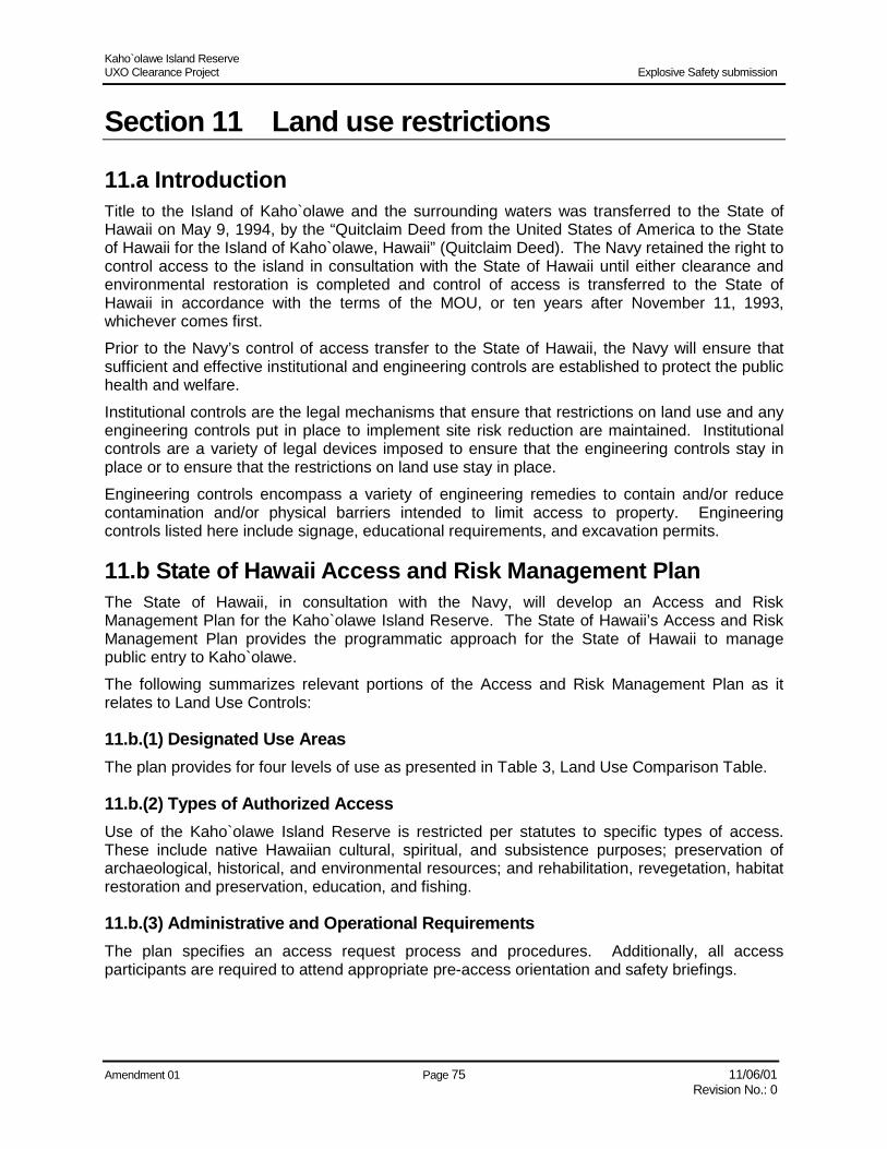
Kaho`olawe Island Reserve UXO Clearance Project Explosive Safety submission
Amendment 01 Page 75 11/06/01 Revision No.: 0
Section 11 Land use restrictions
11.a Introduction Title to the Island of Kaho`olawe and the surrounding waters was transferred to the State of Hawaii on May 9, 1994, by the “Quitclaim Deed from the United States of America to the State of Hawaii for the Island of Kaho`olawe, Hawaii” (Quitclaim Deed). The Navy retained the right to control access to the island in consultation with the State of Hawaii until either clearance and environmental restoration is completed and control of access is transferred to the State of Hawaii in accordance with the terms of the MOU, or ten years after November 11, 1993, whichever comes first. Prior to the Navy’s control of access transfer to the State of Hawaii, the Navy will ensure that sufficient and effective institutional and engineering controls are established to protect the public health and welfare. Institutional controls are the legal mechanisms that ensure that restrictions on land use and any engineering controls put in place to implement site risk reduction are maintained. Institutional controls are a variety of legal devices imposed to ensure that the engineering controls stay in place or to ensure that the restrictions on land use stay in place. Engineering controls encompass a variety of engineering remedies to contain and/or reduce contamination and/or physical barriers intended to limit access to property. Engineering controls listed here include signage, educational requirements, and excavation permits.
11.b State of Hawaii Access and Risk Management Plan The State of Hawaii, in consultation with the Navy, will develop an Access and Risk Management Plan for the Kaho`olawe Island Reserve. The State of Hawaii’s Access and Risk Management Plan provides the programmatic approach for the State of Hawaii to manage public entry to Kaho`olawe. The following summarizes relevant portions of the Access and Risk Management Plan as it relates to Land Use Controls:
11.b.(1) Designated Use Areas The plan provides for four levels of use as presented in Table 3, Land Use Comparison Table.
11.b.(2) Types of Authorized Access Use of the Kaho`olawe Island Reserve is restricted per statutes to specific types of access. These include native Hawaiian cultural, spiritual, and subsistence purposes; preservation of archaeological, historical, and environmental resources; and rehabilitation, revegetation, habitat restoration and preservation, education, and fishing.
11.b.(3) Administrative and Operational Requirements The plan specifies an access request process and procedures. Additionally, all access participants are required to attend appropriate pre-access orientation and safety briefings.

Kaho`olawe Island Reserve UXO Clearance Project Explosive Safety submission
Amendment 01 Page 76 11/06/01 Revision No.: 0
11.b.(4) Access Guide Requirements Escort requirements are defined and summarized in Table 16, Site-Specific Institutional Controls Matrix.
11.b.(5) Authorized Activities Authorized activities within specific use areas are dependent upon the level of clearance and certification. These are summarized in Table 16.
11.b.(6) Boundary Marking Mechanism. Preliminary requirements for boundary markers between the various use areas were developed and expanded and are discussed in Paragraph 11.c.(4), Boundary Markers.
11.b.(7) Reserve Monitoring Provisions will be supplied for long-term monitoring of the various use areas, restoration areas, and cultural sites to observe and collect information on the status and condition of Kaho`olawe’s facilities and resources. Another component of the monitoring program would include periodic monitoring for UXO within the various use areas.
11.b.(8) Legal and Statutory Control Mechanisms Provisions for State enforcement and statutory and administrative authority will be supplied.
11.b.(9) Institutional Control Program Matrix The State of Hawaii’s Access and Risk Management Plan is summarized in the matrix shown in Figure 12.
11.c Navy-Provided Institutional Controls Using the State of Hawaii’s Access and Risk Management Plan as a point of reference to better understand the requirements of the end-user, the following Navy-Provided Institutional Controls were developed to supplement the State of Hawaii’s Institutional Controls.
11.c.(1) Land Use Restrictions The May 1994 Deed specifies that “until such time as the United States, in accordance with the provisions of the MOU, certifies in one or more documents to the State that ordnance clearance or removal or environmental restoration actions under Title X and the MOU have been completed, areas that are not so certified to the State through documents recorded in the State Bureau of conveyances remain dangerous to the public and are not safe…” As ordnance clearance and environmental restoration is completed for each land parcel, appropriate documents will revise the land-use restrictions from “dangerous to the public and not safe” to an allowable use consistent with the ordnance clearance and environmental restoration. Allowed land use and restrictions for a parcel of land are determined by comparing the intended land use provided by the State of Hawaii and the resultant ordnance clearance against Table 2, UXO Clearance Tier Chart. Table 16, Site-Specific Institutional Controls Matrix summaries the land-use restrictions for each type of clearance and land use expected.

Kaho`olawe Island Reserve UXO Clearance Project Explosive Safety submission
Amendment 01 Page 77 11/06/01 Revision No.: 0
INSTITUTIONAL CONTROL PROGRAM MATRIX Waters Kaho`olawe Island
Zone
A
Zone
B
Leve
l 1
Leve
l 2
Leve
l 3
Leve
l 4
Uncleared Lands X X X
Surface (Tier I) X X
Clearance Depth
Subsurface – 4-Foot Depth (Tier II) X X
Between Shoreline & 30 Fathom Isobath X Reserve Waters
30 Fathom Isobath to Reserve Boundary X
Cultural Centers – Kahua Kauhale X
Overnight Campsites – Kahua Ho’omoana X
Constructed Trails and Roads X
Helicopter Landing Zones X
Select Restoration Areas & Nursery X
Improved Areas
Select Cultural Sites X
Unspecified Surface Restoration Areas X
Open Land X
Unimproved Areas
Unspecified Cultural Sites X
Uncleared Lands & Exception Areas X
Des
igna
ted
Use
Are
as
Management Areas
Hazardous Infrastructure (EHA, OSA, etc.) X
Fishing (Trolling) – Open Waters Schedule X
Steward Organization or KIRC-Lead X X X X X
Authorized Access
KIRC-Lead Only X
Vessel Registration & Reporting w/KIRC X
Access Request, Review, & Approval X X X X X
KIRC-Approved Safety Plan X X X X X
Pre-Access Orientation – Safety & Logistics X X X X X
Signed Waiver & Orientation Confirmation X X X X X
Arrival Check-In w/KIRC Operations X X X X X
Daily Location Report w/KIRC Operations X X X X X
Administrative & Operational Access
Requirements
Departure Check-Out w/KIRC Operations X X X X X
None (Presumes Authorized Access) X X
Steward Organization Guide or KIRC Guide X X
Access Guide Requirements
KIRC Guide Only X X
Figure 12. State of Hawaii Institutional Control Program Matrix

Kaho`olawe Island Reserve UXO Clearance Project Explosive Safety submission
Amendment 01 Page 78 11/06/01 Revision No.: 0
INSTITUTIONAL CONTROL PROGRAM MATRIX Waters Kaho`olawe Island
Zone
A
Zone
B
Leve
l 1
Leve
l 2
Leve
l 3
Leve
l 4
Non-Intrusive – Transit, Culture, & Education X X X X X
Intrusive – Culture & Education X X
Intrusive – Environmental Restoration (Tier II Only) X X
Intrusive – Infrastructure (Tier II Only) X X
Authorized Activities
Select KIRC-Lead Only X X
Children (12 or younger) 1:1 Adult-Child Ratio X X X X
Teens (13-17) 5:1 Adult-Teen Ratio X X X X X
Age Limits & Supervision Ratios
Adults (Persons 18 or older) X X X X X X
Public Outreach, Brochures, & Website X X X X X X
Signage, Notices, & Informational Displays X X X X X X
Map or Navigational Chart X X X X X X
Hand-Held GPS or Compass X X X X X
Survey Stakes – PUXB Metes & Bounds X X X X
Recycled Plastic Posts – Visual Markers X X X
Stone Alignments – Level 2 Trails X
Stone Cairns – Visual Reference Markers X X X
Boundary Notice & Marking Mechanisms
Fencing – Hazardous Infrastructure Only X
On-Going KIRC Operations & Program Monitoring X X X X X X
Semi-Annual UXO Monitoring X
Annual UXO Monitoring X X
Access-Specific UXO Monitoring X X
Reserve Monitoring
Post-Environmental Event UXO Monitoring X X X
Figure 12. State of Hawaii Institutional Control Program Matrix (Continued)
Additionally, Hawaii Administrative Rules, Section 13-260, restricts permitted uses of the Kaho`olawe Island Reserve to the following:
• = Customary and traditional native Hawaiian cultural, spiritual, and subsistence use in areas deemed safe
• = Activities for the preservation, protection, and restoration of cultural, archaeological, and historical sites
• = Rehabilitation, revegetation, habitat restoration, and preservation
• = Educational activities

Kaho`olawe Island Reserve UXO Clearance Project Explosive Safety submission
Amendment 01 Page 79 11/06/01 Revision No.: 0
11.c.(2) Restrictive Covenants Navy policy regarding land use controls requires that the United States ensure that institutional controls “run with the land,” such that the immediate transferee and subsequent transferees are required to abide by the institutional controls. The form of the restricted covenant is determined by state real property law. The exact form of the restrictive covenant is subject to discussion between the State of Hawaii and the Navy.
11.c.(3) Coastal Warning Signs Sixteen aluminum coastal warning signs (3’ x 5’-6”) are established around the perimeter of Kaho`olawe (Figure 13). The locations for these signs were selected as the most likely points of entry to the island.
11.c.(4) Boundary Markers Effective boundary markers provide the following information:
• = Delineates the clearance boundary of the land parcel
• = Provides adequate warning and information about land use restrictions and dangers The following types of boundary markers are proposed.
Figure 13. Coastal Warning Signs

Kaho`olawe Island Reserve UXO Clearance Project Explosive Safety submission
Amendment 01 Page 80 11/06/01 Revision No.: 0
11.c.(4)(a) Type 1: Cultural Centers/Overnight Camp Sites Level 1 areas are subsurface cleared to four (4) feet and are expected to have the highest use and visitation to Kaho`olawe. Level 1 areas will be surrounded by areas that have been surface-swept of UXO. The purpose of the Type 1 boundary markers (Figure 14) is to delineate the extent of unescorted access around the cultural centers and overnight camping areas.
Designed Use Area: Level 1: Cultural centers and overnight campsites OE Removal Depth: 4 feet Boundary Marker Construction: 4” x 4” x 48” neutral-colored recycled plastic post Installation Guidelines: Posts to be installed within a visible sight distance of
one another Land Use Restriction: Intrusive activities to 12 inches permitted Access Guide Restrictions: None
4123
4123
CAUTION
C A U T I O N
DO NOT PROCEED BEYOND THIS POINTW/O AUTHORIZED ESCORT
Neutral colored recycled plastic post
48"
4"
4"
Post Identification Number
Custom printer reflective labels
Example Warning Signs for Level 1 Areas(Cultural Areas and Overnight Campsites)
Figure 14. Typical Type 1 Boundary Marker for Level 1 Areas

Kaho`olawe Island Reserve UXO Clearance Project Explosive Safety submission
Amendment 01 Page 81 11/06/01 Revision No.: 0
11.c.(4)(b) Type 2A: Frequent Transits Areas (Roads) Level 2 areas include areas used for environmental and cultural restoration, trails and roads, and helicopter landing zones. For improved roads and helicopter landing zones, the limits of the improvements are the boundaries for visitor access. The purpose of the Type 2a boundary markers (Figure 15) is to notify users of the road or improved helicopter landing zones to remain within the improved sections of the road or landing zone. Since the limits of the improved road are readily identifiable, signage warning to remain on the road may be spaced at intervals up to ½ mile. A single warning sign at each improved helicopter landing zone will notify arrivals to remain within marked paths and designated areas. Designed Use Area: Level 2: Roads and helicopter landing zone OE Removal Depth: 4 feet Boundary Marker Construction: Roadside signage along improved roads
Warning sign at each helicopter landing zone Installation Guidelines: Signage along improved roads up to ½ mile interval
Warning sign at each improved helicopter landing zone Land Use Restriction: Public access, vehicular traffic, road maintenance
activities permitted Access Guide Restrictions: KIRC or stewardship-organization guide
Lua Makika Helicopter Landing Zone
CAUTIONRemain within all marked pathways and designated
areasKaho`olawe Island Reserve, Hawaii
2'-0"
3'-0"
Example Warning Sign for Improved Helicopter Landing Zone
K-1 RoadCAUTION
Remain within road cooridorKaho`olawe Island Reserve, Hawaii
2'-0"
Example Warning Sign for Improved Roadways
2'-0"
1'-6"
2'-0"
Figure 15: Typical Type 2 Boundary Markers for Roads and Helicopter Landing Zones

Kaho`olawe Island Reserve UXO Clearance Project Explosive Safety submission
Amendment 01 Page 82 11/06/01 Revision No.: 0
11.c.(4)(c) Type 2B: Frequent Transit Areas (Trails) Designated trails are constructed within a five-meter clearance corridor that has been cleared to an OE removal depth of 12 inches. The trails are constructed within the clearance corridor by edging the trail boundaries with rocks and stones gathered from the surface within the cleared region. An informational post is then established along the centerline of the trail to help identify the trail. Figure 16 shows typical Type 2B boundary markers for trails. The purpose of the informational post is to remind users to remain within the trail corridor bounded by the stone alignments. Since the stone alignments indicate the limits of access along the trail, the informational post only aids with identifying the trail pathway and can be set at distances greater than within visual sight of one another.
4123
CAUTION
REM
AIN O
N TR
AIL PATHW
AY
4123CAUTION
48"
4"
4"Post IdentificationNumber
Stone Alignment
Greater than visual distance
4124CAUTION
Trail CenterlineNeutral-colored recycledplastic post
Custom printed reflective labesl
Labels on sides facing trail
Approximately 5-m clearance cooridor (12" removal depth)
Figure 16. Typical Type 2B Boundary Markers for Trails
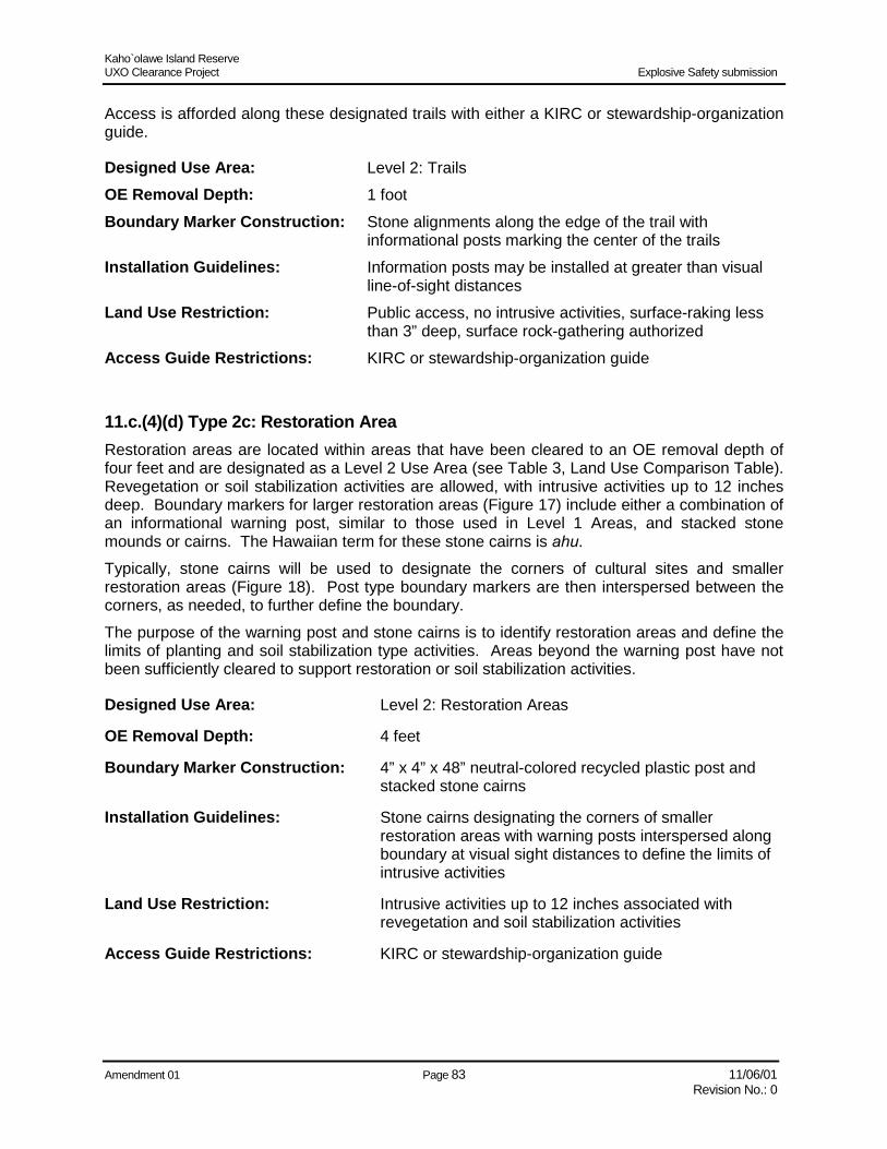
Kaho`olawe Island Reserve UXO Clearance Project Explosive Safety submission
Amendment 01 Page 83 11/06/01 Revision No.: 0
Access is afforded along these designated trails with either a KIRC or stewardship-organization guide.
Designed Use Area: Level 2: Trails OE Removal Depth: 1 foot Boundary Marker Construction: Stone alignments along the edge of the trail with
informational posts marking the center of the trails Installation Guidelines: Information posts may be installed at greater than visual
line-of-sight distances Land Use Restriction: Public access, no intrusive activities, surface-raking less
than 3” deep, surface rock-gathering authorized Access Guide Restrictions: KIRC or stewardship-organization guide
11.c.(4)(d) Type 2c: Restoration Area Restoration areas are located within areas that have been cleared to an OE removal depth of four feet and are designated as a Level 2 Use Area (see Table 3, Land Use Comparison Table). Revegetation or soil stabilization activities are allowed, with intrusive activities up to 12 inches deep. Boundary markers for larger restoration areas (Figure 17) include either a combination of an informational warning post, similar to those used in Level 1 Areas, and stacked stone mounds or cairns. The Hawaiian term for these stone cairns is ahu. Typically, stone cairns will be used to designate the corners of cultural sites and smaller restoration areas (Figure 18). Post type boundary markers are then interspersed between the corners, as needed, to further define the boundary. The purpose of the warning post and stone cairns is to identify restoration areas and define the limits of planting and soil stabilization type activities. Areas beyond the warning post have not been sufficiently cleared to support restoration or soil stabilization activities.
Designed Use Area: Level 2: Restoration Areas
OE Removal Depth: 4 feet
Boundary Marker Construction: 4” x 4” x 48” neutral-colored recycled plastic post and stacked stone cairns
Installation Guidelines: Stone cairns designating the corners of smaller restoration areas with warning posts interspersed along boundary at visual sight distances to define the limits of intrusive activities
Land Use Restriction: Intrusive activities up to 12 inches associated with revegetation and soil stabilization activities
Access Guide Restrictions: KIRC or stewardship-organization guide
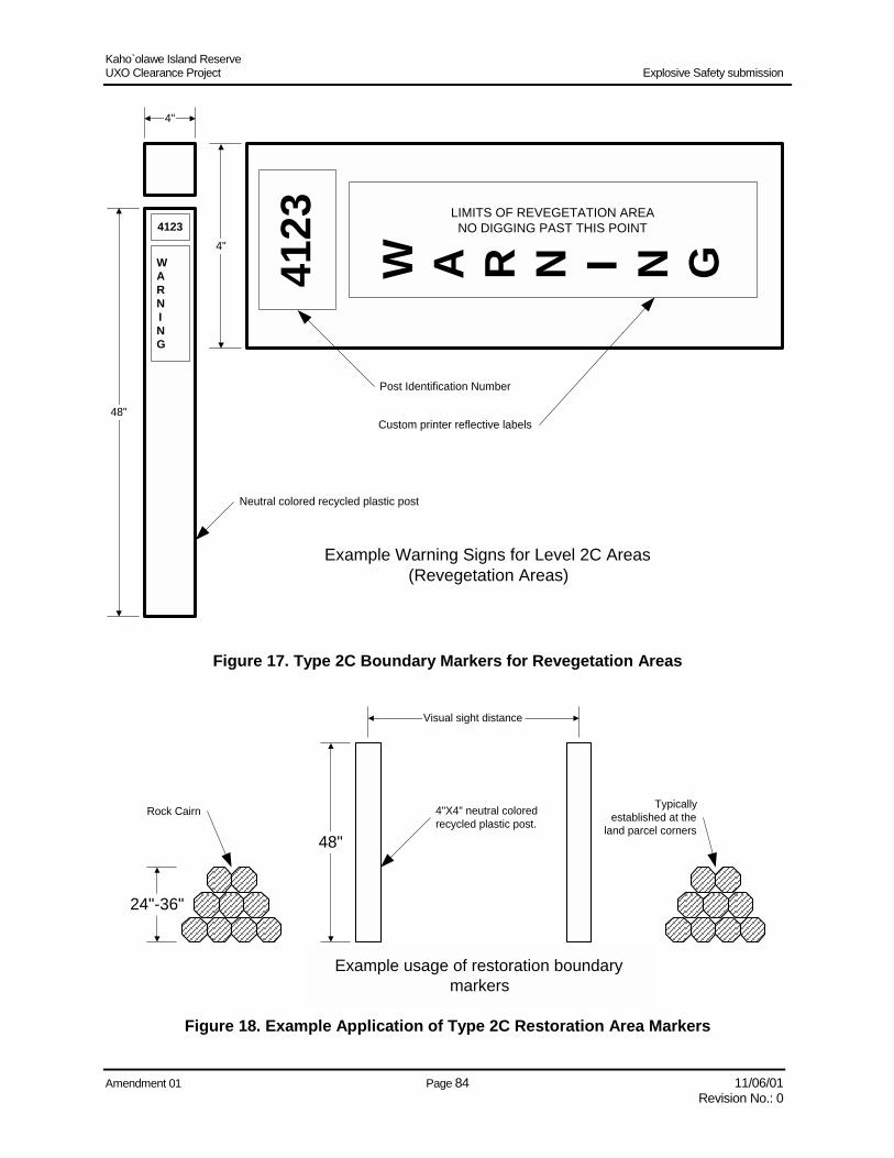
Kaho`olawe Island Reserve UXO Clearance Project Explosive Safety submission
Amendment 01 Page 84 11/06/01 Revision No.: 0
4123
4123
WARNING
W A R N I N G
LIMITS OF REVEGETATION AREANO DIGGING PAST THIS POINT
Neutral colored recycled plastic post
48"
4"
4"
Post Identification Number
Custom printer reflective labels
Example Warning Signs for Level 2C Areas(Revegetation Areas)
Figure 17. Type 2C Boundary Markers for Revegetation Areas
24"-36"
48"
Rock Cairn
Visual sight distance
Example usage of restoration boundarymarkers
4"X4" neutral coloredrecycled plastic post.
Typicallyestablished at the
land parcel corners
Figure 18. Example Application of Type 2C Restoration Area Markers

Kaho`olawe Island Reserve UXO Clearance Project Explosive Safety submission
Amendment 01 Page 85 11/06/01 Revision No.: 0
11.c.(4)(e) Type 3: Open Lands (Level 3) No boundary markers are required to delineate Level 3 areas. A Level 3 area is either bounded or encompasses other use areas and will be delineated by the other use-area’s boundary markers.
Designed Use Area: Open Lands
OE Removal Depth: Surface only
Boundary Marker Construction: None
Installation Guidelines: None
Land Use Restriction: Limited access mound plantings, low intensity, and no intrusive activities
Access Guide Restrictions: Limited access with EOD/UXO escorts
11.c.(4)(f) Type 4: Special Management Areas (Level 4) Special Management Areas have not been cleared and remain hazardous. No changes to the May 1994 deed regarding land use will be made for these parcels. Boundary markers used to identify uncleared areas (Figure 19) need to be highly visible and readily identifiable. Since a major portion of the areas left uncleared are due to vegetation, terrain, or slope limitations, a lightweight and easily installable polymeric tube marker is proposed to ease installation. Custom-printed reflective decals provide warning and notice information.
48"
WARNING
4123
W A R N I N G4123
RESTRICTED AREAUNEXPLODED ORDNANCE DANGER
AUTHORIZED ACCESS ONLY
3.5" O.D.
3..5" O.D.
Custom printed reflective labels
UV Resistant polymeric tube marker
Black Thermoplastic cap
Example Warning Signs for Level 4 AreasSpecial Management Areas
(Uncleared Areas)
Figure 19. Type 4 Boundary Marker for Uncleared Areas
Kaho`olawe Island Reserve UXO Clearance Project Explosive Safety submission
Amendment 01 Page 86 11/06/01 Revision No.: 0
Designed Use Area: Special management areas OE Removal Depth: No clearance completed Boundary Marker Construction: Highly visible polymeric tube markers with custom-printed
reflective labels. Installation Guidelines: To be set along the perimeter of uncleared areas at visual
sight distances of one another Land Use Restriction: Area remains hazardous with restricted access and no
intrusive activities Access Guide Restrictions: Restricted access with EOD/UXO escorts only
11.c.(4)(g) Type 1 Exception Areas: Surface-Cleared Exception Areas Type 1 Exception Areas are surface-cleared areas within subsurface clearance areas. By definition, Type 1 Exception Areas can only be located within Level 1 or Level 2 Use Areas. Due to technical limitations, terrain, or obstructions, subsurface clearance was not conducted within specific portions of a Level 1 or Level 2 Use Area that were designated for subsurface clearance. Boundary markers around these areas need to notify that no digging or other intrusive activities are allowed within these exception areas. Type 2C Restoration Area Boundary Markers provide the necessary information and can be used in this situation. Designed Use Area: Unspecified/undesignated restoration areas, undeveloped
coastal corridors, and open lands OE Removal Depth: Surface only Boundary Marker Construction: Warning posts interspersed along the boundary at a visual
sight distance to define the limits of intrusive activities Installation Guidelines: To be set along the perimeter of the exception area at
visual sight distances of one another. Land Use Restriction: Limited access mound plantings, low intensity, and no
intrusive activities Access Guide Restrictions: Limited access with EOD/UXO escorts
11.c.(4)(h) Type 2 Exception Areas: Uncleared Exception Areas Type 2 Exception Areas are uncleared areas within either surface- or subsurface-cleared areas. Type 2 Exception Areas can be located within either Type 1, 2, or 3 Use Areas. These areas have not been cleared due to technical limitations, terrain, or obstructions. Boundary markers around these areas need to notify that these areas are uncleared and remain hazardous. Type 4 Special Management Area Boundary Markers with the necessary information can be used in this situation.
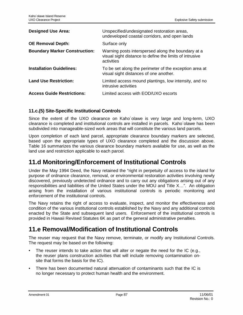
Kaho`olawe Island Reserve UXO Clearance Project Explosive Safety submission
Amendment 01 Page 87 11/06/01 Revision No.: 0
Designed Use Area: Unspecified/undesignated restoration areas, undeveloped coastal corridors, and open lands
OE Removal Depth: Surface only Boundary Marker Construction: Warning posts interspersed along the boundary at a
visual sight distance to define the limits of intrusive activities
Installation Guidelines: To be set along the perimeter of the exception area at visual sight distances of one another.
Land Use Restriction: Limited access mound plantings, low intensity, and no intrusive activities
Access Guide Restrictions: Limited access with EOD/UXO escorts
11.c.(5) Site-Specific Institutional Controls Since the extent of the UXO clearance on Kaho`olawe is very large and long-term, UXO clearance is completed and institutional controls are installed in parcels. Kaho`olawe has been subdivided into manageable-sized work areas that will constitute the various land parcels. Upon completion of each land parcel, appropriate clearance boundary markers are selected, based upon the appropriate types of UXO clearance completed and the discussion above. Table 16 summarizes the various clearance boundary markers available for use, as well as the land use and restriction applicable to each parcel.
11.d Monitoring/Enforcement of Institutional Controls Under the May 1994 Deed, the Navy retained the “right in perpetuity of access to the island for purpose of ordnance clearance, removal, or environmental restoration activities involving newly discovered, previously undetected ordnance and to carry out any obligations arising out of any responsibilities and liabilities of the United States under the MOU and Title X…”. An obligation arising from the installation of various institutional controls is periodic monitoring and enforcement of the institutional controls. The Navy retains the right of access to evaluate, inspect, and monitor the effectiveness and condition of the various institutional controls established by the Navy and any additional controls enacted by the State and subsequent land users. Enforcement of the institutional controls is provided in Hawaii Revised Statutes 6K as part of the general administrative penalties.
11.e Removal/Modification of Institutional Controls The reuser may request that the Navy remove, terminate, or modify any Institutional Controls. The request may be based on the following:
• = The reuser intends to take action that will alter or negate the need for the IC (e.g., the reuser plans construction activities that will include removing contamination on-site that forms the basis for the IC).
• = There has been documented natural attenuation of contaminants such that the IC is no longer necessary to protect human health and the environment.

Kaho`olawe Island Reserve UXO Clearance Project Explosive Safety submission
Amendment 01 Page 88 11/06/01 Revision No.: 0
Table 16. Site-Specific Institutional Controls Matrix Designated Use Areas
Intended Land Use
Removal Depth
Allowed Land Use and Restrictions
Boundary Markers
Access Guide Requirements
1 Cultural centers and overnight camping
4 feet Intrusive activities to 12 inches permitted
Type 1 None Required
Frequent transit areas (roads, helicopter landing zones)
4 feet Public access, vehicular traffic, road maintenance activities permitted
Type 2A KIRC or stewardship-organization guide
Frequent transit areas (trails)
1 foot Public access, no intrusive activities, surface raking less than 3 inches deep, surface rock gathering authorized
Type 2B KIRC or stewardship-organization guide
2
Restoration area 4 feet Intrusive activities to 12 inches permitted
Type 2C KIRC or stewardship-organization guide
3 Unspecified/ undesignated restoration areas, undeveloped coastal corridors, and open lands
Surface only
Restricted use, no intrusive activities
None* Limited access EOD/UXO escort only
4 Special management areas
No clearance
Area remains hazardous with restricted access and no intrusive activities
Type 4 Restricted access EOD/UXO escort only
Type 1 Exception
Area
Unspecified/ undesignated restoration areas, undeveloped coastal corridors and open lands
Surface only
Restricted use, no intrusive activities
Type 2C Limited access EOD/UXO escort only
Type 2 Exception
Area
None No clearance
Area remains hazardous with restricted access and no intrusive activities
Type 4 Restricted access EOD/UXO escort only
Kaho`olawe Island Reserve UXO Clearance Project Explosive Safety submission
Amendment 01 Page 89 11/06/01 Revision No.: 0
Section 12 Public involvement
12.a Public Participation Agreement The Navy and the KIRC, on behalf of the State, developed an agreement regarding public participation, in accordance with the requirements of the MOU. This Public Participation Agreement also serves to meet the substantive requirements of the Comprehensive Environmental Response, Compensation and Liability Act (CERCLA) as related to the development of a Community Relations Plan (Public Participation Agreement for Actions Undertaken Pursuant to the May 6, 1994, Memorandum of Understanding between the Navy and the State of Hawaii Concerning the Island of Kaho`olawe, Hawaii). Through implementation of the Public Participation Agreement, community involvement and communication with the community are promoted through providing information in a timely manner, soliciting public comments, and considering those comments in the decision-making process.
12.b Public Meeting At the KIRC’s monthly public meetings, the KIRC affords the Navy, by way of a published agenda item entitled “Navy Report,” an opportunity to: (1) provide the public with updated information concerning the cleanup, (2) receive public comments, and (3) respond to significant public inquiries raised regarding the cleanup.
12.c Kaho`olawe Cleanup Plan Public Review The Navy made the Cleanup Plan readily available to the public for a review and comment for period of not less than 30 calendar days.
• = During the comment period, the KIRC assisted the Navy in presenting the Cleanup Plan in public meetings on O`ahu, Maui, Molaka`i, Lana`i, Hawai`i, and Kaua`i.
• = The KIRC sponsored and provided notice of the meetings in consultation with the Navy. The Navy was able to provide additional notice in consultation with the KIRC. PUXB supported the Navy when the Cleanup Plan was presented for public comment and when the Navy attended the KIRC meetings.
• = The Navy solicited public comments and prepared written responses to significant comments.
• = The Cleanup Plan, public comments, and written responses were included in the administrative record file.
12.d Administrative Record The Navy established an Administrative Record file and published a notice of its availability for public inspection and comment in a major local newspaper. The Cleanup Plan and Engineering Trade-Off Analysis are available for public review at the following locations:

Kaho`olawe Island Reserve UXO Clearance Project Explosive Safety submission
Amendment 01 Page 90 11/06/01 Revision No.: 0
Island of Hawaii: Kailua – Kona Library Hilo Regional Library 76-140 Hualalai Road P. O. Box 647 Kailua-Kona, HI 96740 Hilo, HI 96720
Island of Maui: Wailuku Regional Library Lahaina Library P. O. Box B 680 Wharf Street Wailuku, HI 96793 Lahaina, HI 96761
Hana School and Community Library Hana High School and Elementary Campus Hana Highway Hana, HI
Island of Lanai: Lanai Public and School Library P. O. Box A-149 Lanai, HI 96763
Island of Molokai: Molokai Library P. O. Box 395 Kaunakakai, HI 96748
Island of Oahu: Kaho`olawe Island Reserve Commission State Main Library 33 South King Street, Suite 501 478 South King Street Honolulu, HI 96813 Honolulu, HI 96813
Kaimuki Regional Library Kaneohe Regional Library 1041 Koko Head Avenue 45-829 Kamehameha Highway Honolulu, HI 96816 Kaneohe, HI 96744
Pearl City Regional Library 1138 Waimano Home Road Pearl City, HI 96782
Island of Kauai: Kauai Regional Library 4344 Hardy Street Lihue, HI 96766
The Cleanup Plan is available on the Internet website of the Pacific Division, Naval Facilities Engineering Command at:
http://www.efdpac.navfac.navy.mil Click on “PACDIV News,” and a Kaho`olawe icon will appear. Click on the icon, and choose either of two options: “Cleanup Plan” or “ETA.”

Kaho`olawe Island Reserve UXO Clearance Project Explosive Safety submission
Amendment 01 Page 91 11/06/01 Revision No.: 0
Section 13 References American Society for Quality Control
1994 American National Standard, Specifications and Guidelines for Quality Systems for Environmental Data Collection and Environmental Technology Programs, ANSI/ASQC E4-1994, Milwaukee, Wisconsin
Cassidy, W.J., Retz, W.A., Waihee, J., and N.E. Aluli 1994 "Memorandum of Understanding Between the United States Department of the
Navy and the State of Hawaii Concerning the Island of Kaho`olawe, Hawaii", recorded at the State of Hawaii Bureau of Conveyances, May 6, 1994
Department of Defense 1993 Public Law 103-139, 107 STAT 1418, 1479-1484, FY 94 Defense
Appropriations Act, Title X, "Conveyance of Kaho`olawe Island, Hawaii, to the State of Hawaii", signed 11 NOV 1993
1996 Department of Defense Test Method Standards, DoD Preferred Methods for Acceptance of Product, MIL-STD-1916, dated April 1, 1996
1996 DoD 6055.9-STD: DoD Ammunition and Explosives Safety Standards, Chapter 12-Real Property Contaminated with Ammunition and Explosives, June 19, 1996
Department of Defense, Explosive Safety Board 1998 “ Guidance for Clearance Plans”, memorandum dated January 27, 1998
Department of the Navy 1980 Consent Decree, Aluli et al. V. Brown; Civil suit no. 76-0380 1994 Appendix A., Applicable requirements, In, Regulatory Framework Pursuant to
the May 6, 1994, Memorandum Of Understanding Between the United States Department of the Navy and the State of Hawaii Concerning the Island of Kaho`olawe, Hawaii
1994 Environmental and Natural Resources Program Manual, OPNAVINST 5090.1B, Office of the Chief of Naval Operations, Washington, D.C
1994 Regulatory Framework Pursuant to the May 6, 1994, Memorandum of Agreement between the United States Navy and the State of Hawaii Concerning the Island of Kaho`olawe"
1994 Memorandum of Understanding (MOU) between the United States Navy and the State of Hawaii/Quitclaim Deed from the United States to the State of Hawaii, May 6, 1994
Geophysical Technology Limited 2000 “State of the Art Technologies for the detection of Sub-surface Unexploded
Ordnance,” GTL Technical Note No: 5

Kaho`olawe Island Reserve UXO Clearance Project Explosive Safety submission
Amendment 01 Page 92 11/06/01 Revision No.: 0
Kaho`olawe Island Reserve Commission 2001 Priorities and Sequencing Plan, dated July 7, 2000 2001 “Initial Summary of Engineering Controls for the Kaho`olawe Island Reserve,”
October 11, 2001 Nakamura, S., and C. W. Smith
1995 Soil Survey of Island of Kaho`olawe, Hawaii; Natural Resources Conservation Service, U.S. Dept. of Agriculture and the U.S. Naval Facilities Engineering Command, Pacific Division, Honolulu, Hawaii
Naval Explosive Ordnance Disposal Technology Division 1998 Kaho`olawe Site Characterization (SC) for Unexploded Ordnance (UXO),
Three volumes. Prepared for the Naval Facilities, Pacific Engineering Command, Pearl Harbor, Hawaii. Naval Explosive Ordnance Disposal Technology Division, Indian Head, Maryland
Parsons-UXB Joint Venture
1998 Cleanup Plan UXO Clearance Project, Kaho`olawe Island Reserve, Hawaii. Prepared for Pacific Division, Naval Facilities Engineering Command, Kapiolani, Hawaii
PBR Hawaii 1995 Palapala Ho`onohonoho Moku`āina o Kaho`olawe, Kaho`olawe Use Plan,
Kaho`olawe Island Reserve Commission, Honolulu, Hawaii OHM Remediation Service Corporation
1996a Unexploded Ordnance (UXO) Model Clearance Project Kaho`olawe Island, Hawaii, Volume I (Final Report) and Volume II (Lessons Learned). Prepared for Pacific Division, Naval Facilities Engineering Command, Kapolei, Hawaii
1996b Unexploded Ordnance (UXO) Model Clearance Project Kaho`olawe Island, Hawaii, Protective Works Demonstration Report. Prepared for Pacific Division, Naval Facilities Engineering Command, Kapolei, Hawaii
1996c Unexploded Ordnance (UXO) Model Clearance Project, Island of Kaho`olawe, Clearance Results Map. Prepared for Pacific Division, Naval Facilities Engineering Command, Kapolei, Hawaii
1996d UXO Model Clearance Project Kaho`olawe Island, Hawaii Access Data Base Files. Prepared for Pacific Division, Naval Facilities Engineering Command, Kapolei, Hawaii
United States Environmental Protection Agency, Quality Assurance Division 1997 EPA Requirements for Quality Assurance Project Plans for Environmental Data
Operations, EPA QA/R-5, Washington, D.C.