expressive gypsum ceilings - boydemyapi.com · creating expressive ceilings expressive gypsum...
TRANSCRIPT
creat ing express ive cei l ings
w w w . d a n o l i n e . c o m
Expressivegypsumceilings
Expressive gypsum ceilings
CI/Sfb: (35)
C o n t e n t s
PrefaceDanoline, history, possibilities Page 3
Products
SuSPEndEd CEIlIngS
Contur 600 Page 12
Linear 600 Page 16
Markant 500 and 600 Page 20
Belgravia 600 Page 26
Plaza 600 Page 30
Danoline tiles 600, White and Metallic Page 34
Danoline tiles 600, Medley Page 36
ACCESSorIES
Danopor Page 40
SElf-SuPPortIng CEIlIngS
Corridor 300 Page 42
Corridor F30 Page 46
Corridor Swing 600 Page 50
lInIngS
Danopanel Page 54
Combipanel Page 58
Designpanel 900 and 1200 Page 62
Tectopanel Page 66
Contrapanel Page 70
Kinopanel Page 74
Solopanel and Stratopanel Page 82
dESIgnElEmEntS
Curvex Page 78
Mitex Page 80
Properties
SurfACIng
Gypsum as a natural palette Page 88
ACouStICS
Gypsum regulates sound Page 90
fIrE
Gypsum as nature’s sprinkler Page 98
Indoor ClImAtE And EnvIronmEnt
Gypsum can breathe Page 100
loAd-bEArIng CAPACIty And wEIght
Gypsum as a weightlifter Page 102
moISturE
Gypsum as a natural skin Page 104
lumInouS rEflECtAnCE
Gypsum mirrors the light Page 106
PerforationsPerforations and patterns Page 111
Globe, G Page 112
Quadril, Q Page 113
Micro, M Page 114
Designpanel Page 115
Cleaning and maintenanceSuspended and Self-supporting ceilings Page 118
Ceiling linings, acoustic and plain Page 119
SummarySuspended ceilings Page 122
Linings Page 124
Self-supporting ceilings Page 126
Designelements Page 127
Accessories Page 128
H o w t o u s e t h e i n d e x
All information in the index is general directions about the Danoline products. There may be project-specific details which
have not been accounted for. It is a foregone conclusion that user’s of Danoline data have technical building skills and that
they have the usual project responsibility. Information on our website w w w . d a n o l i n e . c o m is always up to date
and applicable. Our technical service department is always at your disposal with further information and guidance.
The difference between the ordinary and the unique may
lie in the tiny details. The observer’s feeling of harmony
in a building, the surprise when his eye spots a solution
that is slightly more beautiful than expected at first sight.
Architecture is impressive when functionality blends with
aesthetics and form a perfect whole.
All the elements of a building must form integral parts
of the whole, allowing the expression of the architect’s
language of form and original intention. The ceiling must
be characterised as a not quite inessential feature of the
whole building. When dealing with plaster board ceilings
Danoline’s multiple resources are at your disposal any
time. We are pleased to offer you a developing partnership
any time to help you achieve your specifications and meet
your wishes in terms of architectonic solutions. If you
think Danoline as early as in the initial concept, you will
benefit most from our experience and technical know-how.
We are competent sparring partners who create individual
products. Helping you turn your creative conceptions into
implementible solutions would be a pleasure to us.
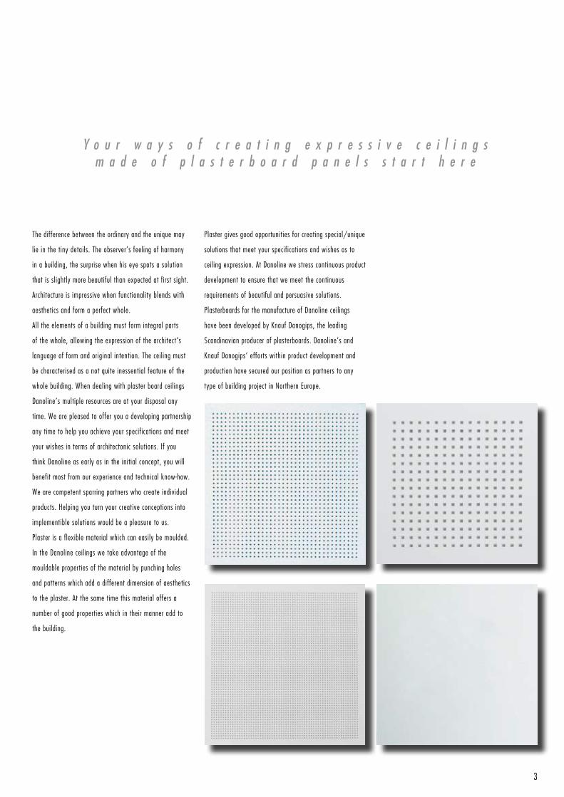
Plaster is a flexible material which can easily be moulded.
In the Danoline ceilings we take advantage of the
mouldable properties of the material by punching holes
and patterns which add a different dimension of aesthetics
to the plaster. At the same time this material offers a
number of good properties which in their manner add to
the building.
Y o u r w a y s o f c r e a t i n g e x p r e s s i v e c e i l i n g sm a d e o f p l a s t e r b o a r d p a n e l s s t a r t h e r e
Plaster gives good opportunities for creating special/unique
solutions that meet your specifications and wishes as to
ceiling expression. At Danoline we stress continuous product
development to ensure that we meet the continuous
requirements of beautiful and persuasive solutions.
Plasterboards for the manufacture of Danoline ceilings
have been developed by Knauf Danogips, the leading
Scandinavian producer of plasterboards. Danoline’s and
Knauf Danogips’ efforts within product development and
production have secured our position as partners to any
type of building project in Northern Europe.
3
4
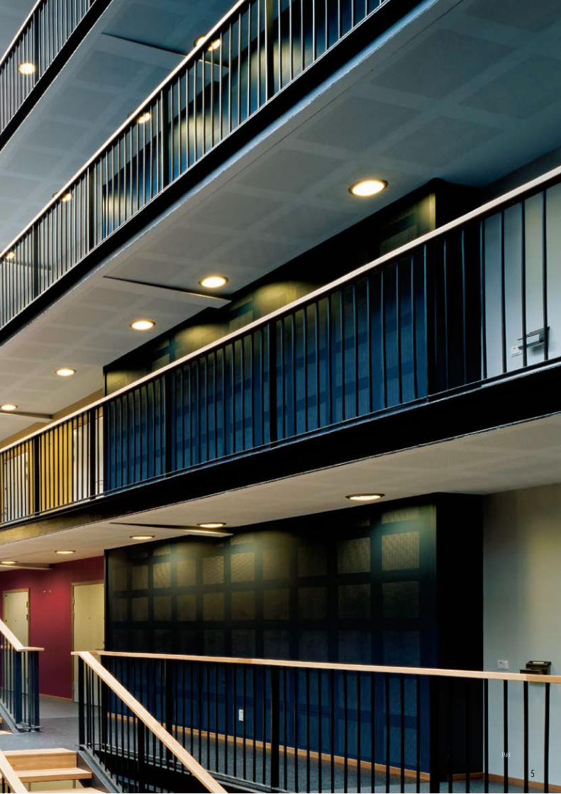
5
1165
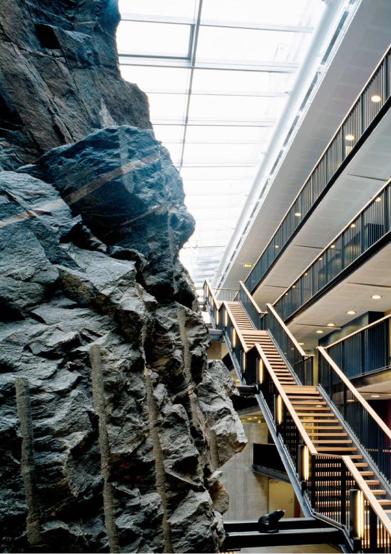
1165:
Architect: Semren Arkitektkontor, Göteborg
Project: Ungdoms bolig, Göteborg - Sweden
Product: Designpanel 1200
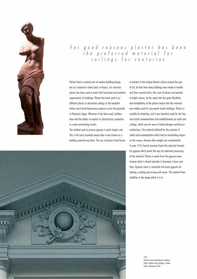
F o r g o o d r e a s o n s p l a s t e r h a s b e e nt h e p r e f e r r e d m a t e r i a l f o r
c e i l i n g s f o r c e n t u r i e s
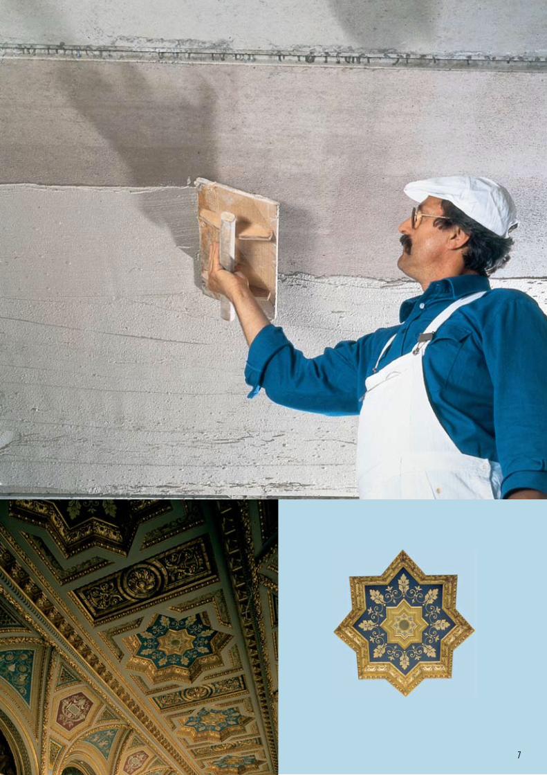
Plaster forms a natural part of modern building design,
but as a material it dates back in history. For centuries
plaster has been used to meet both functional and aesthetic
requirements of buildings. Plaster has been used in as
different places as decorative ceilings in the beautiful
Italian and French Renaissance palaces as for the pyramids
in Pharaonic Egypt. Wherever it has been used, builders
have had the ability to exploit its characteristic properties
to create outstanding results.
The method used to process gypsum is quite simple, and
this is the most essential reason why it was known as a
building material way back. The use of plaster found favour
in earnest in the antique Roman culture around the year
0 A.D. At that time many buildings were made in marble
and then covered with a thin coat of plaster and painted
in bright colours. At the same time the great flexibility
and mouldability of the plaster meant that this material
was widely used for stuccowork inside buildings. Plaster is
suitable for detailing, and it was therefore used for the fine
and artistic ornamentation and embellishments on walls and
ceilings, which may be seen in Italian Baroque and Rococo
architecture. This material allowed for the creation of
reliefs and ornamentation which had an outstanding impact
on the rooms, whereas their weight was unsubstantial.
In year 1775 French Lavoisier found the chemical formula
for gypsum which paved the way for industrial processing
of the material. Plaster is made from the gypsum stone
mineral which is found naturally in Germany, France and
Italy. Gypsum stone is converted into burnt gypsum via
heating, crushing and mixing with water. The material then
solidifies in the shape which it is in.
6
7
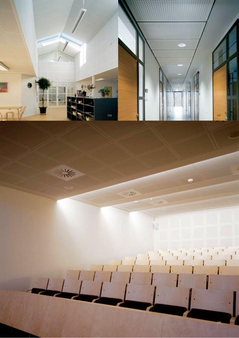
1290
1276 1157
8
1276:
Architect: Erik Eriksen, Gørløse
Project: Daginstition, Maglekærvej, Gørløse - Denmark
Product: Danopanel - G1, R
1157:
Architect: MA Arkitekter, Borås
Project: Högskolan i Borås- Sweden
Product: Corridor Swing 600 - Q1
1290:
Architect: S og I arkitekter
Project: OBH Gruppen, Odense - Denmark
Product: Contur 600 - M1 , Designpanel 900 - M1F
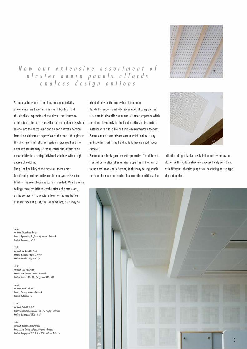
1287:
Architect: Hune & Elkjær
Project: Korsvang, Assens - Denmark
Product: Tectopanel - G1
1284:
Architect: Rudolf Lolk A/S
Project: Arkitektfirmaet Rudolf Lolk A/S, Esbjerg - Denmark
Product: Designpanel 1200 - M1F
1137:
Architect: Wingård Arkitekt kontor
Project: Astra Zeneca tnghuset, Göteborg - Sweden
Product: Designpanel 900 M1F / 1200 M2F and Mitex - R
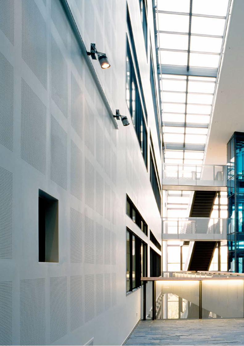
N o w o u r e x t e n s i v e a s s o r t m e n t o fp l a s t e r b o a r d p a n e l s a f f o r d s
e n d l e s s d e s i g n o p t i o n s
Smooth surfaces and clean lines are characteristics
of contemporary beautiful, minimalist buildings and
the simplistic expression of the plaster contributes to
architectonic clarity. It is possible to create elements which
recede into the background and do not distract attention
from the architectonic expression of the room. With plaster
the strict and minimalist expression is preserved and the
extensive mouldability of the material also affords wide
opportunities for creating individual solutions with a high
degree of detailing.
The great flexibility of the material, means that
functionality and aesthetics can form a synthesis so the
finish of the room becomes just as intended. With Danoline
ceilings there are infinite combinations of expressions,
as the surface of the plaster allows for the application
of many types of paint, foils or punchings, so it may be
adapted fully to the expression of the room.
Beside the evident aesthetic advantages of using plaster,
this material also offers a number of other properties which
contribute favourably to the building. Gypsum is a natural
material with a long life and it is environmentally friendly.
Plaster can emit and adsorb vapour which makes it play
an important part if the building is to have a good indoor
climate.
Plaster also affords good acoustic properties. The different
types of perforation offer varying properties in the form of
sound absorption and reflection, in this way ceiling panels
can tune the room and render fine acoustic conditions. The
reflection of light is also easily influenced by the use of
plaster as the surface structure appears highly varied and
with different reflective properties, depending on the type
of paint applied.
1137
1284
1287
9

Products
1149
12
1324
13
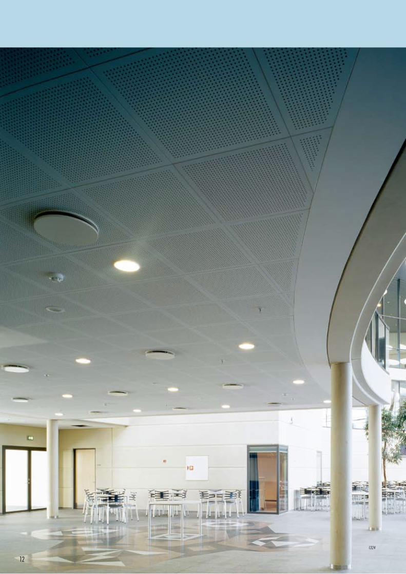
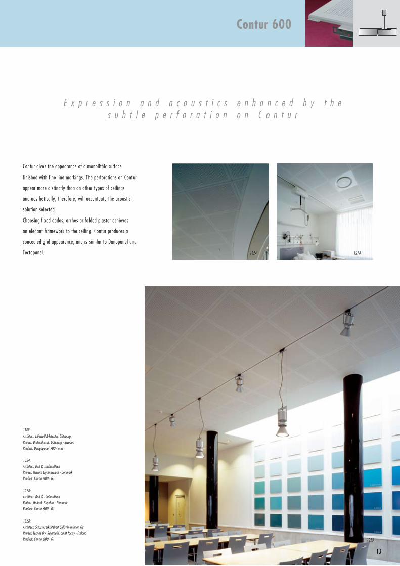
Contur gives the appearance of a monolithic surface
finished with fine line markings. The perforations on Contur
appear more distinctly than on other types of ceilings
and aesthetically, therefore, will accentuate the acoustic
solution selected.
Choosing fixed dados, arches or folded plaster achieves
an elegant framework to the ceiling. Contur produces a
concealed grid appearence, and is similar to Danopanel and
Tectopanel.
E x p r e s s i o n a n d a c o u s t i c s e n h a n c e d b y t h es u b t l e p e r f o r a t i o n o n C o n t u r
1149:
Architect: Liljewall Arkitekter, Göteborg
Project: Biotechhuset, Göteborg - Sweden
Product: Designpanel 900 - M2F
1324:
Architect: Dall & Lindhardtsen
Project: Nærum Gymnassium - Denmark
Product: Contur 600 - G1
1278:
Architect: Dall & Lindhardtsen
Project: Holbæk Sygehus - Denmark
Product: Contur 600 - G1
1223:
Architect: Sisustusarkkitehdit Gullstén-Inkinen Oy
Project: Teknos Oy, Rajamäki, paint factry - Finland
Product: Contur 600 - G1
Contur 600
1223
12781324
600Max. 600
600
Max. 600
6001200
14
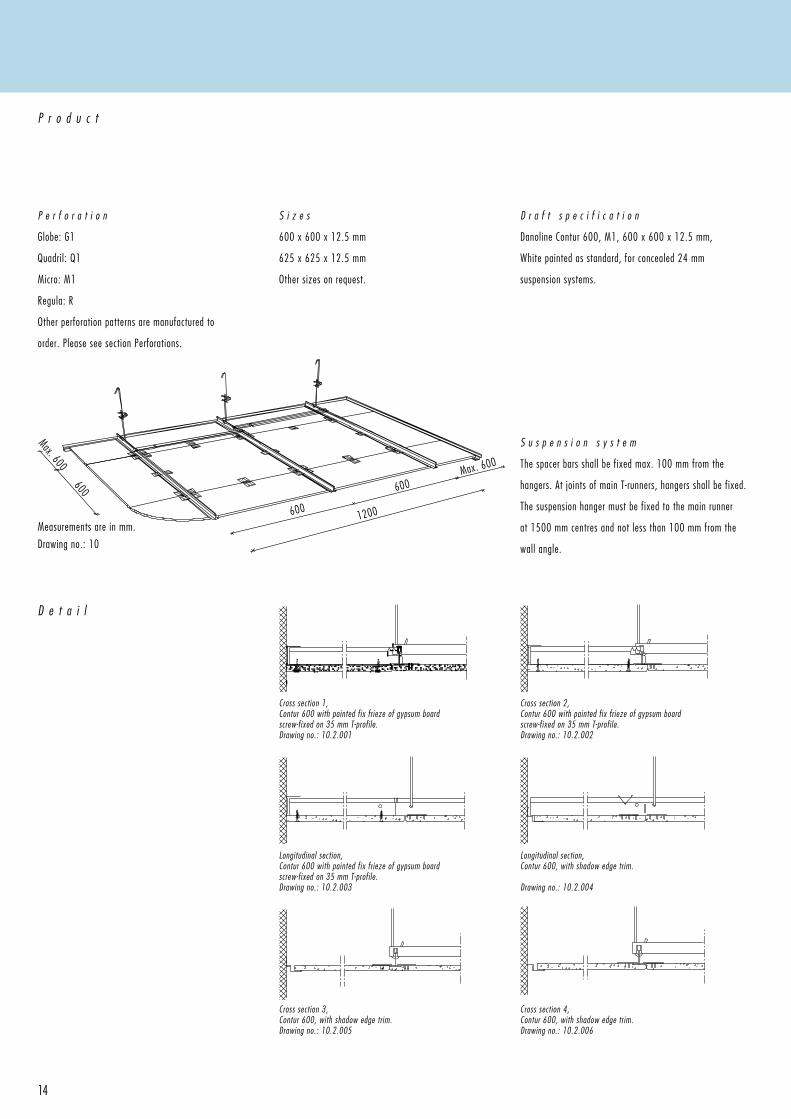
S u s p e n s i o n s y s t e m
The spacer bars shall be fixed max. 100 mm from the
hangers. At joints of main T-runners, hangers shall be fixed.
The suspension hanger must be fixed to the main runner
at 1500 mm centres and not less than 100 mm from the
wall angle.
Measurements are in mm.
Drawing no.: 10
D e t a i l
Cross section 4, Contur 600, with shadow edge trim.Drawing no.: 10.2.006
Cross section 3, Contur 600, with shadow edge trim.Drawing no.: 10.2.005
Longitudinal section, Contur 600, with shadow edge trim.
Drawing no.: 10.2.004
Longitudinal section, Contur 600 with painted fix frieze of gypsum board screw-fixed on 35 mm T-profile.Drawing no.: 10.2.003
Cross section 2, Contur 600 with painted fix frieze of gypsum board screw-fixed on 35 mm T-profile.Drawing no.: 10.2.002
Cross section 1, Contur 600 with painted fix frieze of gypsum boardscrew-fixed on 35 mm T-profile.Drawing no.: 10.2.001
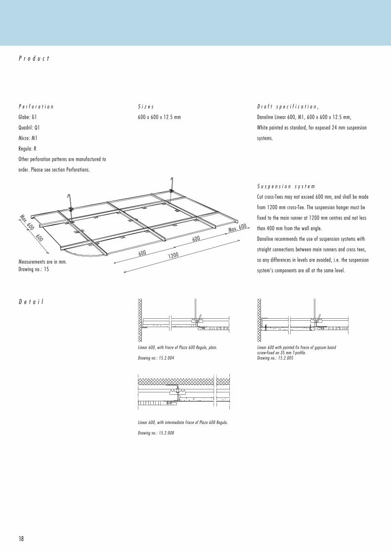
P e r f o r a t i o n
Globe: G1
Quadril: Q1
Micro: M1
Regula: R
Other perforation patterns are manufactured to
order. Please see section Perforations.
P r o d u c t
S i z e s
600 x 600 x 12.5 mm
625 x 625 x 12.5 mm
Other sizes on request.
D r a f t s p e c i f i c a t i o n
Danoline Contur 600, M1, 600 x 600 x 12.5 mm,
White painted as standard, for concealed 24 mm
suspension systems.
15
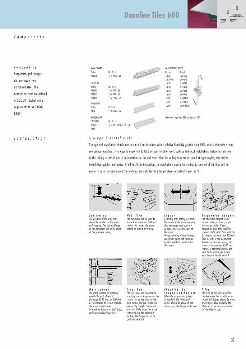
S t o r a g e & I n s t a l l a t i o n
Storage and installation should not be carried out in rooms with a relative humidity greater than 70%, unless otherwise stated,
see section Moisture . It is equally important to take account of other work such as technical installations before installation
of the ceiling is carried out. It is important for the end result that the ceiling tiles are installed at right angles, this makes
installation quicker and easier. It will facilitate inspections to installations above the ceiling as removal of the tiles will be
easier. It is not recommended that ceilings are installed at a temperature consistantly over 50°C.
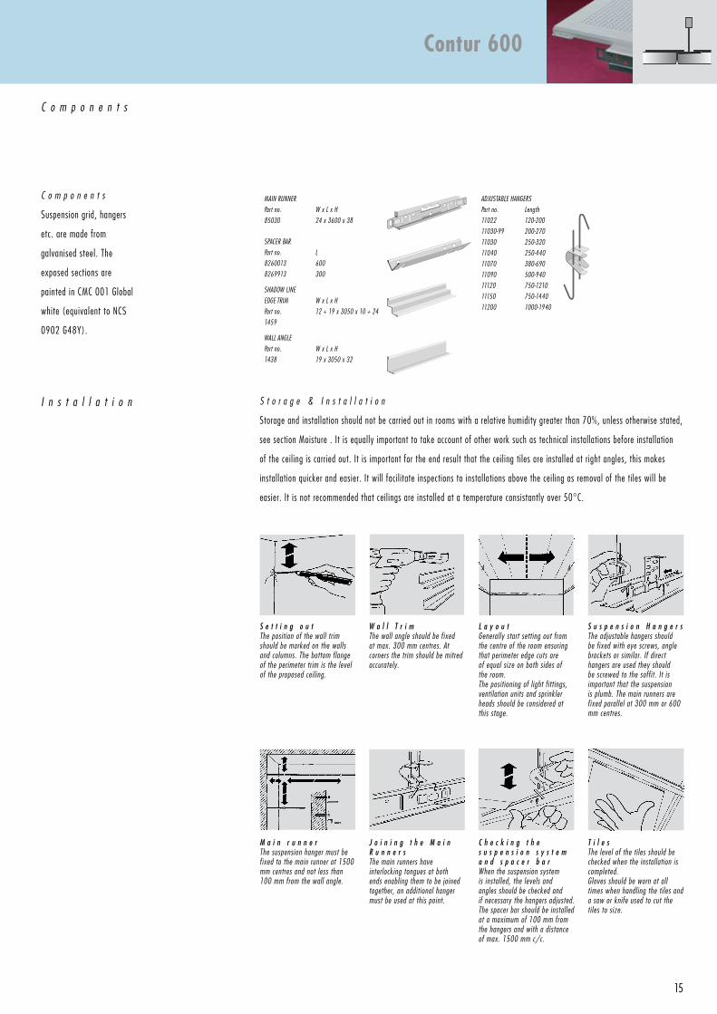
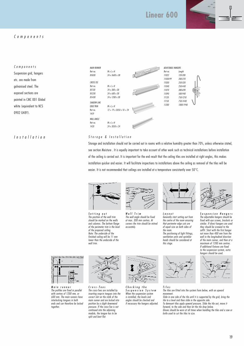
C o m p o n e n t s
MAIN RuNNeR
Part no.
85030
W x L x H
24 x 3600 x 38
ADjuSTABLe HANGeRS
Part no. Length
11022 120-200
11030-99 200-270
11030 250-320
11040 250-440
11070 380-690
11090 500-940
11120 750-1210
11150 750-1440
11200 1000-1940
SPACeR BAR
Part no.
8260013
8269913
L
600
300
SHADOW LINe
eDGe TRIM
Part no.
1459
W x L x H
12 + 19 x 3050 x 10 + 24
WALL ANGLe
Part no.
1438
W x L x H
19 x 3050 x 32
I n s t a l l a t i o n
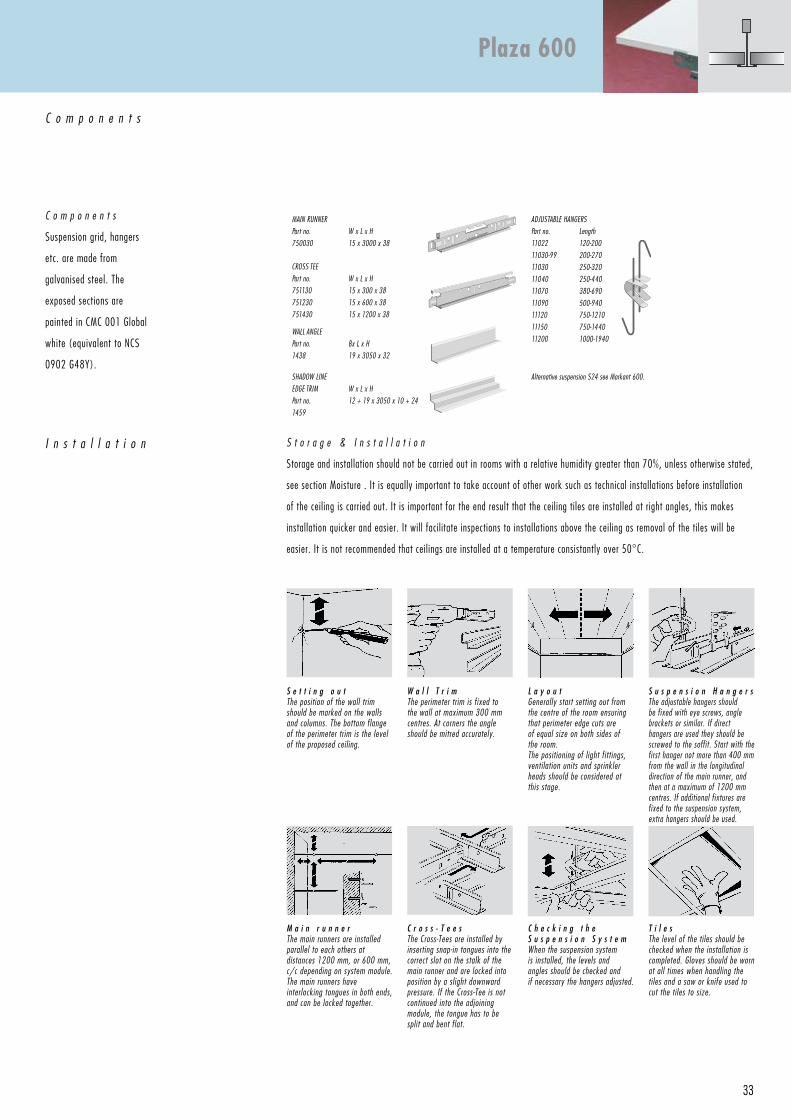
C o m p o n e n t s
Suspension grid, hangers
etc. are made from
galvanised steel. The
exposed sections are
painted in CMC 001 Global
white (equivalent to NCS
0902 G48Y).
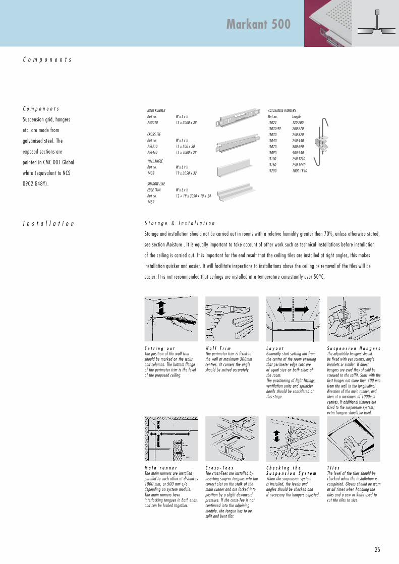
S e t t i n g o u tThe position of the wall trim should be marked on the walls and columns. The bottom flange of the perimeter trim is the level of the proposed ceiling.
S u s p e n s i o n H a n g e r sThe adjustable hangers should be fixed with eye screws, angle brackets or similar. If direct hangers are used they should be screwed to the soffit. It is important that the suspension is plumb. The main runners are fixed parallel at 300 mm or 600 mm centres.
C h e c k i n g t h e s u s p e n s i o n s y s t e m a n d s p a c e r b a rWhen the suspension system is installed, the levels and angles should be checked and if necessary the hangers adjusted. The spacer bar should be installed at a maximum of 100 mm from the hangers and with a distance of max. 1500 mm c/c.
W a l l T r i mThe wall angle should be fixed at max. 300 mm centres. At corners the trim should be mitred accurately.
M a i n r u n n e rThe suspension hanger must be fixed to the main runner at 1500 mm centres and not less than 100 mm from the wall angle.
T i l e sThe level of the tiles should be checked when the installation is completed. Gloves should be worn at all times when handling the tiles and a saw or knife used to cut the tiles to size.
L a y o u tGenerally start setting out from the centre of the room ensuring that perimeter edge cuts are of equal size on both sides of the room.The positioning of light fittings, ventilation units and sprinkler heads should be considered at this stage.
J o i n i n g t h e M a i n R u n n e r sThe main runners have interlocking tongues at both ends enabling them to be joined together, an additional hanger must be used at this point.
Contur 600
A A
16
1124
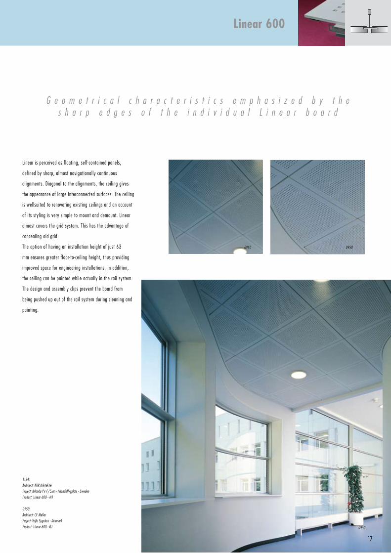
17
Linear is perceived as floating, self-contained panels,
defined by sharp, almost navigationally continuous
alignments. Diagonal to the alignments, the ceiling gives
the appearance of large interconnected surfaces. The ceiling
is wellsuited to renovating existing ceilings and on account
of its styling is very simple to mount and demount. Linear
almost covers the grid system. This has the advantage of
concealing old grid.
The option of having an installation height of just 63
mm ensures greater floor-to-ceiling height, thus providing
improved space for engineering installations. In addition,
the ceiling can be painted while actually in the rail system.
The design and assembly clips prevent the board from
being pushed up out of the rail system during cleaning and
painting.
G e o m e t r i c a l c h a r a c t e r i s t i c s e m p h a s i z e d b y t h es h a r p e d g e s o f t h e i n d i v i d u a l L i n e a r b o a r d
1124:
Architect: KHR Arkitekter
Project: Arlanda Pir F/5:an - Arlandaflygplats - Sweden
Product: Linear 600 - M1
0950:
Architect: CF Møller
Project: Vejle Sygehus - Denmark
Product: Linear 600 - G1
Linear 600
0950
09500950
600Max. 600
600
Max. 600
6001200
18
P e r f o r a t i o n
Globe: G1
Quadril: Q1
Micro: M1
Regula: R
Other perforation patterns are manufactured to
order. Please see section Perforations.
P r o d u c t
S i z e s
600 x 600 x 12.5 mm
D r a f t s p e c i f i c a t i o n ,
Danoline Linear 600, M1, 600 x 600 x 12.5 mm,
White painted as standard, for exposed 24 mm suspension
systems.
S u s p e n s i o n s y s t e m
Cut cross-Tees may not exceed 600 mm, and shall be made
from 1200 mm cross-Tee. The suspension hanger must be
fixed to the main runner at 1200 mm centres and not less
than 400 mm from the wall angle.
Danoline recommends the use of suspension systems with
straight connections between main runners and cross tees,
so any differences in levels are avoided, i.e. the suspension
system’s components are all at the same level.
Measurements are in mm.Drawing no.: 15
D e t a i l
Linear 600, with frieze of Plaza 600 Regula, plain.
Drawing no.: 15.2.004
Linear 600 with painted fix frieze of gypsum board screw-fixed on 35 mm T-profile.Drawing no.: 15.2.005
Linear 600, with intermediate frieze of Plaza 600 Regula.
Drawing no.: 15.2.008
19
C o m p o n e n t s
I n s t a l l a t i o n
MAIN RuNNeR
Part no.
85030
W x L x H
24 x 3600 x 38
ADjuSTABLe HANGeRS
Part no. Length
11022 120-200
11030-99 200-270
11030 250-320
11040 250-440
11070 380-690
11090 500-940
11120 750-1210
11150 750-1440
11200 1000-1940
CROSS Tee
Part no.
85130
85230
85430
W x L x H
24 x 300 x 38
24 x 600 x 38
24 x 1200 x 38
SHADOW LINe
eDGe TRIM
Part no.
1459
W x L x H
12 + 19 x 3050 x 10 + 24
WALL ANGLe
Part no.
1420
W x L x H
24 x 3050 x 24
C o m p o n e n t s
Suspension grid, hangers
etc. are made from
galvanised steel. The
exposed sections are
painted in CMC 001 Global
white (equivalent to NCS
0902 G48Y).
S t o r a g e & I n s t a l l a t i o n
Storage and installation should not be carried out in rooms with a relative humidity greater than 70%, unless otherwise stated,
see section Moisture . It is equally important to take account of other work such as technical installations before installation
of the ceiling is carried out. It is important for the end result that the ceiling tiles are installed at right angles, this makes
installation quicker and easier. It will facilitate inspections to installations above the ceiling as removal of the tiles will be
easier. It is not recommended that ceilings are installed at a temperature consistantly over 50°C.
L a y o u tGenerally start setting out from the centre of the room ensuring that perimeter edge cuts are of equal size on both sides of the room.The positioning of light fittings, ventilation units and sprinkler heads should be considered at this stage.
W a l l T r i mThe wall angle should be fixed at max. 300 mm centres. At corners the trim should be mitred accurately.
S e t t i n g o u tThe position of the wall trim should be marked on the walls and columns. The bottom flange of the perimeter trim is the level of the proposed ceiling.Note: The underside of the finished ceiling will be 11 mm lower than the underside of the wall trim.
S u s p e n s i o n H a n g e r sThe adjustable hangers should be fixed with eye screws, brackets or similar. If direct hangers are used they should be screwed to the soffit. Start with the first hanger not more than 400 mm from the wall in the longitudinal direction of the main runner, and then at a maximum of 1200 mm centres. If additional fixtures are fixed to the suspension system, extra hangers should be used.
M a i n r u n n e rThe profiles are fixed in parallel with centres of 1200 mm, or 600 mm. The main runners have interlocking tongues in both ends and can therefore be locked together.
C r o s s - T e e sThe cross-Tees are installed by inserting snap-in tongues into the correct slot on the stalk of the main runner and are locked into position by a slight downward pressure. If the cross-Tee is not continued into the adjoining module, the tongue has to be split and bent flat.
C h e c k i n g t h e S u s p e n s i o n S y s t e mWhen the suspension system is installed, the levels and angles should be checked and if necessary the hangers adjusted.
T i l e sThe tiles are fitted into the system from below, with an upward movement.Slide in one side of the tile until it is supported by the grid, bring the tile to a level and then slide in the opposite side. To demount tiles apply upward pressure. Slide the tile out, move it forward, to the side and then let the tile drop below.Gloves should be worn at all times when handling the tiles and a saw or knife used to cut the tiles to size.
Linear 600
A A
20
1269
21
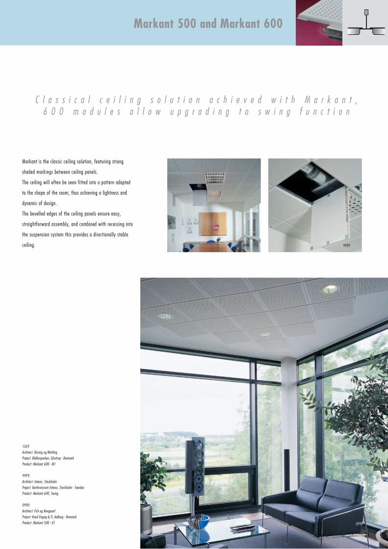
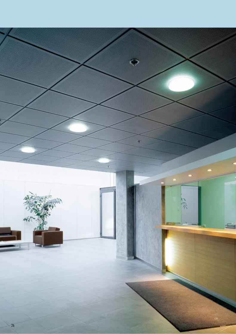
Markant is the classic ceiling solution, featuring strong
shaded markings between ceiling panels.
The ceiling will often be seen fitted into a pattern adapted
to the shape of the room, thus achieving a lightness and
dynamic of design.
The bevelled edges of the ceiling panels ensure easy,
straightforward assembly, and combined with recessing into
the suspension system this provides a directionally stable
ceiling.
C l a s s i c a l c e i l i n g s o l u t i o n a c h i e v e d w i t h M a r k a n t ,6 0 0 m o d u l e s a l l o w u p g r a d i n g t o s w i n g f u n c t i o n
1269:
Architect: Dissing og Weitling
Project: Rådhusparken, Glostrup - Denmark
Product: Markant 600 - M1
9999:
Architect: Interoc, Stockholm
Project: Konferensrum Interoc, Stockholm - Sweden
Product: Markant 600, Swing
0990:
Architect: Fich og Bengaard
Project: Knud engsig A/S, Aalborg - Denmark
Product: Markant 500 - G1
Markant 500 and Markant 600
0990
99999999
600Max. 600
600
Max. 600
6001200
22
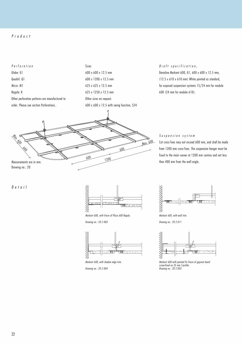
P e r f o r a t i o n
Globe: G1
Quadril: Q1
Micro: M1
Regula: R
Other perforation patterns are manufactured to
order. Please see section Perforations..
P r o d u c t
Sizes
600 x 600 x 12.5 mm
600 x 1200 x 12.5 mm
625 x 625 x 12.5 mm
625 x 1250 x 12.5 mm
Other sizes on request.
600 x 600 x 12.5 with swing function, S24
D r a f t s p e c i f i c a t i o n ,
Danoline Markant 600, G1, 600 x 600 x 12.5 mm,
(12.5 x 610 x 610 mm) White painted as standard,
for exposed suspension systems 15/24 mm for module
600 (24 mm for module 610).
S u s p e n s i o n s y s t e m
Cut cross-Tees may not exceed 600 mm, and shall be made
from 1200 mm cross-Tees. The suspension hanger must be
fixed to the main runner at 1200 mm centres and not less
than 400 mm from the wall angle.Measurements are in mm.
Drawing no.: 20
D e t a i l
Markant 600, with frieze of Plaza 600 Regula.
Drawing no.: 20.2.003
Markant 600, with wall trim.
Drawing no.: 20.2.011
Markant 600, with shadow edge trim.
Drawing no.: 20.2.004
Markant 600 with painted fix frieze of gypsum board screw-fixed on 35 mm T-profile.Drawing no.: 20.2.002

23
C o m p o n e n t s
I n s t a l l a t i o n
MAIN RuNNeR
Part no.
85030
W x L x H
24 x 3600 x 38
MAIN RuNNeR
Part no.
750030
W x L x H
15 x 3000 x 38
ADjuSTABLe HANGeRS
Part no. Length
11022 120-200
11030-99 200-270
11030 250-320
11040 250-440
11070 380-690
11090 500-940
11120 750-1210
11150 750-1440
11200 1000-1940
CROSS Tee
Part no.
85130
85230
85430
W x L x H
24 x 300 x 38
24 x 600 x 38
24 x 1200 x 38
CROSS Tee
Part no.
751130
751230
751430
W x L x H
15 x 300 x 38
15 x 600 x 38
15 x 1200 x 38
WALL ANGLe
Part no.
1420
W x L x H
24 x 3050 x 24
WALL ANGLe
Part no.
1438
W x L x H
19 x 3050 x 32
SHADOW LINe
eDGe TRIM
Part no.
1459
W x L x H
10 + 24 x 3050 x 12 + 19
C o m p o n e n t s
Suspension grid, hangers
etc. are made from
galvanised steel. The
exposed sections are
painted in CMC 001 Global
white (equivalent to NCS
0902 G48Y).
S t o r a g e & I n s t a l l a t i o n
Storage and installation should not be carried out in rooms with a relative humidity greater than 70%, unless otherwise stated,
see section Moisture . It is equally important to take account of other work such as technical installations before installation
of the ceiling is carried out. It is important for the end result that the ceiling tiles are installed at right angles, this makes
installation quicker and easier. It will facilitate inspections to installations above the ceiling as removal of the tiles will be
easier. It is not recommended that ceilings are installed at a temperature consistantly over 50°C.
L a y o u tGenerally start setting out from the centre of the room ensuring that perimeter edge cuts are of equal size on both sides of the room.The positioning of light fittings, ventilation units and sprinkler heads should be considered at this stage.
W a l l T r i mThe perimeter trim is fixed to the wall at maximum 300 mm centres. At corners the angle should be mitred accurately.
S e t t i n g o u tThe position of the wall trim should be marked on the walls and columns. The bottom flange of the perimeter trim is the level of the proposed ceiling.
S u s p e n s i o n H a n g e r sThe adjustable hangers should be fixed with eye screws, angle brackets or similar. If direct hangers are used they should be screwed to the soffit. Start with the first hanger not more than 400 mm from the wall in the longitudinal direction of the main runner, and then at a maximum of 1200 mm centres. If additional fixtures are fixed to the suspension system, extra hangers should be used.
C r o s s - T e e sThe cross-Tees are installed by inserting snap-in tongues into the correct slot on the stalk of the main runner and are locked into position by a slight downward pressure. If the cross-Tee is not continued into the adjoining module, the tongue has to be split and bent flat.
C h e c k i n g t h e S u s p e n s i o n S y s t e mWhen the suspension system is installed, the levels and angles should be checked and if necessary the hangers adjusted.
T i l e sThe level of the tiles should be checked when the installation is completed. Gloves should be worn at all times when handling the tiles and a saw or knife used to cut the tiles to size.
M a i n r u n n e rThe main runners are installed parallel to each other at distances 1200 mm, or 600 mm, c/c depending on system module.The main runners have interlocking tongues in both ends, and can be locked together.
Markant 600
A A
500Max. 500
500
Max. 500
5001000
24
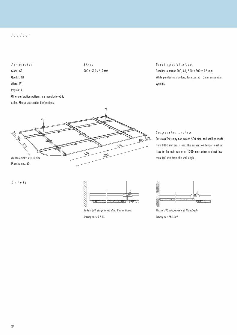
P e r f o r a t i o n
Globe: G1
Quadril: Q1
Micro: M1
Regula: R
Other perforation patterns are manufactured to
order. Please see section Perforations.
P r o d u c t
S i z e s
500 x 500 x 9.5 mm
D r a f t s p e c i f i c a t i o n ,
Danoline Markant 500, G1, 500 x 500 x 9.5 mm,
White painted as standard, for exposed 15 mm suspension
systems.
Measurements are in mm.
Drawing no.: 25
S u s p e n s i o n s y s t e m
Cut cross-Tees may not exceed 500 mm, and shall be made
from 1000 mm cross-Tees. The suspension hanger must be
fixed to the main runner at 1000 mm centres and not less
than 400 mm from the wall angle.
D e t a i l
Markant 500 with perimeter of cut Markant Regula.
Drawing no.: 25.2.001
Markant 500 with perimeter of Plaza Regula. Drawing no.: 25.2.002
25
C o m p o n e n t s
I n s t a l l a t i o n
MAIN RuNNeR
Part no.
750010
W x L x H
15 x 3000 x 38
ADjuSTABLe HANGeRS
Part no. Length
11022 120-200
11030-99 200-270
11030 250-320
11040 250-440
11070 380-690
11090 500-940
11120 750-1210
11150 750-1440
11200 1000-1940
CROSS Tee
Part no.
751210
751410
W x L x H
15 x 500 x 38
15 x 1000 x 38
WALL ANGLe
Part no.
1438
W x L x H
19 x 3050 x 32
SHADOW LINe
eDGe TRIM
Part no.
1459
W x L x H
12 + 19 x 3050 x 10 + 24
C o m p o n e n t s
Suspension grid, hangers
etc. are made from
galvanised steel. The
exposed sections are
painted in CMC 001 Global
white (equivalent to NCS
0902 G48Y).
S t o r a g e & I n s t a l l a t i o n
Storage and installation should not be carried out in rooms with a relative humidity greater than 70%, unless otherwise stated,
see section Moisture . It is equally important to take account of other work such as technical installations before installation
of the ceiling is carried out. It is important for the end result that the ceiling tiles are installed at right angles, this makes
installation quicker and easier. It will facilitate inspections to installations above the ceiling as removal of the tiles will be
easier. It is not recommended that ceilings are installed at a temperature consistantly over 50°C.
L a y o u tGenerally start setting out from the centre of the room ensuring that perimeter edge cuts are of equal size on both sides of the room.The positioning of light fittings, ventilation units and sprinkler heads should be considered at this stage.
W a l l T r i mThe perimeter trim is fixed to the wall at maximum 300mm centres. At corners the angle should be mitred accurately.
S e t t i n g o u tThe position of the wall trim should be marked on the walls and columns. The bottom flange of the perimeter trim is the level of the proposed ceiling.
S u s p e n s i o n H a n g e r sThe adjustable hangers should be fixed with eye screws, angle brackets or similar. If direct hangers are used they should be screwed to the soffit. Start with the first hanger not more than 400 mm from the wall in the longitudinal direction of the main runner, and then at a maximum of 1000mm centres. If additional fixtures are fixed to the suspension system, extra hangers should be used.
C r o s s - T e e sThe cross-Tees are installed by inserting snap-in tongues into the correct slot on the stalk of the main runner and are locked into position by a slight downward pressure. If the cross-Tee is not continued into the adjoining module, the tongue has to be split and bent flat.
C h e c k i n g t h e S u s p e n s i o n S y s t e mWhen the suspension system is installed, the levels and angles should be checked and if necessary the hangers adjusted.
T i l e sThe level of the tiles should be checked when the installation is completed. Gloves should be worn at all times when handling the tiles and a saw or knife used to cut the tiles to size.
M a i n r u n n e rThe main runners are installed parallel to each other at distances 1000 mm, or 500 mm c/c depending on system module.The main runners have interlocking tongues in both ends, and can be locked together.
Markant 500
A A
26
1201
27
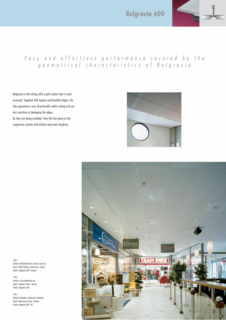
Belgravia is the ceiling with a grid system that is semi-
recessed. Supplied with tegular and bevelled edges, the
tiles guarantee a very directionally stable ceiling and are
less sensitive to damaging the edges.
As they are being installed, they fall into place in the
suspension system with distinct ease and simplicity.
E a s y a n d e f f o r t l e s s p e r f o r m a n c e s e c u r e d b y t h eg e o m e t r i c a l c h a r a c t e r i s t i c s o f B e l g r a v i a
1201:
Architect: Arkkitehtitoimisto Larkas & Laine Oy
Project: Office Building, Outokumpu - Finland
Product: Belgravia 600 - Stardust
1198:
Architect: Suunnittelukeskus Oy
Project: Hospital, Kerava - Finland
Product: Belgravia 600
1131:
Architect: Arkitekten i Vätterstad, jönköping
Project: Åhlenshuset, Borås - Sweden
Product: Belgravia 600 - M1
Belgravia 600
1131
1198
600Max. 600
600
Max. 600
6001200
28
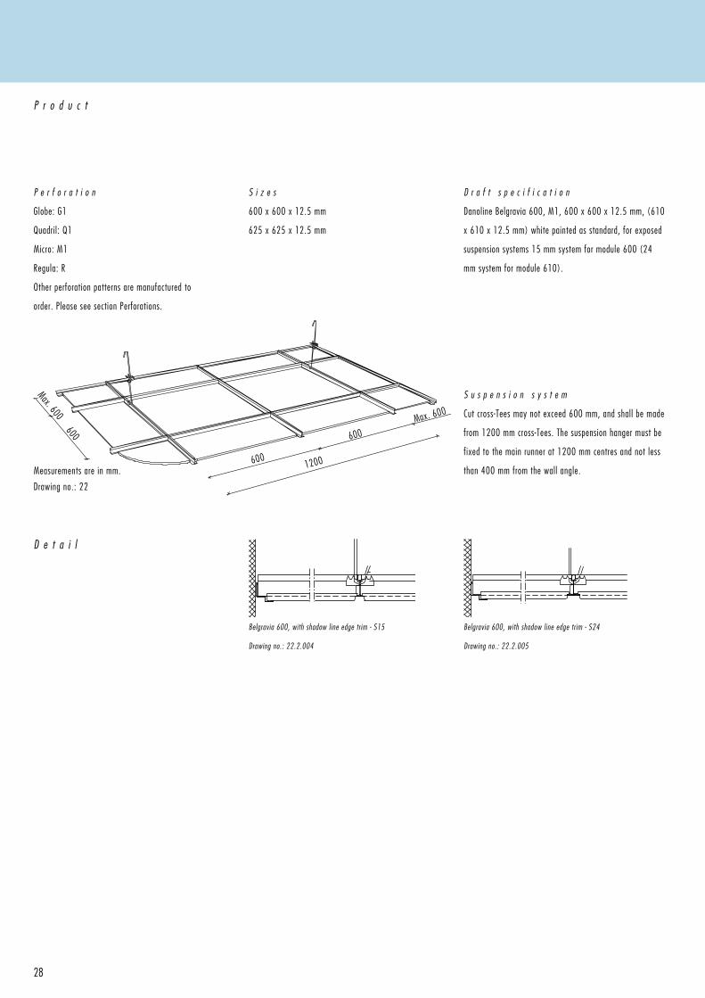
P e r f o r a t i o n
Globe: G1
Quadril: Q1
Micro: M1
Regula: R
Other perforation patterns are manufactured to
order. Please see section Perforations.
P r o d u c t
S i z e s
600 x 600 x 12.5 mm
625 x 625 x 12.5 mm
D r a f t s p e c i f i c a t i o n
Danoline Belgravia 600, M1, 600 x 600 x 12.5 mm, (610
x 610 x 12.5 mm) white painted as standard, for exposed
suspension systems 15 mm system for module 600 (24
mm system for module 610).
S u s p e n s i o n s y s t e m
Cut cross-Tees may not exceed 600 mm, and shall be made
from 1200 mm cross-Tees. The suspension hanger must be
fixed to the main runner at 1200 mm centres and not less
than 400 mm from the wall angle.
D e t a i l
Belgravia 600, with shadow line edge trim - S15
Drawing no.: 22.2.004
Belgravia 600, with shadow line edge trim - S24
Drawing no.: 22.2.005
Measurements are in mm.
Drawing no.: 22
29
C o m p o n e n t s
I n s t a l l a t i o n
MAIN RuNNeR
Part no.
750030
W x L x H
15 x 3000 x 38
MAIN RuNNeR
Part no.
85030
W x L x H
24 x 3600 x 38
ADjuSTABLe HANGeRS
Part no. Length
11022 120-200
11030-99 200-270
11030 250-320
11040 250-440
11070 380-690
11090 500-940
11120 750-1210
11150 750-1440
11200 1000-1940
CROSS Tee
Part no.
751130
751230
751430
W x L x H
15 x 300 x 38
15 x 600 x 38
15 x 1200 x 38
CROSS Tee
Part no.
85130
85230
85430
W x L x H
24 x 300 x 38
24 x 600 x 38
24 x 1200 x 38
WALL ANGLe
Part no.
1438
Bx L x H
19 x 3050 x 32
WALL ANGLe
Part no.
1420
Bx L x H
24 x 3050 x 24
SHADOW LINe
eDGe TRIM
Part no.
1466
W x L x H
15 + 15 x 3050 x 8 + 25
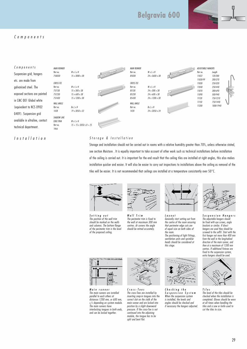
C o m p o n e n t s
Suspension grid, hangers
etc. are made from
galvanised steel. The
exposed sections are painted
in CMC 001 Global white
(equivalent to NCS 0902
G48Y). Suspension grid
available in ultraline, contact
technical department.
S t o r a g e & I n s t a l l a t i o n
Storage and installation should not be carried out in rooms with a relative humidity greater than 70%, unless otherwise stated,
see section Moisture . It is equally important to take account of other work such as technical installations before installation
of the ceiling is carried out. It is important for the end result that the ceiling tiles are installed at right angles, this also makes
installation quicker and easier. It will also be easier to carry out inspections to installations above the ceiling as removal of the
tiles will be easier. It is not recommended that ceilings are installed at a temperature consistantly over 50°C.
L a y o u tGenerally start setting out from the centre of the room ensuring that perimeter edge cuts are of equal size on both sides of the room.The positioning of light fittings, ventilation units and sprinkler heads should be considered at this stage.
W a l l T r i mThe perimeter trim is fixed to the wall at maximum 300 mm centres. At corners the angle should be mitred accurately.
S e t t i n g o u tThe position of the wall trim should be marked on the walls and columns. The bottom flange of the perimeter trim is the level of the proposed ceiling.
S u s p e n s i o n H a n g e r sThe adjustable hangers should be fixed with eye screws, angle brackets or similar. If direct hangers are used they should be screwed to the soffit. Start with the first hanger not more than 400 mm from the wall in the longitudinal direction of the main runner, and then at a maximum of 1200 mm centres. If additional fixtures are fixed to the suspension system, extra hangers should be used.
C r o s s - T e e sThe cross-Tees are installed by inserting snap-in tongues into the correct slot on the stalk of the main runner and are locked into position by a slight downward pressure. If the cross-Tee is not continued into the adjoining module, the tongue has to be split and bent flat.
C h e c k i n g t h e S u s p e n s i o n S y s t e mWhen the suspension system is installed, the levels and angles should be checked and if necessary the hangers adjusted.
T i l e sThe level of the tiles should be checked when the installation is completed. Gloves should be worn at all times when handling the tiles and a saw or knife used to cut the tiles to size.
M a i n r u n n e rThe main runners are installed parallel to each others at distances 1200 mm, or 600 mm, c/c depending on system module.The main runners have interlocking tongues in both ends, and can be locked together.
Belgravia 600
A A
30
1317
31
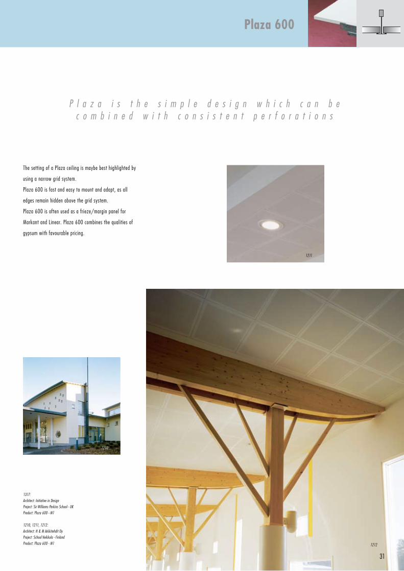
The setting of a Plaza ceiling is maybe best highlighted by
using a narrow grid system.
Plaza 600 is fast and easy to mount and adapt, as all
edges remain hidden above the grid system.
Plaza 600 is often used as a frieze/margin panel for
Markant and Linear. Plaza 600 combines the qualities of
gypsum with favourable pricing.
P l a z a i s t h e s i m p l e d e s i g n w h i c h c a n b e c o m b i n e d w i t h c o n s i s t e n t p e r f o r a t i o n s
1317:
Architect: Initiative in Design
Project: Sir Williams Perkins School - uK
Product: Plaza 600 - M1
1210, 1211, 1212:
Architect: H & M Arkkitehdit Oy
Project: School Veikkola - Finland
Product: Plaza 600 - M1
Plaza 600
1212
1210
1211
600Max. 600
600
Max. 600
6001200
32
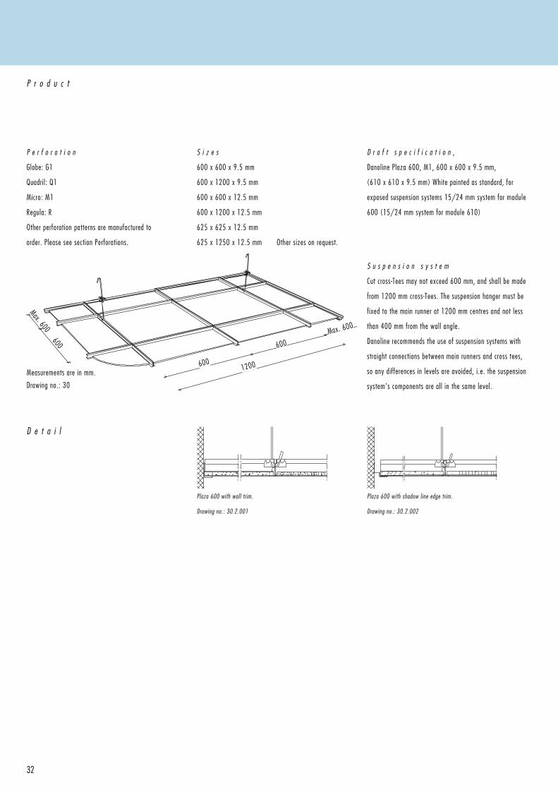
P e r f o r a t i o n
Globe: G1
Quadril: Q1
Micro: M1
Regula: R
Other perforation patterns are manufactured to
order. Please see section Perforations.
P r o d u c t
S i z e s
600 x 600 x 9.5 mm
600 x 1200 x 9.5 mm
600 x 600 x 12.5 mm
600 x 1200 x 12.5 mm
625 x 625 x 12.5 mm
625 x 1250 x 12.5 mm Other sizes on request.
D r a f t s p e c i f i c a t i o n ,
Danoline Plaza 600, M1, 600 x 600 x 9.5 mm,
(610 x 610 x 9.5 mm) White painted as standard, for
exposed suspension systems 15/24 mm system for module
600 (15/24 mm system for module 610)
Measurements are in mm.
Drawing no.: 30
D e t a i l
S u s p e n s i o n s y s t e m
Cut cross-Tees may not exceed 600 mm, and shall be made
from 1200 mm cross-Tees. The suspension hanger must be
fixed to the main runner at 1200 mm centres and not less
than 400 mm from the wall angle.
Danoline recommends the use of suspension systems with
straight connections between main runners and cross tees,
so any differences in levels are avoided, i.e. the suspension
system’s components are all in the same level.
Plaza 600 with wall trim.
Drawing no.: 30.2.001
Plaza 600 with shadow line edge trim.
Drawing no.: 30.2.002
33
C o m p o n e n t s
I n s t a l l a t i o n
MAIN RuNNeR
Part no.
750030
W x L x H
15 x 3000 x 38
ADjuSTABLe HANGeRS
Part no. Length
11022 120-200
11030-99 200-270
11030 250-320
11040 250-440
11070 380-690
11090 500-940
11120 750-1210
11150 750-1440
11200 1000-1940
CROSS Tee
Part no.
751130
751230
751430
W x L x H
15 x 300 x 38
15 x 600 x 38
15 x 1200 x 38
WALL ANGLe
Part no.
1438
Bx L x H
19 x 3050 x 32
SHADOW LINe
eDGe TRIM
Part no.
1459
W x L x H
12 + 19 x 3050 x 10 + 24
Alternative suspension S24 see Markant 600.
C o m p o n e n t s
Suspension grid, hangers
etc. are made from
galvanised steel. The
exposed sections are
painted in CMC 001 Global
white (equivalent to NCS
0902 G48Y).
S t o r a g e & I n s t a l l a t i o n
Storage and installation should not be carried out in rooms with a relative humidity greater than 70%, unless otherwise stated,
see section Moisture . It is equally important to take account of other work such as technical installations before installation
of the ceiling is carried out. It is important for the end result that the ceiling tiles are installed at right angles, this makes
installation quicker and easier. It will facilitate inspections to installations above the ceiling as removal of the tiles will be
easier. It is not recommended that ceilings are installed at a temperature consistantly over 50°C.
L a y o u tGenerally start setting out from the centre of the room ensuring that perimeter edge cuts are of equal size on both sides of the room.The positioning of light fittings, ventilation units and sprinkler heads should be considered at this stage.
W a l l T r i mThe perimeter trim is fixed to the wall at maximum 300 mm centres. At corners the angle should be mitred accurately.
S e t t i n g o u tThe position of the wall trim should be marked on the walls and columns. The bottom flange of the perimeter trim is the level of the proposed ceiling.
S u s p e n s i o n H a n g e r sThe adjustable hangers should be fixed with eye screws, angle brackets or similar. If direct hangers are used they should be screwed to the soffit. Start with the first hanger not more than 400 mm from the wall in the longitudinal direction of the main runner, and then at a maximum of 1200 mm centres. If additional fixtures are fixed to the suspension system, extra hangers should be used.
C r o s s - T e e sThe Cross-Tees are installed by inserting snap-in tongues into the correct slot on the stalk of the main runner and are locked into position by a slight downward pressure. If the Cross-Tee is not continued into the adjoining module, the tongue has to be split and bent flat.
C h e c k i n g t h e S u s p e n s i o n S y s t e mWhen the suspension system is installed, the levels and angles should be checked and if necessary the hangers adjusted.
T i l e sThe level of the tiles should be checked when the installation is completed. Gloves should be worn at all times when handling the tiles and a saw or knife used to cut the tiles to size.
M a i n r u n n e rThe main runners are installed parallel to each others at distances 1200 mm, or 600 mm, c/c depending on system module.The main runners have interlocking tongues in both ends, and can be locked together.
Plaza 600
A A
34
1300
1306 1321
35
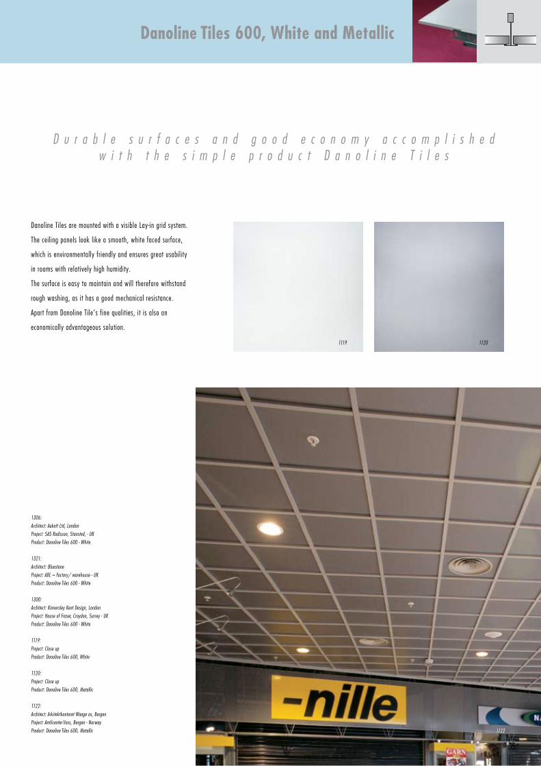
Danoline Tiles are mounted with a visible Lay-in grid system.
The ceiling panels look like a smooth, white faced surface,
which is environmentally friendly and ensures great usability
in rooms with relatively high humidity.
The surface is easy to maintain and will therefore withstand
rough washing, as it has a good mechanical resistance.
Apart from Danoline Tile’s fine qualities, it is also an
economically advantageous solution.
D u r a b l e s u r f a c e s a n d g o o d e c o n o m y a c c o m p l i s h e dw i t h t h e s i m p l e p r o d u c t D a n o l i n e T i l e s
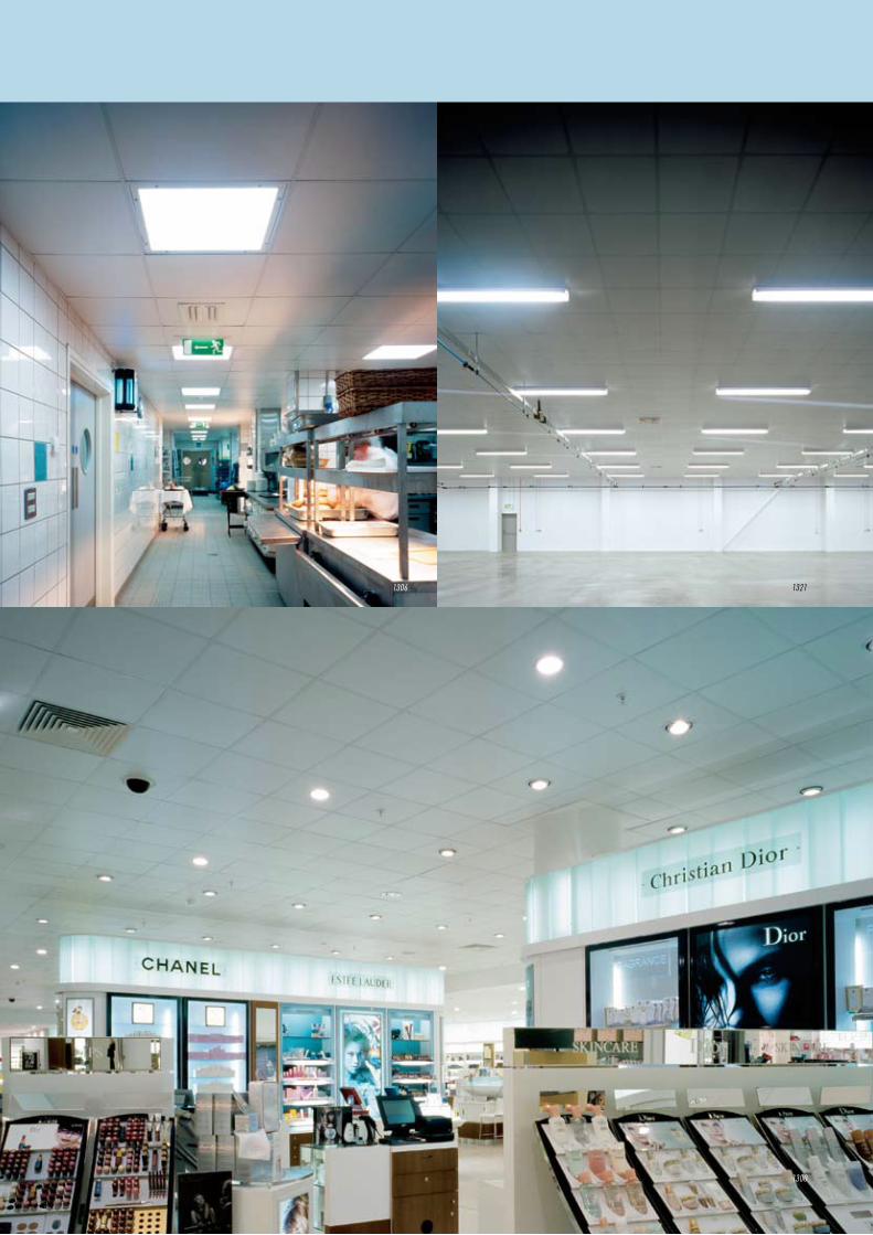
1306:
Architect: Aukett Ltd, London
Project: SAS Radisson, Stansted, - uK
Product: Danoline Tiles 600 - White
1321:
Architect: Bluestone
Project: ABL – Factory/ warehouse - uK
Product: Danoline Tiles 600 - White
1300:
Architect: Kinnersley Kent Design, London
Project: House of Fraser, Croydon, Surrey - uK
Product: Danoline Tiles 600 - White
1119:
Project: Close up
Product: Danoline Tiles 600, White
1120:
Project: Close up
Product: Danoline Tiles 600, Metallic
1122:
Architect: Arkitektkontoret Waage as, Bergen
Project: Amficenter Voss, Bergen - Norway
Product: Danoline Tiles 600, Metallic
Danoline Tiles 600, White and Metallic
1122
11201119
36
1109
37
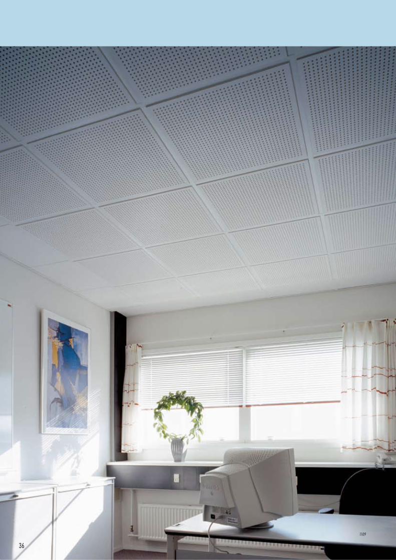
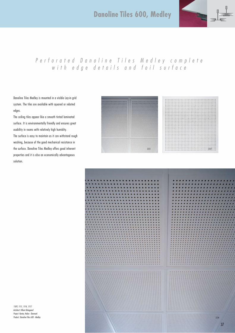
Danoline Tiles Medley is mounted in a visible Lay-in grid
system. The tiles are available with squared or rebated
edges.
The ceiling tiles appear like a smooth tinted laminated
surface. It is environmentally friendly and ensures great
usability in rooms with relatively high humidity.
The surface is easy to maintain as it can withstand rough
washing, because of the good mechanical resistance in
the surface. Danoline Tiles Medley offers good inherent
properties and it is also an economically advantageous
solution.
P e r f o r a t e d D a n o l i n e T i l e s M e d l e y c o m p l e t ew i t h e d g e d e t a i l s a n d f o i l s u r f a c e
1109, 1111, 1114, 1117:
Architect: Villum Kirkegaard
Project: Kontor, Hobro - Denmark
Product: Danoline Tiles 600 - Medley
Danoline Tiles 600, Medley
1114
11171111
600Max. 600
600
Max. 600
6001200
38
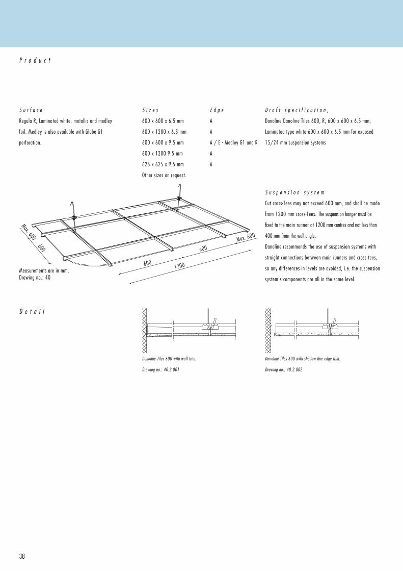
S u r f a c e
Regula R, Laminated white, metallic and medley
foil. Medley is also available with Globe G1
perforation.
P r o d u c t
S i z e s
600 x 600 x 6.5 mm
600 x 1200 x 6.5 mm
600 x 600 x 9.5 mm
600 x 1200 9.5 mm
625 x 625 x 9.5 mm
Other sizes on request.
D r a f t s p e c i f i c a t i o n ,
Danoline Danoline Tiles 600, R, 600 x 600 x 6.5 mm,
Laminated type white 600 x 600 x 6.5 mm for exposed
15/24 mm suspension systems
Measurements are in mm.Drawing no.: 40
D e t a i l
Danoline Tiles 600 with wall trim. Drawing no.: 40.2.001
Danoline Tiles 600 with shadow line edge trim.
Drawing no.: 40.2.002
S u s p e n s i o n s y s t e m
Cut cross-Tees may not exceed 600 mm, and shall be made
from 1200 mm cross-Tees. The suspension hanger must be
fixed to the main runner at 1200 mm centres and not less than
400 mm from the wall angle.
Danoline recommends the use of suspension systems with
straight connections between main runners and cross tees,
so any differences in levels are avoided, i.e. the suspension
system’s components are all in the same level.
E d g e
A
A
A / E - Medley G1 and R
A
A
39
C o m p o n e n t s
I n s t a l l a t i o n
MAIN RuNNeR
Part no.
750030
W x L x H
15 x 3000 x 38
ADjuSTABLe HANGeRS
Part no. Length
11022 120-200
11030-99 200-270
11030 250-320
11040 250-440
11070 380-690
11090 500-940
11120 750-1210
11150 750-1440
11200 1000-1940
CROSS Tee
Part no.
751130
751230
751430
W x L x H
15 x 300 x 38
15 x 600 x 38
15 x 1200 x 38
WALL ANGLe
Part no.
1438
Bx L x H
19 x 3050 x 32
SHADOW LINe
eDGe TRIM
Part no.
1459
W x L x H
12 + 19 x 3050 x 10 + 24
Alternative suspension S24 see Markant 600.
C o m p o n e n t s
Suspension grid, hangers
etc. are made from
galvanised steel. The
exposed sections are painted
in CMC 001 Global white
(equivalent to NCS 0902
G48Y).
S t o r a g e & I n s t a l l a t i o n
Storage and installation should not be carried out in rooms with a relative humidity greater than 70%, unless otherwise stated,
see section Moisture . It is equally important to take account of other work such as technical installations before installation
of the ceiling is carried out. It is important for the end result that the ceiling tiles are installed at right angles, this makes
installation quicker and easier. It will facilitate inspections to installations above the ceiling as removal of the tiles will be
easier. It is not recommended that ceilings are installed at a temperature consistantly over 50°C.
L a y o u tGenerally start setting out from the centre of the room ensuring that perimeter edge cuts are of equal size on both sides of the room.The positioning of light fittings, ventilation units and sprinkler heads should be considered at this stage.
W a l l T r i mThe perimeter trim is fixed to the wall at maximum 300 mm centres. At corners the angle should be mitred accurately.
S e t t i n g o u tThe position of the wall trim should be marked on the walls and columns. The bottom flange of the perimeter trim is the level of the proposed ceiling.
S u s p e n s i o n H a n g e r sThe adjustable hangers should be fixed with eye screws, angle brackets or similar. If direct hangers are used they should be screwed to the soffit. Start with the first hanger not more than 400 mm from the wall in the longitudinal direction of the main runner, and then at a maximum of 1200 mm centres. If additional fixtures are fixed to the suspension system, extra hangers should be used.
C r o s s - T e e sThe cross-Tees are installed by inserting snap-in tongues into the correct slot on the stalk of the main runner and are locked into position by a slight downward pressure. If the cross-Tee is not continued into the adjoining module, the tongue has to be split and bent flat.
C h e c k i n g t h e S u s p e n s i o n S y s t e mWhen the suspension system is installed, the levels and angles should be checked and if necessary the hangers adjusted.
T i l e sThe level of the tiles should be checked when the installation is completed. Gloves should be worn at all times when handling the tiles and a saw or knife used to cut the tiles to size.
M a i n r u n n e rThe main runners are installed parallel to each others at distances 1200 mm, or 600 mm, c/c depending of system module.The main runners have interlocking tongues in both ends, and can be locked together.
Danoline Tiles 600
A A
40
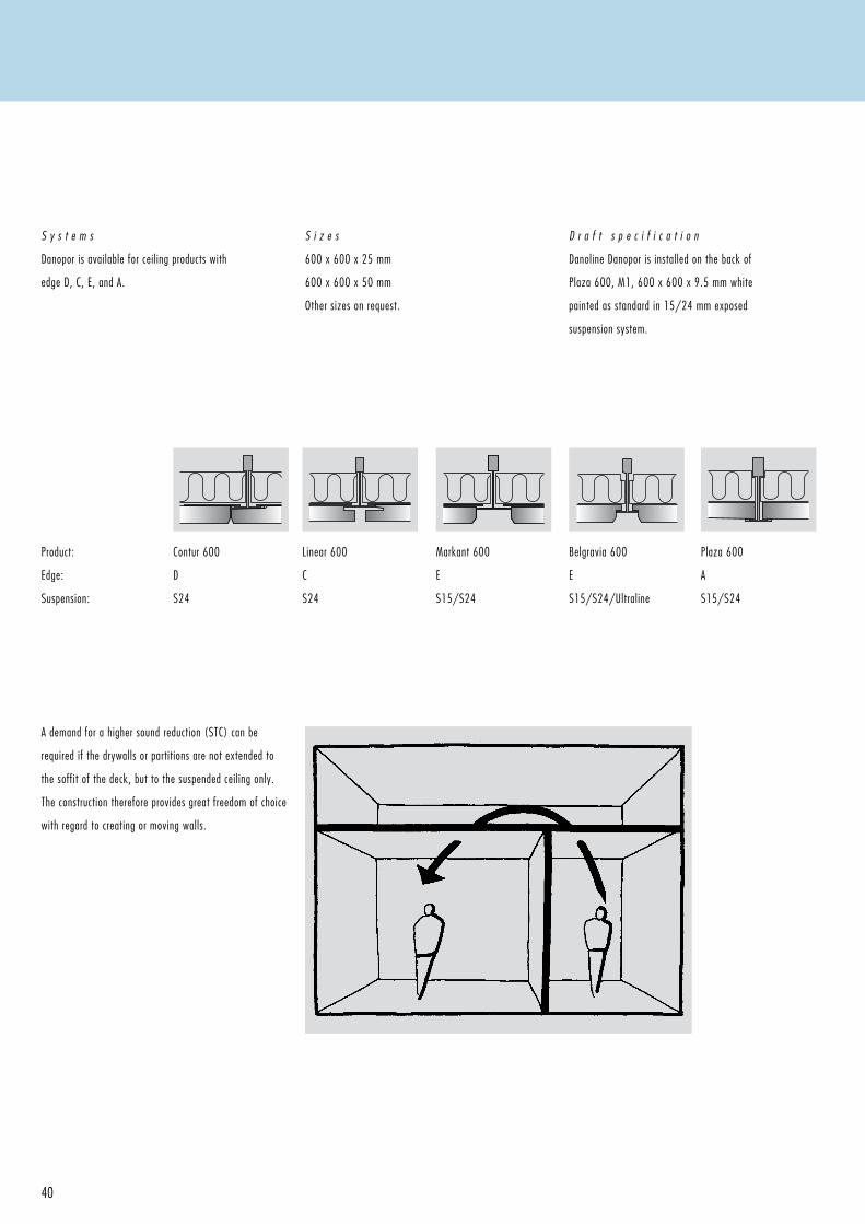
A demand for a higher sound reduction (STC) can be
required if the drywalls or partitions are not extended to
the soffit of the deck, but to the suspended ceiling only.
The construction therefore provides great freedom of choice
with regard to creating or moving walls.
S y s t e m s
Danopor is available for ceiling products with
edge D, C, E, and A.
S i z e s
600 x 600 x 25 mm
600 x 600 x 50 mm
Other sizes on request.
D r a f t s p e c i f i c a t i o n
Danoline Danopor is installed on the back of
Plaza 600, M1, 600 x 600 x 9.5 mm white
painted as standard in 15/24 mm exposed
suspension system.
Product:
Edge:
Suspension:
Contur 600
D
S24
Linear 600
C
S24
Belgravia 600
E
S15/S24/Ultraline
Markant 600
E
S15/S24
Plaza 600
A
S15/S24
41
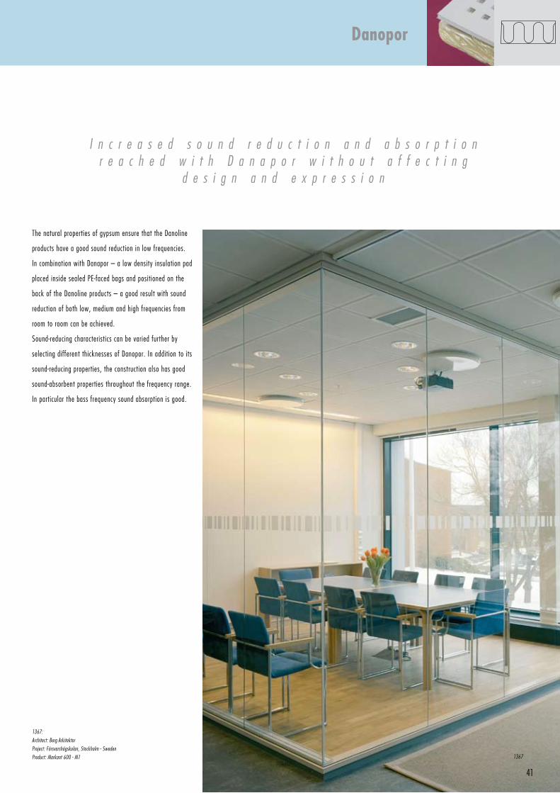
The natural properties of gypsum ensure that the Danoline
products have a good sound reduction in low frequencies.
In combination with Danapor – a low density insulation pad
placed inside sealed PE-faced bags and positioned on the
back of the Danoline products – a good result with sound
reduction of both low, medium and high frequencies from
room to room can be achieved.
Sound-reducing characteristics can be varied further by
selecting different thicknesses of Danopor. In addition to its
sound-reducing properties, the construction also has good
sound-absorbent properties throughout the frequency range.
In particular the bass frequency sound absorption is good.
I n c r e a s e d s o u n d r e d u c t i o n a n d a b s o r p t i o nr e a c h e d w i t h D a n a p o r w i t h o u t a f f e c t i n g
d e s i g n a n d e x p r e s s i o n
1367:
Architect: Berg Arkitekter
Project: Försvarshögskolan, Stockholm - Sweden
Product: Markant 600 - M1
Danopor
1367
42
1179
43
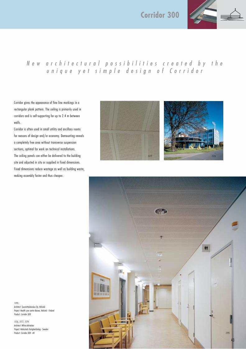
Corridor gives the appearance of fine line markings in a
rectangular plank pattern. The ceiling is primarily used in
corridors and is self-supporting for up to 2.4 m between
walls.
Corridor is often used in small util ity and ancillary rooms
for reasons of design and/or economy. Demounting reveals
a completely free area without transverse suspension
sections, optimal for work on technical installations.
The ceiling panels can either be delivered to the building
site and adjusted in situ or supplied in fixed dimensions.
Fixed dimensions reduce wastage as well as building waste,
making assembly faster and thus cheaper.
1195:
Architect: Suunnittelukeskus Oy, Helsinki
Project: Health care centre Kerava, Helsinki - Finland
Product: Corridor 300
1176, 1177, 1179:
Architect: White Arkitekter
Project: Halmstads Fastighetsbolag - Sweden
Product: Corridor 300 - M1
N e w a r c h i t e c t u r a l p o s s i b i l i t i e s c r e a t e d b y t h eu n i q u e y e t s i m p l e d e s i g n o f C o r r i d o r
Corridor 300
1195
11761177
Max. 2400
44
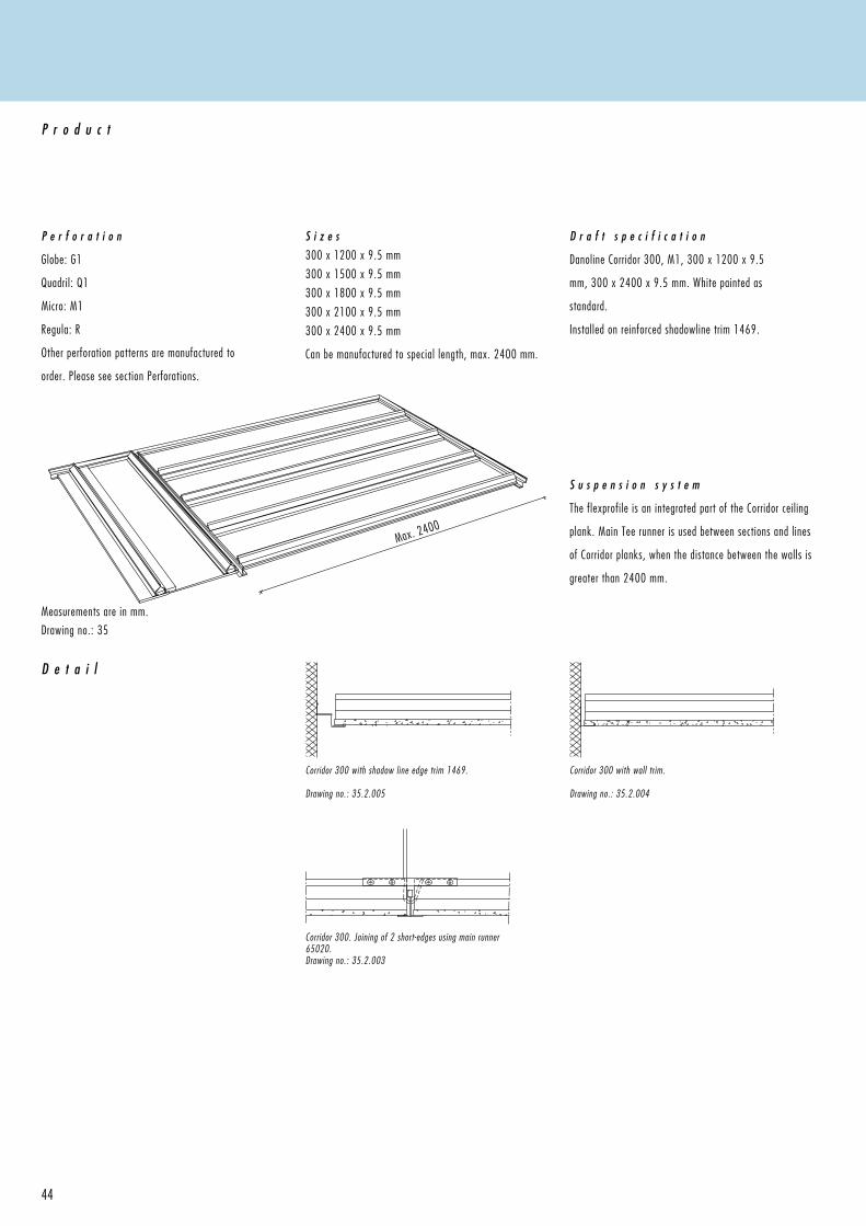
Measurements are in mm.
Drawing no.: 35
D e t a i l
P e r f o r a t i o n
Globe: G1
Quadril: Q1
Micro: M1
Regula: R
Other perforation patterns are manufactured to
order. Please see section Perforations.
P r o d u c t
S i z e s300 x 1200 x 9.5 mm
300 x 1500 x 9.5 mm
300 x 1800 x 9.5 mm
300 x 2100 x 9.5 mm
300 x 2400 x 9.5 mm
Can be manufactured to special length, max. 2400 mm.
D r a f t s p e c i f i c a t i o n
Danoline Corridor 300, M1, 300 x 1200 x 9.5
mm, 300 x 2400 x 9.5 mm. White painted as
standard.
Installed on reinforced shadowline trim 1469.
S u s p e n s i o n s y s t e m
The flexprofile is an integrated part of the Corridor ceiling
plank. Main Tee runner is used between sections and lines
of Corridor planks, when the distance between the walls is
greater than 2400 mm.
Corridor 300. Joining of 2 short-edges using main runner 65020.Drawing no.: 35.2.003
Corridor 300 with shadow line edge trim 1469.
Drawing no.: 35.2.005
Corridor 300 with wall trim. Drawing no.: 35.2.004
45
S t o r a g e & I n s t a l l a t i o n
Storage and installation should not be carried out in rooms with a relative humidity greater than 70%, unless otherwise stated,
see section Moisture . It is equally important to take account of other work such as technical installations before installation
of the ceiling is carried out. It is important for the end result that the ceiling tiles are installed at right-angles, this makes
installation quicker and easier. It will facilitate inspections to installations above the ceiling as removal of the tiles will be
easier. It is not recommended that ceilings are installed at a temperature consistantly over 50°C.
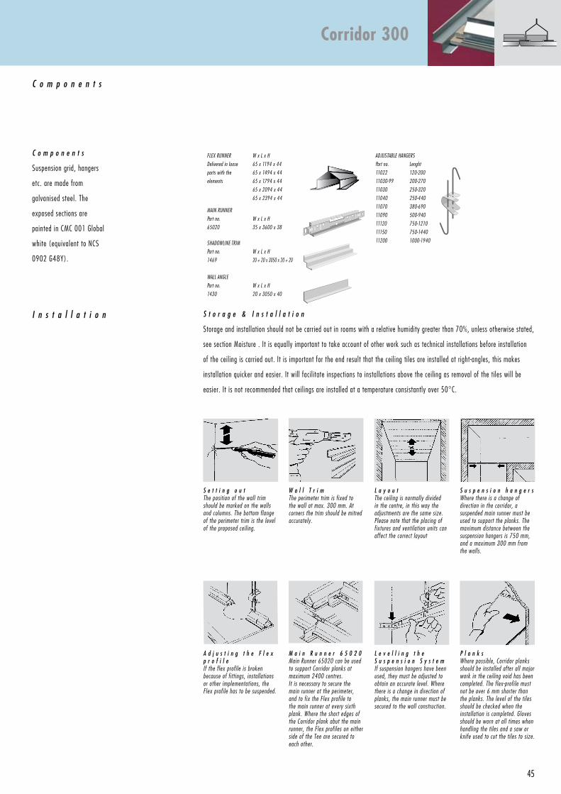
C o m p o n e n t s
Flex runner
Delivered in loose
parts with the
elements
W x l x H
65 x 1194 x 44
65 x 1494 x 44
65 x 1794 x 44
65 x 2094 x 44
65 x 2394 x 44
ADJuStAble HAngerS
Part no. lenght
11022 120-200
11030-99 200-270
11030 250-320
11040 250-440
11070 380-690
11090 500-940
11120 750-1210
11150 750-1440
11200 1000-1940
MAin runner
Part no.
65020
W x l x H
35 x 3600 x 38
SHADOWline triM
Part no.
1469
W x l x H
20 + 20 x 3050 x 20 + 20
WAll Angle
Part no.
1430
W x l x H
20 x 3050 x 40
I n s t a l l a t i o n
C o m p o n e n t s
Suspension grid, hangers
etc. are made from
galvanised steel. The
exposed sections are
painted in CMC 001 Global
white (equivalent to NCS
0902 G48Y).
S e t t i n g o u tthe position of the wall trim should be marked on the walls and columns. the bottom flange of the perimeter trim is the level of the proposed ceiling.
L a y o u tthe ceiling is normally divided in the centre, in this way the adjustments are the same size. Please note that the placing of fixtures and ventilation units can affect the correct layout
S u s p e n s i o n h a n g e r sWhere there is a change of direction in the corridor, a suspended main runner must be used to support the planks. the maximum distance between the suspension hangers is 750 mm, and a maximum 300 mm from the walls.
W a l l T r i mthe perimeter trim is fixed to the wall at max. 300 mm. At corners the trim should be mitred accurately.
M a i n R u n n e r 6 5 0 2 0 Main runner 65020 can be used to support Corridor planks at maximum 2400 centres.it is necessary to secure the main runner at the perimeter, and to fix the Flex profile to the main runner at every sixth plank. Where the short edges of the Corridor plank abut the main runner, the Flex profiles on either side of the tee are secured to each other.
P l a n k sWhere possible, Corridor planks should be installed after all major work in the ceiling void has been completed. the flex-profile must not be over 6 mm shorter than the planks. the level of the tiles should be checked when the installation is completed. gloves should be worn at all times when handling the tiles and a saw or knife used to cut the tiles to size.
A d j u s t i n g t h e F l e x p r o f i l e if the flex profile is broken because of fittings, installations or other implementations, the Flex profile has to be suspended.
L e v e l l i n g t h e S u s p e n s i o n S y s t e mif suspension hangers have been used, they must be adjusted to obtain an accurate level. Where there is a change in direction of planks, the main runner must be secured to the wall construction.
Corridor 300
46
0563
47
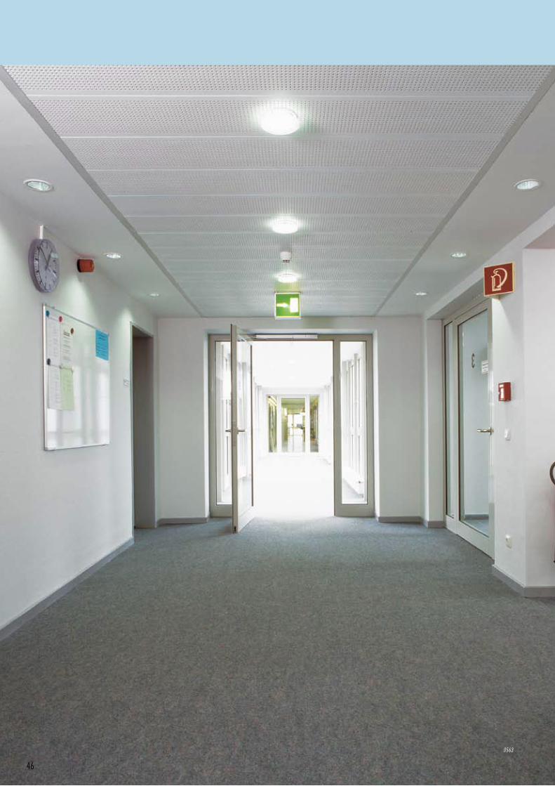
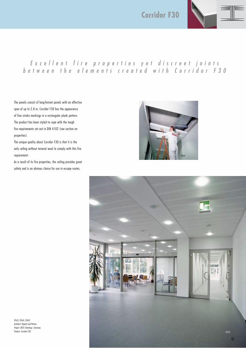
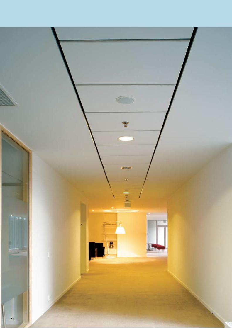
The panels consist of long-format panels with an effective
span of up to 2.8 m. Corridor F30 has the appearance
of fine stroke markings in a rectangular plank pattern.
The product has been styled to cope with the tough
fire requirements set out in DIN 4102 (see section on
properties).
The unique quality about Corridor F30 is that it is the
only ceiling without mineral wool to comply with this fire
requirement.
As a result of its fire properties, the ceiling provides great
safety and is an obvious choice for use in escape routes.
0563, 0564, 0560:
Architect: Hupach und Partner
Project: DeSY, Hamburg - germany
Product: Corridor F30
E x c e l l e n t f i r e p r o p e r t i e s y e t d i s c r e e t j o i n t sb e t w e e n t h e e l e m e n t s c r e a t e d w i t h C o r r i d o r F 3 0
Corridor F30
0560
0564
Max. 2800Max. 2800
48
Measurements are in mm.
D e t a i l
P e r f o r a t i o n
Globe: G1
Quadril: Q1
Micro: M1
Regula: R
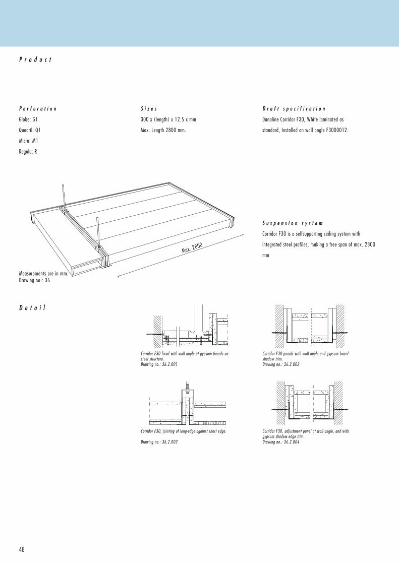
P r o d u c t
S i z e s
300 x (length) x 12.5 x mm
Max. Length 2800 mm.
D r a f t s p e c i f i c a t i o n
Danoline Corridor F30, White laminated as
standard, Installed on wall angle F3000012.
Drawing no.: 36
S u s p e n s i o n s y s t e m
Corridor F30 is a selfsupporting ceiling system with
integrated steel profiles, making a free span of max. 2800
mm
Corridor F30, adjustment panel at wall angle, and with gypsum shadow edge trim.Drawing no.: 36.2.004
Corridor F30, jointing of long-edge against short edge.
Drawing no.: 36.2.003
Corridor F30 fixed with wall angle at gypsum boards on steel structure.Drawing no.: 36.2.001
Corridor F30 panels with wall angle and gypsum board shadow trim.Drawing no.: 36.2.002
49
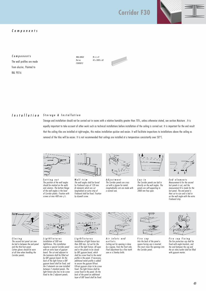
S t o r a g e & I n s t a l l a t i o n
Storage and installation should not be carried out in rooms with a relative humidity greater than 70%, unless otherwise stated, see section Moisture . It is
equally important to take account of other work such as technical installations before installation of the ceiling is carried out. It is important for the end result
that the ceiling tiles are installed at right-angles, this makes installation quicker and easier. It will facilitate inspections to installations above the ceiling as
removal of the tiles will be easier. It is not recommended that ceilings are installed at a temperature consistantly over 50°C.
C o m p o n e n t s
WAll Angle
Part no.
F3000012
W x l x H
40 x 3000 x 60
I n s t a l l a t i o n
C o m p o n e n t s
The wall profiles are made
from aluzinc. Painted to
RAL 9016
S e t t i n g o u tthe position of the wall angles should be marked on the walls and columns. the bottom flange of the wall angles is the level of Corridor planks. Fixation with screws at max 400 mm c/c.
A d j u s t m e n t the Corridor panels are cross cut with a jigsaw for metal. longitudinally cuts are made with a normal saw.
F i r e c a pinto the back of the panel a square furring cap is inserted. this must close the openings into the Corridor panel.
A i r i n l e t s a n d o u t l e t sCutting out for opening is done by a jigsaw, from the front side. Final adjustment by a fine tooth saw or a Stanley knife.
L i g t h f i x t u r e sinstallation of 300 mm lightfixture. this installation requires a special Corridor panel with an extra layer of gypsum board. the cut end adjacent to the luminarie shall be fil led out by gKF gypsum board. On the back of the light fixture a gKF gypsum board shall be fixed, and the 3 elements are now installed between 2 standard panels. the light fixture also has to be screw fixed to the 2 adjacent panels.
W a l l t r i mthe wall angles shall be furred by Fireboard srips of 120 mm. At elements which are cut longitudinal an extra strip of Fireboard shall be fixed. Fixation by drywall screw.
L a y - i n the Corridor panels are laid in directly on the wall angles. the panels are self-supporting to 2800 mm free span.
E n d - e l e m e n t sMeasurement A for the second last panels is set, and the measurement b is made for the last panel. the end panel is then cut to size and is laid in on the wall angle with the extra Fireboard strip.
C l o s i n gthe second last panel can now be laid in between the end panel and the third last panel.Cotten gloves should be worn at all time when handling the Corridor panels.
L i g t h f i x t u r e sinstallation of light fixture less than 300 mm. Cut out for the size of the light fixture. All open end in the panels to be closed by gKF gypsum board, which shall be screw fixed to the metal profile in the panel. if necessary, additional metal profile is added to secure the gypsum fill -out. Fill -out gypsum strips to be screw fixed. the light fixture shall be screw fixed to the panel. On the back of the panel an additional layer of gKF board shall be fixed.
F i r e c a p f i x i n gthe fire protection cap shall be fixed with angle brackets, and the void between the cap and the air inlet/outlet shall be fil led with gypsum mortar.
A B
Corridor F30
50
1129
51
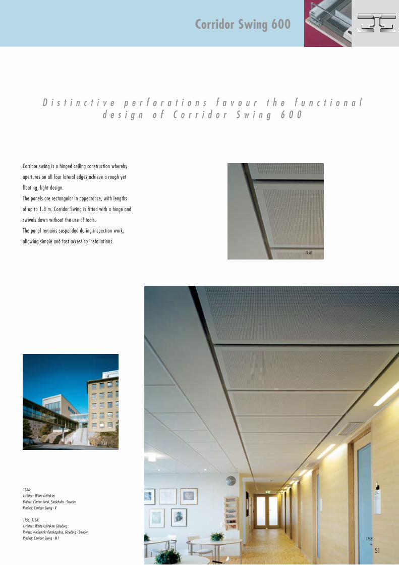
Corridor swing is a hinged ceiling construction whereby
apertures on all four lateral edges achieve a rough yet
floating, light design.
The panels are rectangular in appearance, with lengths
of up to 1.8 m. Corridor Swing is fitted with a hinge and
swivels down without the use of tools.
The panel remains suspended during inspection work,
allowing simple and fast access to installations.
D i s t i n c t i v e p e r f o r a t i o n s f a v o u r t h e f u n c t i o n a ld e s i g n o f C o r r i d o r S w i n g 6 0 0
1266:
Architect: White Arkitekter
Project: Clarion Hotel, Stockholm - Sweden
Product: Corridor Swing - r
1156, 1158:
Architect: White Arkitekter göteborg
Project: Medicinskt Kunskapshus, göteborg - Sweden
Product: Corridor Swing - M1
Corridor Swing 600
1158
1156
1158
600
1200, 1500, 1800
52
Measurements are in mm.
D e t a i l
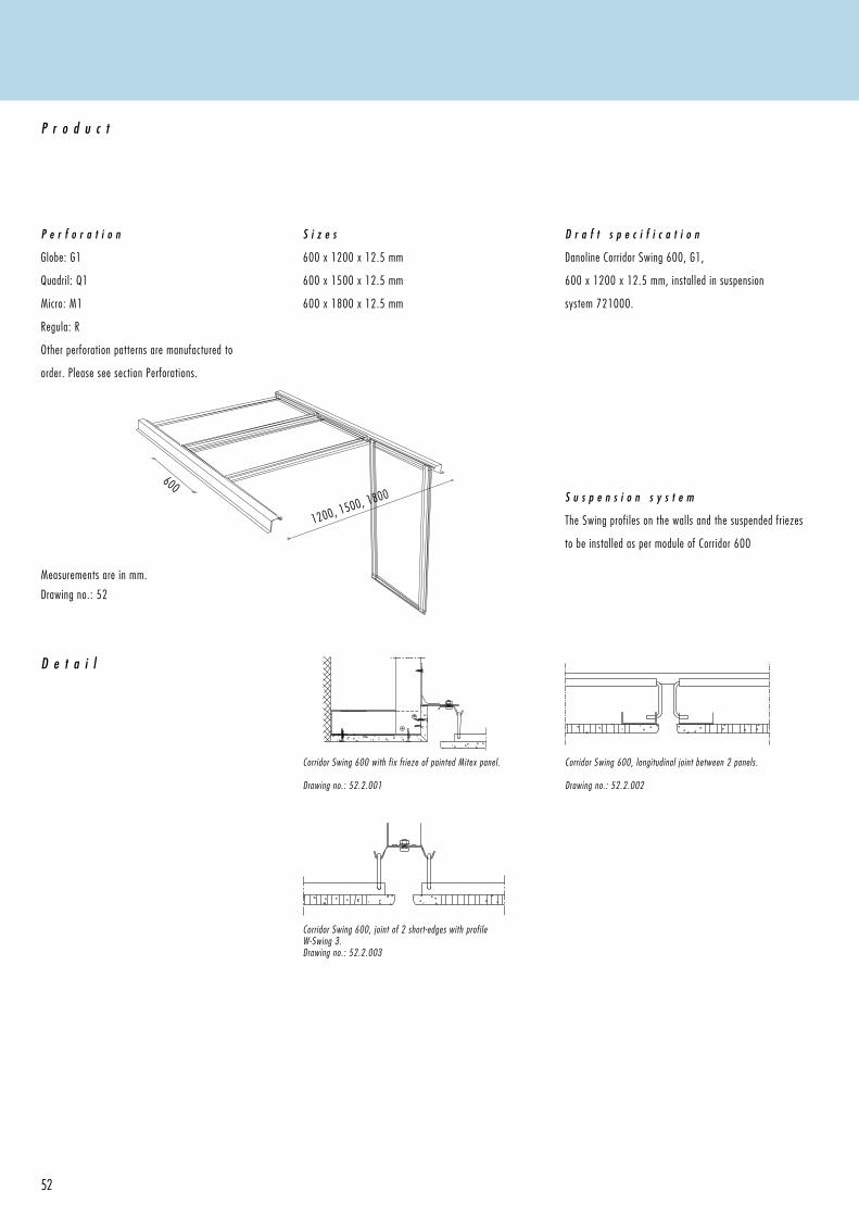
P e r f o r a t i o n
Globe: G1
Quadril: Q1
Micro: M1
Regula: R
Other perforation patterns are manufactured to
order. Please see section Perforations.
P r o d u c t
S i z e s
600 x 1200 x 12.5 mm
600 x 1500 x 12.5 mm
600 x 1800 x 12.5 mm
D r a f t s p e c i f i c a t i o n
Danoline Corridor Swing 600, G1,
600 x 1200 x 12.5 mm, installed in suspension
system 721000.
Drawing no.: 52
S u s p e n s i o n s y s t e m
The Swing profiles on the walls and the suspended friezes
to be installed as per module of Corridor 600
Corridor Swing 600, joint of 2 short-edges with profile W-Swing 3.Drawing no.: 52.2.003
Corridor Swing 600 with fix frieze of painted Mitex panel.
Drawing no.: 52.2.001
Corridor Swing 600, longitudinal joint between 2 panels.
Drawing no.: 52.2.002
53
S t o r a g e & I n s t a l l a t i o n
Storage and installation should not be carried out in rooms with a relative humidity greater than 70%, unless otherwise stated, see section Moisture . It is
equally important to take account of other work such as technical installations before installation of the ceiling is carried out. It is important for the end result
that the ceiling tiles are installed at right-angles, this makes installation quicker and easier. It will facilitate inspections to installations above the ceiling as
removal of the tiles will be easier. It is not recommended that ceilings are installed at a temperature consistantly over 50°C.
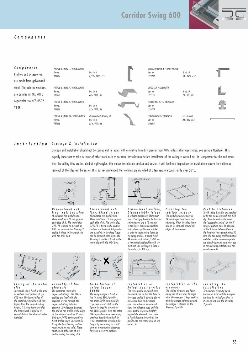
PrOFile W-SWing 1 / WHite PAinteD
Part no.
729196
W x l x H
8/12 x 2400 x 55
PrOFile W-SWing 5 / WHite PAinteD
Part no.
729200
W x l x H
68 x 2400 x 53
PrOFile W-SWing 2 / WHite PAinteD
Part no.
730162
W x l x H
40 x 2400 x 16
MetAl CliP / gAlvAnizeD
Part no.
721175
W x l x H
70 x 58 x 80
PrOFile W-SWing 3 / WHite PAinteD
Part no.
729198
W x l x H
92 x 2400 x 16
SCreW/nut W34 / gAlvAnizeD
Part no.
718473
PrOFile W-SWing 4A / WHite PAinteD
Part no.
731618
(Combined with W-swing 2)
W x l x H
85 x 2400 x 66
SWing HAnger / unPAinteD
Part no.
SW6Mb
incl. element
Ø4 x 582 x 53
I n s t a l l a t i o n
C o m p o n e n t s
C o m p o n e n t s
Profiles and accessories
are made from galvanised
steel. The painted sections
are painted in RAL 9010
(equivalent to NCS 0502
Y14R).
P l a n n i n g t h e c e i l i n g s u r f a c ethe module measurement is 24 mm larger than the actual elements. When installed there will be 24 mm gab around all edges of the element.
P r o f i l e d i s t a n c e sthe W swing 2 profiles are installed under the metal clips with the W34 clip. now the distance between the “suspension points” on the W swing 2 profiles must be adjusted, so the distance between them is the length of the element minus 50 mm. the two swing profiles must be installed, so the suspension points are directly opposite each other due to the following installation of the actual elements.
F i x i n g o f t h e m e t a l c l i pthe metal clip is fixed to the wall or vertical steel profiles at c/c 800 mm. the lowest edge of the metal clip should be 65 mm higher than the desired ceiling height. it is very important that the frame work is rigid so it cannot deform the elements when installed.
D i m e n s i o n a l o u t l i n e , D i s m o u n t a b l e f r i e z eM indicate module line. there must be a 12 mm gap towards the Corridor swing element and a 18 mm gap to the frieze. Horizontal u-profiles and vertical C-profiles are installed in order to create a rigid frame for the swing profiles. W-swing 2 and 4A profiles are fixed at c/c 800 mm in the vertical steel profiles with the W34 bolt. the wall angle is fixed to the wall at c/c 400 mm.
F i n i s h i n g t h e i n s t a l l a t i o nthe element is swung up to horizontal level and the hangers are held in vertical position so it can be slid into the W-swing 2 profile.
I n s t a l l a t i o n o f t h e e l e m e n t sthe ceiling elements are hung along one of the sides to begin with. the element is kept vertical with the hanger pointing up and the hanger is clasped on the W-swing 2 profile.
I n s t a l l a t i o n o f s w i n g h a n g e r S W 6 M Bthe swing hanger is fixed to the fastened SW15 profile, the other SW15 swing profile is pushed into its slot, so the hanger is fixed in the hole of the SW15 profile. now the other SW15 profile can be fixed using previous described method. it is not recommend installing the hanger by tensioning as it will give an inappropriate sideways force on the SW15 profiles.
D i m e n s i o n a l o u t -l i n e , w a l l j u n c t i o nM indicates the module line. there must be a 12 mm gap on each side of M. the metal clip, 721175 is fixed to the wall at 800 c/c mm and the W-swing 2 profile is fixed to the metal clip with the W34 bolt.
D i m e n s i o n a l o u t -l i n e , F i x e d f r i e z eM indicates the module line. there must be a 12 mm gap on each side of M. the metal clip, 721175 is fixed to the vertical profiles and horizontal u-profiles are installed so the fixed frieze can be screwed onto them. the W-swing 2 profile is fixed to the metal clip with the W34 bolt.
A s s e m b l y o f t h e e l e m e n t sthe elements come with depressed fittings. the SW15 profiles are fixed with the supplied screws through the depressed fitting into the element. the distance between the end of the profile to the edge of the element must be 15 mm. Only one SW15 swing profile is fixed at this stage. the base for fixing the load bearing profiles must be plane and solid. there must be no deflection of the profile during the fixing of it.
Corridor Swing 600
50 mm
I n s t a l l a t i o n o f S w i n g c r o s s p r o f i l e the cross profile is placed onto the metal clip so that the hole in the cross profile is directly above the centre hole in the metal clip. the foil cover is removed from the adhesive pads and the cross profile is pressed tightly against the element. the screw is fixed through the hole in the profile and the centre hole in the metal clip.
MM M
54
1072
55
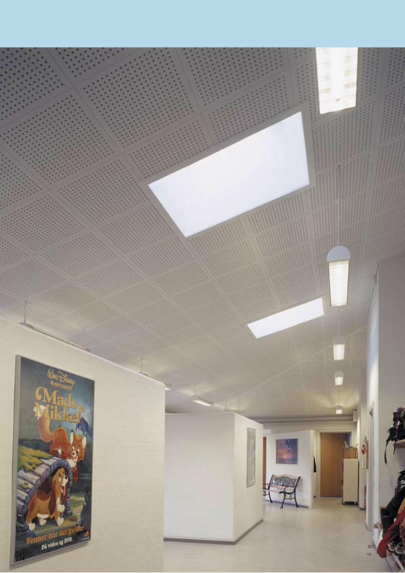
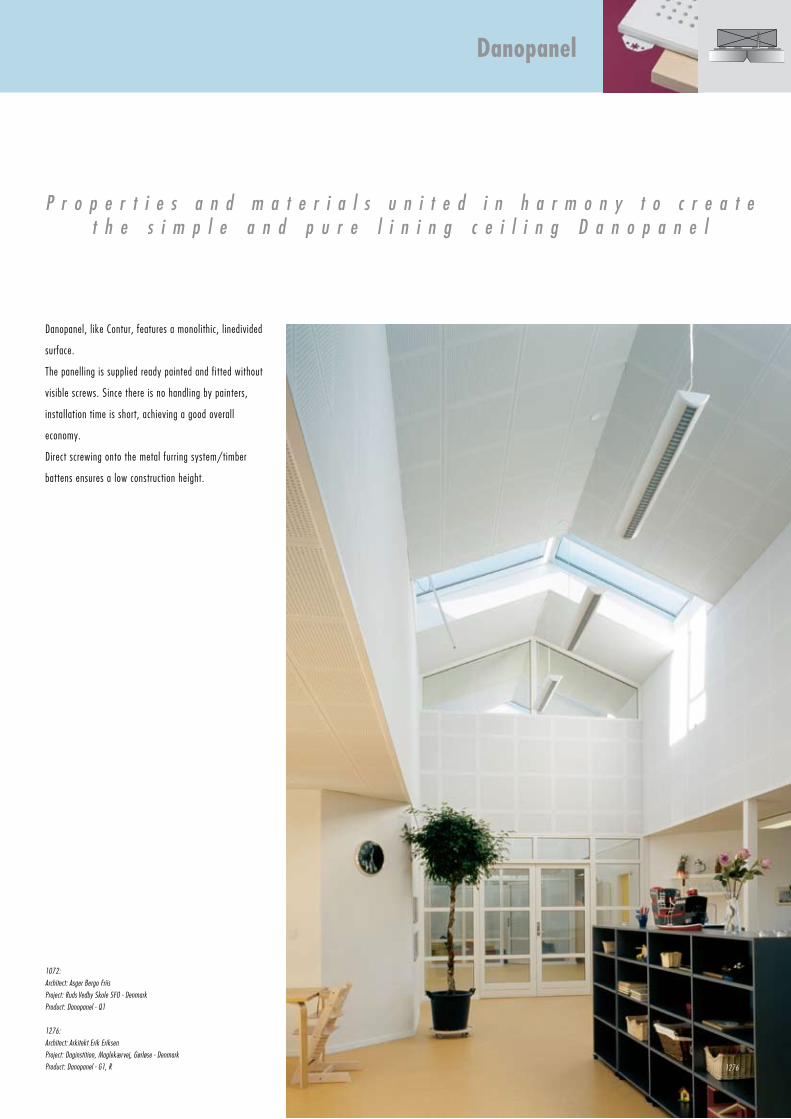
Danopanel, like Contur, features a monolithic, linedivided
surface.
The panelling is supplied ready painted and fitted without
visible screws. Since there is no handling by painters,
installation time is short, achieving a good overall
economy.
Direct screwing onto the metal furring system/timber
battens ensures a low construction height.
P r o p e r t i e s a n d m a t e r i a l s u n i t e d i n h a r m o n y t o c r e a t et h e s i m p l e a n d p u r e l i n i n g c e i l i n g D a n o p a n e l
1072:
Architect: Asger Bergo Friis
Project: Ruds Vedby Skole SFO - Denmark
Product: Danopanel - Q1
1276:
Architect: Arkitekt Erik Eriksen
Project: Daginstition, Maglekærvej, Gørløse - Denmark
Product: Danopanel - G1, R
Danopanel
1276
600
600
300
300
56
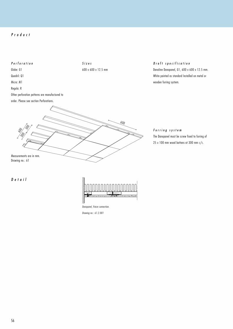
Measurements are in mm.Drawing no.: 61
D e t a i l
P e r f o r a t i o n
Globe: G1
Quadril: Q1
Micro: M1
Regula: R
Other perforation patterns are manufactured to
order. Please see section Perforations.
P r o d u c t
S i z e s
600 x 600 x 12.5 mm
D r a f t s p e c i f i c a t i o n
Danoline Danopanel, G1, 600 x 600 x 12.5 mm.
White painted as standard Installed on metal or
wooden furring system.
Danopanel, frieze connection.
Drawing no.: 61.2.001
F u r r i n g s y s t e m
The Danopanel must be screw fixed to furring of
25 x 100 mm wood battens at 300 mm c/c.
57
S t o r a g e & I n s t a l l a t i o n
Storage and installation should not be carried out in rooms with a relative humidity greater than 70%, unless otherwise
stated, see section Moisture . It is equally important to take account of other work such as technical installations before
installation of the ceiling is carried out. It is important for the end result that the ceiling tiles are installed at right-
angles, this also makes installation quicker & easier. It is not recommended that ceilings are installed at a temperature
consistantly over 50°C.
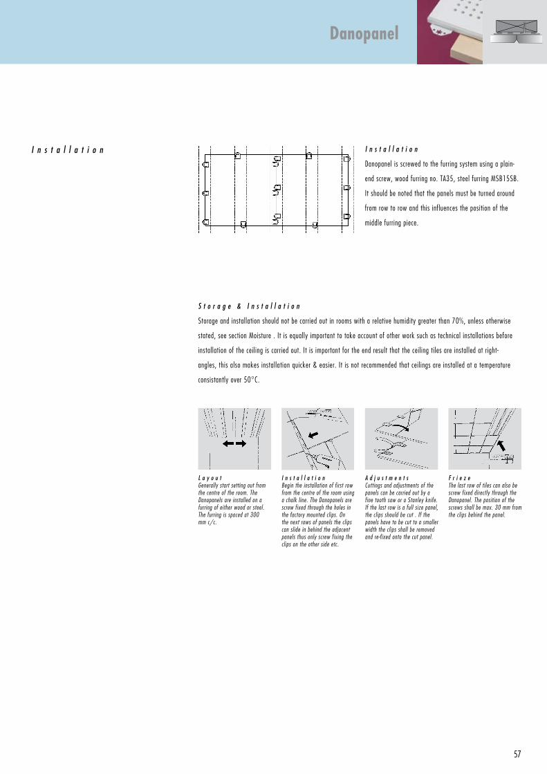
I n s t a l l a t i o n I n s t a l l a t i o n
Danopanel is screwed to the furring system using a plain-
end screw, wood furring no. TA35, steel furring MSB15SB.
It should be noted that the panels must be turned around
from row to row and this influences the position of the
middle furring piece.
L a y o u tGenerally start setting out from the centre of the room. The Danopanels are installed on a furring of either wood or steel.The furring is spaced at 300 mm c/c.
F r i e z e The last row of tiles can also be screw fixed directly through the Danopanel. The position of the screws shall be max. 30 mm from the clips behind the panel.
A d j u s t m e n t sCuttings and adjustments of the panels can be carried out by a fine tooth saw or a Stanley knife. If the last row is a full size panel, the clips should be cut . If the panels have to be cut to a smaller width the clips shall be removed and re-fixed onto the cut panel.
I n s t a l l a t i o nBegin the installation of first row from the centre of the room using a chalk line. The Danopanels are screw fixed through the holes in the factory mounted clips. On the next rows of panels the clips can slide in behind the adjacent panels thus only screw fixing the clips on the other side etc.
Danopanel
58
1079
59
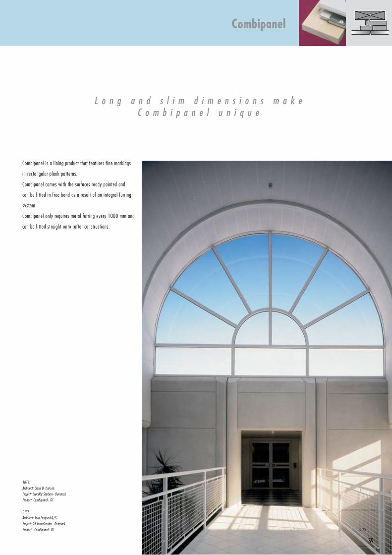
Combipanel is a lining product that features fine markings
in rectangular plank patterns.
Combipanel comes with the surfaces ready painted and
can be fitted in free bond as a result of an integral furring
system.
Combipanel only requires metal furring every 1000 mm and
can be fitted straight onto rafter constructions.
L o n g a n d s l i m d i m e n s i o n s m a k eC o m b i p a n e l u n i q u e
1079:
Architect: Claus B. Hansen
Project: Brøndby Stadion - Denmark
Product: Combipanel - G1
0133:
Architect: Jørn Langvad A/S
Project: Q8 hovedkontor - Denmark
Product: Combipanel - G1
Combipanel
0133
Max. 1000
60
Combipanel, wall connection.
Drawing no.: 65.2.001
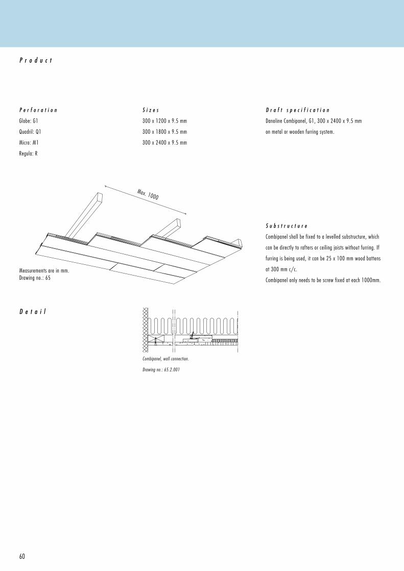
S u b s t r u c t u r e
Combipanel shall be fixed to a levelled substructure, which
can be directly to rafters or ceiling joists without furring. If
furring is being used, it can be 25 x 100 mm wood battens
at 300 mm c/c.
Combipanel only needs to be screw fixed at each 1000mm.
Measurements are in mm.Drawing no.: 65
D e t a i l
P e r f o r a t i o n
Globe: G1
Quadril: Q1
Micro: M1
Regula: R
P r o d u c t
S i z e s
300 x 1200 x 9.5 mm
300 x 1800 x 9.5 mm
300 x 2400 x 9.5 mm
D r a f t s p e c i f i c a t i o n
Danoline Combipanel, G1, 300 x 2400 x 9.5 mm
on metal or wooden furring system.
61
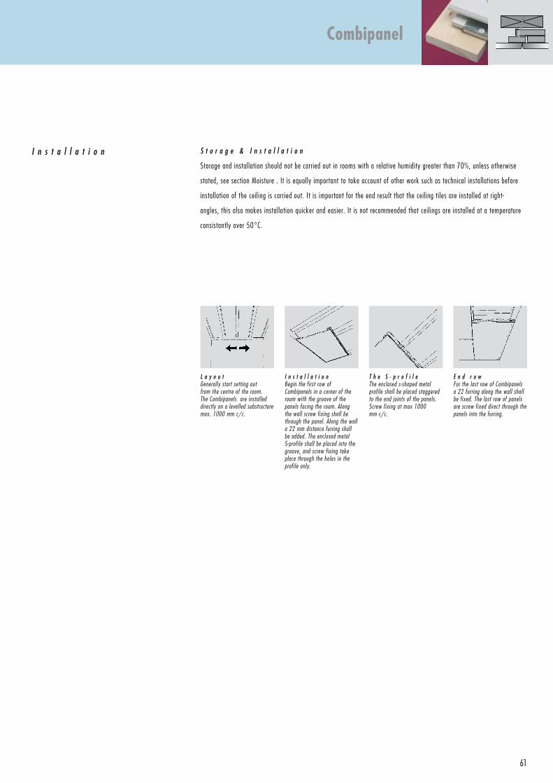
S t o r a g e & I n s t a l l a t i o n
Storage and installation should not be carried out in rooms with a relative humidity greater than 70%, unless otherwise
stated, see section Moisture . It is equally important to take account of other work such as technical installations before
installation of the ceiling is carried out. It is important for the end result that the ceiling tiles are installed at right-
angles, this also makes installation quicker and easier. It is not recommended that ceilings are installed at a temperature
consistantly over 50°C.
I n s t a l l a t i o n
L a y o u tGenerally start setting out from the centre of the room. The Combipanels are installed directly on a levelled substructure max. 1000 mm c/c.
I n s t a l l a t i o nBegin the first row of Combipanels in a corner of the room with the groove of the panels facing the room. Along the wall screw fixing shall be through the panel. Along the wall a 22 mm distance furring shall be added. The enclosed metal S-profile shall be placed into the groove, and screw fixing take place through the holes in the profile only.
T h e S - p r o f i l eThe enclosed s-shaped metal profile shall be placed staggered to the end joints of the panels.Screw fixing at max 1000 mm c/c.
E n d r o wFor the last row of Combipanels a 22 furring along the wall shall be fixed. The last row of panels are screw fixed direct through the panels into the furring.
Combipanel
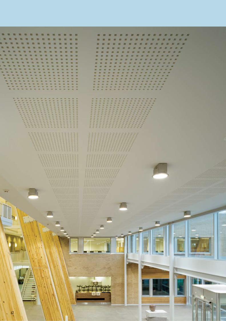
62
1246
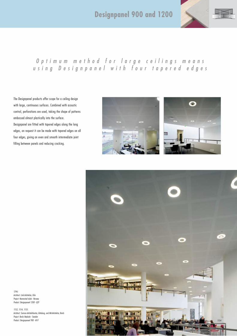
63
The Designpanel products offer scope for a ceiling design
with large, continuous surfaces. Combined with acoustic
control, perforations are used, taking the shape of patterns
embossed almost plastically into the surface.
Designpanel are fitted with tapered edges along the long
edges, on request it can be made with tapered edges on all
four edges, giving an even and smooth intermediate joint
fil l ing between panels and reducing cracking.
O p t i m u m m e t h o d f o r l a r g e c e i l i n g s m e a n su s i n g D e s i g n p a n e l w i t h f o u r t a p e r e d e d g e s
1246:
Architect: Link Arkitekter, Oslo
Project: Nannestad skole - Norway
Product: Designpanael 1200 - Q2F
1153, 1154, 1155:
Architect: Semren Arkitektkontor, Göteborg, and MA Arkitekter, Borås
Project: Borås Højskole - Sweden
Product: Designpanael 900 - M1F
Designpanel 900 and 1200
1154
11551153
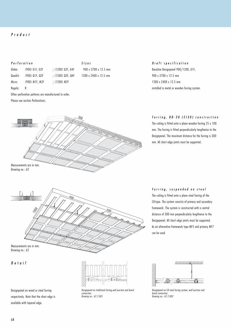
300
900
3001000
64
Designpanel on wood or steel furring
respectively. Note that the short edge is
available with tapered edge.
F u r r i n g , s u s p e n d e d o n s t e e l
The ceiling is fitted onto a plane steel furring of the
CD-type. The system consists of primary and secondary
framework. The system is constructed with a central
distance of 300 mm perpendicularly lengthwise to the
Designpanel. All short edge joints must be supported.
As an alternative framework type MF5 and primary MF7
can be used.
P e r f o r a t i o n
Globe: (900) G1F, G2F ; (1200) G2F, G4F
Quadril: (900) Q1F, Q2F ; (1200) Q2F, Q4F
Micro: (900) M1F, M2F ; (1200) M2F
Regula: R
Other perforation patterns are manufactured to order.
Please see section Perforations.
P r o d u c t
S i z e s
900 x 2700 x 12.5 mm
1200 x 2400 x 12.5 mm
D r a f t s p e c i f i c a t i o n
Danoline Designpanel 900/1200, G1F,
900 x 2700 x 12.5 mm
1200 x 2400 x 12.5 mm
installed in metal or wooden furring system.
F u r r i n g , B D - 3 0 ( E I 3 0 ) c o n s t r u c t i o n
The ceiling is fitted onto a plane wooden furring 25 x 100
mm. The furring is fitted perpendicularly lengthwise to the
Designpanel. The maximum distance for the furring is 300
mm. All short edge joints must be supported.
D e t a i l
Designpanel on traditional furring,wall junction and board connection.Drawing no.: 62.2.001
Measurements are in mm.Drawing no.: 62
Measurements are in mm.Drawing no.: 62
Designpanel on CD steel furring system, wall junction and board connection.Drawing no.: 62.2.002
65
Designpanel 900 and 1200
B D - 3 0 ( E I 3 0 ) c o n s t r u c t i o n
Damp proof barrier is placed over the furring. If the damp proof
membrane is placed immediately over the perforations, but under
the furring, the ability to absorb the sound is severely reduced.
The present absorption data depends on a 150 my (µ) plastic
foil. A foil with any other thickness will affect the acoustic
capacities. In order to achieve a BD-30 construction, 250 mm
rock wool insulation must be a part of the construction.
F u r r i n g , w o o d
The ceiling is fitted to a plane wooden furring 25 x 100 mm.
The furring is fitted to the rafters or beams with a maximum
central distance of 1000 mm. The furring is
fitted perpendicular lengthwise to the ceiling
panel. The maximum c/c distance of
the furring is 300 mm. The short
edges of the panel joints must
be supported.
F u r r i n g , s t e e l
The ceiling is fitted to a plane steel furring of the CD-2
type. The system consists of primary runners at max 900
mm c/c, and secondary runners at 300 mm c/c. Along
all walls and edges the wall profiles UD 28 x 27 are fixed
and secured to the furring at max 400 mm. The top part
of the hangers, of the nonius model, are secured to the
above construction at 900 and attached
to the primary CD-60 runners
with the lower part of the
hanger. The cross connector is
placed per 300 mm and the
underlying secondary profiles
are secured into them. The short edges of the panel must
be supported along its entire lenght by fixing the panel to
the furring system.
G r o u p i n g
The starting point for the fitting of the design panels is
where a level line can be achieved through the whole
fitting area. The first row is fitted along a string in order
for the perforated sections to be in line. The fitting is
started in the middle of the room, as far as possible, and
the Designpanels are fitted from the middle towards each
side in order for the friezes to
be equally wide. The panels
are delivered undersized and
must be fitted with a distance
of up to 4 mm.
The perforated sections must be in line with their own line
and be perpendicular to the sections next to them.
F i t t i n g
The Designpanel is screwed onto either wood or steel at
every 200 mm along the short edges of the panel and in
section sizes of 300 x 600 mm on the rest of the panels,
see drawing 62.
E x p a n s i o n j o i n t s
Panel area more than 70 m², or in cases where one of the
side lengths extend 15 m, must be divided by an expansion
joint. Slip tape is fitted with an acrylic sealants. Mount the
gypsum panels with an edge trim towards the connection,
which will give an exact finish and secure attachment of
the sealant.
F i l l i n g , i n g e n e r a l
Filling of Designpanels deviates from the general fil l ing
instructions according to Danogips board constructions,
as the perforation gives certain limits in connection with
the fil l ing. The following describes the best possible way
of a satisfactory fil l ing, which takes cracks and a ceiling
surface without visible joints into account. The condition
is, however, that the instructions are followed accurately
and that there are no movements in the building and the
construction of the ceiling.
Straight cut short edges and
joints are fil led with Uniflot
fil ler. Ensure that straight and
cut edges have been bevelled
before the fil l ing is started.
Danogips Grund and Finish is used for fil l ing screw heads
and tapered joints. Tapered joints must be stripped with
paper fil l ing tape. Cover the perforations with tape before
fil l ing the joints
F i l l i n g p r o c e s s A , s t r a i g h t e d g e s
Sprinkle Uniflot fil l ing powder into pure water and stir well
by hand in order for it to reach a homogenous texture. Fill
the joints well and pinch the fil ler up between the panels.
Cut off any excess material after 45 minutes, Uniflot
hardens quickly. It is important to remove any excess
fil ler in order to obtain a clean transition to the ceil-
ing surface. Grind off minor irregularities. Finish off
with a fil l ing as described under third fil l ing.
F i l l i n g p r o c e s s B , t a p e r e d e d g e s
– First fil l ing
Use a 2-inch fil l ing knife and apply the Grund fil ler, which
is watery, so it spreads onto the fil l ing tape and into the
crack between the panels. The fil l ing ought to be carried
out in such a way that a final grinding is unnecessary once
the fil ler has hardened completely.
– Second fil l ing
Grund fil ler is also used for the second fil l ing. By resting
the hand against the Designpanel the fil l ing knife is
wielded along the middle of the first fil l ing - first on one
side then on the other. Use a 2-inch fil l ing knife and apply
the fil ler twice. The fil l ing ought to be carried out in such a
way that a final grinding is unnecessary once the fil ler has
dried completely after 24 hours.
– Third fil l ing
Use Finish pastös for the third fil l ing, which has to be a
very thin coat and use a 4-inch fil l ing knife. Wield the
fil l ing knife with a uniform and gliding motion in order
to minimise the final grinding. When the fil ler has dried,
sandpaper the surface.
P a i n t
On account of the acoustic felt backing use a brush or roller
in order for the primer and paint not to stick to the acoustic
felt backing. Use a roller with fine mohair, which ensures a
thin coat of paint at a time. Spray painting will affect the
acoustic properties and is therefore not recommendable.
Prime the whole ceiling surface with alkyd primer in order
for the fil l ings and boards to absorb evenly. Subsequently,
finish with 1 to 2 coats of plastic paint.
C l e a n i n g a n d M a i n t e n a n c e
The treated ceiling can be vacuumed or wiped with a
damp cloth, which has been dipped in a mild solution of
synthetic detergent. After-treatment, as well as covering
of major damages and severe smudges, can be carried
out by painting with a roller, please refer to p. 119 for
instructions on painting on acoustic panels. The treatment
does not reduce the acoustic properties.
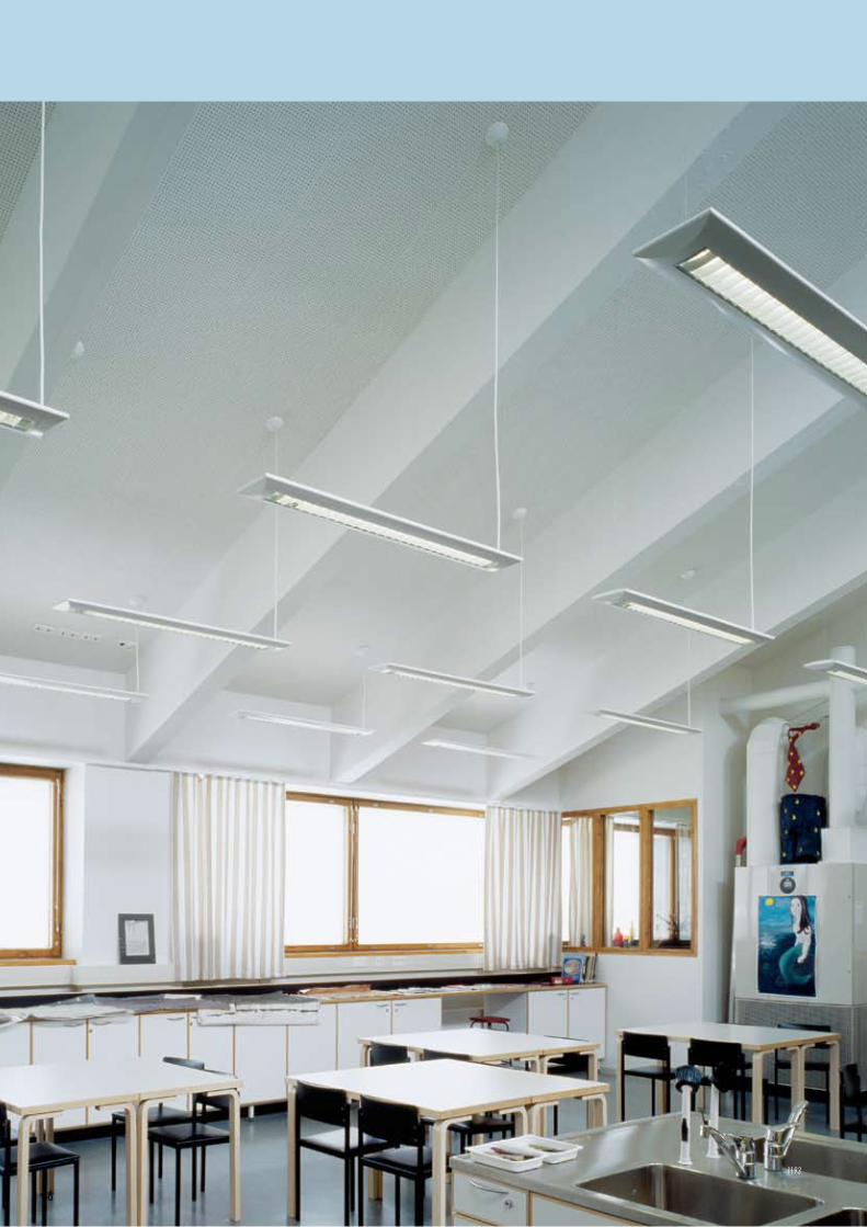
66
1193
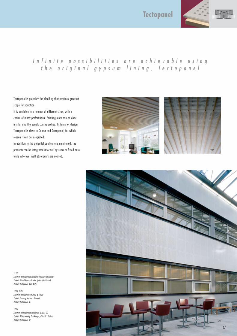
67
I n f i n i t e p o s s i b i l i t i e s a r e a c h i e v a b l e u s i n gt h e o r i g i n a l g y p s u m l i n i n g , T e c t o p a n e l
Tectopanel is probably the cladding that provides greatest
scope for variation.
It is available in a number of different sizes, with a
choice of many perforations. Painting work can be done
in situ, and the panels can be arched. In terms of design,
Tectopanel is close to Contur and Danopanel, for which
reason it can be integrated.
In addition to the potential applications mentioned, the
products can be integrated into wall systems or fitted onto
walls wherever wall absorbents are desired.
1193:
Architect: Arkkitehtitoimisto Lehto-Peltonen-Valkama Oy
Project: School Normaalikoulu, Jyväskylä - Finland
Product: Tectopanel, Alvar Aalto
1286, 1287:
Architect: Arkitektfirmaet Hune & Elkjær
Project: Korsvang, Assens - Denmark
Product: Tectopanel - G1
1205:
Architect: Arkkitehtitoimisto Larkas & Laine Oy
Project: Office building Outokumpu, Helsinki - Finland
Product: Tectopanel - Q1
Tectopanel
1205
12871286
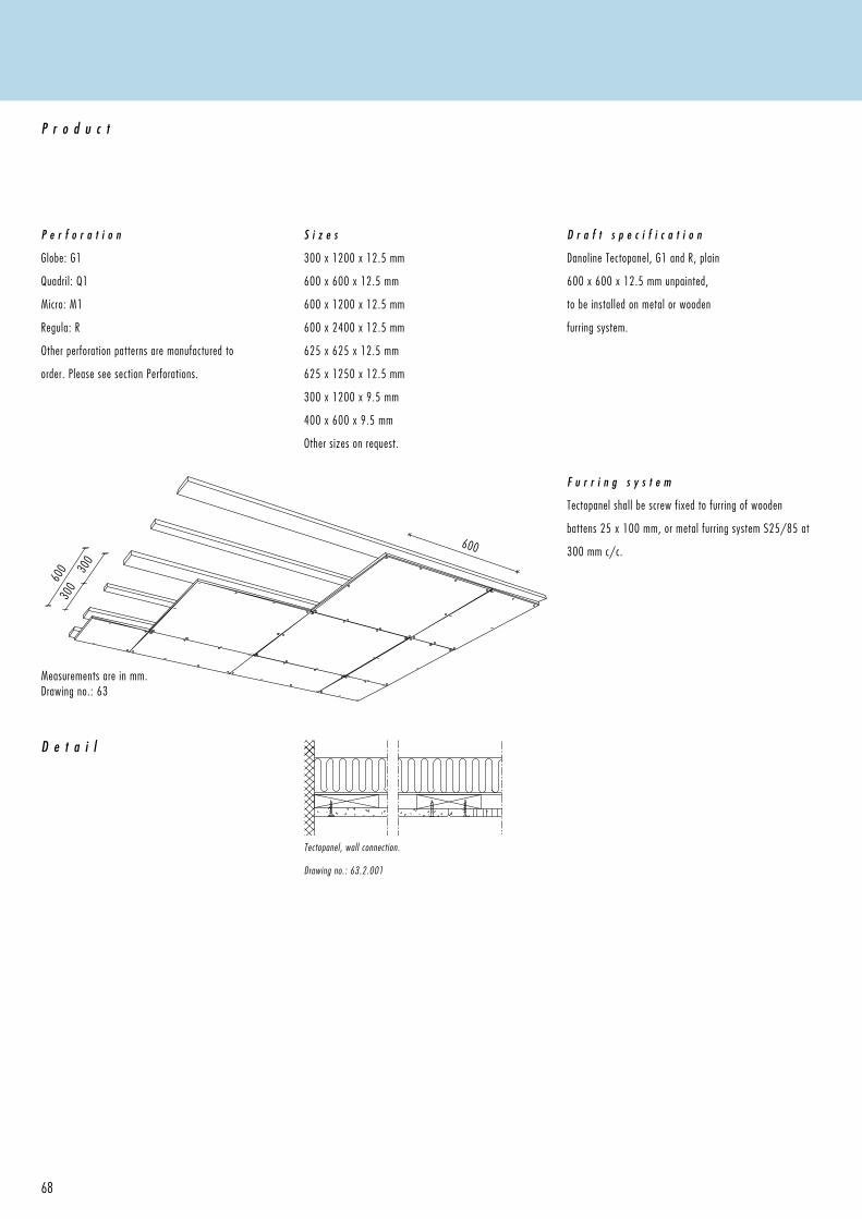
600
600 30
0
300
68
Tectopanel, wall connection.
Drawing no.: 63.2.001
F u r r i n g s y s t e m
Tectopanel shall be screw fixed to furring of wooden
battens 25 x 100 mm, or metal furring system S25/85 at
300 mm c/c.
Measurements are in mm.Drawing no.: 63
D e t a i l
P e r f o r a t i o n
Globe: G1
Quadril: Q1
Micro: M1
Regula: R
Other perforation patterns are manufactured to
order. Please see section Perforations.
P r o d u c t
S i z e s
300 x 1200 x 12.5 mm
600 x 600 x 12.5 mm
600 x 1200 x 12.5 mm
600 x 2400 x 12.5 mm
625 x 625 x 12.5 mm
625 x 1250 x 12.5 mm
300 x 1200 x 9.5 mm
400 x 600 x 9.5 mm
Other sizes on request.
D r a f t s p e c i f i c a t i o n
Danoline Tectopanel, G1 and R, plain
600 x 600 x 12.5 mm unpainted,
to be installed on metal or wooden
furring system.
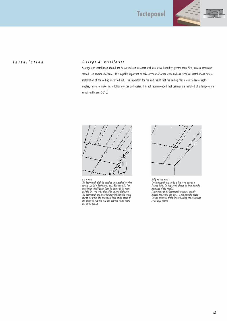
69
L a y o u tThe Tectopanels shall be installed on a levelled wooden furring size 25 x 100 mm at max. 300 mm c/c. The installation should begin from the centre of the room, and the first row to be aligned by using a chalk line. The Tectopanels are hereafter installed from the centre row to the walls. The screws are fixed at the edges of the panels at 200 mm c/c and 300 mm in the centre line of the panels.
A d j u s t m e n t sThe Tectopanels are cut by a fine tooth saw or a Stanley knife. Cutting should always be done from the front side of the panels.Screw fixing of the Tectopanels is always directly through the panels and min. 10 mm from the edges. The cut perimeter of the finished ceiling can be covered by an edge profile.
S t o r a g e & I n s t a l l a t i o n
Storage and installation should not be carried out in rooms with a relative humidity greater than 70%, unless otherwise
stated, see section Moisture . It is equally important to take account of other work such as technical installations before
installation of the ceiling is carried out. It is important for the end result that the ceiling tiles are installed at right-
angles, this also makes installation quicker and easier. It is not recommended that ceilings are installed at a temperature
consistantly over 50°C.
I n s t a l l a t i o n
Tectopanel
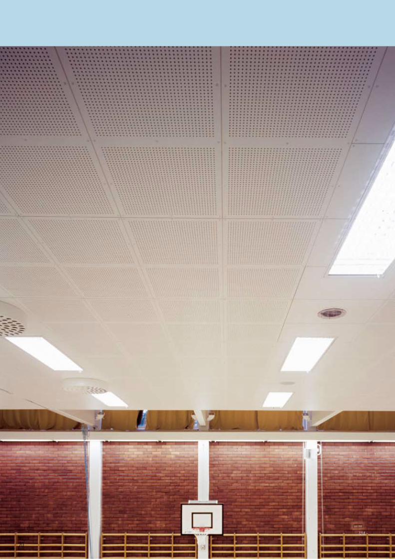
70
1218
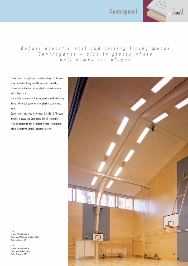
71
R o b u s t a c o u s t i c w a l l a n d c e i l i n g l i n i n g m e a n s C o n t r a p a n e l – a l s o i n p l a c e s w h e r e
b a l l g a m e s a r e p l a y e d
1218:
Architect: H & M Arkkitehdit Oy
Project: School Pohjoispuiso, Hyvinkää - Finland
Product: Contrapanel - G1F
1214:
Architect: H & M Arkkitehdit Oy
Project: School Veikkola - Finland
Product: Contrapanel - G1F
Contrapanel is a high impact resistance lining. Contrapanel
is very robust and very suitable for use in sporthalls,
schools and institutions, where physical impact on walls
and ceilings occur.
It is obvious to use acoustic Contrapanel as wall and ceiling
linings, where ball games or other physical activity take
place.
Contrapanel is tested to the German DIN 18032. The core
material is gypsum so Contrapanel has all the familiar
technical properties and the indoor climate certifications,
which characterise Danoline ceilings products.
Contrapanel
1214
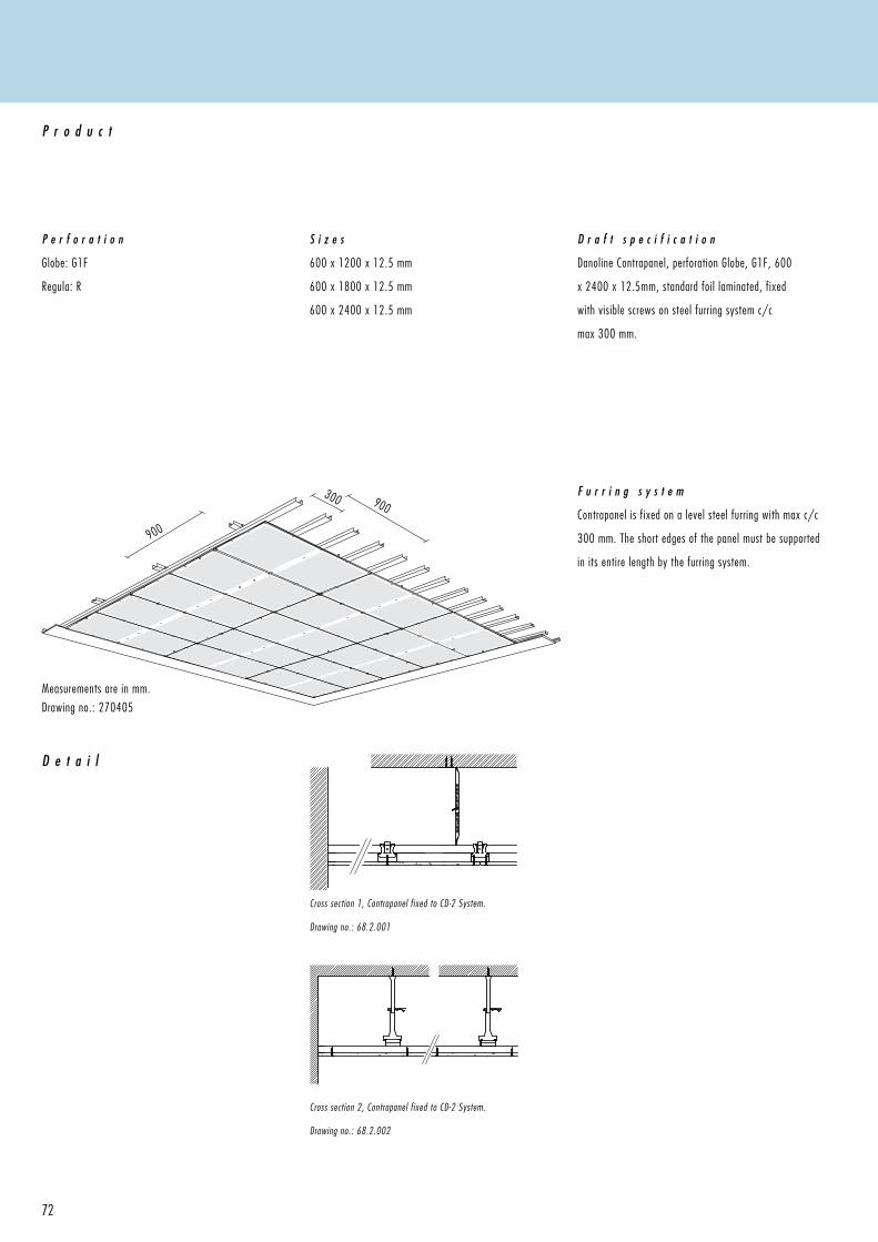
900
900
300
72
Cross section 1, Contrapanel fixed to CD-2 System.
Drawing no.: 68.2.001
F u r r i n g s y s t e m
Contrapanel is fixed on a level steel furring with max c/c
300 mm. The short edges of the panel must be supported
in its entire length by the furring system.
Measurements are in mm.
Drawing no.: 270405
D e t a i l
P e r f o r a t i o n
Globe: G1F
Regula: R
P r o d u c t
S i z e s
600 x 1200 x 12.5 mm
600 x 1800 x 12.5 mm
600 x 2400 x 12.5 mm
D r a f t s p e c i f i c a t i o n
Danoline Contrapanel, perforation Globe, G1F, 600
x 2400 x 12.5mm, standard foil laminated, fixed
with visible screws on steel furring system c/c
max 300 mm.
Cross section 2, Contrapanel fixed to CD-2 System.
Drawing no.: 68.2.002
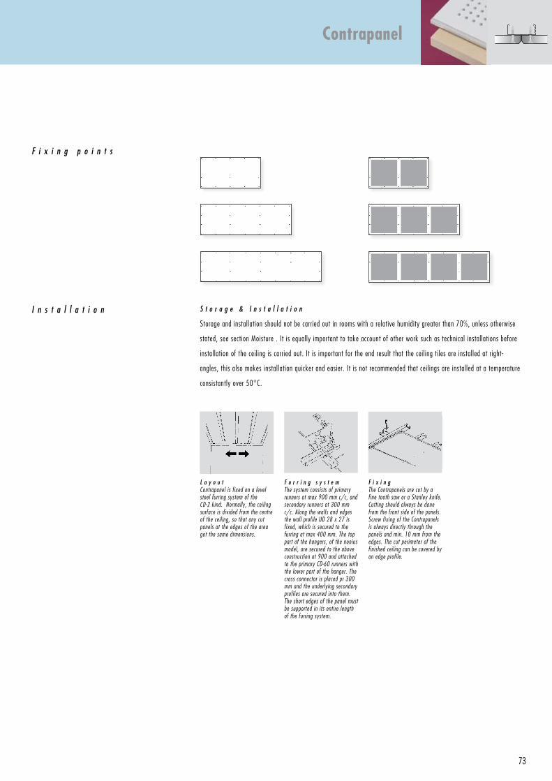
73
F i x i n g p o i n t s
F i x i n gThe Contrapanels are cut by a fine tooth saw or a Stanley knife. Cutting should always be done from the front side of the panels. Screw fixing of the Contrapanels is always directly through the panels and min. 10 mm from the edges. The cut perimeter of the finished ceiling can be covered by an edge profile.
F u r r i n g s y s t e mThe system consists of primary runners at max 900 mm c/c, and secondary runners at 300 mm c/c. Along the walls and edges the wall profile UD 28 x 27 is fixed, which is secured to the furring at max 400 mm. The top part of the hangers, of the nonius model, are secured to the above construction at 900 and attached to the primary CD-60 runners with the lower part of the hanger. The cross connector is placed pr 300 mm and the underlying secondary profiles are secured into them. The short edges of the panel must be supported in its entire length of the furring system.
S t o r a g e & I n s t a l l a t i o n
Storage and installation should not be carried out in rooms with a relative humidity greater than 70%, unless otherwise
stated, see section Moisture . It is equally important to take account of other work such as technical installations before
installation of the ceiling is carried out. It is important for the end result that the ceiling tiles are installed at right-
angles, this also makes installation quicker and easier. It is not recommended that ceilings are installed at a temperature
consistantly over 50°C.
I n s t a l l a t i o n
L a y o u tContrapanel is fixed on a level steel furring system of the CD-2 kind. Normally, the ceiling surface is divided from the centre of the ceiling, so that any cut panels at the edges of the area get the same dimensions.
Contrapanel
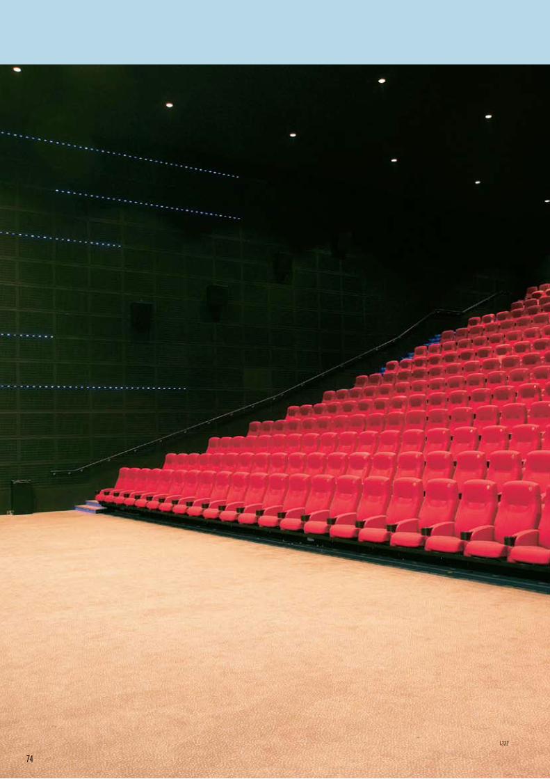
74
1332
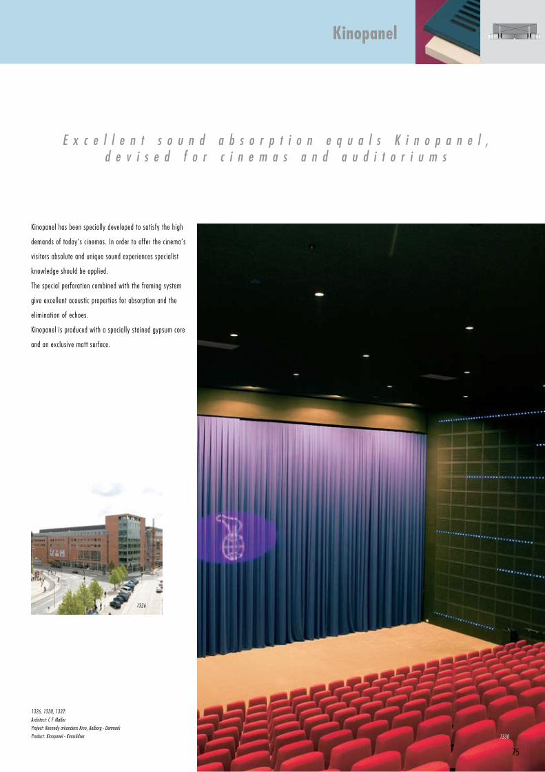
75
Kinopanel has been specially developed to satisfy the high
demands of today’s cinemas. In order to offer the cinema’s
visitors absolute and unique sound experiences specialist
knowledge should be applied.
The special perforation combined with the framing system
give excellent acoustic properties for absorption and the
elimination of echoes.
Kinopanel is produced with a specially stained gypsum core
and an exclusive matt surface.
E x c e l l e n t s o u n d a b s o r p t i o n e q u a l s K i n o p a n e l ,d e v i s e d f o r c i n e m a s a n d a u d i t o r i u m s
1326, 1330, 1332:
Architect: C F Møller
Project: Kennedy arkandens Kino, Aalborg - Denmark
Product: Kinopanel - Kinoslidser
Kinopanel
1330
1326
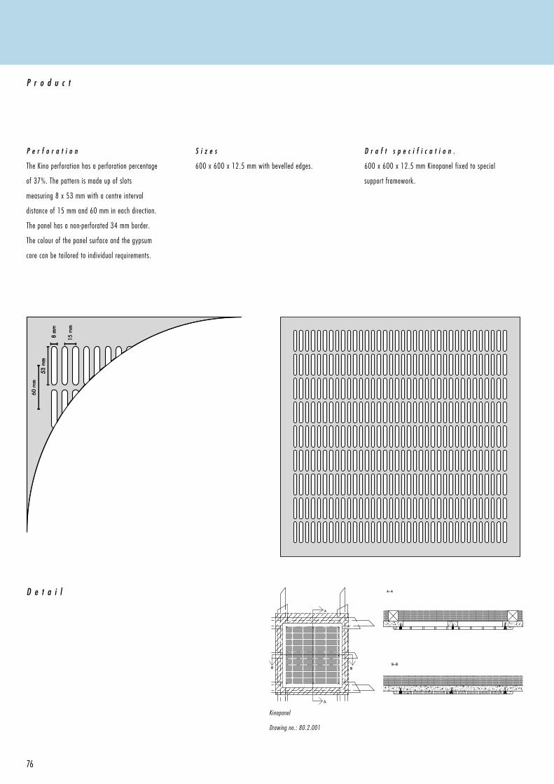
8 m
m
53 m
m
60 m
m
15 m
m
76
Kinopanel
Drawing no.: 80.2.001
D e t a i l
P e r f o r a t i o n
The Kino perforation has a perforation percentage
of 37%. The pattern is made up of slots
measuring 8 x 53 mm with a centre interval
distance of 15 mm and 60 mm in each direction.
The panel has a non-perforated 34 mm border.
The colour of the panel surface and the gypsum
core can be tailored to individual requirements.
P r o d u c t
S i z e s
600 x 600 x 12.5 mm with bevelled edges.
D r a f t s p e c i f i c a t i o n .
600 x 600 x 12.5 mm Kinopanel fixed to special
support framework.
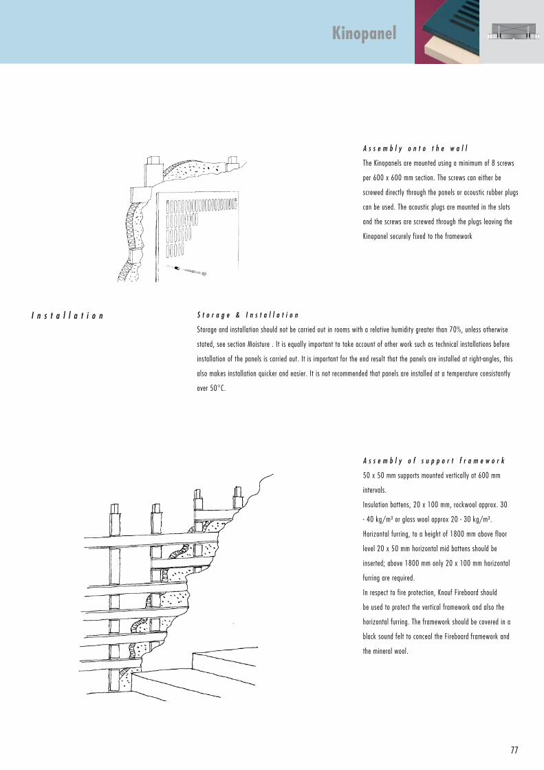
77
A s s e m b l y o f s u p p o r t f r a m e w o r k
50 x 50 mm supports mounted vertically at 600 mm
intervals.
Insulation battens, 20 x 100 mm, rockwool approx. 30
- 40 kg/m³ or glass wool approx 20 - 30 kg/m³.
Horizontal furring, to a height of 1800 mm above floor
level 20 x 50 mm horizontal mid battens should be
inserted; above 1800 mm only 20 x 100 mm horizontal
furring are required.
In respect to fire protection, Knauf Fireboard should
be used to protect the vertical framework and also the
horizontal furring. The framework should be covered in a
black sound felt to conceal the Fireboard framework and
the mineral wool.
S t o r a g e & I n s t a l l a t i o n
Storage and installation should not be carried out in rooms with a relative humidity greater than 70%, unless otherwise
stated, see section Moisture . It is equally important to take account of other work such as technical installations before
installation of the panels is carried out. It is important for the end result that the panels are installed at right-angles, this
also makes installation quicker and easier. It is not recommended that panels are installed at a temperature consistantly
over 50°C.
I n s t a l l a t i o n
A s s e m b l y o n t o t h e w a l l
The Kinopanels are mounted using a minimum of 8 screws
per 600 x 600 mm section. The screws can either be
screwed directly through the panels or acoustic rubber plugs
can be used. The acoustic plugs are mounted in the slots
and the screws are screwed through the plugs leaving the
Kinopanel securely fixed to the framework
Kinopanel
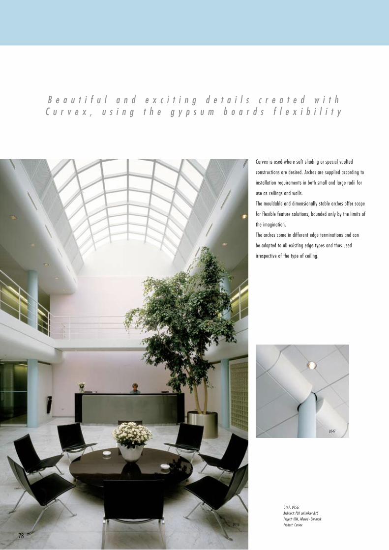
78
Curvex is used where soft shading or special vaulted
constructions are desired. Arches are supplied according to
installation requirements in both small and large radii for
use as ceilings and walls.
The mouldable and dimensionally stable arches offer scope
for flexible feature solutions, bounded only by the limits of
the imagination.
The arches come in different edge terminations and can
be adapted to all existing edge types and thus used
irrespective of the type of ceiling.
B e a u t i f u l a n d e x c i t i n g d e t a i l s c r e a t e d w i t hC u r v e x , u s i n g t h e g y p s u m b o a r d s f l e x i b i l i t y
0147, 0156:
Architect: PLH arkitekter A/S
Project: IBM, Allerød - Denmark
Product: Curvex0156
0147
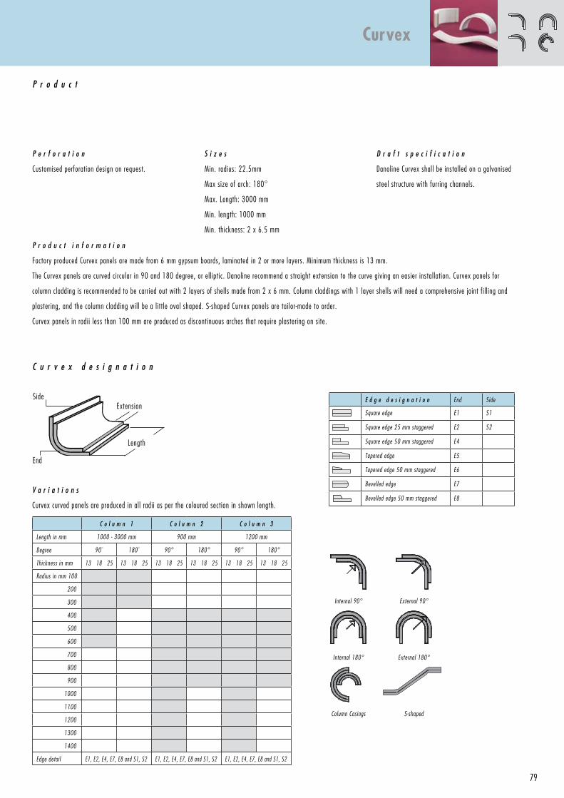
79
E d g e d e s i g n a t i o n End Side
Square edge E1 S1
Square edge 25 mm staggered E2 S2
Square edge 50 mm staggered E4
Tapered edge E5
Tapered edge 50 mm staggered E6
Bevelled edge E7
Bevelled edge 50 mm staggered E8
P r o d u c t i n f o r m a t i o n
Factory produced Curvex panels are made from 6 mm gypsum boards, laminated in 2 or more layers. Minimum thickness is 13 mm.
The Curvex panels are curved circular in 90 and 180 degree, or elliptic. Danoline recommend a straight extension to the curve giving an easier installation. Curvex panels for
column cladding is recommended to be carried out with 2 layers of shells made from 2 x 6 mm. Column claddings with 1 layer shells will need a comprehensive joint fil l ing and
plastering, and the column cladding will be a little oval shaped. S-shaped Curvex panels are tailor-made to order.
Curvex panels in radii less than 100 mm are produced as discontinuous arches that require plastering on site.
V a r i a t i o n s
Curvex curved panels are produced in all radii as per the coloured section in shown length.
C o l u m n 1 C o l u m n 2 C o l u m n 3
Length in mm 1000 - 3000 mm 900 mm 1200 mm
Degree 90° 180° 90° 180° 90° 180°
Thickness in mm 13 18 25 13 18 25 13 18 25 13 18 25 13 18 25 13 18 25
Radius in mm 100
200
300
400
500
600
700
800
900
1000
1100
1200
1300
1400
Edge detail E1, E2, E4, E7, E8 and S1, S2 E1, E2, E4, E7, E8 and S1, S2 E1, E2, E4, E7, E8 and S1, S2
C u r v e x d e s i g n a t i o n
Length
End
SideExtension
P e r f o r a t i o n
Customised perforation design on request.
P r o d u c t
S i z e s
Min. radius: 22.5mm
Max size of arch: 180°
Max. Length: 3000 mm
Min. length: 1000 mm
Min. thickness: 2 x 6.5 mm
D r a f t s p e c i f i c a t i o n
Danoline Curvex shall be installed on a galvanised
steel structure with furring channels.
Internal 90° External 90°
Internal 180° External 180°
Column Casings S-shaped
Curvex
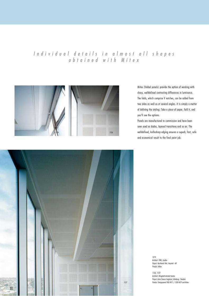
80
Mitex (folded panels) provide the option of working with
sharp, welldefined contrasting differences in luminance.
The folds, which comprise V notches, can be added from
two sides as well as at several angles. It is simply a matter
of defining the styling: Take a piece of paper, fold it, and
you’ll see the options.
Panels are manufactured to commission and have been
seen used as dados, layered transitions and so on. The
welldefined, knifesharp edging ensures a superb, fast, safe
and economical result to the final paint job.
I n d i v i d u a l d e t a i l s i n a l m o s t a l l s h a p e so b t a i n e d w i t h M i t e x
1314:
Architect: YRM, London
Project: Northwick Park, hospital - UK
Product: Mitex
1136, 1137:
Architect: Wingårdh Arkitekt kontor
Project: Astra Zeneca tinghuset, Göteborg - Sweden
Product: Designpanel 900 M1F / 1200 M2F and Mitex1137
11361314
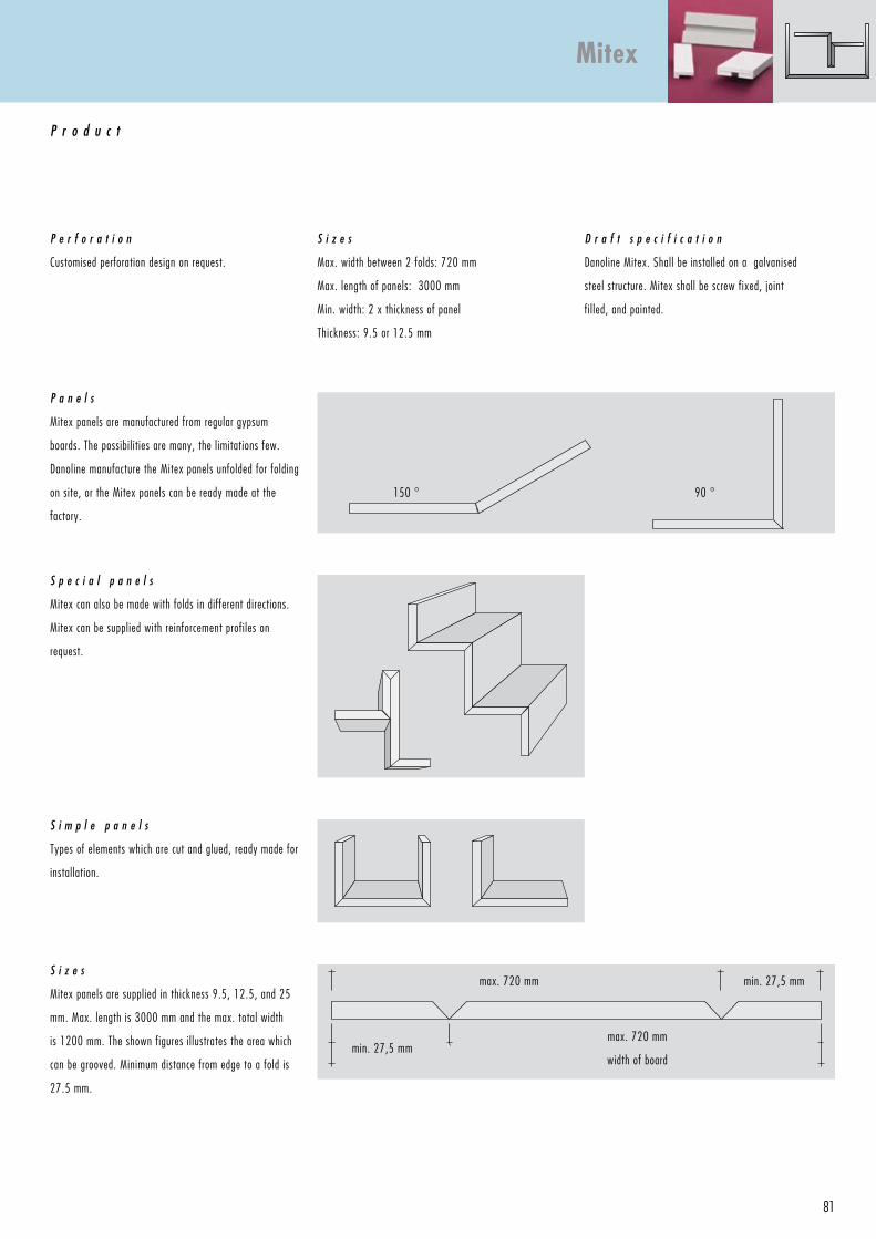
81
P e r f o r a t i o n
Customised perforation design on request.
P r o d u c t
S i z e s
Max. width between 2 folds: 720 mm
Max. length of panels: 3000 mm
Min. width: 2 x thickness of panel
Thickness: 9.5 or 12.5 mm
D r a f t s p e c i f i c a t i o n
Danoline Mitex. Shall be installed on a galvanised
steel structure. Mitex shall be screw fixed, joint
fil led, and painted.
P a n e l s
Mitex panels are manufactured from regular gypsum
boards. The possibilities are many, the limitations few.
Danoline manufacture the Mitex panels unfolded for folding
on site, or the Mitex panels can be ready made at the
factory.
S i z e s
Mitex panels are supplied in thickness 9.5, 12.5, and 25
mm. Max. length is 3000 mm and the max. total width
is 1200 mm. The shown figures illustrates the area which
can be grooved. Minimum distance from edge to a fold is
27.5 mm.
S p e c i a l p a n e l s
Mitex can also be made with folds in different directions.
Mitex can be supplied with reinforcement profiles on
request.
S i m p l e p a n e l s
Types of elements which are cut and glued, ready made for
installation.
max. 720 mm
width of board
min. 27,5 mmmax. 720 mm
min. 27,5 mm
90 °150 °
Mitex
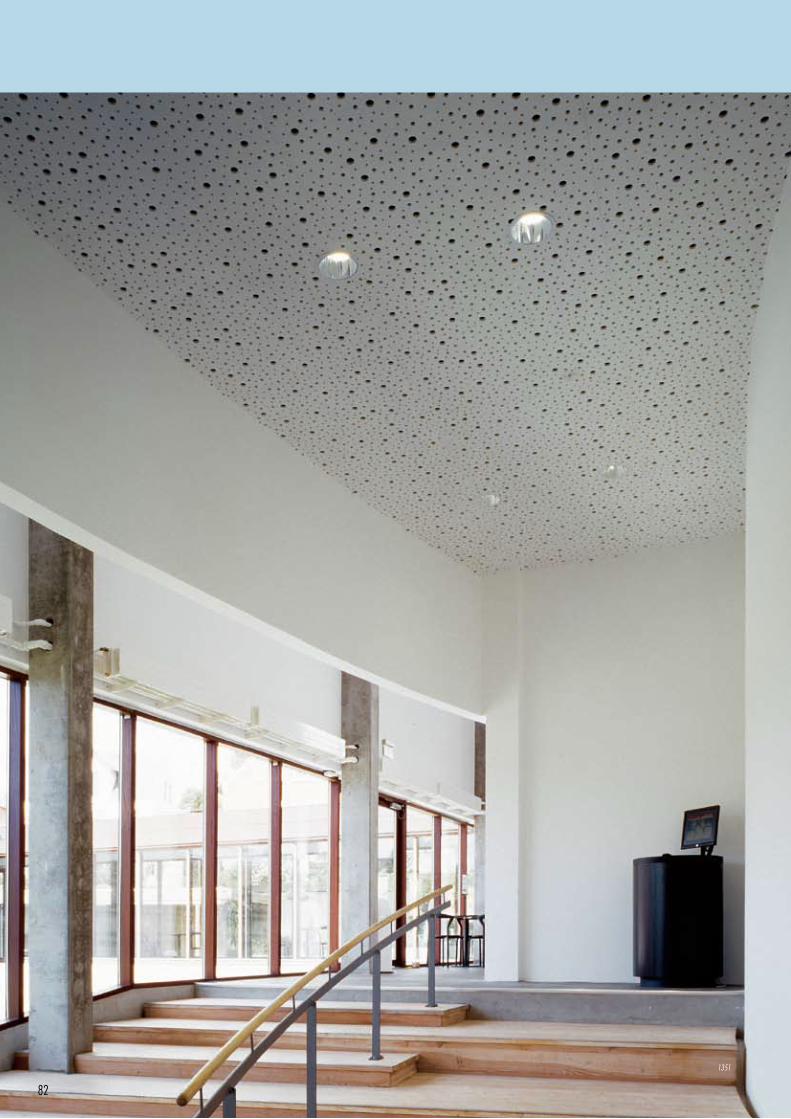
82
1351
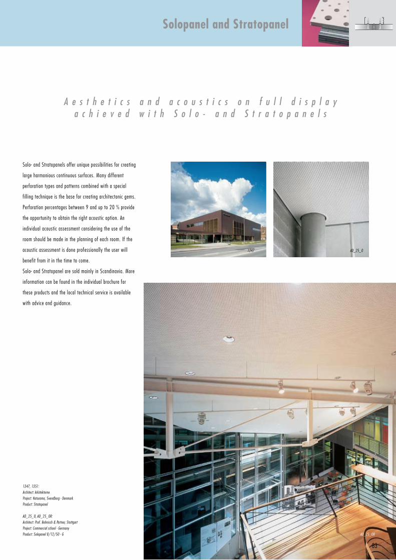
83
A e s t h e t i c s a n d a c o u s t i c s o n f u l l d i s p l a ya c h i e v e d w i t h S o l o - a n d S t r a t o p a n e l s
Solo- and Stratopanels offer unique possibilities for creating
large harmonious continuous surfaces. Many different
perforation types and patterns combined with a special
fil l ing technique is the base for creating architectonic gems.
Perforation percentages between 9 and up to 20 % provide
the opportunity to obtain the right acoustic option. An
individual acoustic assessment considering the use of the
room should be made in the planning of each room. If the
acoustic assessment is done professionally the user will
benefit from it in the time to come.
Solo- and Stratopanel are sold mainly in Scandinavia. More
information can be found in the individual brochure for
these products and the local technical service is available
with advice and guidance.
1347, 1351:
Architect: Arkitekterne
Project: Naturama, Svendborg - Denmark
Product: Stratopanel
AD_25_O, AD_25_OR:
Architect: Prof. Behnisch & Partner, Stuttgart
Project: Commercial school - Germany
Product: Solopanel 8/12/50 - G
Solopanel and Stratopanel
1347 AD_25_O
AD_25_OR
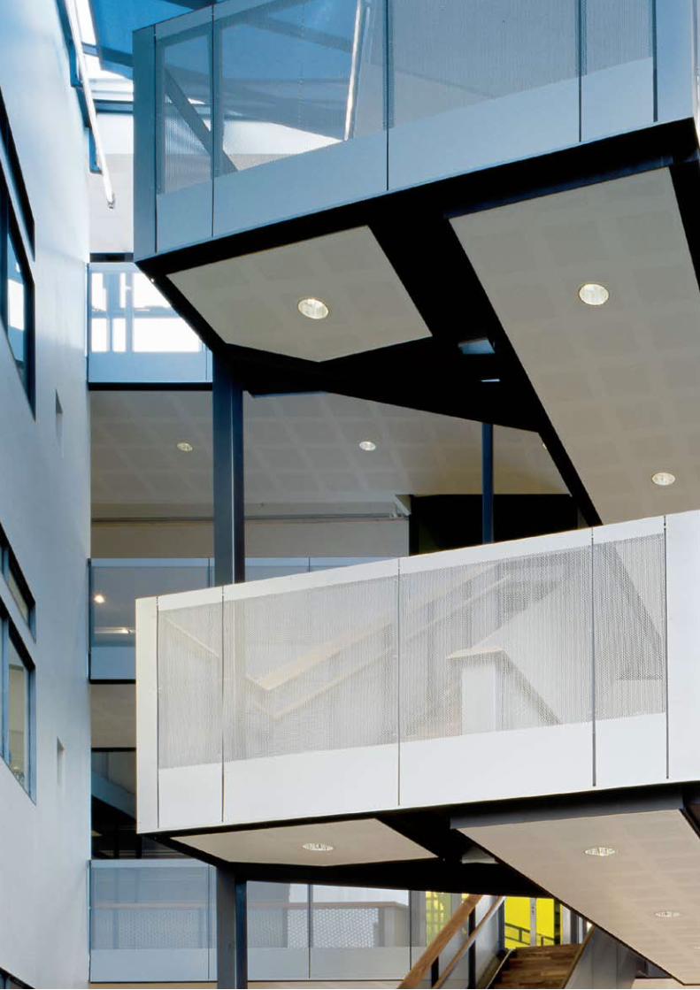
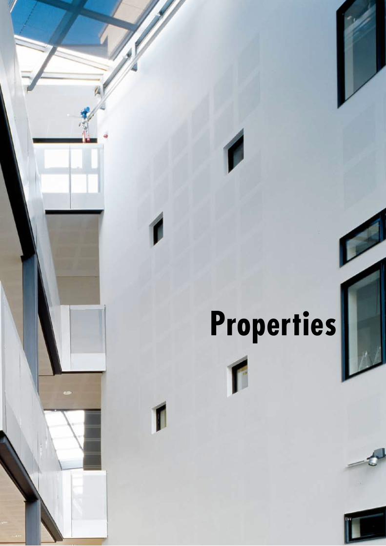
Properties
1144
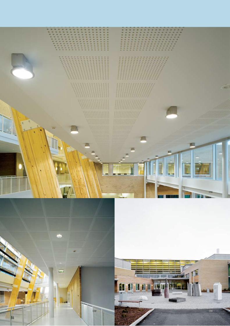
86
12451248
1246
87
Surfacing - gypsum as a natural palette page 88
Acoustics - gypsum regulates sound page 90
Fire - gypsum as nature’s sprinkler page 98
Indoor climate and environment - gypsum can breathe page 100
Load-bearing capacity and weight - gypsum as a weightlifter page 102
Moisture - gypsum as a natural skin page 104
Luminous reflectance - gypsum mirrors light page 106
1144:
Architect: Liljewall Arkitekter Göteborg
Project: Biotechhuset, Göteborg - Sweden
Product: Designpanel 1200 - M2F
1245, 1246:
Architect: Link Arkitekter, Oslo
Project: Nannestad skole - Norway
Product: Designpanel 1200 - Q2F
1248:
Architect: Link Arkitekter, Oslo
Project: Nannestad skole - Norway
Product: Plaza 600 - M1
Properties
E v e n t h e b e s t r a w m a t e r i a l c a n b ee n h a n c e d f o r f u r t h e r v a l u e
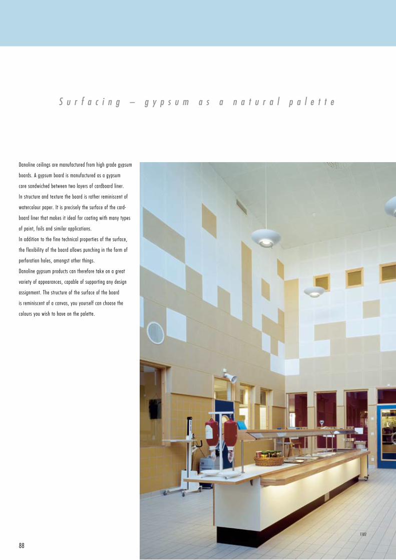
88
S u r f a c i n g – g y p s u m a s a n a t u r a l p a l e t t e
Danoline ceilings are manufactured from high grade gypsum
boards. A gypsum board is manufac tured as a gypsum
core sandwiched between two layers of cardboard liner.
In structure and texture the board is rather reminiscent of
watercolour paper. It is precisely the surface of the card-
board liner that makes it ideal for coating with many types
of paint, foils and similar applica tions.
In addition to the fine technical properties of the surface,
the flexibility of the board allows punching in the form of
perforation holes, amongst other things.
Danoline gypsum products can therefore take on a great
variety of appearances, capable of supporting any design
assignment. The structure of the surface of the board
is reminiscent of a canvas, you yourself can choose the
colours you wish to have on the palette.
1183
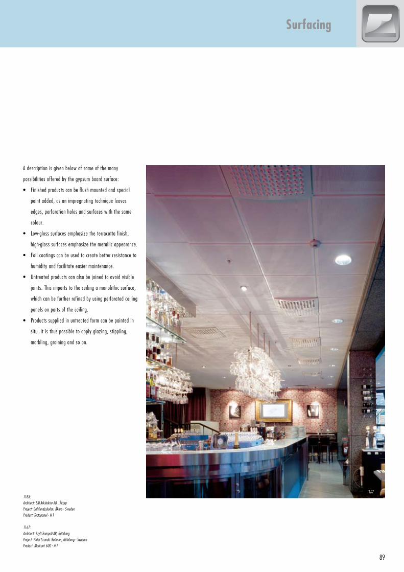
89
A description is given below of some of the many
possibilities offered by the gypsum board surface:
• Finishedproductscanbeflushmountedandspecial
paint added, as an impregnating technique leaves
edges, perforation holes and surfaces with the same
colour.
• Low-glosssurfacesemphasizetheterracottafinish,
high-glosssurfacesemphasizethemetallicappearance.
• Foilcoatingscanbeusedtocreatebetterresistanceto
humidity and facilitate easier maintenance.
• Untreatedproductscanalsobejoinedtoavoidvisible
joints.Thisimpartstotheceilingamonolithicsurface,
which can be further refined by using perforated ceiling
panels on parts of the ceiling.
• Productssuppliedinuntreatedformcanbepaintedin
situ.Itisthuspossibletoapplyglazing,stippling,
marbling, graining and so on.
1183:
Architect: BM Arkitekter AB , Åkarp
Project: Dalslundsskolan, Åkarp - Sweden
Product: Tectopanel - M1
1167:
Architect: Stylt Trampoli AB, Göteborg
Project: Hotel Scandic Rubinen, Göteborg - Sweden
Product: Markant 600 - M1
Surfacing
1167
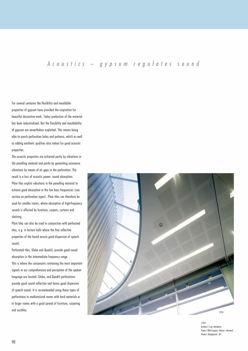
90
For several centuries the flexibility and mouldable
properties of gypsum have provided the inspiration for
beautiful decorative work. Today production of the material
has been industrialised. But the flexibility and mouldability
of gypsum are nevertheless exploited. This means being
able to punch perforation holes and patterns, which as well
as adding aesthetic qualities also makes for good acoustic
properties.
The acoustic properties are achieved partly by vibrations in
the panelling material and partly by generating resonance
vibrations by means of air gaps in the perforation. The
result is a loss of acoustic power: sound absorption.
Plaintilesexploitvibrationsinthepanellingmaterialto
achieve good absorption in the low bass frequencies (see
sectiononperforationtypes).Plaintilescanthereforebe
used for smaller rooms, where absorption of high-frequency
sounds is effected by furniture, carpets, curtains and
shelving.
Plaintilescanalsobeusedinconjunctionwithperforated
tiles, e.g. in lecture halls where the fine reflective
properties of the board ensure good dispersion of speech
sound.
Perforatedtiles,GlobeandQuadril,providegoodsound
absorption in the intermediate frequency range.
This is where the consonants containing the most important
signals in our comprehension and perception of the spoken
languagearelocated.Globe,andQuadrilperforations
provide good sound reflection and hence good dispersion
of speech sound. It is recommended using these types of
perforationsinmediumsizedroomswithhardmaterialsor
in larger rooms with a good spread of furniture, carpeting
and suchlike.
A c o u s t i c s – g y p s u m r e g u l a t e s s o u n d
1294:
Architect: S og I Arkitekter
Project: OBH Gruppen, Odense - Denmark
Product: Designpanel - M1
1294
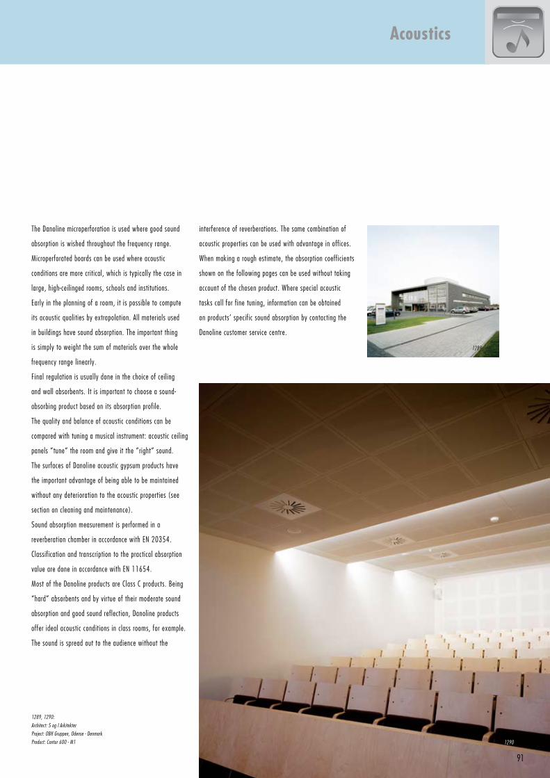
91
The Danoline microperforation is used where good sound
absorption is wished throughout the frequency range.
Microperforated boards can be used where acoustic
conditions are more critical, which is typically the case in
large, high-ceilinged rooms, schools and institutions.
Early in the planning of a room, it is possible to compute
its acoustic qualities by extrapolation. All materials used
in buildings have sound absorption. The important thing
is simply to weight the sum of materials over the whole
frequency range linearly.
Final regulation is usually done in the choice of ceiling
and wall absorbents. It is important to choose a sound-
absorbing product based on its absorption profile.
The quality and balance of acoustic conditions can be
compared with tuning a musical instrument: acoustic ceiling
panels ”tune” the room and give it the ”right” sound.
The surfaces of Danoline acoustic gypsum products have
the important advantage of being able to be maintained
without any deterioration to the acoustic properties (see
section on cleaning and maintenance).
Sound absorption measurement is performed in a
reverberation chamber in accordance with EN 20354.
Classification and transcription to the practical absorption
value are done in accordance with EN 11654.
Most of the Danoline products are Class C products. Being
“hard” absorbents and by virtue of their moderate sound
absorption and good sound reflection, Danoline products
offer ideal acoustic conditions in class rooms, for example.
The sound is spread out to the audience without the
1289, 1290:
Architect: S og I Arkitekter
Project: OBH Gruppen, Odense - Denmark
Product: Contur 600 - M1
Acoustics
interference of reverberations. The same combination of
acoustic properties can be used with advantage in offices.
When making a rough estimate, the absorption coefficients
shown on the following pages can be used without taking
account of the chosen product. Where special acoustic
tasks call for fine tuning, information can be obtained
on products’ specific sound absorption by contacting the
Danoline customer service centre.
1289
1290
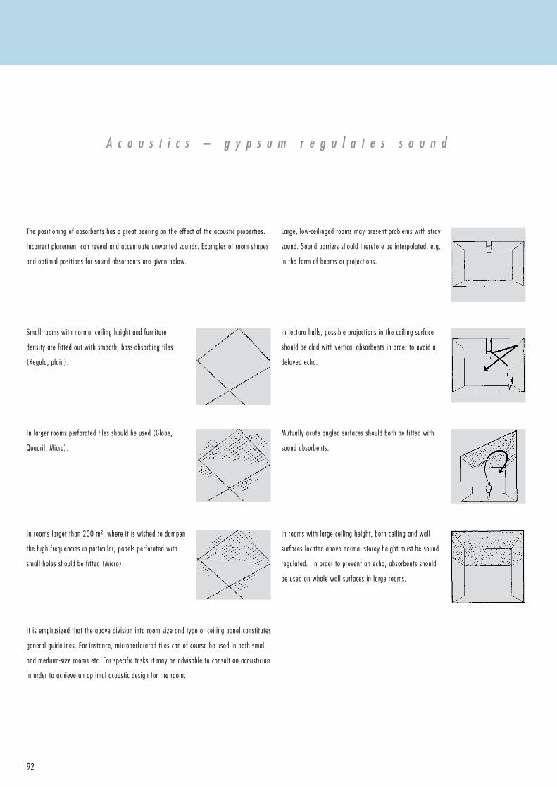
92
The positioning of absorbents has a great bearing on the effect of the acoustic properties.
Incorrect placement can reveal and accentuate unwanted sounds. Examples of room shapes
and optimal positions for sound absorbents are given below.
Small rooms with normal ceiling height and furniture
density are fitted out with smooth, bass-absorbing tiles
(Regula, plain).
In rooms larger than 200 m², where it is wished to dampen
the high frequencies in particular, panels perforated with
small holes should be fitted (Micro).
Itisemphasizedthattheabovedivisionintoroomsizeandtypeofceilingpanelconstitutes
general guidelines. For instance, microperforated tiles can of course be used in both small
andmedium-sizeroomsetc.Forspecifictasksitmaybeadvisabletoconsultanacoustician
in order to achieve an optimal acoustic design for the room.
Inlargerroomsperforatedtilesshouldbeused(Globe,
Quadril,Micro).
Large, low-ceilinged rooms may present problems with stray
sound. Sound barriers should therefore be interpolated, e.g.
intheformofbeamsorprojections.
In rooms with large ceiling height, both ceiling and wall
surfaces located above normal storey height must be sound
regulated. In order to prevent an echo, absorbents should
be used on whole wall surfaces in large rooms.
Inlecturehalls,possibleprojectionsintheceilingsurface
should be clad with vertical absorbents in order to avoid a
delayed echo.
Mutually acute angled surfaces should both be fitted with
sound absorbents.
A c o u s t i c s – g y p s u m r e g u l a t e s s o u n d
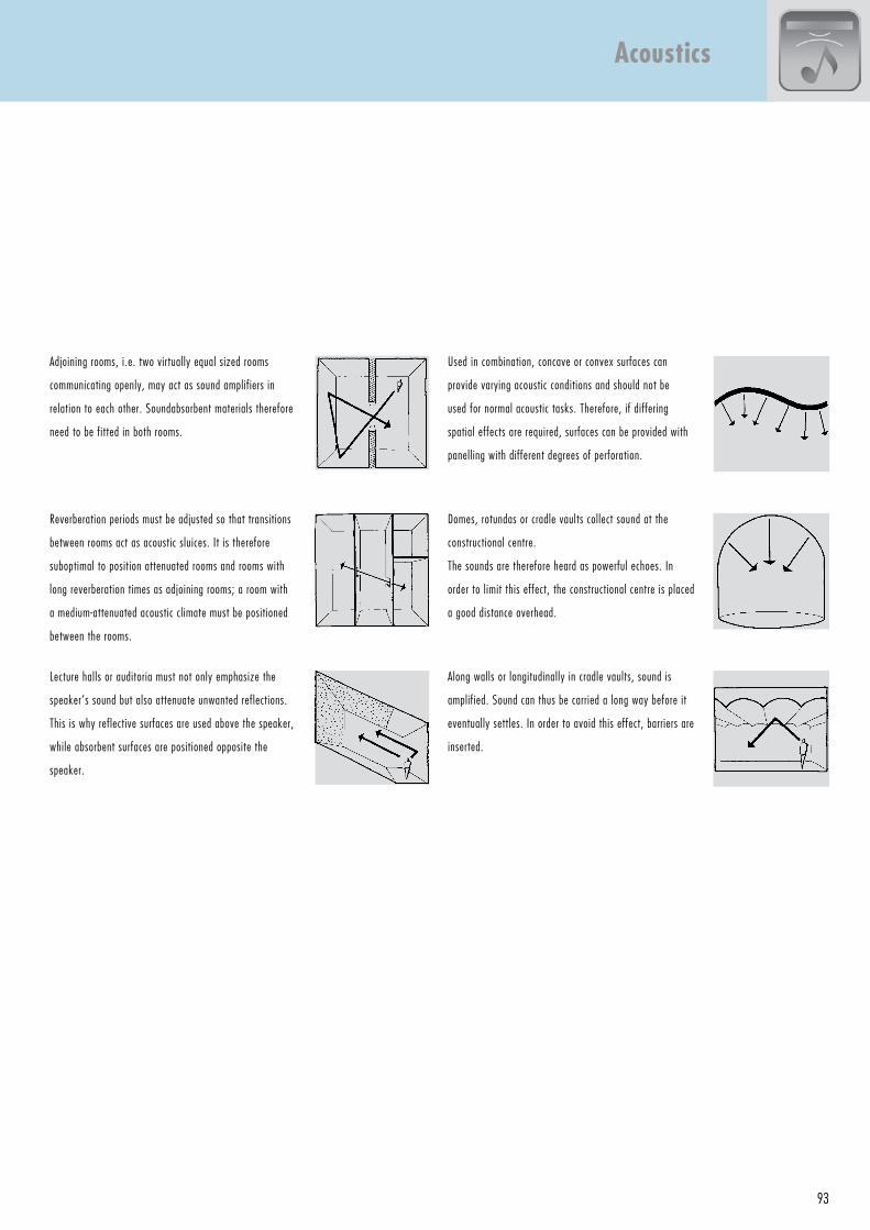
93
Lecturehallsorauditoriamustnotonlyemphasizethe
speaker’s sound but also attenuate unwanted reflections.
This is why reflective surfaces are used above the speaker,
while absorbent surfaces are positioned opposite the
speaker.
Adjoiningrooms,i.e.twovirtuallyequalsizedrooms
communicating openly, may act as sound amplifiers in
relation to each other. Soundabsorbent materials therefore
need to be fitted in both rooms.
Reverberationperiodsmustbeadjustedsothattransitions
between rooms act as acoustic sluices. It is therefore
suboptimal to position attenuated rooms and rooms with
longreverberationtimesasadjoiningrooms;aroomwith
a medium-attenuated acoustic climate must be positioned
between the rooms.
Usedincombination,concaveorconvexsurfacescan
provide varying acoustic conditions and should not be
used for normal acoustic tasks. Therefore, if differing
spatial effects are required, surfaces can be provided with
panelling with different degrees of perforation.
Domes, rotundas or cradle vaults collect sound at the
constructional centre.
The sounds are therefore heard as powerful echoes. In
order to limit this effect, the constructional centre is placed
a good distance overhead.
Along walls or longitudinally in cradle vaults, sound is
amplified. Sound can thus be carried a long way before it
eventually settles. In order to avoid this effect, barriers are
inserted.
Acoustics
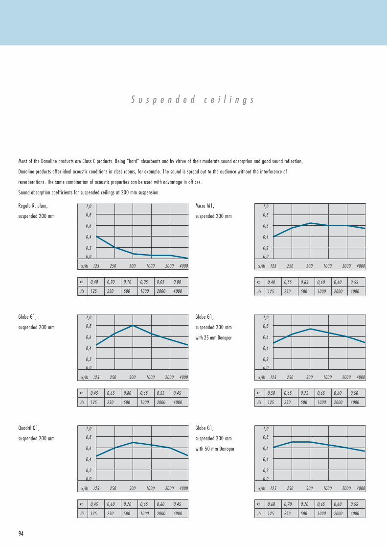
α 0,40 0,20 0,10 0,05 0,05 0,00
Hz 125 250 500 1000 2000 4000
1,0
0,8
0,6
0,4
0,2
0,0
α/Hz 125 250 500 1000 2000 4000
α 0,45 0,60 0,70 0,65 0,60 0,45
Hz 125 250 500 1000 2000 4000
1,0
0,8
0,6
0,4
0,2
0,0
α/Hz 125 250 500 1000 2000 4000
α 0,45 0,65 0,80 0,65 0,55 0,45
Hz 125 250 500 1000 2000 4000
1,0
0,8
0,6
0,4
0,2
0,0
α/Hz 125 250 500 1000 2000 4000
α 0,40 0,55 0,65 0,60 0,60 0,55
Hz 125 250 500 1000 2000 4000
1,0
0,8
0,6
0,4
0,2
0,0
α/Hz 125 250 500 1000 2000 4000
α 0,60 0,70 0,70 0,65 0,60 0,55
Hz 125 250 500 1000 2000 4000
1,0
0,8
0,6
0,4
0,2
0,0
α/Hz 125 250 500 1000 2000 4000
α 0,50 0,65 0,75 0,65 0,60 0,50
Hz 125 250 500 1000 2000 4000
1,0
0,8
0,6
0,4
0,2
0,0
α/Hz 125 250 500 1000 2000 4000
94
Most of the Danoline products are Class C products. Being “hard” absorbents and by virtue of their moderate sound absorption and good sound reflection,
Danoline products offer ideal acoustic conditions in class rooms, for example. The sound is spread out to the audience without the interference of
reverberations. The same combination of acoustic properties can be used with advantage in offices.
Sound absorption coefficients for suspended ceilings at 200 mm suspension.
Regula R, plain,
suspended 200 mm
Micro M1,
suspended 200 mm
GlobeG1,
suspended 200 mm
QuadrilQ1,
suspended 200 mm
GlobeG1,
suspended 200 mm
with 25 mm Danopor
GlobeG1,
suspended 200 mm
with 50 mm Danopor
S u s p e n d e d c e i l i n g s
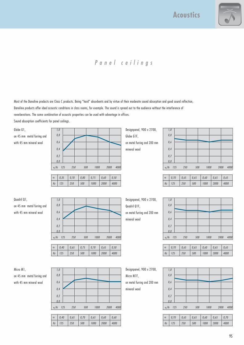
1,0
0,8
0,6
0,4
0,2
0,0
α/Hz 125 250 500 1000 2000 4000
α 0,35 0,70 0,80 0,75 0,60 0,50
Hz 125 250 500 1000 2000 4000
α 0,40 0,65 0,75 0,70 0,65 0,50
Hz 125 250 500 1000 2000 4000
1,0
0,8
0,6
0,4
0,2
0,0
α/Hz 125 250 500 1000 2000 4000
α 0,40 0,65 0,70 0,65 0,60 0,60
Hz 125 250 500 1000 2000 4000
1,0
0,8
0,6
0,4
0,2
0,0
α/Hz 125 250 500 1000 2000 4000
α 0,70 0,65 0,65 0,60 0,65 0,65
Hz 125 250 500 1000 2000 4000
1,0
0,8
0,6
0,4
0,2
0,0
α/Hz 125 250 500 1000 2000 4000
α 0,70 0,65 0,65 0,60 0,65 0,65
Hz 125 250 500 1000 2000 4000
1,0
0,8
0,6
0,4
0,2
0,0
α/Hz 125 250 500 1000 2000 4000
α 0,70 0,65 0,65 0,60 0,65 0,70
Hz 125 250 500 1000 2000 4000
1,0
0,8
0,6
0,4
0,2
0,0
α/Hz 125 250 500 1000 2000 4000
95
P a n e l c e i l i n g s
Most of the Danoline products are Class C products. Being “hard” absorbents and by virtue of their moderate sound absorption and good sound reflection,
Danoline products offer ideal acoustic conditions in class rooms, for example. The sound is spread out to the audience without the interference of
reverberations. The same combination of acoustic properties can be used with advantage in offices.
Sound absorption coefficients for panel ceilings.
Micro M1,
on 45 mm metal furring and
with 45 mm mineral wool
QuadrilQ1,
on 45 mm metal furring and
with 45 mm mineral wool
GlobeG1,
on 45 mm metal furring and
with 45 mm mineral wool
Designpanel, 900 x 2700,
GlobeG1F,
on metal furring and 200 mm
mineral wool
Designpanel, 900 x 2700,
Micro M1F,
on metal furring and 200 mm
mineral wool
Designpanel, 900 x 2700,
QuadrilQ1F,
on metal furring and 200 mm
mineral wool
Acoustics
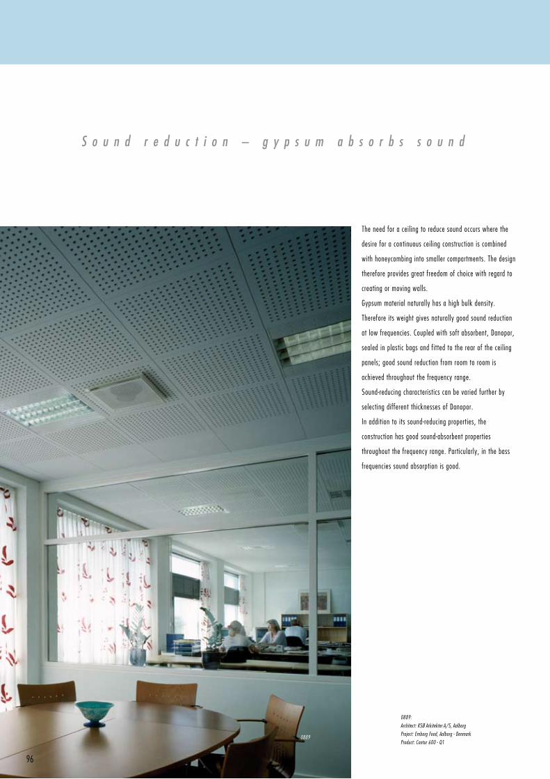
96
The need for a ceiling to reduce sound occurs where the
desire for a continuous ceiling construction is combined
with honeycombing into smaller compartments. The design
therefore provides great freedom of choice with regard to
creating or moving walls.
Gypsummaterialnaturallyhasahighbulkdensity.
Therefore its weight gives naturally good sound reduction
at low frequencies. Coupled with soft absorbent, Danopor,
sealed in plastic bags and fitted to the rear of the ceiling
panels;goodsoundreductionfromroomtoroomis
achieved throughout the frequency range.
Sound-reducing characteristics can be varied further by
selecting different thicknesses of Danopor.
In addition to its sound-reducing properties, the
construction has good sound-absorbent properties
throughoutthefrequencyrange.Particularly,inthebass
frequencies sound absorption is good.
S o u n d r e d u c t i o n – g y p s u m a b s o r b s s o u n d
0889:
Architect: KSØ Arkitekter A/S, Aalborg
Project: Emborg Food, Aalborg - Denmark
Product: Contur 600 - Q10889
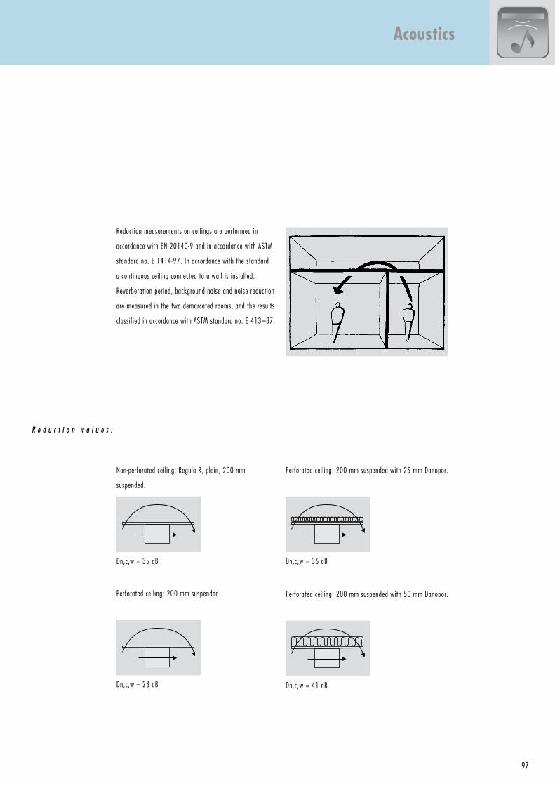
97
Reduction measurements on ceilings are performed in
accordance with EN 20140-9 and in accordance with ASTM
standard no. E 1414-97. In accordance with the standard
a continuous ceiling connected to a wall is installed.
Reverberation period, background noise and noise reduction
are measured in the two demarcated rooms, and the results
classified in accordance with ASTM standard no. E 413–87.
R e d u c t i o n v a l u e s :
Dn,c,w = 36 dB
Dn,c,w = 41 dB
Dn,c,w = 35 dB
Dn,c,w = 23 dB
Acoustics
Perforatedceiling:200mmsuspendedwith25mmDanopor.
Perforatedceiling:200mmsuspendedwith50mmDanopor.
Non-perforated ceiling: Regula R, plain, 200 mm
suspended.
Perforatedceiling:200mmsuspended.
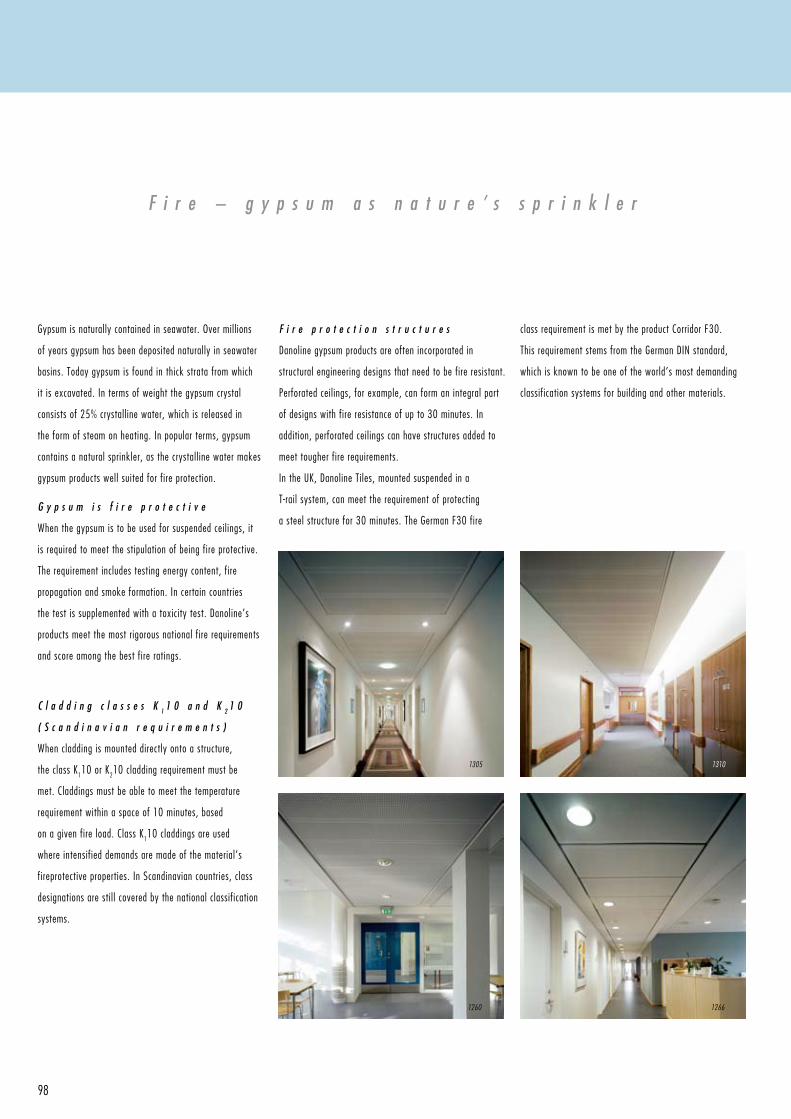
98
F i r e – g y p s u m a s n a t u r e ’ s s p r i n k l e r
Gypsumisnaturallycontainedinseawater.Overmillions
of years gypsum has been deposited naturally in seawater
basins. Today gypsum is found in thick strata from which
it is excavated. In terms of weight the gypsum crystal
consists of 25% crystalline water, which is released in
the form of steam on heating. In popular terms, gypsum
contains a natural sprinkler, as the crystalline water makes
gypsum products well suited for fire protection.
G y p s u m i s f i r e p r o t e c t i v e
When the gypsum is to be used for suspended ceilings, it
is required to meet the stipulation of being fire protective.
The requirement includes testing energy content, fire
propagation and smoke formation. In certain countries
the test is supplemented with a toxicity test. Danoline’s
products meet the most rigorous national fire requirements
and score among the best fire ratings.
C l a d d i n g c l a s s e s K 1 1 0 a n d K 2 1 0
( S c a n d i n a v i a n r e q u i r e m e n t s )
When cladding is mounted directly onto a structure,
the class K110 or K210 cladding requirement must be
met. Claddings must be able to meet the temperature
requirement within a space of 10 minutes, based
on a given fire load. Class K110 claddings are used
where intensified demands are made of the material’s
fireprotective properties. In Scandinavian countries, class
designations are stil l covered by the national classification
systems.
F i r e p r o t e c t i o n s t r u c t u r e s
Danoline gypsum products are often incorporated in
structural engineering designs that need to be fire resistant.
Perforatedceilings,forexample,canformanintegralpart
of designs with fire resistance of up to 30 minutes. In
addition, perforated ceilings can have structures added to
meet tougher fire requirements.
IntheUK,DanolineTiles,mountedsuspendedina
T-rail system, can meet the requirement of protecting
asteelstructurefor30minutes.TheGermanF30fire
class requirement is met by the product Corridor F30.
ThisrequirementstemsfromtheGermanDINstandard,
which is known to be one of the world’s most demanding
classification systems for building and other materials.
12661260
13101305
99
1305:
Architect: Aukett Ltd, SW11.
Project: SAS Radisson, Stansted - UK
Product: Designpanel - M1F
1310:
Architect: YRM, London, EC1.
Project: Northwick Park Hospital - UK
Product: Corridor 300 - M1
1260:
Architect: Tage Nielsens tegnestue
Project: RUC Bygn 02, Roskilde - Denmark
Product: Corridor 300 - G1
1266:
Architect: Arkitektgruppen Aarhus
Project: Greve Rådhus - Denmark
Product: Corridor Swing - M1
E u r o p e
Material class A2-s1, d0 covers following products:
Contur,Markant,Linear,Plaza,Belgravia,Tectopanel,
Danopanel, Designpanel.
Material class B-s1, d0 covers following products:
Corridor, Combipanels, Danoline tiles, Contrapanel, Kwik-up.
U K
Non-combustible materials, BS 476, part 4, 1970,
Warrington,Warresno.45918.FirePropagationBS
476, part 6, 1981, Warrington, Warres no. 45916, no.
45917. Surface Spread of Flame: BS 476, part 7, 1971,
Warrington, Warres no. 45912, no. 45913, no. 45914,
no.45915.IncludesPlaza,Markant,Contur,Corridor.
½ Hour Fire Rated, BS 476, part 23, 1987. (Clause 5
SuspendedCeilingAssemblyProtectingLoadbearing
I-SectionSteelBeams).EffectiveProtection40min.
Includes Danoline Tiles.
R e l e v a n t c l a s s i f i c a t i o n s a r e r e v i e w e d b e l o w . ( P l e a s e a l s o r e f e r t o p a g e s 1 2 2 - 1 2 7 ) .
Fire
G e r m a n y
Baustoffklassenichtbrennbar,DIN4102-1,05/98.P-MPA-
E-01-656.Includesallproducts13mmthick,e.g.Plaza,
Markant, Belgravia, Contur, Linear.
Baustoffklasse schwer entflammbar B1, DIN 4102. Includes
products 12.5 mm thick, e.g. Danotile and Combipanel.
F-30A.Unterdeckeallein.Brandbeanspruchungvon
oben(Zwischendeckenbereich)undUnterdeckeallein
Brandbeanspruchung von unten (Deckenunterseite).
Feuerwiderstandsklasse F30 gem. DIN 4102 ,Teil 2, Ausgabe
09/1977. Includes Corridor F30.
F i n l a n d
Construction and ignitability class REI 30. Test report no.
YM275/6221/2003. Covers Danopanel, Tectopanel,
Designpanel
S w e d e n
Tändskyddande beklädnad: Tectopanel SITAC nr 2979/80,
Combipanel SITAC nr 2981/80, Markant 600 (600 x 600
mm,min.200mmnedpendlat)ochPlaza600(9,5x600
x600mmförperforeringGlobe,Microoch12,5x600x
600mmförperforeringQuadril,min.200mmnedpendlat)
SITAC nr 0054/02. Byggnadsdel: Danoline undertak EI30
(Tecto-, Design- och Danopanel) SITAC nr 0612/01.
N o r w a y
K1-A ln 1. Sertificeringslicens nr. 544. covers following
products: Tectopanel, Designpanel 900, Combipanel,
Danopanel,Plaza,Markant,Contur,Linear,Belgraviaand
Corridor.
D e n m a r k
Klasse 1 beklædning, MK 6.31/0426. covers following
products:Tectopanel,Designpanel,Combipanel,PindOp,
Danopanel.
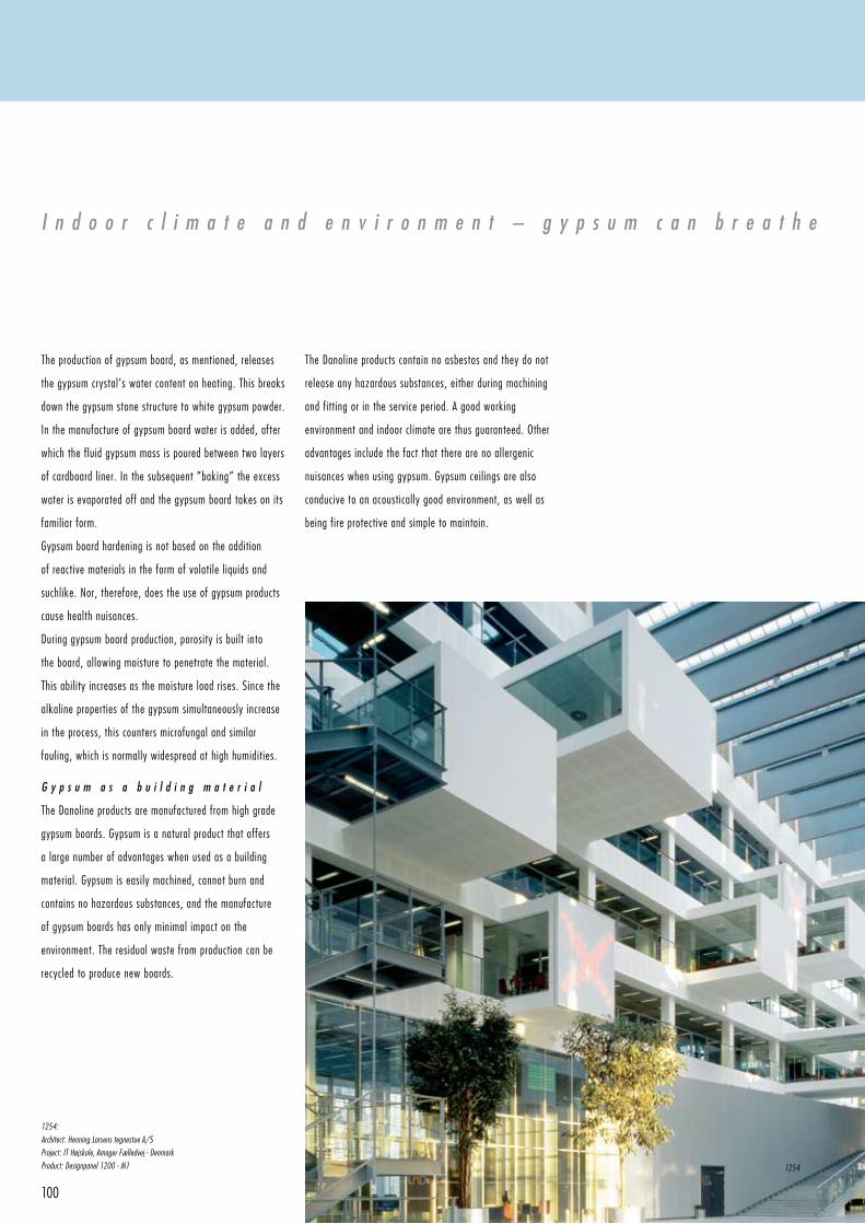
100
I n d o o r c l i m a t e a n d e n v i r o n m e n t – g y p s u m c a n b r e a t h e
The production of gypsum board, as mentioned, releases
the gypsum crystal’s water content on heating. This breaks
down the gypsum stone structure to white gypsum powder.
In the manufacture of gypsum board water is added, after
which the fluid gypsum mass is poured between two layers
of cardboard liner. In the subsequent ”baking” the excess
water is evaporated off and the gypsum board takes on its
familiar form.
Gypsumboardhardeningisnotbasedontheaddition
of reactive materials in the form of volatile liquids and
suchlike. Nor, therefore, does the use of gypsum products
cause health nuisances.
During gypsum board production, porosity is built into
the board, allowing moisture to penetrate the material.
This ability increases as the moisture load rises. Since the
alkaline properties of the gypsum simultaneously increase
in the process, this counters microfungal and similar
fouling, which is normally widespread at high humidities.
G y p s u m a s a b u i l d i n g m a t e r i a l
The Danoline products are manufactured from high grade
gypsumboards.Gypsumisanaturalproductthatoffers
a large number of advantages when used as a building
material.Gypsumiseasilymachined,cannotburnand
containsnohazardoussubstances,andthemanufacture
of gypsum boards has only minimal impact on the
environment. The residual waste from production can be
recycled to produce new boards.
The Danoline products contain no asbestos and they do not
releaseanyhazardoussubstances,eitherduringmachining
and fitting or in the service period. A good working
environmentandindoorclimatearethusguaranteed.Other
advantages include the fact that there are no allergenic
nuisanceswhenusinggypsum.Gypsumceilingsarealso
conducive to an acoustically good environment, as well as
being fire protective and simple to maintain.
1254:
Architect: Henning Larsens tegnestue A/S
Project: IT Højskole, Amager Fælledvej - Denmark
Product: Designpanel 1200 - M1 1254
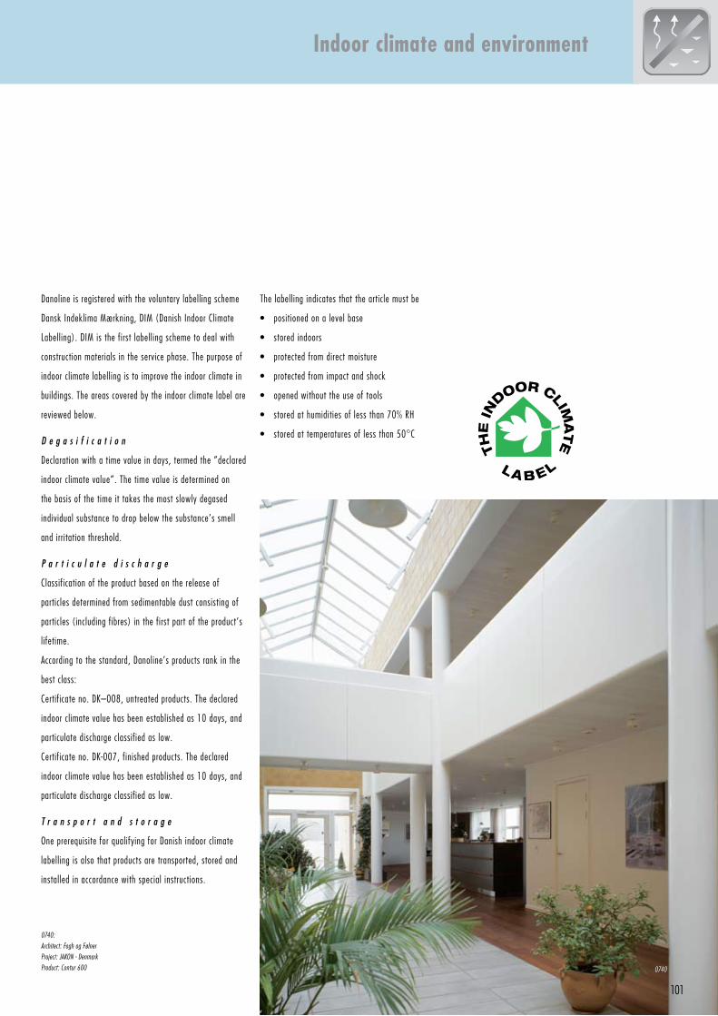
101
Danoline is registered with the voluntary labelling scheme
Dansk Indeklima Mærkning, DIM (Danish Indoor Climate
Labelling). DIM is the first labelling scheme to deal with
construction materials in the service phase. The purpose of
indoor climate labelling is to improve the indoor climate in
buildings. The areas covered by the indoor climate label are
reviewed below.
D e g a s i f i c a t i o n
Declaration with a time value in days, termed the ”declared
indoor climate value”. The time value is determined on
the basis of the time it takes the most slowly degased
individual substance to drop below the substance’s smell
and irritation threshold.
P a r t i c u l a t e d i s c h a r g e
Classification of the product based on the release of
particles determined from sedimentable dust consisting of
particles (including fibres) in the first part of the product’s
lifetime.
According to the standard, Danoline’s products rank in the
best class:
Certificate no. DK–008, untreated products. The declared
indoor climate value has been established as 10 days, and
particulate discharge classified as low.
Certificate no. DK-007, finished products. The declared
indoor climate value has been established as 10 days, and
particulate discharge classified as low.
T r a n s p o r t a n d s t o r a g e
OneprerequisiteforqualifyingforDanishindoorclimate
labelling is also that products are transported, stored and
installed in accordance with special instructions.
0740:
Architect: Fogh og Følner
Project: JAKON - Denmark
Product: Contur 600
Indoor climate and environment
The labelling indicates that the article must be
• positionedonalevelbase
• storedindoors
• protectedfromdirectmoisture
• protectedfromimpactandshock
• openedwithouttheuseoftools
• storedathumiditiesoflessthan70%RH
• storedattemperaturesoflessthan50°C
0740
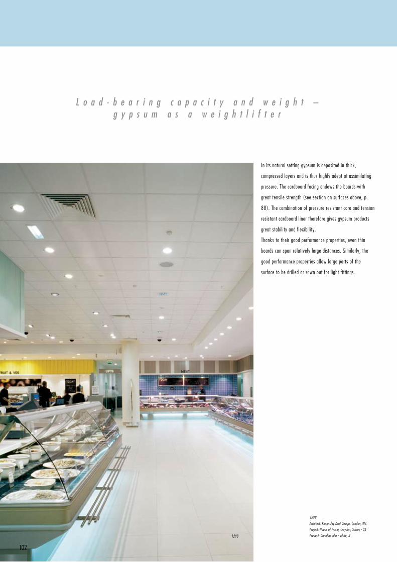
102
L o a d - b e a r i n g c a p a c i t y a n d w e i g h t –g y p s u m a s a w e i g h t l i f t e r
In its natural setting gypsum is deposited in thick,
compressed layers and is thus highly adept at assimilating
pressure. The cardboard facing endows the boards with
great tensile strength (see section on surfaces above, p.
88). The combination of pressure resistant core and tension
resistant cardboard liner therefore gives gypsum products
great stability and flexibility.
Thanks to their good performance properties, even thin
boards can span relatively large distances. Similarly, the
good performance properties allow large parts of the
surface to be drilled or sawn out for light fittings.
1298:
Architect: Kinnersley Kent Design, London, W1.
Project: House of Fraser, Croydon, Surrey - UK
Product: Danoline tiles - white, R1298
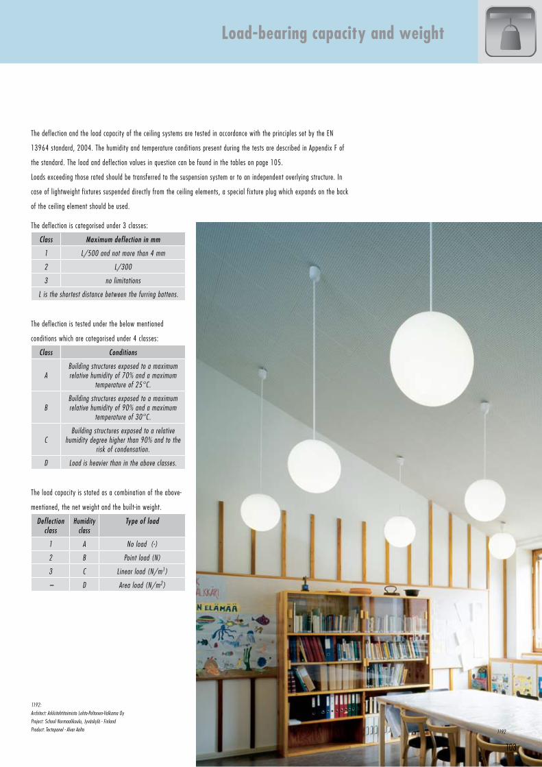
103
1192:
Architect: Arkkitehtitoimisto Lehto-Peltonen-Valkama Oy
Project: School Normaalikoulu, Jyväskylä - Finland
Product: Tectopanel - Alvar Aalto
Load-bearing capacity and weight
The deflection is categorised under 3 classes:
Class Maximum deflection in mm
1 L/500 and not more than 4 mm
2 L/300
3 no limitations
L is the shortest distance between the furring battens.
The deflection is tested under the below mentioned
conditions which are categorised under 4 classes:
Class Conditions
ABuilding structures exposed to a maximum relative humidity of 70% and a maximum
temperature of 25°C.
BBuilding structures exposed to a maximum relative humidity of 90% and a maximum
temperature of 30°C.
CBuilding structures exposed to a relative
humidity degree higher than 90% and to the risk of condensation.
D Load is heavier than in the above classes.
The load capacity is stated as a combination of the above-
mentioned, the net weight and the built-in weight.
Deflection class
Humidity class
Type of load
1 A No load (-)
2 B Point load (N)
3 C Linear load (N/m1)
– D Area load (N/m2)
The deflection and the load capacity of the ceiling systems are tested in accordance with the principles set by the EN
13964 standard, 2004. The humidity and temperature conditions present during the tests are described in Appendix F of
the standard. The load and deflection values in question can be found in the tables on page 105.
Loads exceeding those rated should be transferred to the suspension system or to an independent overlying structure. In
case of lightweight fixtures suspended directly from the ceiling elements, a special fixture plug which expands on the back
of the ceiling element should be used.
1192
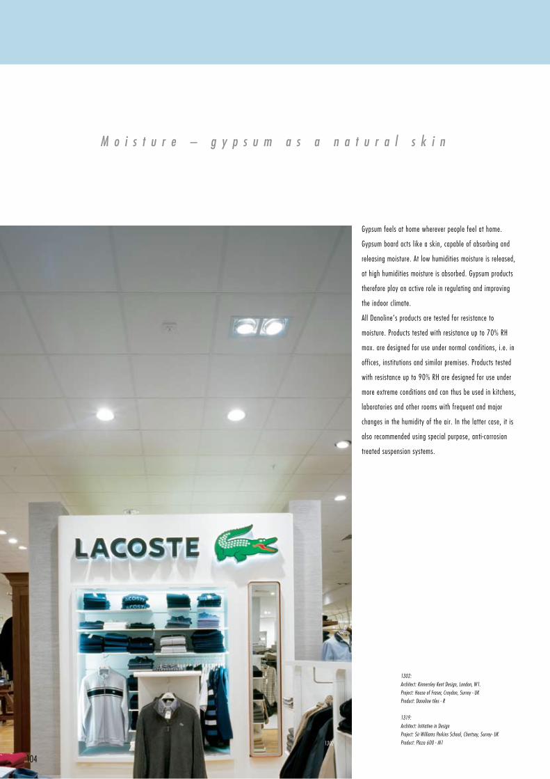
104
M o i s t u r e – g y p s u m a s a n a t u r a l s k i n
Gypsumfeelsathomewhereverpeoplefeelathome.
Gypsumboardactslikeaskin,capableofabsorbingand
releasing moisture. At low humidities moisture is released,
athighhumiditiesmoistureisabsorbed.Gypsumproducts
therefore play an active role in regulating and improving
the indoor climate.
All Danoline’s products are tested for resistance to
moisture.Productstestedwithresistanceupto70%RH
max. are designed for use under normal conditions, i.e. in
offices,institutionsandsimilarpremises.Productstested
with resistance up to 90% RH are designed for use under
more extreme conditions and can thus be used in kitchens,
laboratoriesandotherroomswithfrequentandmajor
changes in the humidity of the air. In the latter case, it is
also recommended using special purpose, anti-corrosion
treated suspension systems.
1302:
Architect: Kinnersley Kent Design, London, W1.
Project: House of Fraser, Croydon, Surrey - UK
Product: Danoline tiles - R
1319:
Architect: Initiative in Design
Project: Sir Williams Perkins School, Chertsey, Surrey- UK
Product: Plaza 600 - M1 1302
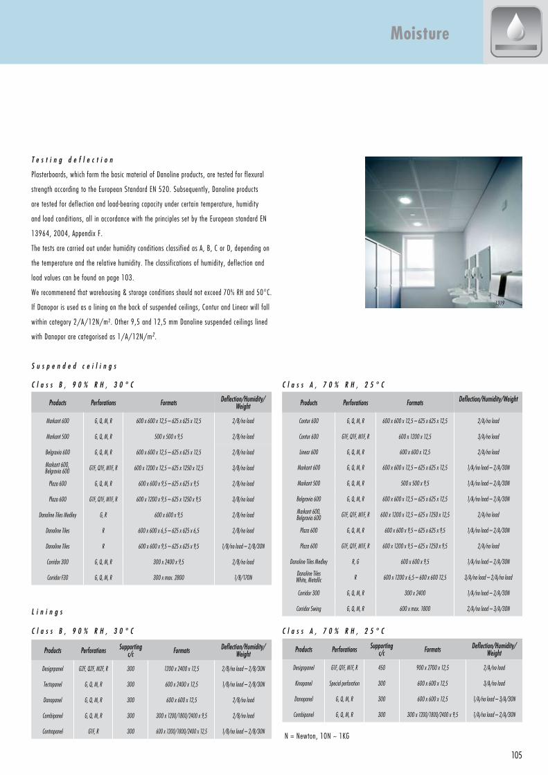
105
T e s t i n g d e f l e c t i o n
Plasterboards,whichformthebasicmaterialofDanolineproducts,aretestedforflexural
strength according to the European Standard EN 520. Subsequently, Danoline products
are tested for deflection and load-bearing capacity under certain temperature, humidity
and load conditions, all in accordance with the principles set by the European standard EN
13964, 2004, Appendix F.
The tests are carried out under humidity conditions classified as A, B, C or D, depending on
the temperature and the relative humidity. The classifications of humidity, deflection and
load values can be found on page 103.
Werecommenendthatwarehousing&storageconditionsshouldnotexceed70%RHand50°C.
If Danopor is used as a lining on the back of suspended ceilings, Contur and Linear will fall
withincategory2/A/12N/m².Other9,5and12,5mmDanolinesuspendedceilingslined
with Danopor are categorised as 1/A/12N/m2.
S u s p e n d e d c e i l i n g s
C l a s s B , 9 0 % R H , 3 0 ° C C l a s s A , 7 0 % R H , 2 5 ° C
L i n i n g s
C l a s s B , 9 0 % R H , 3 0 ° C C l a s s A , 7 0 % R H , 2 5 ° C
Moisture
N=Newton,10N~1KG.
Products Perforations Formats Deflection/Humidity/Weight
Markant 600 G, Q, M, R 600 x 600 x 12,5 – 625 x 625 x 12,5 2/B/no load
Markant 500 G, Q, M, R 500 x 500 x 9,5 2/B/no load
Belgravia 600 G, Q, M, R 600 x 600 x 12,5 – 625 x 625 x 12,5 2/B/no load
Markant 600, Belgravia 600 G1F, Q1F, M1F, R 600 x 1200 x 12,5 – 625 x 1250 x 12,5 3/B/no load
Plaza 600 G, Q, M, R 600 x 600 x 9,5 – 625 x 625 x 9,5 2/B/no load
Plaza 600 G1F, Q1F, M1F, R 600 x 1200 x 9,5 – 625 x 1250 x 9,5 3/B/no load
Danoline Tiles Medley G, R 600 x 600 x 9,5 2/B/no load
Danoline Tiles R 600 x 600 x 6,5 – 625 x 625 x 6,5 2/B/no load
Danoline Tiles R 600 x 600 x 9,5 – 625 x 625 x 9,5 1/B/no load – 2/B/30N
Corridor 300 G, Q, M, R 300 x 2400 x 9,5 2/B/no load
Corridor F30 G, Q, M, R 300 x max. 2800 1/B/170N
Products Perforations Formats Deflection/Humidity/Weight
Contur 600 G, Q, M, R 600 x 600 x 12,5 – 625 x 625 x 12,5 2/A/no load
Contur 600 G1F, Q1F, M1F, R 600 x 1200 x 12,5 3/A/no load
Linear 600 G, Q, M, R 600 x 600 x 12,5 2/A/no load
Markant 600 G, Q, M, R 600 x 600 x 12,5 – 625 x 625 x 12,5 1/A/no load – 2/A/30N
Markant 500 G, Q, M, R 500 x 500 x 9,5 1/A/no load – 2/A/30N
Belgravia 600 G, Q, M, R 600 x 600 x 12,5 – 625 x 625 x 12,5 1/A/no load – 2/A/30N
Markant 600, Belgravia 600 G1F, Q1F, M1F, R 600 x 1200 x 12,5 – 625 x 1250 x 12,5 2/A/no load
Plaza 600 G, Q, M, R 600 x 600 x 9,5 – 625 x 625 x 9,5 1/A/no load – 2/A/30N
Plaza 600 G1F, Q1F, M1F, R 600 x 1200 x 9,5 – 625 x 1250 x 9,5 2/A/no load
Danoline Tiles Medley R, G 600 x 600 x 9,5 1/A/no load – 2/A/30N
Danoline Tiles White, Metallic R 600 x 1200 x 6,5 – 600 x 600 12,5 3/A/no load – 2/A/no load
Corridor 300 G, Q, M, R 300 x 2400 1/A/no load – 2/A/30N
Corridor Swing G, Q, M, R 600 x max. 1800 2/A/no load – 3/A/30N
Products Perforations Supporting c/c Formats Deflection/Humidity/
Weight
Designpanel G2F, Q2F, M2F, R 300 1200 x 2400 x 12,5 2/B/no load – 2/B/30N
Tectopanel G, Q, M, R 300 600 x 2400 x 12,5 1/B/no load – 2/B/30N
Danopanel G, Q, M, R 300 600 x 600 x 12,5 2/B/no load
Combipanel G, Q, M, R 300 300 x 1200/1800/2400 x 9,5 2/B/no load
Contrapanel G1F, R 300 600 x 1200/1800/2400 x 12,5 1/B/no load – 2/B/30N
Products Perforations Supporting c/c Formats Deflection/Humidity/
Weight
Designpanel G1F, Q1F, M1F, R 450 900 x 2700 x 12,5 2/A/no load
Kinopanel Special perforation 300 600 x 600 x 12,5 3/A/no load
Danopanel G, Q, M, R 300 600 x 600 x 12,5 1/A/no load – 3/A/30N
Combipanel G, Q, M, R 300 300 x 1200/1800/2400 x 9,5 1/A/no load – 2/A/30N
N=Newton,10N~1KG
1319
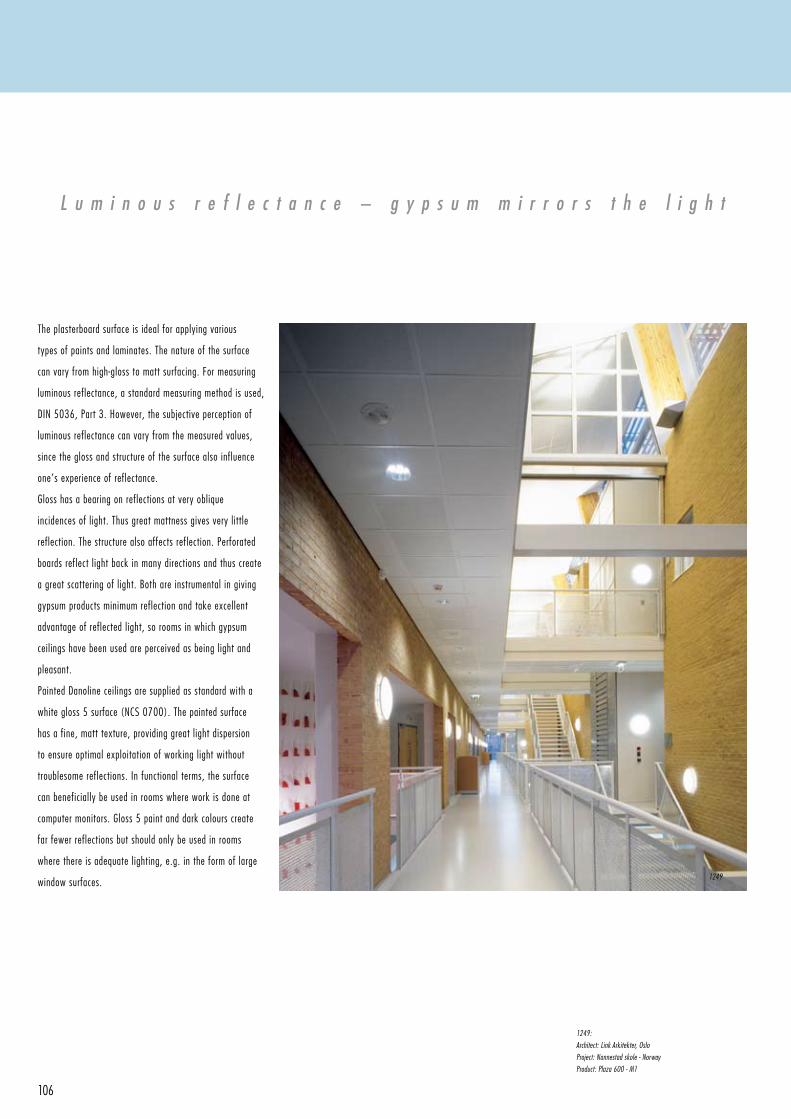
106
L u m i n o u s r e f l e c t a n c e – g y p s u m m i r r o r s t h e l i g h t
The plasterboard surface is ideal for applying various
types of paints and laminates. The nature of the surface
can vary from high-gloss to matt surfacing. For measuring
luminous reflectance, a standard measuring method is used,
DIN5036,Part3.However,thesubjectiveperceptionof
luminous reflectance can vary from the measured values,
since the gloss and structure of the surface also influence
one’s experience of reflectance.
Glosshasabearingonreflectionsatveryoblique
incidences of light. Thus great mattness gives very little
reflection.Thestructurealsoaffectsreflection.Perforated
boards reflect light back in many directions and thus create
a great scattering of light. Both are instrumental in giving
gypsum products minimum reflection and take excellent
advantage of reflected light, so rooms in which gypsum
ceilings have been used are perceived as being light and
pleasant.
PaintedDanolineceilingsaresuppliedasstandardwitha
white gloss 5 surface (NCS 0700). The painted surface
has a fine, matt texture, providing great light dispersion
to ensure optimal exploitation of working light without
troublesome reflections. In functional terms, the surface
can beneficially be used in rooms where work is done at
computermonitors.Gloss5paintanddarkcolourscreate
far fewer reflections but should only be used in rooms
where there is adequate lighting, e.g. in the form of large
window surfaces.
1249:
Architect: Link Arkitekter, Oslo
Project: Nannestad skole - Norway
Product: Plaza 600 - M1
1249
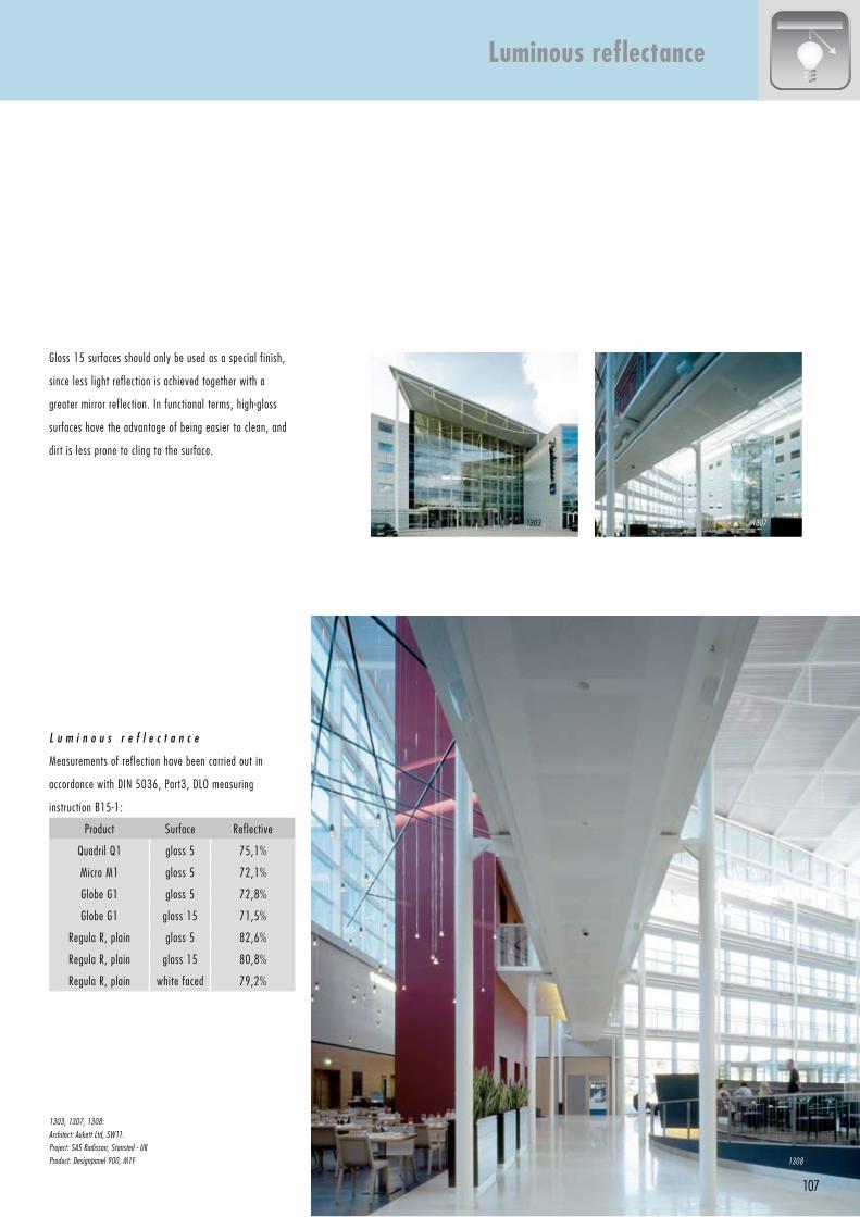
107
L u m i n o u s r e f l e c t a n c e
Measurements of reflection have been carried out in
accordancewithDIN5036,Part3,DLOmeasuring
instruction B15-1:
Product Surface Reflective
QuadrilQ1 gloss 5 75,1%
Micro M1 gloss 5 72,1%
GlobeG1 gloss 5 72,8%
GlobeG1 gloss 15 71,5%
Regula R, plain gloss 5 82,6%
Regula R, plain gloss 15 80,8%
Regula R, plain white faced 79,2%
Gloss15surfacesshouldonlybeusedasaspecialfinish,
since less light reflection is achieved together with a
greater mirror reflection. In functional terms, high-gloss
surfaces have the advantage of being easier to clean, and
dirt is less prone to cling to the surface.
Luminous reflectance
1303, 1307, 1308:
Architect: Aukett Ltd, SW11.
Project: SAS Radisson, Stansted - UK
Product: Designpanel 900, M1F
1303 1307
1308
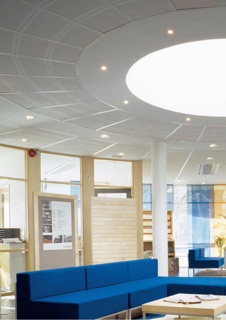
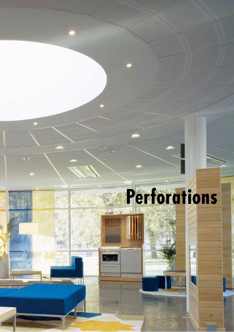
Perforations
1178
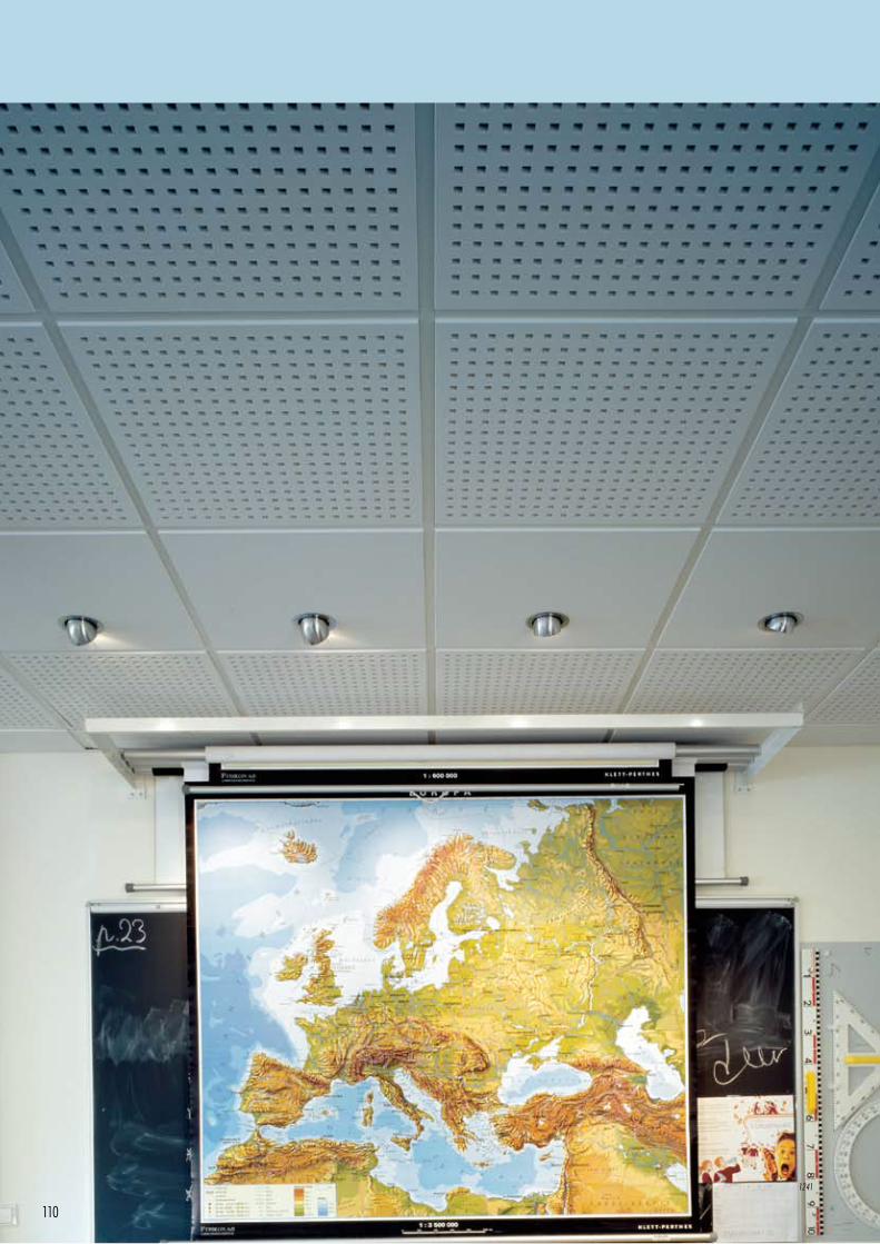
110
1241
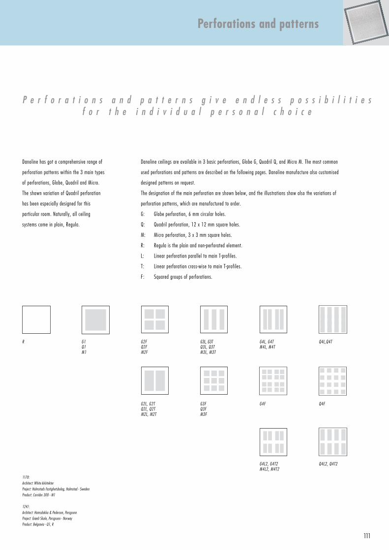
111
Danoline has got a comprehensive range of
perforation patterns within the 3 main types
of perforations, Globe, Quadril and Micro.
The shown variation of Quadril perforation
has been especially designed for this
particular room. Naturally, all ceiling
systems come in plain, Regula.
P e r f o r a t i o n s a n d p a t t e r n s g i v e e n d l e s s p o s s i b i l i t i e sf o r t h e i n d i v i d u a l p e r s o n a l c h o i c e
Danoline ceilings are available in 3 basic perforations, Globe G, Quadril Q, and Micro M. The most common
used perforations and patterns are described on the following pages. Danoline manufacture also customised
designed patterns on request.
The designation of the main perforation are shown below, and the illustrations show also the variations of
perforation patterns, which are manufactured to order.
G: Globe perforation, 6 mm circular holes.
Q: Quadril perforation, 12 x 12 mm square holes.
M: Micro perforation, 3 x 3 mm square holes.
R: Regula is the plain and non-perforated element.
L: Linear perforation parallel to main T-profiles.
T: Linear perforation cross-wise to main T-profiles.
F: Squared groups of perforations.
1178:
Architect: White Arkitekter
Project: Halmstads Fastighetsbolag, Halmstad - Sweden
Product: Corridor 300 - M1
1241:
Architect: Hamsdokka & Pedersen, Porsgrunn
Project: Grønli Skole, Porsgrunn - Norway
Product: Belgravia - Q1, R
Perforations and patterns
G1 Q1M1
G2FQ2FM2F
G3L, G3TQ3L, Q3TM3L, M3T
G4L, G4TM4L, M4T
R
G2L, G2TQ2L, Q2TM2L, M2T
G3FQ3FM3F
G4F
G4L2, G4T2M4L2, M4T2
Q4L,Q4T
Q4F
Q4L2, Q4T2
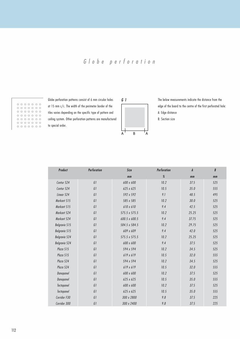
A B A
G 1
112
G l o b e p e r f o r a t i o n
Globe perforation patterns consist of 6 mm circular holes
at 15 mm c/c. The width of the perimeter border of the
tiles varies depending on the specific type of pattern and
ceiling system. Other perforation patterns are manufactured
to special order.
Product Perforation Size
mm
Perforation
%
A
mm
B
mm
Contur S24 G1 600 x 600 10.2 37.5 525
Contur S24 G1 625 x 625 10.5 35.0 555
Linear S24 G1 592 x 592 9.1 48.5 495
Markant S15 G1 585 x 585 10.2 30.0 525
Markant S15 G1 610 x 610 9.4 42.5 525
Markant S24 G1 575.5 x 575.5 10.2 25.25 525
Markant S24 G1 600.5 x 600.5 9.4 37.75 525
Belgravia S15 G1 584.5 x 584.5 10.2 29.75 525
Belgravia S15 G1 609 x 609 9.4 42.0 525
Belgravia S24 G1 575.5 x 575.5 10.2 25.25 525
Belgravia S24 G1 600 x 600 9.4 37.5 525
Plaza S15 G1 594 x 594 10.2 34.5 525
Plaza S15 G1 619 x 619 10.5 32.0 555
Plaza S24 G1 594 x 594 10.2 34.5 525
Plaza S24 G1 619 x 619 10.5 32.0 555
Danopanel G1 600 x 600 10.2 37.5 525
Danopanel G1 625 x 625 10.5 35.0 555
Tectopanel G1 600 x 600 10.2 37.5 525
Tectopanel G1 625 x 625 10.5 35.0 555
Corridor F30 G1 300 x 2800 9.8 37.5 225
Corridor 300 G1 300 x 2400 9.8 37.5 225
The below measurements indicate the distance from the
edge of the board to the centre of the first perforated hole:
A: Edge distance
B: Section size
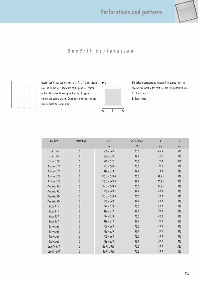
A B A
Q 1
113
Quadril perforation patterns consist of 12 x 12 mm square
holes at 30 mm c/c. The width of the perimeter border
of the tiles varies depending on the specific type of
pattern and ceiling system. Other perforation patterns are
manufactured to special order.
Product Perforation Size
mm
Perforation
%
A
mm
B
mm
Contur S24 Q1 600 x 600 13.0 45.0 510
Contur S24 Q1 625 x 625 11.9 57.5 510
Linear S24 Q1 592 x 592 10.2 71.0 450
Markant S15 Q1 585 x 585 13.0 37.5 510
Markant S15 Q1 610 x 610 11.9 50.0 510
Markant S24 Q1 575.5 x 575.5 13.0 32.75 510
Markant S24 Q1 600.5 x 600.5 11.9 45.25 510
Belgravia S15 Q1 584.5 x 584.5 13.0 36.75 510
Belgravia S15 Q1 609 x 609 11.9 49.0 510
Belgravia S24 Q1 575.5 x 575.5 13.0 32.0 510
Belgravia S24 Q1 600 x 600 11.9 45.0 510
Plaza S15 Q1 594 x 594 13.0 42.0 510
Plaza S15 Q1 619 x 619 11.9 47.0 510
Plaza S24 Q1 594 x 594 13.0 42.0 510
Plaza S24 Q1 619 x 619 11.9 47.0 510
Danopanel Q1 600 x 600 13.0 45.0 510
Danopanel Q1 625 x 625 11.9 57.5 510
Tectopanel Q1 600 x 600 13.0 45.0 510
Tectopanel Q1 625 x 625 11.9 57.5 510
Corridor F30 Q1 300 x 2800 12.3 45.0 225
Corridor 300 Q1 300 x 2400 12.3 45.0 225
Perforations and patterns
The below measurements indicate the distance from the
edge of the board to the centre of the first perforated hole:
A: Edge distance
B: Section size
Q u a d r i l p e r f o r a t i o n

A B A
M 1
114
M i c r o p e r f o r a t i o n
Product Perforation Size
mm
Perforation
%
A
mm
B
mm
Contur S24 M1 600 x 600 10.2 37.5 525
Contur S24 M1 625 x 625 10.7 33.33 558.33
Linear S24 M1 592 x 592 10.2 33.5 525
Markant S15 M1 585 x 585 10.2 30.0 525
Markant S15 M1 610 x 610 10.7 42.5 525
Markant S24 M1 575.5 x 575.5 10.2 25.25 525
Markant S24 M1 600.5 x 600.5 10.7 37.75 525
Belgravia S15 M1 584.5 x 584.5 10.2 29.75 525
Belgravia S15 M1 609 x 609 10.7 42.0 525
Belgravia S24 M1 575.5 x 575.5 10.2 25.25 525
Belgravia S24 M1 600 x 600 10.7 37.5 525
Plaza S15 M1 594 x 594 10.2 34.5 525
Plaza S15 M1 619 x 619 10.7 30.33 558.33
Plaza S24 M1 594 x 594 10.2 34.5 525
Plaza S24 M1 619 x 619 10.7 30.33 558.33
Danopanel M1 600 x 600 10.2 37.5 525
Danopanel M1 625 x 625 10.7 35.0 555
Tectopanel M1 600 x 600 10.2 37.5 525
Tectopanel M1 625 x 625 10.7 35.0 555
Corridor F30 M1 300 x 2800 9.8 37.5 225
Corridor 300 M1 300 x 2400 9.8 37.5 225
Micro perforation patterns consist of 3 x 3 mm square holes
at 8.33 mm c/c. The width of the perimeter border of the
tiles varies depending on the specific type of pattern and
ceiling system. Other perforation patterns are manufactured
to special order.
The below measurements indicate the distance from the
edge of the board to the centre of the first perforated hole:
A: Edge distance
B: Section size
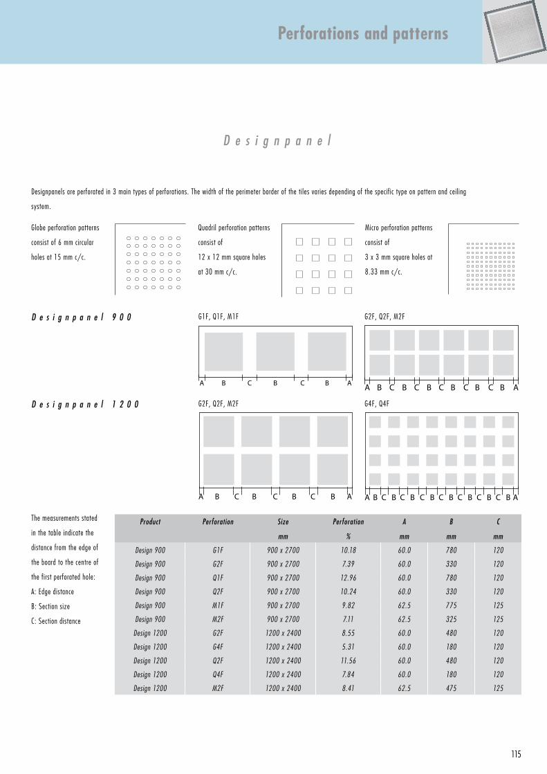
G1F, Q1F, M1F
A B C B C B A
G2F, Q2F, M2F
A B C CB CB C C AB B B
G4F, Q4F
A AB C B C B C B C B C B C B C BA ABBCB BC C
G2F, Q2F, M2F
115
D e s i g n p a n e l
Globe perforation patterns
consist of 6 mm circular
holes at 15 mm c/c.
Quadril perforation patterns
consist of
12 x 12 mm square holes
at 30 mm c/c.
Micro perforation patterns
consist of
3 x 3 mm square holes at
8.33 mm c/c.
D e s i g n p a n e l 9 0 0
D e s i g n p a n e l 1 2 0 0
The measurements stated
in the table indicate the
distance from the edge of
the board to the centre of
the first perforated hole:
A: Edge distance
B: Section size
C: Section distance
Designpanels are perforated in 3 main types of perforations. The width of the perimeter border of the tiles varies depending of the specific type on pattern and ceiling
system.
Perforations and patterns
Product Perforation Size
mm
Perforation
%
A
mm
B
mm
C
mm
Design 900 G1F 900 x 2700 10.18 60.0 780 120
Design 900 G2F 900 x 2700 7.39 60.0 330 120
Design 900 Q1F 900 x 2700 12.96 60.0 780 120
Design 900 Q2F 900 x 2700 10.24 60.0 330 120
Design 900 M1F 900 x 2700 9.82 62.5 775 125
Design 900 M2F 900 x 2700 7.11 62.5 325 125
Design 1200 G2F 1200 x 2400 8.55 60.0 480 120
Design 1200 G4F 1200 x 2400 5.31 60.0 180 120
Design 1200 Q2F 1200 x 2400 11.56 60.0 480 120
Design 1200 Q4F 1200 x 2400 7.84 60.0 180 120
Design 1200 M2F 1200 x 2400 8.41 62.5 475 125
Cleaning and maintenance
1059
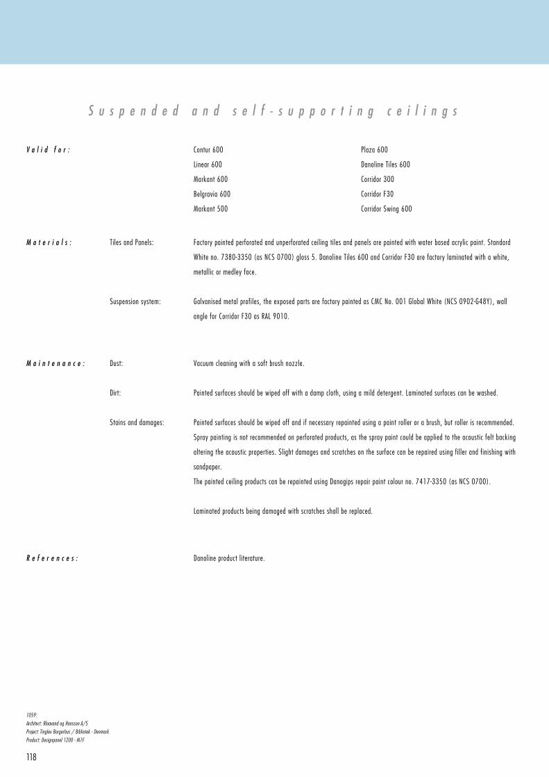
118
S u s p e n d e d a n d s e l f - s u p p o r t i n g c e i l i n g s
V a l i d f o r : Contur 600
Linear 600
Markant 600
Belgravia 600
Markant 500
Plaza 600
Danoline Tiles 600
Corridor 300
Corridor F30
Corridor Swing 600
M a t e r i a l s : Tiles and Panels:
Suspension system:
Factory painted perforated and unperforated ceiling tiles and panels are painted with water based acrylic paint. Standard
White no. 7380-3350 (as NCS 0700) gloss 5. Danoline Tiles 600 and Corridor F30 are factory laminated with a white,
metallic or medley face.
Galvanised metal profiles, the exposed parts are factory painted as CMC No. 001 Global White (NCS 0902-G48Y), wall
angle for Corridor F30 as RAL 9010.
M a i n t e n a n c e : Dust:
Dirt:
Stains and damages:
Vacuum cleaning with a soft brush nozzle.
Painted surfaces should be wiped off with a damp cloth, using a mild detergent. Laminated surfaces can be washed.
Painted surfaces should be wiped off and if necessary repainted using a paint roller or a brush, but roller is recommended.
Spray painting is not recommended on perforated products, as the spray paint could be applied to the acoustic felt backing
altering the acoustic properties. Slight damages and scratches on the surface can be repaired using fil ler and finishing with
sandpaper.
The painted ceiling products can be repainted using Danogips repair paint colour no. 7417-3350 (as NCS 0700).
Laminated products being damaged with scratches shall be replaced.
R e f e r e n c e s : Danoline product literature.
1059:
Architect: Blaavand og Hansson A/S
Project: Tinglev Borgerhus / Bibliotek - Denmark
Product: Designpanel 1200 - M1F
119
C e i l i n g l i n i n g s , a c o u s t i c a n d p l a i n
V a l i d f o r :
Factory painted perforated and unperforated panels are painted with water based acrylic paint. Standard White no. 7380-
3350 ( as NCS 0700) gloss 5. Contrapanel is factory laminated with a white face.
M a i n t e n a n c e :
R e f e r e n c e s : Danoline product literature.
Dust:
Dirt:
Stains and damages:
Vacuum cleaning with a soft brush nozzle.
Painted surfaces should be wiped off with a damp cloth, using a mild detergent.
Painted surfaces should be wiped off and if necessary repainted using a paint roller or a brush, but roller is recommended.
Spray painting is not recommended on perforated products, as the spray paint could be applied to the acoustic felt backing
altering the acoustic properties.
Slight damages and scratches on the surface can be repaired using fil ler and finishing with sandpaper.
The painted ceiling products can be repainted using Danogips repair paint colour no. 7417-3350 (as NCS 0700).
M a t e r i a l s : Panels:
Danopanel
Combipanel
Designpanels 900 and 1200
Tectopanel
Contrapanel
Kinopanel
Curvex (arches)
Mitex (folded panels)
Cleaning and maintenance
Summary
1255
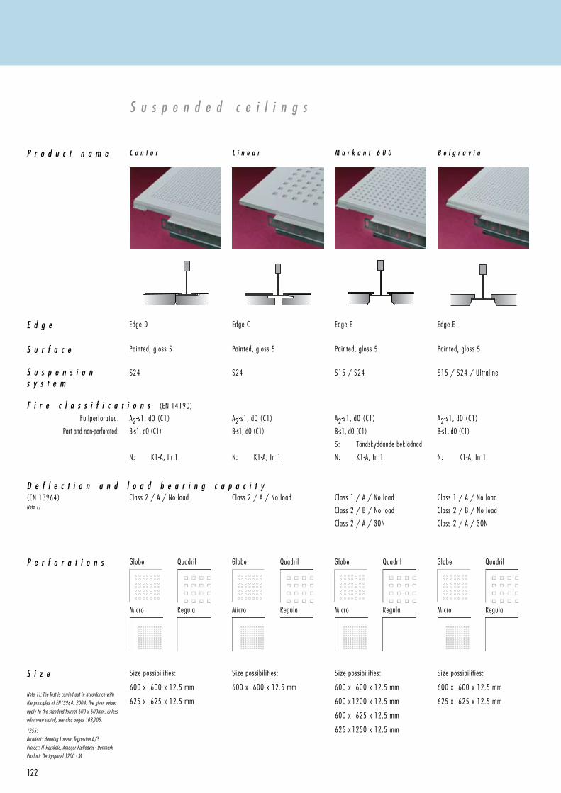
122
P r o d u c t n a m e
E d g e Edge E Edge EEdge D Edge C
F i r e c l a s s i f i c a t i o n s (EN 14190)
S u s p e n d e d c e i l i n g s
P e r f o r a t i o n s
Size possibilities:
600 x 600 x 12.5 mm
625 x 625 x 12.5 mm
Size possibilities:
600 x 600 x 12.5 mm
Size possibilities:
600 x 600 x 12.5 mm
600 x 1200 x 12.5 mm
600 x 625 x 12.5 mm
625 x 1250 x 12.5 mm
Size possibilities:
600 x 600 x 12.5 mm
625 x 625 x 12.5 mm
S i z e
S u r f a c e Painted, gloss 5 Painted, gloss 5Painted, gloss 5 Painted, gloss 5
S u s p e n s i o ns y s t e m
S15 / S24 S15 / S24 / UltralineS24 S24
1255:
Architect: Henning Larsens Tegnestue A/S
Project: IT Højskole, Amager Fælledvej - Denmark
Product: Designpanel 1200 - M
D e f l e c t i o n a n d l o a d b e a r i n g c a p a c i t y (EN 13964)Note 1)
A2-s1, d0 (C1)
B-s1, d0 (C1)
N: K1-A, In 1
A2-s1, d0 (C1)
B-s1, d0 (C1)
S: Tändskyddande beklädnad
N: K1-A, In 1
A2-s1, d0 (C1)
B-s1, d0 (C1)
N: K1-A, In 1
A2-s1, d0 (C1)
B-s1, d0 (C1)
N: K1-A, In 1
Class 2 / A / No load Class 2 / A / No load Class 1 / A / No load
Class 2 / B / No load
Class 2 / A / 30N
Class 1 / A / No load
Class 2 / B / No load
Class 2 / A / 30N
Note 1): The Test is carried out in accordance with
the principles of EN13964: 2004. The given values
apply to the standard format 600 x 600mm, unless
otherwise stated, see also pages 103,105.
C o n t u r L i n e a r M a r k a n t 6 0 0 B e l g r a v i a
Fullperforated:
Part and non-perforated:
Micro Regula
Globe Quadril
Micro Regula
Globe Quadril
Micro Regula
Globe Quadril
Micro Regula
Globe Quadril
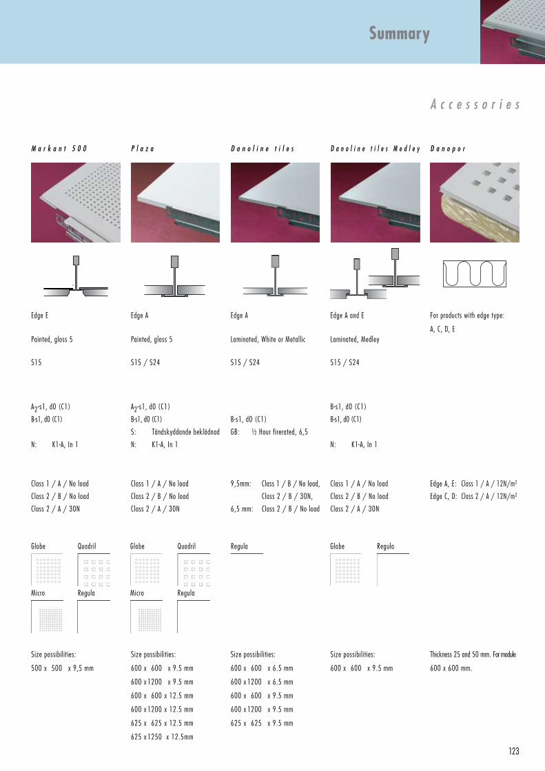
123
A c c e s s o r i e s
Edge AEdge E Edge A For products with edge type:
A, C, D, E
Size possibilities:
600 x 600 x 9.5 mm
600 x 1200 x 9.5 mm
600 x 600 x 12.5 mm
600 x 1200 x 12.5 mm
625 x 625 x 12.5 mm
625 x 1250 x 12.5mm
Size possibilities:
500 x 500 x 9,5 mm
Size possibilities:
600 x 600 x 6.5 mm
600 x 1200 x 6.5 mm
600 x 600 x 9.5 mm
600 x 1200 x 9.5 mm
625 x 625 x 9.5 mm
Thickness 25 and 50 mm. For module
600 x 600 mm.
Size possibilities:
600 x 600 x 9.5 mm
Painted, gloss 5Painted, gloss 5 Laminated, White or Metallic Laminated, Medley
Edge A and E
S15 / S24S15 S15 / S24 S15 / S24
Summary
B-s1, d0 (C1)
GB: ½ Hour firerated, 6,5
A2-s1, d0 (C1)
B-s1, d0 (C1)
N: K1-A, In 1
A2-s1, d0 (C1)
B-s1, d0 (C1)
S: Tändskyddande beklädnad
N: K1-A, In 1
B-s1, d0 (C1)
B-s1, d0 (C1)
N: K1-A, In 1
Class 1 / A / No load
Class 2 / B / No load
Class 2 / A / 30N
Class 1 / A / No load
Class 2 / B / No load
Class 2 / A / 30N
9,5mm: Class 1 / B / No load,
Class 2 / B / 30N,
6,5 mm: Class 2 / B / No load
Class 1 / A / No load
Class 2 / B / No load
Class 2 / A / 30N
Edge A, E: Class 1 / A / 12N/m²
Edge C, D: Class 2 / A / 12N/m²
P l a z aM a r k a n t 5 0 0 D a n o l i n e t i l e s D a n o p o rD a n o l i n e t i l e s M e d l e y
Regula
Micro Regula
Globe Quadril
Micro Regula
Globe Quadril Globe Regula
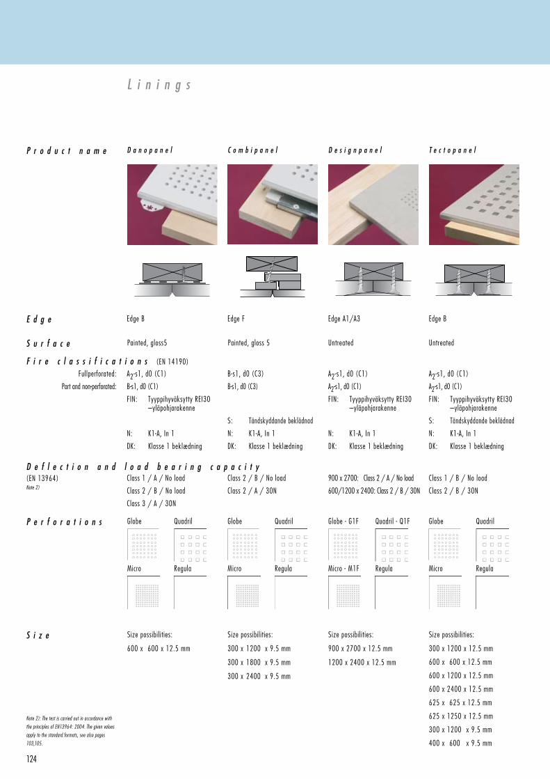
124
Size possibilities:
600 x 600 x 12.5 mm
Size possibilities:
300 x 1200 x 9.5 mm
300 x 1800 x 9.5 mm
300 x 2400 x 9.5 mm
Size possibilities:
900 x 2700 x 12.5 mm
1200 x 2400 x 12.5 mm
Size possibilities:
300 x 1200 x 12.5 mm
600 x 600 x 12.5 mm
600 x 1200 x 12.5 mm
600 x 2400 x 12.5 mm
625 x 625 x 12.5 mm
625 x 1250 x 12.5 mm
300 x 1200 x 9.5 mm
400 x 600 x 9.5 mm
Edge A1/A3 Edge BEdge B Edge F
L i n i n g s
Painted, gloss5 Painted, gloss 5 Untreated Untreated
P r o d u c t n a m e
E d g e
F i r e c l a s s i f i c a t i o n s (EN 14190)
S i z e
P e r f o r a t i o n s
S u r f a c e
D e f l e c t i o n a n d l o a d b e a r i n g c a p a c i t y (EN 13964)Note 2)
B-s1, d0 (C3)
B-s1, d0 (C3)
S: Tändskyddande beklädnad
N: K1-A, In 1
DK: Klasse 1 beklædning
A2-s1, d0 (C1)
B-s1, d0 (C1)
FIN: Tyyppihyväksytty REI30 –yläpohjarakenne
N: K1-A, In 1
DK: Klasse 1 beklædning
A2-s1, d0 (C1)
A2-s1, d0 (C1)
FIN: Tyyppihyväksytty REI30 –yläpohjarakenne
N: K1-A, In 1
DK: Klasse 1 beklædning
A2-s1, d0 (C1)
A2-s1, d0 (C1)
FIN: Tyyppihyväksytty REI30 –yläpohjarakenne
S: Tändskyddande beklädnad
N: K1-A, In 1
DK: Klasse 1 beklædning
Class 1 / A / No load
Class 2 / B / No load
Class 3 / A / 30N
Class 2 / B / No load
Class 2 / A / 30N
900 x 2700: Class 2 / A / No load
600/1200 x 2400: Class 2 / B / 30N
Class 1 / B / No load
Class 2 / B / 30N
Note 2): The test is carried out in accordance with
the principles of EN13964: 2004. The given values
apply to the standard formats, see also pages
103,105.
D a n o p a n e l C o m b i p a n e l D e s i g n p a n e l T e c t o p a n e l
Fullperforated:
Part and non-perforated:
Globe Quadril Globe Quadril Globe - G1F Quadril - Q1F Globe Quadril
Micro Regula Micro Regula Micro - M1F Regula Micro Regula
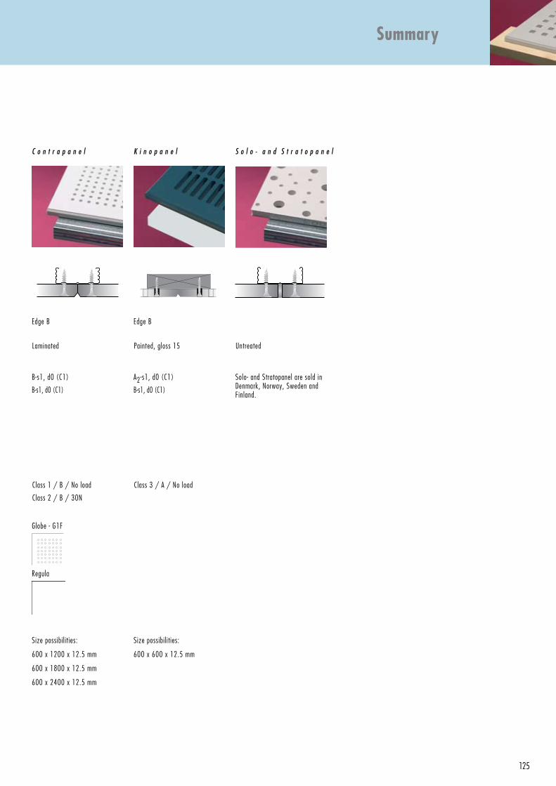
125
Size possibilities:
600 x 600 x 12.5 mm
Size possibilities:
600 x 1200 x 12.5 mm
600 x 1800 x 12.5 mm
600 x 2400 x 12.5 mm
Edge BEdge B
L i n i n g s
S o l o - a n d S t r a t o p a n e l
Laminated Painted, gloss 15 Untreated
Summary
Solo- and Stratopanel are sold in Denmark, Norway, Sweden and Finland.
B-s1, d0 (C1)
B-s1, d0 (C1)
A2-s1, d0 (C1)
B-s1, d0 (C1)
Class 1 / B / No load
Class 2 / B / 30N
Class 3 / A / No load
K i n o p a n e lC o n t r a p a n e l
Globe - G1F
Regula
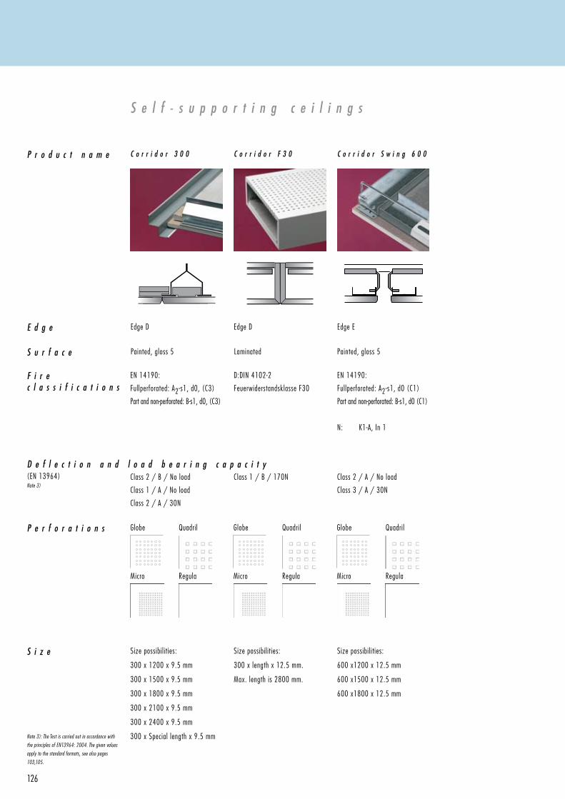
126
Size possibilities:
300 x 1200 x 9.5 mm
300 x 1500 x 9.5 mm
300 x 1800 x 9.5 mm
300 x 2100 x 9.5 mm
300 x 2400 x 9.5 mm
300 x Special length x 9.5 mm
Size possibilities:
300 x length x 12.5 mm.
Max. length is 2800 mm.
Size possibilities:
600 x 1200 x 12.5 mm
600 x 1500 x 12.5 mm
600 x 1800 x 12.5 mm
Edge EEdge D Edge D
S e l f - s u p p o r t i n g c e i l i n g s
Painted, gloss 5 Laminated Painted, gloss 5
P r o d u c t n a m e
E d g e
S i z e
S u r f a c e
F i r ec l a s s i f i c a t i o n s
P e r f o r a t i o n s
D e f l e c t i o n a n d l o a d b e a r i n g c a p a c i t y(EN 13964)Note 3)
Note 3): The Test is carried out in accordance with
the principles of EN13964: 2004. The given values
apply to the standard formats, see also pages
103,105.
EN 14190:
Fullperforated: A2-s1, d0, (C3)
Part and non-perforated: B-s1, d0, (C3)
D:DIN 4102-2
Feuerwiderstandsklasse F30
EN 14190:
Fullperforated: A2-s1, d0 (C1)
Part and non-perforated: B-s1, d0 (C1)
N: K1-A, In 1
Class 2 / B / No load
Class 1 / A / No load
Class 2 / A / 30N
Class 1 / B / 170N Class 2 / A / No load
Class 3 / A / 30N
C o r r i d o r 3 0 0 C o r r i d o r F 3 0 C o r r i d o r S w i n g 6 0 0
Globe Quadril Globe Quadril Globe Quadril
Micro Regula Micro Regula Micro Regula
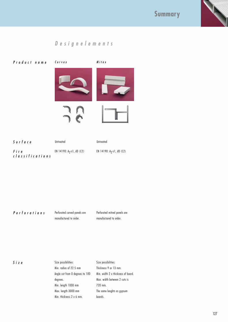
127
D e s i g n e l e m e n t s
Perforated curved panels are
manufactured to order.
Perforated mitred panels are
manufactured to order.
Size possibilities:
Min. radius of 22.5 mm
Angle cut from 0 degrees to 180
degrees.
Min. length 1000 mm
Max. length 3000 mm
Min. thickness 2 x 6 mm.
Size possibilities:
Thickness 9 or 13 mm.
Min. width 2 x thickness of board.
Max. width between 2 cuts is
720 mm.
The same lenghts as gypsum
boards.
Untreated Untreated
Summary
P r o d u c t n a m e
S i z e
S u r f a c e
P e r f o r a t i o n s
F i r ec l a s s i f i c a t i o n s
EN 14190: A2-s1, d0 (C2) EN 14190: A2-s1, d0 (C2)
C u r v e x M i t e x
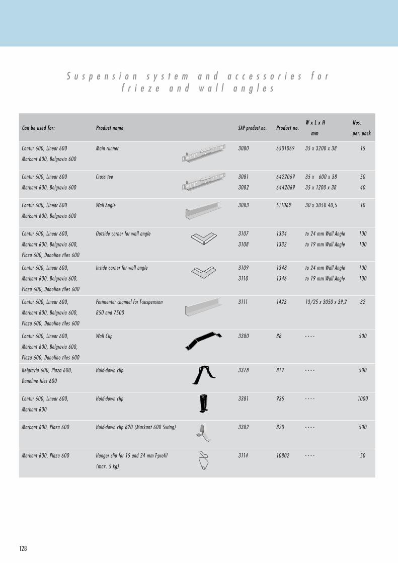
128
S u s p e n s i o n s y s t e m a n d a c c e s s o r i e s f o rf r i e z e a n d w a l l a n g l e s
Can be used for: Product name SAP product no. Product no.W x L x H
mm
Nos.
per. pack
Contur 600, Linear 600
Markant 600, Belgravia 600
Main runner 3080 6501069 35 x 3200 x 38 15
Contur 600, Linear 600
Markant 600, Belgravia 600
Cross tee 3081
3082
6422069
6442069
35 x 600 x 38
35 x 1200 x 38
50
40
Contur 600, Linear 600
Markant 600, Belgravia 600
Wall Angle 3083 511069 30 x 3050 40,5 10
Contur 600, Linear 600,
Markant 600, Belgravia 600,
Plaza 600, Danoline tiles 600
Outside corner for wall angle 3107
3108
1334
1332
to 24 mm Wall Angle
to 19 mm Wall Angle
100
100
Contur 600, Linear 600,
Markant 600, Belgravia 600,
Plaza 600, Danoline tiles 600
Inside corner for wall angle 3109
3110
1348
1346
to 24 mm Wall Angle
to 19 mm Wall Angle
100
100
Contur 600, Linear 600,
Markant 600, Belgravia 600,
Plaza 600, Danoline tiles 600
Perimenter channel for T-suspension
850 and 7500
3111 1423 13/25 x 3050 x 39,2 32
Contur 600, Linear 600,
Markant 600, Belgravia 600,
Plaza 600, Danoline tiles 600
Wall Clip 3380 88 - - - - 500
Belgravia 600, Plaza 600,
Danoline tiles 600
Hold-down clip 3378 819 - - - - 500
Contur 600, Linear 600,
Markant 600
Hold-down clip 3381 935 - - - - 1000
Markant 600, Plaza 600 Hold-down clip 820 (Markant 600 Swing) 3382 820 - - - - 500
Markant 600, Plaza 600 Hanger clip for 15 and 24 mm T-profil
(max. 5 kg)
3114 10802 - - - - 50
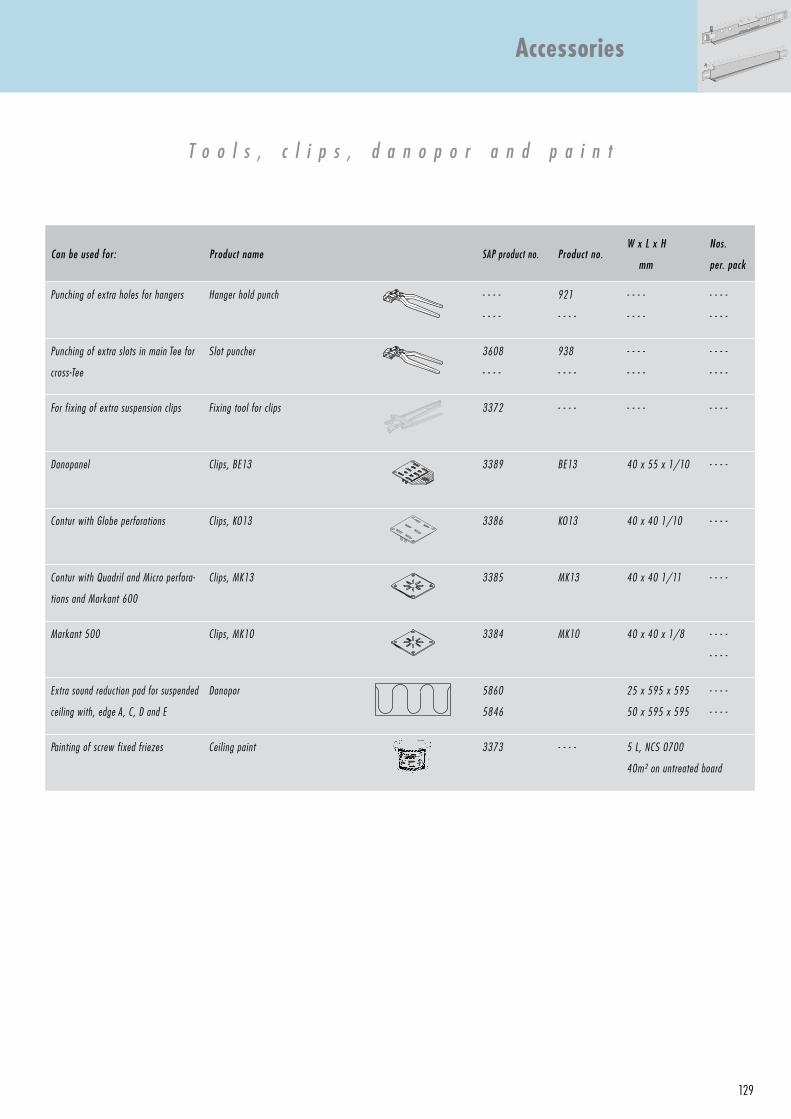
129
Can be used for: Product name SAP product no. Product no.W x L x H
mm
Nos.
per. pack
Punching of extra holes for hangers Hanger hold punch - - - -
- - - -
921
- - - -
- - - -
- - - -
- - - -
- - - -
Punching of extra slots in main Tee for
cross-Tee
Slot puncher 3608
- - - -
938
- - - -
- - - -
- - - -
- - - -
- - - -
For fixing of extra suspension clips Fixing tool for clips 3372 - - - - - - - - - - - -
Danopanel Clips, BE13 3389 BE13 40 x 55 x 1/10 - - - -
Contur with Globe perforations Clips, KO13 3386 KO13 40 x 40 1/10 - - - -
Contur with Quadril and Micro perfora-
tions and Markant 600
Clips, MK13 3385 MK13 40 x 40 1/11 - - - -
Markant 500 Clips, MK10 3384 MK10 40 x 40 x 1/8 - - - -
- - - -
Extra sound reduction pad for suspended
ceiling with, edge A, C, D and E
Danopor 5860
5846
25 x 595 x 595
50 x 595 x 595
- - - -
- - - -
Painting of screw fixed friezes Ceiling paint 3373 - - - - 5 L, NCS 0700
40m² on untreated board
T o o l s , c l i p s , d a n o p o r a n d p a i n t
Accessories
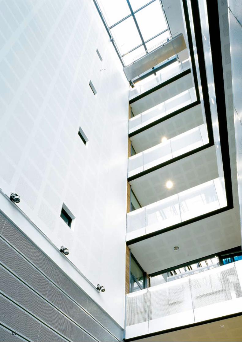
130
1148
D a n o l i n e U K
Unit 3, Silverdale Road Hayes, Middlesex UB3 3Bl Phone: 020 8561 2389 Fax: 020 8561 3483 www.danoline.come-Mail: [email protected]
D a n o l i n e A / S , H e a d o f f i c e
Antoinettevej 3 DK - 2500 Valby Phone: (+45) 3615 9000 Fax: (+45) 3615 9001 www.danoline.dk e-Mail: [email protected]
D a n o l i n e A / S , S a l e s a n d T e c h n i c a l s u p p o r t
Kløvermarksvej 6 DK - 9500 Hobro Phone: (+45) 9657 3000 Fax: (+45) 9657 3001 www.danoline.dk e-Mail: [email protected]
A u s t r i a K n a u f G e s . m . b . H .
Phone: (+43) 1-58068-0 Fax: (+43) 1-58068-483 www.knauf.at e-Mail: [email protected]
B e l g i u m K n a u f G i p s
Phone: (+32) 4-2738-311 Fax: (+32) 4-2738-330 www.knauf.be e-Mail: [email protected]
B u l g a r i a K n a u f E O O D
Phone: (+359) 2-9178941 Fax: (+359) 2-9178943 www.knauf.bg e-Mail: [email protected]
E s t o n i a K n a u f & P a r t n e r U Ü
Phone: (+372) 6518 690 Fax: (+372) 6518 691 www.knauf.ee e-Mail: [email protected]
F r a n c e K n a u f S N C
Phone: (+33) 389-72-1100 Fax: (+33) 389-72-1203 www.knauf.fr e-Mail: [email protected]
K n a u f G r o u p P a r t n e r s
D a n o l i n e o f f i c e s
March 2007CI/Sfb: (35)99.03.07
1148:
Architect: Liljewall Arkitekter Göteborg
Project: Biotechhuset, Göteborg - Sweden
Product: Designpanel 900 - M2F
D a n o l i n e W e s t E u r o p e
France, Belgium, Switzerland, Spain and ItalyTel.: +33 (0)6 25 26 50 00www.danoline.come-Mail:[email protected]
D a n o g i p s M i d d l e E a s t
P.O. Box 53255 Jebel Ali Free Zone Dubai United Arab Emirates Phone: (+971) 4 8812281 Fax: (+971) 4 8812151 www.danoline.come Mail: [email protected]
D a n o g i p s G m b H + C o . K G
Niederlassung Neuss Duisburger Strasse 9 D - 41460 Neuss Phone: (+49) 2131 / 71 810 - 0 Fax: (+49) 2131 / 71 810 - 90 www.danoline.dee Mail: [email protected]
N O R G I P S N o r g e A S
Postboks 655 Strømsø N - 3003 Drammen Phone: (+47) 33 78 48 00 Fax: (+47) 33 78 48 51 www.danoline.noe-Mail: [email protected]
K n a u f D a n o g i p s G m b H
S - 29680 Åhus Phone: (+46) 44-28 95 00 Fax: (+46) 44-28 95 91 www.danoline.come-Mail: [email protected]
K n a u f O y
P.O. Box 18 FIN - 02601 Espoo Phone: (+358) 9 476 400 Fax: (+358) 9 476 40 300 www.danoline.come-Mail: [email protected]
G r e e c e K n a u f G y p s o p i i a A B E E
Phone: (+30) 1-931056-7/9 Fax: (+30) 1-9310568 www.knauf.gr e-Mail: [email protected]
H o l l a n d K n a u f B . V .
Phone: (+31) 30-2473-311 Fax: (+31) 30-2409690 www.knauf.nl e-Mail: [email protected]
I t a l y K n a u f I n t e r n i d i B a l d w i n K n a u f s . a . s .
Phone: (+39) 050-692-11 Fax: (+39) 050-692-11 www.knauf.it e-Mail: [email protected]
L a t v i a S I A K n a u f
Phone: (+371) 703 29 99 Fax: (+371) 703 29 69 www.knauf.lv e-Mail: [email protected]
L i t h u a n i a K n a u f U A B
Phone: (+370) 5-261 9764 Fax: (+370) 5-261 9864 www.knauf.lt e-Mail: [email protected]
P o l a n d K n a u f S p . Z o . o .
Phone: (+48) 22-5725-100 Fax: (+48) 22-5725-152 www.knauf.pl e-Mail: [email protected]
R o m a n i a S C K n a u f G i p s S R L
Phone: (+40) 21-2315712 Fax: (+40) 21-2315730 www.knauf.ro e-Mail: [email protected]
S c h w e i z K n a u f A G / S . A .
Phone: (+41) 61-716 10-10 Fax: (+41) 61-716 10-11 www.knauf.ch e-Mail: [email protected]
S p a i n K n a u f G m b H
Phone: (+34) 91-3830540 Fax: (+34) 91-7661427 www.knaufes.com e-Mail: [email protected]
T h e C z e c h R e p u b l i c K n a u f P r a h a , s . r . o .
Phone: (+420) 272-1101-60 Fax: (+420) 272-1103-60 www.knauf.cz
H u n g a r y K n a u f K f t .
Phone: (+36) 1-319-97 33 Fax: (+36) 1-319-73 01 www.knauf.hu
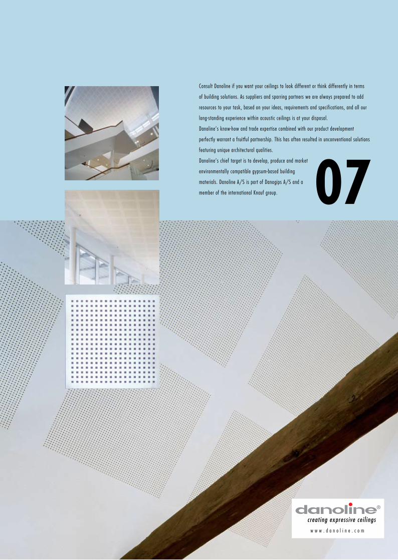
creat ing express ive cei l ings
w w w . d a n o l i n e . c o m
Consult Danoline if you want your ceilings to look different or think differently in terms
of building solutions. As suppliers and sparring partners we are always prepared to add
resources to your task, based on your ideas, requirements and specifications, and all our
long-standing experience within acoustic ceilings is at your disposal.
Danoline’s know-how and trade expertise combined with our product development
perfectly warrant a fruitful partnership. This has often resulted in unconventional solutions
featuring unique architectural qualities.
Danoline’s chief target is to develop, produce and market
environmentally compatible gypsum-based building
materials. Danoline A/S is part of Danogips A/S and a
member of the international Knauf group.
Expressive gypsum ceilings
CI/Sfb: (35)
07