extending the principles of impulse …...international journal on engineering performance-based...
TRANSCRIPT

International Journal on Engineering Performance-Based Fire Codes, Volume 6, Number 2, p.53-71, 2004
53
EXTENDING THE PRINCIPLES OF IMPULSE VENTILATION IN TUNNELS TO APPLY TO SMOKE CONTROL IN CAR PARKS H.P. Morgan International Fire Consultants Ltd, UK B. Vanhove and J-C. De Smedt N.V. International Fire Safety Engineering & Technology S.A., Belgium (Received 23 July 2003; Accepted 24 November 2003) ABSTRACT In the past few years, there have been an increasing number of Impulse Systems installed in car parks, especially in Northern Europe. Unfortunately, no design method has been described openly in the public domain. This places Authorities Having Jurisdiction (AHJs, or Approving Authorities) in a difficult position when faced with a proposal. The present paper is intended to develop calculation procedures which can fill this gap, as well as pointing to aspects needing further research. The paper describes principles and calculation methods for road tunnels, and generalises these to the different geometry typical of open-sided car parks. These principles and calculation methods are then modified to apply to enclosed car park storeys which have an exhaust fan or fans to finally remove smoky gases. The fundamental characteristic of these methods is that fans (jet fans) are used to accelerate the bulk air below the hot sub-ceiling smoke layer to a sufficient velocity to prevent the advance of the leading edge of the smoke layer. The objective is to allow a clear-air safe approach for firefighters from one side of the fire at the cost of a more general smoke-logging beyond the other side. Different formulae for critical bulk air velocities are suggested for flat ceilings; for downstand beams forming channels parallel to the fan jets; and for downstand beams at right angles to the fan jets. A method of relating this critical velocity to the number, size, and emission velocities of the jet fans is suggested. The desirability of matching the final exhaust to the induced bulk airflow is indicated for enclosed car park storeys in order to avoid recirculation of smoke into the area intended to be kept clear. Finally, the need to employ a careful scaling of key parameters in any hot smoke test intended to demonstrate performance of the system is indicated. 1. INTRODUCTION 1.1 Background Smoke Control in above-ground car parks is commonly specified in prescriptive Codes (e.g. Approved Document B to the Building Regulations [1] in the UK). The approach is to specify openings in at least two walls, including two opposite sides of the building, having a minimum free area of a specified percentage of the floor area. In the UK Approved Document B [1] requires a total vent area in the walls of at least 5% with at least 2½ % in each of two opposite walls for the car park to be regarded as open-sided. If the car park is not regarded as open-sided, it should have at least 2.5% total vent area with at least 1¼ % on each of two opposite walls. The latter of the two options attracts
more onerous requirements for fire-resistance rating for the building’s structure than the former. We can note that this method depends on the natural buoyancy of smoke on windless days, and that wind forces can dominate any buoyant forces likely to be found. While it is possible to design Smoke and Heat Exhaust Ventilation Systems for car parks [e.g. 2], the practicality of this approach is greatly influenced by the lack of headroom beneath beams (or ceilings) commonly found in car parks. An alternative method of smoke control has been used in tunnels for many years [3]. This method adopts the principle of “Impulse” or “Jet Fan” ventilation.

International Journal on Engineering Performance-Based Fire Codes
54
1.2 Impulse Ventilation in Tunnels: Qualitative Principles
A fire occurring in a tunnel, for example in a vehicle which has come to a halt, will cause a flame and smoke plume to rise. This plume will reach the roof, and spread outwards in both directions. If the fire is large enough for flame temperature gases to reach the roof, the flames then spreading under the roof cause a rapid increase in heat radiation falling on the fire and on adjacent vehicles, which can lead to a rapid acceleration in growth rate of the fire as it develops and spreads to other vehicles. The hot smoke layer beneath the roof advances at speeds of up to 5 ms-1 for flame temperature gases. Typical vehicle speeds in a road tunnel would be above 30 kph. This corresponds to speeds greater than 5.5 ms-1. It follows that, in a single-bore tunnel with traffic travelling in just one direction, vehicles in front of the vehicle on fire will be able to drive to safety faster than the hot smoke will advance. Vehicles behind the fire will be forced to stop, and will then be at risk from the growing fire (see Fig. 1). In a tunnel where traffic moves in opposite directions in the same bore, vehicles travelling in both directions may become trapped by the fire. There is an aerodynamic interaction between the advancing front of the hot smoke layer and the air in the tunnel. The smoke has to “push aside” the air in front of it, resulting in a resistance to that advance. This process is illustrated in Fig. 2. This
resistance depends on the difference in velocity between the hot smoke and the air. If the bulk velocity of the air in the tunnel is equal to and opposed to the speed at which the hot layer is able to advance in still air, the resultant velocity of advance of the hot smoke will be zero. In other words, inducing a large enough velocity in the bulk air flow will prevent the hot smoky gases from endangering stopped vehicles on the “upstream” side of the fire – i.e. in the direction the bulk air comes from. The turbulence expected at the leading edge (or “nose” if we follow Hinkley’s [4] nomenclature) of the hot smoke will produce a great deal of mixing of smoke and air, causing the tunnel to become smokelogged on the “downstream” side of the fire. Where the vehicle direction of travel is aligned with the bulk air flow this smokelogging will not affect safety (vehicles will have driven clear). There will on the other hand be safe conditions for vehicles trapped by the fire on the “upstream” side, and clear-visibility access for firefighters approaching from the “upstream” side. Smoke control systems using fans to transfer momentum into the bulk air in the tunnel in order to achieve the desired velocity to prevent the advance of hot smoke in the “clean” direction are known as Impulse Ventilation Systems. The fans used to introduce this momentum are commonly known as jet fans, and the concept is often called “Jet Fan Ventilation” as an alternative to “Impulse Ventilation”.
Fig. 1: Impulse ventilation system in a tunnel
Fig. 2: The advance of the leading edge (or “nose”) of a buoyant layer of hot gases

International Journal on Engineering Performance-Based Fire Codes
55
1.3 Impulse Ventilation in Car Parks: Qualitative Principles
The principles developed for tunnels can be applied to the more complicated circumstances of a car park. In the past few years, there have been an increasing number of Impulse Systems installed in car parks, especially in Northern Europe [e.g. 5]. Unfortunately, no design method has been described openly in the public domain. This places Authorities Having Jurisdiction (AHJs, or Approving Authorities) in a difficult position when faced with a proposal. The present paper is intended to develop calculation procedures which can fill this gap. The paper will start by detailing the design methods appropriate to tunnels, and will then generalise these to open-sided car parks. It will then discuss the further aspects of enclosed car parks, pointing to differences in approach compared to open-sided car parks. Finally, there is a brief discussion of acceptance tests for Impulse Systems in car parks. 2. DESIGN OBJECTIVES FOR SMOKE
CONTROL IN A CAR PARK STOREY Smoke control can serve several purposes in a car park. It can ensure that escape routes within the car park storey continue to be usable even while the fire is burning. This objective is therefore to protect the Means of Escape (MoE). In practice, this objective can only be met if escape routes are kept free of smoke to a great enough height for people to move freely in clear air. In most car park designs, this objective is of minor important compared to the provision of suitably short travel distances leading to protected stairs and/or fire exit doors. Smoke control can provide “smoke clearance”. This involves clearing smoke out of the storey after the fire has been suppressed. The objective is to provide good visibility to help firefighters to confirm that there are no secondary fires, and also to speed the reinstatement of the building to normal activity. Between these two extremes, smoke control can assist firefighters in finding and extinguishing the fire. In other words, it can make operational fire fighting faster and more effective, thus reducing damage to the building. This objective does not require as good a performance as for protecting occupants and their escape route, in view of the
special equipment and training available to fire services. Indeed, the smoke control system need not necessarily be activated until firefighters arrive on site. Impulse systems are usually designed to allow firefighters clear access with good visibility to one side of the fire, at the cost of creating turbulent mixing of smoke and air on the other side of the fire, creating extensive smoke logging. It follows that it is usually safer if Impulse Systems are not started while people are evacuating (as they may be caught in the fan-induced smoke logging quicker than with the fans off), but are instead started after a delay comparable to the firefighters attendance time. In practice, a delay of 5 minutes from detection is often used. It may also be noted that many smoke control systems are dual purpose: they operate continuously to dilute engine fumes etc. to safe levels, and change to the (usually) higher ventilation rate needed for smoke control when a fire is detected. A consequence of the previous two paragraphs as far as Impulse Systems are concerned, is that the jet fans may need to be turned off when smoke is first detected, and then turned back on again at the smoke control level after the pre-determined interval. Even though this present paper is based on similarities between tunnel systems and car park systems, it is worth recognising that there are many differences between the two. Some of these are summarised in Table 1. 3. IMPULSE VENTILATION IN
TUNNELS 3.1 Principles Design calculations must first establish the largest fire appropriate for the circumstances. Where the design is based on a steady-state (i.e. on a “worst plausible case”) fire, this can be specified as a heat generation rate coupled with an effective perimeter of the fire. The mass flow rate and temperature of smoky gases reaching the roof close above the fire can then be calculated using established formulae and the known height of the tunnel. The rate of advance of the front edge, or “nose”, of the smoke layer must be assessed. The outcome of this calculation is a critical velocity of advance of the hot smoke layer under the ceiling, for the specified fire in a tunnel of specified height and width.

International Journal on Engineering Performance-Based Fire Codes
56
Table 1: Some typical differences between tunnels and car parks (Note: Many exceptions exist)
Tunnel Car park Aspect ratio (transverse section) Height similar to width Height << width Aspect ratio (long section) Very long compared to width Length similar to width Vehicle movement Unidirectional, at road speeds Multi-directional, at slow speedsVehicle types Mixed. Cars to trucks and buses Cars Typical design fire Truck. > 17 MW Car. About 3 MW Air flow pattern induced by jet fan
Along length of tunnel in direction of traffic flow
Specific to each car park. Ignores traffic movement
Jet fan operation As soon as fire is detected Delay until pedestrian escape is complete
Evacuation patterns for people If ahead of fire, drive on. If behind fire, escape on foot away from fire
Escape on foot via building’s Means of Escape (e.g. protected stairwells)
Fire fighting approach Drive fire appliance into tunnel from air inflow end, as close as possible to the fire
Enter building on foot, approach fire following jet fan-induced airflow
We then need to be able to calculate jet fan characteristics capable of inducing a bulk airflow at least equal but opposite to the smoke layer’s speed of advance in the “upstream” direction. The transfer of momentum from fan jet to bulk air, resulting in the creation of a pressure pushing the air, is discussed below. This pressure has to be sufficient to overcome the pressure losses experienced by the bulk air while travelling through the tunnel. In general, a tunnel will have an entry and an exit opening to the atmosphere. There may be bends or changes in cross-section. There will be friction effects at the walls, floor, and roof. The tunnel is in effect a large duct, similar in most respects to an air-handling duct in a HVAC system in a building. Design information developed for ducts [6] can be used to assess the flow resistance (assessed in terms of pressure losses at each contribution to flow resistance such as entry losses, exit losses, losses at bends, etc.) of the tunnel. The design should be successful when the sum of all the pressure losses, for induced bulk air speeds greater than or equal to the critical “nose” velocity, is equal to the driving pressure induced by the jet fans. This will ensure that the smoke will not be able to advance in the “upstream” direction from the fire. The remainder of Section 3 develops these ideas quantitatively. Wind pressure differences between the entry and the exit to the tunnel can either assist or oppose the flows induced by the jet fans. Daly [3] suggests that such effects should be taken into account. This aspect is not developed further for tunnels in this present paper, although the effect of wind pressures
is considered below in the context of car park Impulse Systems. 3.2 Jet Fan Thrust and Induced Velocities
in Tunnels 3.2.1 Thrust and induced pressure differences
The principles of Impulse or Jet fan ventilation in a single-tube tunnel (or covered roadway) have been described in Section 3.1 above. The present purpose is to develop the mathematical formulae needed to implement a design based on those principles. Equivalent explanations can also be found elsewhere [e.g. 3,7]. One or more fans will be arranged so that they emit jets along the length of the tunnel. These jets should be arranged such that they minimize contact with the roof and walls of the tunnel. It is desirable for the jets to have the maximum opportunity to interact with the air in the tunnel without friction effects slowing the jets before that interaction has occurred. A fan can be characterized as having an emission orifice of area Af m2 and an emission velocity of vf ms-1. The volume flow rate emitted by the fan is:
fff vAV = (1) For ambient temperature air of density ρ0 kgm-3, the mass flow rate of air emitted per second is the product of volume flow rate and density, i.e.: Mf = ρ0 Vf (2)
International Journal on Engineering Performance-Based Fire Codes
57
The total momentum in the air emitted each second (the momentum flux) is simply the product of mass flow rate and velocity, i.e. for a single fan Momentum flux = Mf vf = ρ0 Vf vf (3) For a free jet – that is for a jet which does not interact with resisting solid surfaces such as walls and roof – the total momentum is conserved despite the entrainment of air into that jet. That is, the mass flow rate in the jet increases as air mixes into the jet from the air surrounding the jet; the velocity in the jet decreases, but the product remains constant. Newton’s Second Law also applies to fluids. The rate of change of momentum corresponds to a force. This force, when exerted by a fan is usually called a thrust. In our case, the jets will slow until they become part of the bulk air movement in the tunnel. In other words, the momentum flux emitted per second by the fans is transferred to the air in the tunnel. Hence, the total momentum flux in the bulk air is: ρ0 At vair
2 = ρ0 Vf vf (4) where At is the cross-sectional area of the tunnel at a right angle to the direction of flow of the air. The increase in momentum flux in the bulk air is experienced as a force (Newton’s Second Law) acting on that bulk air volume. It is convenient to recall that a force exerted evenly on a fluid can be expressed as a pressure. It follows then that the rise in pressure above ambient in the tunnel due to one fan is just:
t
airt
AvA
p2
0ρ=∆ (5)
i.e.
t
ff
AvV
p 0ρ=∆ (6)
where there are N fans in the same length of tunnel, we have
t
ff
AvVN
p 0ρ=∆ (7)
This is the impressed pressure difference driving the air through the tunnel, against the resistance of the pressure losses due to bends, surface roughness, etc. These losses are described in more detail in Section 3.2.2 below, and will depend on the design
air velocity which is in turn derived from the speed of the “nose flow” (see below). It is pointed out by Daly [3] that in practice, the impressed pressure is based on the difference between vf and vair. It follows that where greater accuracy is required, vf in equations (1) to (7) should be replaced by (vf – vair). In the present work, this correction is ignored for simplicity, but it can be noted that it can be introduced as a post-hoc correction once the value of vair has been calculated. 3.2.2 Pressure losses in the tunnel
To a good approximation, a tunnel can be regarded as a large duct. Provided that all significant flows are turbulent, that is provided that the Reynolds Numbers are large enough, the difference in scale becomes unimportant, and the resistance to airflow in the tunnel can be calculated by the same methods as in a HVAC or ACMV duct. Methods of calculating resistance to flow are well known. See for example Section 4 of ref. 6. We follow ref. 6 by noting that the energy in fluids moving through ducts is lost in two major ways. One is by frictional interaction with the walls. This can be expressed in D’Arcy’s equation for pressure loss due to friction:
2
2v
Dploss
ρλ l=∆ (8)
where the friction factor λ is a function of Reynolds Number and the relative roughness of the wall surfaces. For further details on how to calculate lossp∆ for a given value of v, via λ and D (the hydraulic mean diameter of the duct/tunnel), see ref. 6 Section 4. The other major source of energy loss (i.e. of pressure loss to overcome resistance to flow) occurs when a bend, obstacle, or other feature generates additional turbulence in the fluid flow. These losses can be expressed in “Pressure Loss Factors” ς defined by:
2
2vploss
ρς=∆ (9)
The pressure loss factor is usually determined empirically, and typically is a shape-dependent function rather than a scale-dependent function. Although it may be necessary to extrapolate (exercising due caution) from an air conditioning duct to a similar geometry tunnel obstruction, many values of ς factors can be found in Section 4 of
International Journal on Engineering Performance-Based Fire Codes
58
Ref. 6. One can note particularly that a tunnel will usually have an entry loss (where air is drawn in one end) and an exit loss (where air and smoke are blown out the other end); plus an additional pressure loss term for each geometrical feature (e.g. bends, changes of cross-section etc.); plus the pressure loss due to friction over its length. Note that where there are significant changes in cross-section or of surface roughness, it will be necessary to calculate the sum of the pressure losses due to friction in each length of tunnel. None of the thermally-buoyant ceiling jet models currently available make allowance for sloping ceilings. Sloping tunnels will affect the entrainment into an inclined buoyant flow, although where the leading edge of that flow is halted close to the fire plume such effects will be minor and can be ignored. There should be minimal effect on the thermal plume rising above the fire. A gradient in the tunnel will have no effect on a non-buoyant flow. It is assumed throughout this paper that the smoke and fire gases become so mixed with air by turbulence on the downstream side of the fire that they can be treated as essentially non-buoyant. It follows that changes in gradient typical of roadways can be ignored. A simple entry (eg. a hole in a wall at right angles to the duct or tunnel) will often have ς = 0.5. A similarly simple exit will have ς = 1.0. Local topographical features will often change these values [7] and tunnel designers may even have to model the surroundings in order to arrive at empirical values appropriate to their circumstances. It is especially important to note that v in equation (9) is the velocity local to that particular obstacle, and changes in cross-section involve changes in local velocity. The volume flow rate (ignoring any heating of the air) will be the same value everywhere. The velocity in D’Arcy’s formula (equation 8) also must be altered for every change in section of the tunnel. In general, a state of dynamic equilibrium will be reached where
2020
22 mm
mm
allmnn
nallt
ffo vdlvp
AvVN ρλρς
ρ∑∑ +=∆=
(10) where all air is assumed to be at ambient temperature; the subscript n denotes separate obstacles, bends, entry, exit or other shape-dependent features such as changes of section; and subscript m denotes individual lengths of tunnel (or duct) having the same cross-section and surface roughness.
In general,
)m,n(t
airm,n A
Vv = (11)
where Vair is the volume flow rate through the tunnel; vn,m is the velocity local to the pressure-loss generating feature identified by subscript n or m, and At(n,m) is the cross-sectional area of the tunnel at the pressure-loss generating feature identified by subscript n or m. This means that for a known geometry of tunnel, one can either specify Vair (as for example where a minimum dilution rate of engine fumes including carbon monoxide must be achieved) or one can specify v (as for example when trying to prevent a thermally buoyant smoke layer travelling against the direction of the fan jets). Then, via equations (10) and (11), the minimum fan specification can be calculated in terms of ff vNV (or 2
ff vNA ).
This immediately shows us that there is a trade-off between the size of each individual fan and the number of fans. 3.3 Opposing the Advance of a Thermally-
buoyant Ceiling Jet of Smoky Gases 3.3.1 General
In Section 3.2, it has been shown that jet fans can induce a bulk flow in the air in a tunnel, determined by many factors including the desired air volume flow rate or air velocity. The designer of an impulse smoke control system must select an appropriate value in order to achieve his objective, which is to ensure that all smoke generated by a fire travels in one direction away from the fire (usually in the direction of traffic movement), leaving the other side of the fire free of smoke. This protects anyone forced to stop; and it allows firefighters to approach the fire in safety, in order to extinguish it. In Section 3.3 of this paper, we discuss how an appropriate value of bulk air velocity can be specified. 3.3.2 The design fire
The fire is likely to be in a vehicle. Usually the designer will be interested in a steady-state design approach. This involves identifying an appropriate heat release rate and fire perimeter (or, for point-source plume models, a fire diameter). From these the initial parameters can be deduced for the thermally-buoyant smoke plume flowing under the ceiling. Useful sources of data on the size of vehicle fires in tunnels are relatively sparse. See Ingerson and Romanov [7] for experimental data including a bus

International Journal on Engineering Performance-Based Fire Codes
59
and truck fires done as part of the EUREKA project. Schleich et al. [8] is a useful source for experimental data on car fires involving modern cars (e.g. Fig. 3). It should be noted that the car design fire cited by Morgan et al. [2] of 3 MW convective heat flux and 12 metres perimeter derives ultimately from 1960s data, but is broadly compatible with Schleich et al.’s results prior to the time when spread to another car is predicted [8].
Fig. 3: RHR vs Time (Source: Prof. J.B. Schleich)
Once a design fire appropriate to the circumstances has been selected, one can use the Large Fire Plume Model to estimate the mass flow rate of hot smoky gases reaching the ceiling [2]:
5.1YPCM e= (12) where M is the mass of smoky gases rising past height Y, Ce is a constant taking the value 0.19 where the fire plume rises vertically to a high smoke layer base; or the value 0.21 where the layer base is close to the fire; or 0.34 where the air approaches the fire from one side and causes the plume to “lean” at an angle to the vertical. P is the fire perimeter and Y is the height of rise. This development of the “Large Fire Plume Model” was by Hansell [9] drawing on work by Zukoski et al. [10] and Quintiere et al. [11] (using “virtual point-source” axisymmetric plumes) to modify the Large Fire Plume Model developed originally by Thomas et al. [12] and Hinkley [13]. As a first approximation, we can take Y to be the height to the roof above the fire. Ce should take a value appropriate to a “leaning plume”, as the purpose is to induce a strong air flow in the tunnel which will inevitably make the plume lean away from the vertical. Hence take
34.0=eC (13)
The average layer temperature close to the plume is then
McQ
=θ (14)
If greater accuracy is required, M, Q and θ can be used to calculate the layer’s depth (see ref. 2, or Hinkley’s method [4] described below); from which one can assess a new Y value, and successive iteration can converge on better values of M and θ. It is suggested that the level of precision implied by iteration cannot usually be justified for car park smoke ventilation in view of the need to introduce safety margins to allow for unquantifiable pressure losses. 3.3.3 Ceiling jets: Established flows
The design of an impulse smoke control system first requires an assessment of the speed of advance of the ceiling jet travelling outwards from the fire – in the absence of an imposed airflow. A ceiling jet is defined in the SFPE Handbook Section 2-4 [14] as being the relatively rapid gas flow in a shallow layer beneath the ceiling surface which is driven by the buoyancy of the hot combustion products. An older usage reserved the term for an under-ceiling layer flow which still carried some kinetic energy from the upward moving gases in the plume above the fire. We can identify two characteristically different forms of flow. One (see Fig. 4) is where the smoke flow has spread under the ceiling until the gases have reached a sink and have been removed. In most experiments, this corresponds to a flow which has reached the edge of the ceiling and is free to spill past it. This is an established flow. The second (see Fig. 5) is where thermally buoyant smoke layers advance beneath a ceiling by displacing the air in front of the “nose” of the smoke layer. This air is effectively pushed downwards by the layer. The energy required to do this comes from the smoke layer and so displacing this air can be regarded as a resistance to the “nose” of the layer flow – an effect absent in a flowing established ceiling jet. The nature of the ceiling jet is also influenced by the geometry of the ceiling. For the purposes of this paper, we can consider two simple circumstances. One is where the buoyant layer (in the absence of any induced cross-wind) flows radially outward under a flat ceiling; the other is where the buoyant layer is confined and channelled between parallel walls or downstand beams.

International Journal on Engineering Performance-Based Fire Codes
60
Fig. 4: An established smoke layer – Smoke flows above cold air
Fig. 5: An advancing smoke layer – Smoke flow displaces downwards the air in front of the leading edge
Formulae for the velocity of advance of an established radial ceiling jet can be found in the SFPE Handbook [14], having been developed by Alpert [15]. These are
31
96.0
=
hQv (15)
for r/h ≤ 0.15, and
65
21
31
195.0
r
hQv = (16)
for r/h > 0.15. Equations (15) and (16) do not require prior calculation of the entrainment into the fire plume, as this is included in the correlation. It can be seen from this correlation that the layer velocity is almost inversely proportional to the radial distance from the point of impingement of
the fire plume on the ceiling. If an Impulse System is to be designed to prevent the advance of the smoke in one direction, the induced airspeed in the opposite direction required to achieve this will be smaller if the smoke is allowed to travel further from the point of impingement. It follows that there can be an implied trade-off between the induced bulk airspeed and the distance the smoke is allowed to travel in the unwanted direction before being halted and turned back. In practical design terms, the maximum smoke travel distance in the unwanted direction can be related to the fire services’ willingness (or otherwise) to tolerate some turbulently mixed smoke in the closest approach to the burning vehicle. It can be noted that radial ceiling jets are unlikely to feature usefully in Impulse system designs for tunnels. They may, however, feature prominently in designs for car parks having extensive flat areas of ceiling. Ceiling jet flows under confined or channelled ceilings are discussed in the SFPE Handbook [14],

International Journal on Engineering Performance-Based Fire Codes
61
although no actual formulae for the layer’s velocity are given. Characteristic velocities for established channelled flows were developed by Morgan and Hansell [16] and are cited in Morgan et al. [2]. They identified the effect of discharge coefficient on the velocity as the hot smoky gases flow beneath downstand beams at right angles to the flow direction: Where the channelled flow has no downstands (i.e. a flat ceiling between the side walls or constraints) the characteristic layer velocity is [2,16]):
31
200
27.1
=
WTcgQTvρ
(17)
Where there are downstands across the flow direction:
31
200
76.0
=
WTcgQTvρ
(18)
In a fully channelled flow, equation (17) will apply over the full length of the channel or tunnel. Equation (18), on the other hand, only applies to the flow as it passes beneath the downstand. In order to apply equations (17) or (18), it is necessary to pre-calculate the layer temperature. This can be done using equations (12) to (14). The depth of the flowing layer (in the absence of a counterflow of air below) is given by Morgan et al. (equation 5.11 of ref. 2) as:
32
5.00
5.0
36.0
=
WTMT
Cd
d θ (19)
where Cd takes the value 1.0 for a flow under a flat ceiling between beams W metres apart, and takes the value of 0.6 for the flow under a deep beam across the direction of flow. In general, because all established flow formulae ignore the resistance to flow at the leading edge or “nose” of the layer, they are likely to predict a higher velocity than will actually be the case at the leading edge of the ceiling jet. In terms of the design of an Impulse system, this will lead to a higher jet fan-induced airspeed to oppose the smoke movement, and the use of such formulae can therefore be expected to err on the side of safety in design. 3.3.4 Ceiling jets: Leading edge or “nose” flows
Hinkley [4] has discussed the speed of advance of the leading edge of a smoke layer (i.e. a ceiling jet)
in a corridor or tunnel, as a part of a study of smoke movement in shopping malls. His work took account of the nose of the ceiling flow explicitly, and so we can expect his work to be the most appropriate source for the present circumstance. Unfortunately he only developed formulae for channelled flows without a downstand across the flow, which serves to limit the applicability of his results. Hinkley [4] has shown (see his equation (16), modified for higher temperature by setting U’= u(T/To)1/3) that the velocity of advance of the “nose” of a layer flow along a tunnel takes the form:
31
2
+
−−=
)dh(h)dh)(dh(
C'Uvnose (20)
where h is the height of the tunnel or channel, d is the buoyant layer depth and
31
2
=
WTcgQT'U
ooρ (21)
where W is the width of the tunnel or channel. Hinkley developed a graphical solution method where one first calculates: ( )
WCUghP′
21
(22)
(making use of equations (12) to (14) above). The depth of the flowing layer is given by Hinkley’s Fig. 4 (reproduced herein as Fig. 6). His Fig. 5 (reproducd here as Fig. 7) gives the dimensionless layer velocity v/U΄C and hence the actual velocity of advance of the leading edge (v). C is an empirical constant found by Hinkley [4] to be approximately 0.5 based on a Japanese experiment in a car park having a complicated geometry. He also speculated that C would tend to 1.0 as the advance of the nose was slowed by an opposing bulk airflow, due to a reduction in friction at the ceiling. We should recognize, however, that flow resistances due to friction at a smooth ceiling are likely to be smaller than those due to displacement of air in front of the “nose” – which would depend on the relative speed of the buoyant layer to the bulk air. Hence C is more likely to be near the empirical value even when the “nose” has zero net speed relative to the ceiling. We can note that he also cited Benjamin as having derived a value for C of 0.82. In practice a higher value for C will lead to a higher value for the critical speed of advance of the “nose” of the

International Journal on Engineering Performance-Based Fire Codes
62
smoke layer, and consequently to a larger jet fan specification, i.e. it will err on the side of safety. It seems reasonable to adopt Benjamin’s value for C for design purposes where Hinkley’s method is adopted. Hinkley’s analysis was for a smoke layer traveling in one direction only away from the fire. Where smoke travels in both directions away from the fire, it is reasonable to take W as being twice the actual width, as the smoke flow is equivalent to a one-direction flow in a tunnel of twice the width.
Fig. 6: Dimensionless layer depth vs dimensionless flow rate, from Hinkley [4]
Fig. 7: Dimensionless velocity vs dimensionless
flow rate, from Hinkley [4]
3.4 Suggested Design Procedure a) Identify an appropriate design fire for the
circumstances.
b) Estimate separately for each length of tunnel having the same width, ceiling height and surface roughness, the layer temperature at the ceiling using Section 3.3.2.
c) Identify the ceiling jet formula appropriate to the circumstances for each separately identifiable length of the tunnel.
d) Calculate the layer velocity for each such length using Section 3.3.3 or 3.3.4. This will be the minimum value of induced velocity acceptable in that length, and can be designated the critical velocity for that length.
e) Calculate the volume flow rate for each length. Take the maximum value as the critical volume flow rate. Recalculate the local velocities corresponding to all lengths and obstacles.
f) Calculate the total pressure losses in the tunnel using these local velocities and Section 3.2.2.
g) Equate this total pressure loss value to the induced pressure due to the jet fans, and calculate the overall fan specification in terms of NVfvf for the tunnel.
3.5 Some Practical Considerations The positioning of jet fans should be such that the jets can transfer momentum to the air without playing on bends or obstacles. The jets should be able to transfer momentum to the air in the tunnel – which implies that a jet fan can be close to an entry blowing inwards, but should never be close to an exit blowing out. It also seems reasonable to have a sufficient horizontal separation along the tunnel for momentum to be transferred before the jet interacts with the next fan downstream. In order to maximise the effect on the smoke layer, the ideal jet fan jet should be angled downwards to avoid contact with the ceiling, and should avoid contact with the walls. 4. IMPULSE VENTILATION IN OPEN-
SIDED CAR PARKS 4.1 General A car park storey can be thought of as a tunnel which is very wide but (usually) with a low ceiling. Where there are openings at opposite sides of the storey, the principles of Impulse ventilation can be applied with little modification – in principle (See Fig. 8). The most important differences between a

International Journal on Engineering Performance-Based Fire Codes
63
tunnel and a car park storey arise from the much greater horizontal extent of the storey. 4.2 Design Objectives Vehicles cannot drive as quickly in a car park as in a road tunnel. There is therefore essentially no opportunity to drive away from the smoke faster than it moves. It follows that Impulse systems in car parks cannot protect escape with the cars. As explained above, they cannot protect the MoE for occupants in view of the turbulent mixing in the direction of the fan jets, and so there is a need for evacuation to be accomplished using travel distances and protected escape stairs etc., before the jet fans are switched on. The primary role of impulse systems in this context is to provide clear access from one side of the fire for firefighters, so that they can control the fire. The system will then provide smoke clearance so that the building can be put back into use as early as possible.
4.3 Opposing Thermally-Buoyant Ceiling Jets
The principles and formulae involved are the same as in Section 3.3 above. The greater horizontal extent of the car park compared to a tunnel, and the lower ceiling, increases the importance of radial ceiling jets (where there is a flat ceiling), and increases the importance of downstand beams where they are present (discussed further in Section 4.4 below). Design of an impulse system can follow a similar sequence to that for tunnels. An appropriate design fire should be selected. This is commonly based on a single car (e.g. 4.5 MW heat release rate, 12 m perimeter cited in ref. 2), with the implicit or explicit assumption that the fire service would be able to intervene before the fire spreads to neighbouring cars (typically this assumes that the firefighters can intervene in the fire in the first 10 to 12 minutes after ignition (see for example Schleich et al. [8]). If attack times are likely to be longer, then perhaps consideration should be given to fitting sprinklers, or assuming a larger design fire.
Fig. 8: Impulse ventilation in an open car park

International Journal on Engineering Performance-Based Fire Codes
64
The selection of a suitable formula for the advance of the ceiling jet is similar to that for a tunnel discussed in Sections 3.3.3 and 3.3.4 above. Where the ceiling is flat, the ceiling jet will be radial, and equations (15) and (16) will apply. Note that the trade-off between an acceptable degree of smokelogging close to the fire on the best line of approach for the firefighters, and the critical velocity of bulk airflow can become a crucial factor in the design. It is recommended that in all such circumstances there should be consultation with the fire service before progressing the design. Where there are relatively deep downstand beams parallel to the jet fan jet directions, either equation (17) or Hinkley’s method (Section 3.3.4 above) will apply when assessing the critical velocity to halt the advance of the smoke layer. The depth of the channelled flow should be calculated (see Sections 3.3.3 and 3.3.4) to confirm whether or not smoke will spill into neighbouring channels. If it will, then the critical velocity becomes less accurate, although the “non-spillage” value can still be adopted as being conservatively safe in the context of calculating jet fan specifications. Where there are beams at a right angle to the jet fan direction, they will act as weirs, spreading the smoke flow laterally until smoke spills across most or all of the available length of the beam. This may be the full width of the car park. This increase in W in equation (19), coupled with the smaller constant for transverse beams, can mean that the critical velocity is much lower for transverse beams than for parallel beams, leading to a smaller specification for the jet fans in the former case. Smoke will tend to spread more widely across the jet fan’s direction with these transverse beams, affecting more of the car park storey. Some car parks have downstand beams in a “criss-cross” pattern. These cannot be calculated by zone model methods, but can be expected to perform somewhere between the parallel and the transverse beam cases. It may be necessary to use more geometry-specific methods based on Computational Fluid Dynamics (CFD) to confirm the performance of Impulse Systems with such ceilings. It should be noted that because the critical velocity, and thus the specified value of NVfvf for the car park storey, is different for the different ceiling configurations, we should not expect designs shown to work acceptably for one ceiling configuration to be as satisfactory for another.
4.4 Balancing Induced Pressure Differences Against Flow Resistances
One can identify an entry pressure loss and an exit pressure loss. In general, the car park storey will be short compared to a typical road tunnel, and the cross sectional area of the car park will usually be large. This means that one could usually ignore the friction losses and base calculations on the shape-dependent pressure losses. The method described in Section 3.4 above can then be used to calculate NVfvf for the storey. Where there are many uncertainties in the calculation (see for example Section 4.5 below), it can be necessary first to develop the zone model methods set out in this paper as an initial proposal, and then use that proposal as a starting point for a more detailed CFD analysis which would either validate the proposal, or which would suggest amendments needed to make the proposal viable. 4.5 Some Practical Design Aspects The greater width of a car park storey relative to its height, when compared with a typical tunnel, makes it more important that the calculated number of fans can exert a uniform pressure on the air across the full width of the storey. If this is not done, the air will tend to move from the region of greater pressure towards the lower, and there will be a circulation pattern of air (and smoke being carried with the air) with some smoke being carried in the undesired direction past the fire into the areas intended to be clear. It may be necessary to specify a larger number of smaller fans to be able to arrange for the spreading jets to be touching the jets to both sides and also the side walls by the distance from the fans where the jet velocities have reduced to the induced air velocity. This may mean that all N fans are used to form one line across the storey, although the non-uniformity across a typical jet implies that it would be better to arrange fans in two lines, with one line covering the “gaps” between fans in the other line (see Fig. 9). In many car parks there are columns, enclosed stairwells, or other constructional features which will generate turbulence in the air flow, but for which there are no known values of ζ. It is also unfortunately the case that there are no ζ values in the available literature for the pressure losses due to air flowing past, around, and under parked cars. Indeed, most current designs of impulse systems appear to ignore the presence of parked cars altogether, and design essentially for an empty car park. There is another practical difficulty where jets play directly onto fixed objects, or onto parked

International Journal on Engineering Performance-Based Fire Codes
65
cars, and some of the momentum in the jet is lost by conversion back into a force on the objects and is therefore not available for raising the induced pressure acting on the bulk airflow. This implies that there are major sources of pressure loss which are unquantifiable in most cases. These can be compensated for by increasing the number of fans. It appears usually necessary in such cases to adopt a subjectively assessed safety margin – e.g. by doubling the number of lines of jet fans calculated as being necessary based on the known pressure loss terms. Where downstand beams form channels, there is a tendency for both the ceiling jet (smoke) and the fan jet to be attracted to the ceiling by the Coanda effect (i.e. where the static pressure is reduced because of the gas velocity – a demonstration of Bernouilli’s Equation). This may interfere with the transfer of momentum from jet to air to allow air to recirculate past the fans in channels between the fans. It may be necessary to mount a fan in each channel – although this is often not practical. More research is needed to study this effect and to identify whether the problem exists and if so how it can best be overcome. If the induced velocity at the inlet opening is too high, the incoming air jet will entrain air inside the car park. This can cause a recirculation pattern which may bring smoke past the jet fans into the
area we wish to be kept clear. Similar concerns affect Smoke and Heat Exhaust Ventilation Systems, for which the recommendation for air inflows close to smoke [2] is that the incoming jet should not exceed 1 ms-1. Research into the significance of this effect would be desirable. Wind pressures on the inlet and exit openings can be much larger than the pressures induced by the fans. A commonly recommended approach is to use reversible jet fans, with the direction of their operation linked to wind direction sensors such that the wind-induced airflow in the car park is always in the same direction as the fan jets. Jet fans can be used additional to the calculated lines, to direct or “steer” flows of air and smoke within the car park. The purpose is to make bulk air flows more homogeneous even where the car park geometry is complicated. It would usually be necessary to use a CFD model to confirm the effectiveness of the proposal. CFD modellers should note the importance of properly modelling the structure of the jets issuing from jet fans. Suppliers should note the importance of making such details available to modellers. Simply assuming that the jet from a fan is one-dimensional risks being very misleading. CFD modellers should also note the critical importance of mesh size when modelling flows around beams.
Fig. 9: Staggered implementation of jet fan lines

International Journal on Engineering Performance-Based Fire Codes
66
Because the impulse system effectively guarantees smokelogging in the down stream direction, it is important that the system should be fully integrated with other fire protection measures. It has already been noted that systems should not be initiated until a safe time after detection which will allow people to have evacuated from the car park. This carries an implied need for a good smoke detection system to give warning as early as possible. It also implies that the alerting process be effective, and compatible with people perhaps being inside well-soundproofed cars. This suggests the need for eye-catching flashing lights to draw attention to written messages. In view of the difficulty in driving to safety, the messages should advise people to evacuate on foot by the nearest fire exit, leaving their cars where they are. Protected evacuation stairwells which connect to the smokelogged areas of the storey risk permitting smoke to enter the stairshaft, perhaps with the leakage rate increased by the local pressure rise due to a fan jet directed towards the stairwell door. Even though evacuation should be complete before the jet fans start, and even though firefighters should be directed towards a clear area of the car park storey as a part of their approach to the fire, caution suggests that doors from the car park to the protected shaft should be fitted with smoke seals to minimise any such leakage. 5. IMPULSE VENTILATION IN
ENCLOSED CAR PARKS 5.1 Comparison with Open-Sided Car
Parks The key difference between an open-sided car park and an enclosed car park is that the air inlet and air
exit openings in the former are natural openings; whereas the exhaust from the latter takes the form of an exhaust fan or fans (see Fig. 10 and compare with Fig. 8). It is usual even in enclosed car parks for some or all of the incoming air to enter the car park through natural openings, although systems can also be designed with fans supplying air as well as exhausting air and smoke. The fan exhaust has the effect of making the system much less sensitive to wind pressures, and reduces or eliminates the need for the system to be designed to be bidirectional depending on wind direction. The exhaust rate is determined by the capacity of the exhaust fans. Conservation of mass means that the air entering the inlets has an equal mass flow rate to the exhaust. If we ignore the heating due to a fire, this means that the volume flow rate entering the car park storey is equal to the exhaust rate. This also implies that the net volume flow rate through the car park storey has this same value – regardless of what any jet fans are doing inside the storey. In practice, this means that the bulk air velocity needed to halt the advance of the thermally-buoyant ceiling jet beneath the storey’s accent is determined by the exhaust fans, while the jet fans serve to “steer” the air flows within the storey in order to achieve a more uniform flow and to achieve the same effect on the ceiling jet wherever the fire occurs across the width of the storey. The effect of downstand beams, and of excessive airspeeds at air inlets, are the same as for the open-sided car park storey.
Fig. 10: Impulse ventilation in an enclosed car park with exhaust fans

International Journal on Engineering Performance-Based Fire Codes
67
It is still necessary to estimate the number of jet fans required for the car storey. The pressure loss at the storey inlet is more appropriately considered as a part of the exhaust fan’s exhaust duct design calculation, and need not be considered further herein. Similarly, the pressure losses at the exhaust fans’ intakes can be considered as a part of the loss calculation for the exhaust duct. The calculation of the critical ceiling jet velocity, and hence of the critical bulk air flow rate, is the same as detailed in Sections 3 and 4 above. The relation between the jet fan specification NVfvf and the momentum in the bulk air flow (equation (4) above) can be adopted as a first approximation to the jet fan specification. This jet fan specification can be expressed as one or more lines of fans across the desired direction of smoke movement, as discussed in Section 4 above. There will be many unknown sources of pressure loss, especially when there are vehicles present in the car park, and as in Section 4 it is desirable to design at least one more line of fans than calculations indicate. This inherent uncertainty in these zone model methods makes it very important that the design should be validated by a thorough CFD model of the storey, and perhaps amended in the light of the results. Note here that the primary role of the initial zone model-based design is to provide a reasonably-plausible basis for initial discussions, and to reduce the number, duration, and hence cost of the CFD runs required. 5.2 Some Practical Considerations If the induced bulk air volume flow rate in the storey is much smaller than the exhaust fan/s volume flow rate, one expects the exhaust to dominate the pattern of air movement within the storey. The effect would be to reduce the effectiveness of the jet fans in creating a uniform flow along the storey. This makes it more likely that smoke can move in the undesired direction where the induced air velocity is locally less than the critical velocity of the leading edge of the ceiling jet. The positive aspect of this is that if the inlets and the exhausts are evenly distributed across opposite walls of a rectangular-plan storey, and the volume flow rate is greater than the critical value, the benefits of impulse ventilation can be obtained with no jet fans at all! Unfortunately, few enclosed storeys have such an ideal geometry. If the induced bulk air volume flow rate is greater than the exhaust volume flow rate, the discrepancy between what is being “pushed” towards the exhaust and what is being removed by the exhaust must somehow travel back past the fans to become available at the fan inlets. This can either take the
form of a recirculation pattern throughout the storey, causing smoke to affect the areas intended to be kept clear, or it can take the form of a local recirculation at each fan, which would have less of an adverse effect on the performance of the impulse system. The significance of these recirculation patterns cannot be assessed by zone-model methods, but should be revealed by CFD modelling. The ideal design will have the bulk airflow induced within the storey equal to the exhaust volume flow rate, in which case there should be no opportunity for adverse recirculation. One can note, however, that the balance point between induced and exhaust volume flow rates may be changed by changing the numbers of cars in the storey. Research into the significance of this effect would be highly desirable. The importance of avoiding excessively fast jets of air entering the storey through inlets of small area is essentially the same as discussed in Section 4 above. The adverse effect, as in Section 4, is that entrainment into the air jet inside the inlet can itself drive a recirculation of smoky air which can overcome the “steering” effect of the jet fans. Many enclosed car parks are multi-storey, with vehicle access ramps connecting the storeys. These ramps can often result in a complicated pattern of air flows. This can often be used to advantage in providing make-up air naturally into the fire-storey, although success in integrating this into the overall design depends strongly on the actual geometry of the building. It is crucially important that the spread of smoke through the car park be restricted; in particular it is important that smoke should be prevented from spreading through the vehicle access ramps from one storey to another. The possibility of a fire in a vehicle on one of the ramps must also be considered. Preventing smoke spread between storeys needs to be a primary design objective of the Impulse Ventilation System. In many circumstances, it may prove a more convenient option to use a Smoke and Heat Exhaust Ventilation System (SHEVS) concept to contain buoyant smoke and prevent it moving into the access ramp area. The design of such a SHEVS is outside the scope of this present paper: we can however note that in a large and complex car park, it may be appropriate to mix several different design concepts in different areas provided that they are complementary and do not interfere adversely with each other.
International Journal on Engineering Performance-Based Fire Codes
68
6. ACCEPTANCE TESTS OF INSTALLED IMPULSE VENTILA-TION SYSTEMS
Where a full test of the installed system is required to confirm the satisfactory operation of an impulse system, one can either do an essentially “cold” test to confirm that all items of the system perform to their individual specifications (which unfortunately does not confirm the performance of the system when there is an actual fire), or one can conduct a Hot Smoke Test. The latter can either burn a car-sized fire, with the inevitable additional repair and cleaning costs for the storey, or one can use a scaled Hot Smoke Test. The use of scaling relationships to create the same observed performance as an actual full-size design fire but without damaging the building, has been developed by Morgan and De Smedt [17]. The conclusions from their paper can be summarised as follows: a) Without adopting a fire tray pattern which
corresponds to the scaling relationships in the gas flows, the observed smoke depths and/or distances travelled by smoke will not correspond to the design predictions.
b) Where fans are present, their exhaust velocities need to be altered to conform to the scaling relationships in the gas flows, otherwise the observed smoke depths and/or distances travelled by smoke will not correspond to the design predictions.
c) Unless scaling is taken into account when specifying the hot smoke test fire and any fans involved, the full design performance of a smoke control system cannot be properly assessed.
d) The exception to a) to c) above is when the same calculation procedure has been used for both the design condition and for the hot smoke test, and is fully appropriate to both conditions. In this case, a good match between prediction and observation for the hot smoke test gives confidence in the application of the calculation procedure to the design condition.
NOMENCLATURE Af cross-sectional area of emitting orifice of a
fan, m2 tA cross-sectional area of a tunnel (or, by
analogy, of a car park storey), m2 c specific heat of air at constant pressure, kW
kg-1K-1 C an empirical constant used in Hinkley’s
method for “nose” flows Cd a discharge coefficient
Ce the dimensioned entrainment constant in the Large Fire Plume Model, kg m-5/2s-1
d depth below ceiling of a thermally-buoyant smoke layer, m
D hydraulic mean depth (i.e. effective diameter of a non-circular duct or tunnel), m
g acceleration due to gravity, ms-2 l length of tunnel having similar cross-section
and smoothness, m m the subscript m denotes individual lengths of
tunnel (or duct) having the same cross-section and surface roughness
M mass flow rate of gases, kg s-1 Mf mass flow rate of air emitted from the fan
orifice, Kgs-1
n the subscript n denotes separate obstacles, bends, entry, exit or other shape-dependent features such as changes of section
N number of fans predicted as the minimum necessary for a tunnel or car park storey
P perimeter of fire, m Q convective heat flow in the gases due to the
fire, kW r radial distance from the centre of the
axisymmetric plume impinging on a flat ceiling, m
T absolute temperature of smoky gases, K T0 absolute ambient temperature, K u velocity of leading edge of a “nose” flow
(Hinkley), ms-1 U ′ leading edge velocity corrected by Hinkley
to allow for higher gas temperatures, ms-1 v gas velocity, ms-1
airv velocity of air in the tunnel or car park storey, ms-1
fv velocity of air emitted by a fan, ms-1
airV volume flow rate of air in a tunnel or car park storey, m3s-1
Vf volume flow rate of air emitted by a fan, m3s-1
W width of a flowing smoke layer, measured normal to that flow, m
Y height from the base of the fire to the base of the hot smoke layer, m
p∆ a pressure difference (e.g. impressed by the momentum of a fan jet), Pa
lossp∆ a pressure loss due to either friction or turbulent energy losses in the air flow, Pa
ζ a zeta-factor: a shape-dependent factor relating pressure losses to flow velocity
θ temperature of gases above ambient, K λ friction coefficient ρ a gas density, kgm-3
0ρ density of ambient air, kgm-3

International Journal on Engineering Performance-Based Fire Codes
69
REFERENCES 1. The Building Regulations 2000, Fire safety,
Approved Document B, Department of the Environment, Transport and Regions, London, (2002).
2. H.P. Morgan, B.K. Ghosh, G. Garrad, R. Pamlitschka, J-C. De Smedt and L.R. Schoonbaert, “Design methodologies for smoke and heat exhaust ventilation”, BR 368, CRC, London (1999).
3. B.B. Daly, Woods practical guide to fan engineering, Chapter 13 Ventilation of tunnels and mines, 6th edition, Woods of Colchester, Colchester, UK (1992).
4. P.L Hinkley, “The flow of hot gases along an enclosed shopping mall - A tentative theory”, Fire Research Note 807, FRS (Now part of BRE, Garston, UK) (1970).
5. R. van Beek and G. Dons, “No smoking”, Fire Prevention and Fire Engineers Journal, Vol. 63, pp. 29-31 (2003).
6. CIBSE Guide C, Reference data, Section 4 - Flow of fluids in pipes and ducts, The Chartered Institute of Building Services Engineers, London (2001).
7. H Ingason and L Romanov, “Use of mobile fans in tunnels”, SP Swedish National Testing and Research Institute, SP Report 2002:06 (2002).
8. J.B. Schleich, L.G. Cajot and D. Joyeux, “Natural fires in closed car parks”, Eurofire 99, Brussels, (1999).
9. G.O. Hansell, “Heat and mass transfer process affecting smoke control in atrium buildings”, PhD Thesis, South Bank University, London (1993).
10. E.E. Zukoski, T. Kubota and B. Cetegan, “Entrainment in fire plumes”, Fire Safety Journal, Vol. 3, pp. 107 (1981).
11. J.G. Quintiere, W.J. Rinkinen and W.W. Jones, “The effects of room openings on fire plume entrainment”, Combustion Science and Technology, Vol. 26, No. 5-6, pp. 193-201 (1981).
12. P.H. Thomas, P.L. Hinkley, C.R. Theobald and D.L. Simms, “Investigation into the flow of hot gases in roof venting”, Fire Research Technical Paper No. 7, London, The Stationary Office (1963).
13. P.L. Hinkley, “Rates of production of hot gases in roof venting experiments”, Fire Safety Journal, Vol. 10, pp. 57-65 (1986).
14. D.D. Evans, SFPE Handbook of Fire Protection Engineering, 2nd edition, Section 2, Chapter 4 -Ceiling jet flows, The National Fire Protection Association, USA (1995).
15. R.L. Alpert, “Calculation of response time of ceiling-mounted fire detectors”, Fire Technology, Vol. 8, pp. 181-195 (1972).
16. H.P. Morgan and G.O. Hansell, “Atrium buildings: Calculating smoke flows in atria for smoke control
design”, Fire Safety Journal, Vol. 12, No. 1, pp. 9-35 (1987).
17. H.P. Morgan and J-C. De Smedt, “Hot smoke tests: Testing the design performance of smoke and heat ventilation systems and of impulse systems”, FireAsia 2003 “A safe city in motion”, Hong Kong, 26-28 February (2003).
WORKED EXAMPLE In this example, we look at a simple rectangular car park storey with a flat ceiling. The dimensions are not intended to represent a fully realistic design, but are solely intended to illustrate the principles. The car park storey is 50 m wide, 75 m long and has a height of 3.20 m. Both of the shorter sides are open for the full height, through the full width. This implies a typical entry coefficient of 0.5, and a typical exit coefficient of 1.0 by analogy with duct flows. The objective is to design an impulse ventilation system for this car park storey. The design fire has a convective heat flux of 6 MW and a perimeter of 12 m. This represents a very severe single car fire. For a real case, the design fire has to be chosen very carefully in correspondence to the given circumstances. While dimensioning the jet fan installation, we shall assume that this installation must stop the spread of smoke within 15 m on the “upstream” side of the design fire. The car park has a flat ceiling which implies a radial spread of the ceiling jet. In the calculation, the following procedure is applied: Stage 1: Calculation of r/h r is the radial distance from the centre of the axisymmetric plume impinging on a flat ceiling, and h is the height of the car parking. It can be seen from equations (15) and (16) that we need to identify whether
15.0≥hr
For the present example, r = 15 m h = 3.20 m From which we obtain: r/h = 4.7 > 0.15

International Journal on Engineering Performance-Based Fire Codes
70
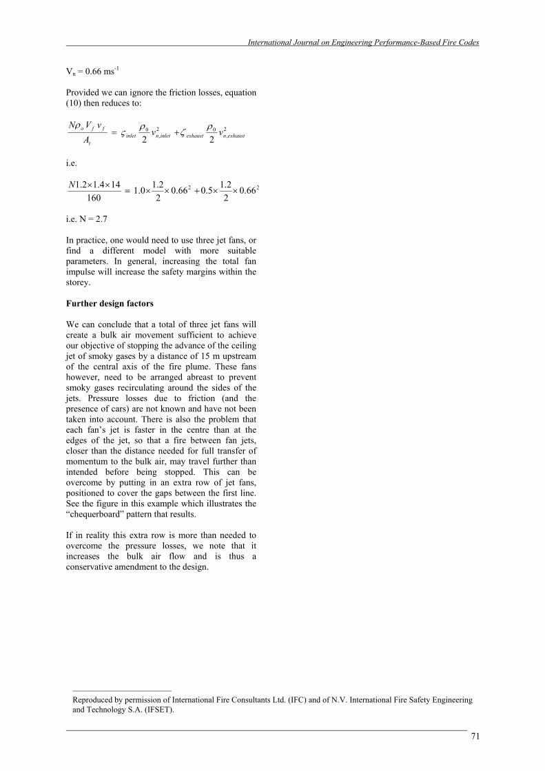
Example figure: “Chequerboard pattern” jet fans in an open-sided car park Stage 2: Calculation of the velocity of the ceiling jet in the car park storey vceiling jet (ms-1) Because r/h > 0.15 => we must use equation (16):
65
21
31
195.0
r
hQcj =ν
For the present example, Q = 6 MW h = 3.20 m r = 15 m From which we obtain: vceiling jet = 0.66 ms-1 Stage 3: Calculation of the cross-sectional area of the car park storey At (m²) This means the cross-section at a right angle to the direction of the induced bulk air flow:
bhAt = For the present example, b = 50 m h = 3.20 m From which we obtain: At = 160 m²
Stage 4: Calculation of the critical volume flow rate through the storey (and the velocity at the openings) The critical volume flow rate is just the product of the calculated critical velocity (Stage 2 above) and the cross-sectional area (Stage 3 above). i.e. Vair = vceiling jet At For this example, Vair = 0.66 x 160 = 105.6 m3s-1 Stage 5: Specification of the characteristics of the jet fans In practice, the designer must choose between available fan types and sizes. For this example, assume that fans are available with the following characteristics (Note: It should not be assumed that actually available fans will have these characteristic parameters): Vf is the volume flow rate of air emitted by a fan = 1.4 m³s-1, and vf is the velocity of air emitted by a fan = 14 ms-1. Stage 6: Calculation of the number of jet fans N We need to implement equation (10). The local velocity in the inlet opening is equal to that within the storey, because the opening is full height. The same is true of the exhaust opening. Therefore the local velocity at the “obstacle” represented by each opening is:
International Journal on Engineering Performance-Based Fire Codes
71
Vn = 0.66 ms-1 Provided we can ignore the friction losses, equation (10) then reduces to:
2,
02,
0
22 exhaustnexhaustinletninlett
ffo vvA
vVN ρζ
ρς
ρ+=
i.e.
22 66.022.15.066.0
22.10.1
160144.12.1
××+××=××N
i.e. N = 2.7 In practice, one would need to use three jet fans, or find a different model with more suitable parameters. In general, increasing the total fan impulse will increase the safety margins within the storey. Further design factors We can conclude that a total of three jet fans will create a bulk air movement sufficient to achieve our objective of stopping the advance of the ceiling jet of smoky gases by a distance of 15 m upstream of the central axis of the fire plume. These fans however, need to be arranged abreast to prevent smoky gases recirculating around the sides of the jets. Pressure losses due to friction (and the presence of cars) are not known and have not been taken into account. There is also the problem that each fan’s jet is faster in the centre than at the edges of the jet, so that a fire between fan jets, closer than the distance needed for full transfer of momentum to the bulk air, may travel further than intended before being stopped. This can be overcome by putting in an extra row of jet fans, positioned to cover the gaps between the first line. See the figure in this example which illustrates the “chequerboard” pattern that results. If in reality this extra row is more than needed to overcome the pressure losses, we note that it increases the bulk air flow and is thus a conservative amendment to the design.
________________________ Reproduced by permission of International Fire Consultants Ltd. (IFC) and of N.V. International Fire Safety Engineering and Technology S.A. (IFSET).