extension of the blt equation to incorporate ... · extension of the blt equation to incorporate...
TRANSCRIPT

Extension of the BLT Equation to Incorporate Electromagnetic Field Propagation
Fredrick M. Tesche Chalmers M. Butler
Holcombe Department of Electrical and Computer Engineering 336 Fluor Daniel EIB
Clemson University, Clemson, SC 29634-0915 USA
This research was supported by the U.S. Department of Defense
under MURI grant F49620-01-1-0436 to University of Illinois at Chicago
and Clemson University
University of Houston University of Illinois at Urbana-Champaign
University of Michigan
June 8, 2002
CLEMSON UNIVERSITY

Report Documentation Page Form Approved OMB No. 0704-0188
Public reporting burden for the collection of information is estimated to average 1 hour per response, including the time for reviewing instructions, searching existing data sources, gathering and maintaining the data needed, and completing and reviewing the collection of information. Send comments regarding this burden estimate or any other aspect of this collection of information, including suggestions for reducing this burden, to Washington Headquarters Services, Directorate for Information Operations and Reports, 1215 Jefferson Davis Highway, Suite 1204, Arlington VA 22202-4302. Respondents should be aware that notwithstanding any other provision of law, no person shall be subject to a penalty for failing to comply with a collection of information if it does not display a currently valid OMB control number.
1. REPORT DATE
JUN 2002 2. REPORT TYPE
N/A 3. DATES COVERED
4. TITLE AND SUBTITLE
Extension of the BLT Equation to Incorporate Electromagnetic Field Propagation
5a. CONTRACT NUMBER
5b. GRANT NUMBER
5c. PROGRAM ELEMENT NUMBER
6. AUTHOR(S) 5d. PROJECT NUMBER
5e. TASK NUMBER
5f. WORK UNIT NUMBER
7. PERFORMING ORGANIZATION NAME(S) AND ADDRESS(ES)
Clemson University, Clemson, SC 29634-0915 USA 8. PERFORMING ORGANIZATION REPORT NUMBER
9. SPONSORING/MONITORING AGENCY NAME(S) AND ADDRESS(ES) 10. SPONSOR/MONITOR'S ACRONYM(S)
11. SPONSOR/MONITOR'S REPORT NUMBER(S)
12. DISTRIBUTION/AVAILABILITY STATEMENT
Approved for public release, distribution unlimited
13. SUPPLEMENTARY NOTES
Presentations given at the First Annual Review Meeting on June 8, 2002 DoD MURI Award F49620-01-1-0436, The original document contains color images.
14. ABSTRACT
15. SUBJECT TERMS
16. SECURITY CLASSIFICATION OF:
a. REPORT
unclassified b. ABSTRACT
unclassified
17. LIMITATION OF ABSTRACT
c. THIS PAGE
unclassified UU
18. NUMBER OF PAGES
17
19a. NAME OF RESPONSIBLE PERSON
Standard Form 298 (Rev. 8-98) Prescribed by ANSI Std Z39-18
Outline of Presentation
Introduction
Review of the Derivation of the BLT Equation
Extension of the BLT Equation
Summary
Extension of the BLT Equation - Slide 2/17 £ ,EMSON L S I V E R S I T Y

Overview
The BLT equation for analyzing transmission line networks permits a system-level analysis of the EM effects on large systems
-This is the basis of the CRIPTE code, and its predecessor, QV7TA
In this MURI effort, we wish to extend the formulation of the BLT equation to take into account the following: -EM field propagation and coupling to the network -EM penetration through apertures -EM scattering from nearby bodies (including cavities)
Extension of the BLT Equation - Slide 3/17 £ EMSON L S I V E R S I T Y

Illustration of BLT Equation Extension
We wish to include non-conducting paths in the interaction sequence diagram
-To model aperture or diffusive penetrations New, non-conductive BLT interaction path
Conventional BLT conducting interaction path
Extension of the BLT Equation - Slide 4/17 CLEMSON l s I h t I T V

Outline of Presentation
Motivation
Review of the BLTEquation
Extension of the BLT Equation
Summary
Extension of the BLT Equation - Slide 5/17 £ ,EMSON L S I V E R S I T Y

The BLT Equation for a Single Line Network
Consider a single transmission line "network" The BLT Equation provides the voltage or current responses at the ends (junctions) of the line
Transmission Line
This is done b^ incident and n
And including the excitation of forward and backward traveling wave components on the line by the excitation sources.
Vi z Linear Graph XX
Forward traveling wave -w> V+(x)
V1
Node #1
ref <^- \T(x)
Backward traveling wave
X)
Excitation
v2ref
Node #2
Extension of the BLT Equation - Slide 6/17 CLEMSON L S I V I R S I T Y
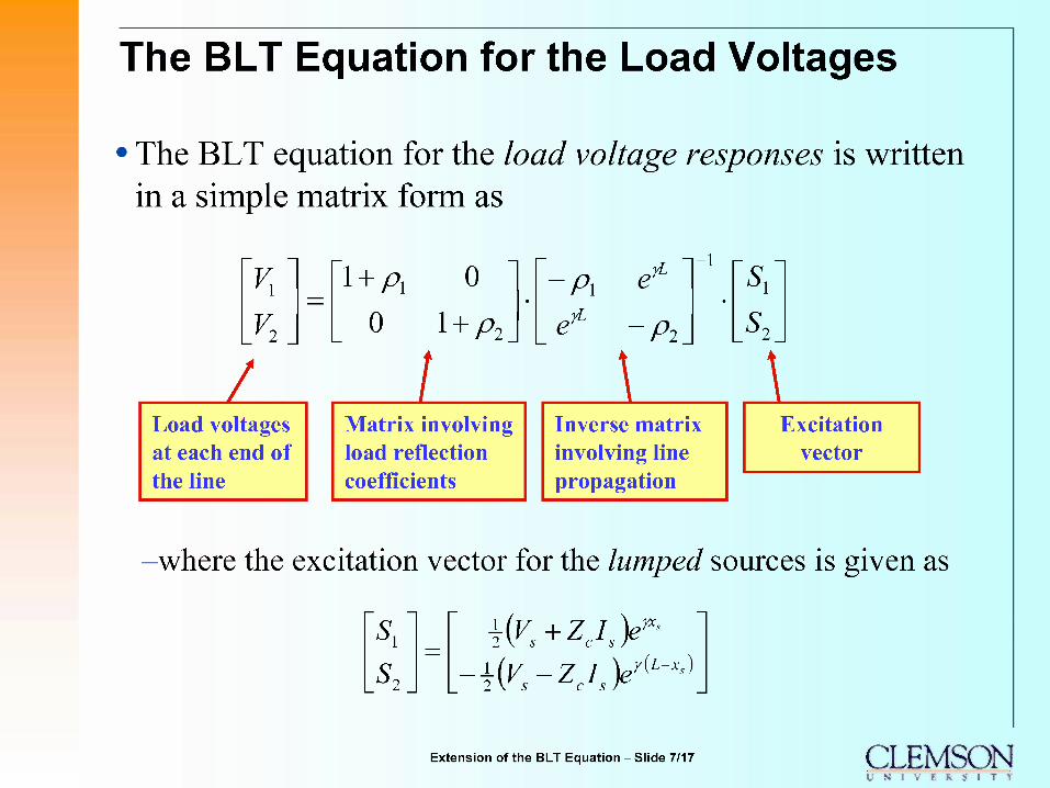
The BLT Equation for the Load Voltages
• The BLT equation for the load voltage responses is written in a simple matrix form as
1 + A 0 0 \ + p2
A
Z Load voltages at each end of the line
l Matrix involving load reflection coefficients
i fi
A
-i r- 5,
Inverse matrix involving line propagation
i Excitation
vector
-where the excitation vector for the lumped sources is given as
S,
±(v8+zei8y- -±(vs-zcisy^s)
Extension of the BLT Equation - Slide 7/17 CLEMSON L S I V I R S I T Y

The BLT Equation for Incident Field Excitation
.incjfC incident Field Excitation
%-
j± Distributed Voltage Sources
inc EL,(0)
t d
I
<v
<£
inc 2 \
» The BLT equation for a lumped voltage source can be viewed as a Green 's function
-The response is found by integrating over the line to incorporate the tangential E-field excitation of the line.
• The same functional form of the BLT equation is valid for incident field (plane-wave) excitation:
l + A 0
0
l + A A JL
A
S, S^
Only a change in the source vector is necessary:
Eincd (eJkL(l-cosy/) _ A
eßL | -jkL(\+cosi//) "l)J = E inc
F2{Y)
Note the field coupling functions Fj and F2
Extension of the BLT Equation - Slide 8/17 CLEMSON l s I h t I T V
Outline of Presentation
Motivation
Review of the Derivation of the BLT Equation
Extension of the BLT Equation
Summary
Extension of the BLT Equation - Slide 9/17 £ ,EMSON L S I V E R S I T Y
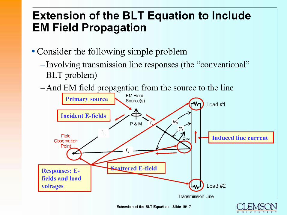
Extension of the BLT Equation to Include EM Field Propagation
• Consider the following simple problem
-Involving transmission line responses (the "conventional" BLT problem)
-And EM field propagation from the source to the line Primary source
EM Field Source(s)
Incident E-fields
Field Observation
Point
Responses: E- fields and load voltages
Load #1
Induced line current
Load #2
Transmission Line
Extension of the BLT Equation - Slide 10/17 £ ,EMSON l S I V l R S 1 T V

Extension of the BLT Equation (con't.)
We define a signal flow granh including both the transmiss "Regular" nodes where the
incident and reflected waves are n coefficient.
Incident and reflected voltage waves at the transmission line ends
<| rioflE
ing paths
Node 2
Node 3
Node 4
i...................
ransmission line "tube"
Incident and reflected E- fields at the ends of the EM field propagation path
Tubel
Node 1
Extension of the BLT Equation -Slide 11/17 CLEMSON L S I V I R S I T Y
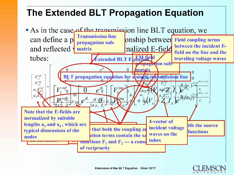
The Extended BLT Propagation Equation
As in the case.^f thp trqngmk^ion line BLT equation, we Transmission line can define a p
and reflected tubes:
propagation sub matrix
onship betweei lized E-:
Field coupling terms between the incident E- field on the line and the traveling voltage waves
Note that the E-fields are normalized by suitable lengths a3 and a4, which are typical dimensions of the nodes "I ^rr^^rr^r^vna^ji^
,ß(ro-rs)
that both the coupling ai incident voltage ition terms contain the sa waves on the
nmctions Fj and F2 — a const
4-vector of
tubes
of reciprocity
ith the source functions
Extension of the BLT Equation - Slide 12/17 CLEMSON l s I h $ I T V
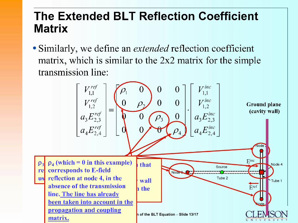
The Extended BLT Reflection Coefficient Matrix
Similarly, we define an extended reflection coefficient matrix, which is similar to the 2x2 matrix for the simple transmission line:
P3 re us
T/ref *A (n
T/ref '1,2 vO Py
a3h23 0 | a Fref 0/
p4 (which = 0 in this example) corresponds to E-field reflection at node 4, in the absence of the transmission line. The line has already been taken into account in the propagation and coupling matrix.
Ground plane (cavity wall)
Node 4
Tubel
CLENISON l N I V E R S I T Y
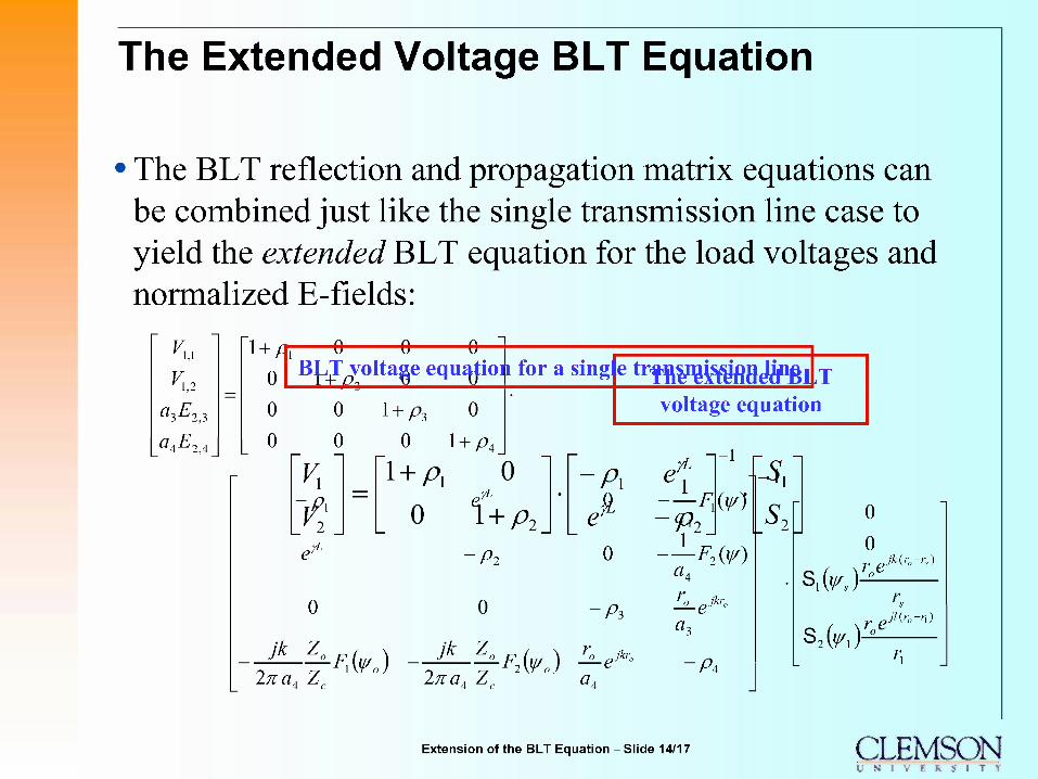
The Extended Voltage BLT Equation
The BLT reflection and propagation matrix equations can be combined just like the single transmission line case to yield the extended BLT equation for the load voltages and normalized E-fields:
vt 1,1
a3h23
Cl^-L-i2 4
1 + /T 0
0 0 0 BLT voltage equation for a sing
0
0
0
0
\+p3 0
?rL
0 0 1 + A
"1 + A
0 \ + p2
-Pi
o
jk z 2naA Zc
-Ffoo)
0
jk z
etrfne^MMeVPßl/r
A
o
-A
2n;aA Z °-F2(¥o) ^e^
voltage equation
1
-<p2 W
—F2(¥) aA
a. Jkro
A
o 0 re s,k)^
jk(r0-rs)
s2W roe ß(r0-n)
Extension of the BLT Equation - Slide 14/17 CLEMSON l s I h $ I T V
Outline of Presentation
Motivation
Review of the Derivation of the BLT Equation
Extension of the BLT Equation
Summary
Extension of the BLT Equation - Slide 15/17 £ ,EMSON L S I V E R S I T Y

Summary
A modified BLT equation, taking into account EM field propagation paths in addition to the usual transmission line propagation mechanisms, has been developed.
-This required modifying the BLT propagation matrix to include the field coupling to the transmission line and the EM scattering from the line.
-These features have been illustrated with a very simple example.
The next step in this development will be to include the more general case of EM shields with apertures, and multiple field paths, as shown in the next slide
Extension of the BLT Equation - Slide 16/17 £ EMSON L S I V E R S I T Y
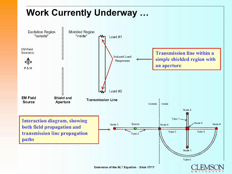
Work Currently Underway...
Excitation Region "outside"
EM Field Source(s)
4> P&M
Shielded Region "inside" v^n Load #1
Induced Load Responses
Transmission line within a simple shielded region with an aperture
EM Field Source
Shield and Aperture
-^J Load #2
Transmission Line Outside
Interaction diagram, showing both field propagation and transmission line propagation paths
Node 3 Source
Tube 2
Inside
Node 2
Tube 1 •
Node 4 Node 5 Node 6
Tube 3 Tube 4
Node 1 ../'
Tube 5
Extension of the BLT Equation - Slide 17/17 CLEMSON l s I h t I T V