exterity avediaplayer r92xx series v2 - netvue r92xx series v2.0 administrator‟s guide 7 1 summary...
TRANSCRIPT
Exterity AvediaPlayer r92xx series V2.0
Administrator’s Guide
AvediaPlayer r92xx series V2.0
2 Administrator‟s Guide
Notices
© Exterity Limited 2003-2011
This document contains information that is protected by copyright. Reproduction, adaptation, or translation without prior permission is prohibited, except as under the copyright laws.
Document Reference
1300-0024-0001
Edition
2.0 Release 1 (November 2011)
Printed in UK Exterity Limited Ridge Way Hillend Industrial Park Dalgety Bay, Fife, KY11 9JD Scotland, UK http://www.exterity.com
Products Described By This Guide
AvediaPlayer r9200
AvediaPlayer r9210
AvediaPlayer r9220
Trademarks
The Exterity building IPTV logo, in-Socket Technology, prodaptor, AvediaServer, AvediaPlayer, AvediaCentre and iSocket are trademarks or registered trademarks of Exterity Limited.
Microsoft®, Windows
®, and Windows Media
Player® are U.S. registered trademarks of
Microsoft Corporation.
HDMI, the HDMI Logo and High-Definition Multimedia Interface are trademarks or registered trademarks of HDMI Licensing LLC.
Kensington® is a U.S. registered trademarks of
ACCO World Corporation.
All other trademarks are the property of their respective owners. All rights reserved.
Disclaimer
The information contained in this document is subject to change without notice.
EXTERITY LIMITED MAKES NO WARRANTY OF ANY KIND WITH REGARD TO THIS MATERIAL, INCLUDING, BUT NOT LIMITED TO, THE IMPLIED WARRANTIES OF MERCHANTABILITY AND FITNESS FOR A PARTICULAR PURPOSE. Exterity Limited shall not be liable for errors contained herein or for incidental or consequential damages in connection with the furnishing, performance, or use of this material.
Warranty
A copy of the specific warranty terms applicable to your Exterity products and replacement parts can be obtained from Exterity. To request more information or parts, email
Safety Notices
Before installing and operating these products, please read the safety information in this manual.

AvediaPlayer r92xx series V2.0
Administrator‟s Guide 3
Contents
USA and Canada ....................................................................................................................................... 5
EU and Others ........................................................................................................................................... 6
Safety Information ...................................................................................................................................... 6
1 Summary ......................................................................................................................................................... 7
How this guide is organised ....................................................................................................................... 8
2 The AvediaPlayer r92xx Series Receivers ....................................................................................................... 9
General ...................................................................................................................................................... 9
3 Getting Started ............................................................................................................................................... 12
4 AvediaPlayer Physical Interfaces ................................................................................................................... 14
Front Panel ............................................................................................................................................... 14
Rear Panel Interfaces............................................................................................................................... 15
Kensington Lock® ..................................................................................................................................... 18
5 Remote Control .............................................................................................................................................. 19
Remote Control Key Functions ................................................................................................................ 19
Controlling Remote AV Devices ............................................................................................................... 22
6 Management Interfaces ................................................................................................................................. 23
AvediaServer Director .............................................................................................................................. 23
Web Management Interface ..................................................................................................................... 24
Admin Interface ........................................................................................................................................ 25
7 General Device Management ........................................................................................................................ 26
AvediaPlayer Receiver start-up ................................................................................................................ 26
Engineering Screen .................................................................................................................................. 27
Naming the AvediaPlayer Receiver .......................................................................................................... 28
Network Configuration .............................................................................................................................. 29
VLAN Configuration (AvediaPlayer r9220 only) ....................................................................................... 31
Authentication and Management .............................................................................................................. 32
Maintenance ............................................................................................................................................. 34
Logging .................................................................................................................................................... 38
8 Configuring the AvediaPlayer Receiver ......................................................................................................... 39
Basic Settings .......................................................................................................................................... 40
Configuring Channel Learning .................................................................................................................. 45
Configuring Web Services ........................................................................................................................ 48
Displaying Content ................................................................................................................................... 50
Handling Encrypted Content .................................................................................................................... 54
Using External Storage Devices ............................................................................................................... 55
Configuring Failover ................................................................................................................................. 59
Configuring TV Control ............................................................................................................................. 61
Configuring Remote Control Functions .................................................................................................... 63
9 Admin Interface .............................................................................................................................................. 65
AvediaPlayer r92xx series V2.0
4 Administrator‟s Guide
Admin interface pages.............................................................................................................................. 65
10 Troubleshooting ............................................................................................................................................. 67
APPENDIX A Playlist Format .............................................................................................................................. 69
APPENDIX B XML Channel List Format .............................................................................................................. 70
APPENDIX C Admin interface connection ........................................................................................................... 71
APPENDIX D Serial TV Interface connection ...................................................................................................... 73
APPENDIX E Serial Pass-through ....................................................................................................................... 74
APPENDIX F Support and contact information ................................................................................................... 75

AvediaPlayer r92xx series V2.0
Administrator‟s Guide 5
Important Safety Instructions
There are no instructions specifically for service personnel in this document. There are no user serviceable parts inside any Exterity product. To prevent electric shock or fire hazard, do not remove cover. Refer service to qualified service personnel.
This chapter contains important safety information. If you are unsure about any of the information in the section, please contact Exterity.
The lightning flash with arrowhead symbol within an equilateral triangle is intended to alert the user to the presence of uninsulated "dangerous voltage" within the product's enclosure that may be of sufficient magnitude to constitute a risk of electric shock to persons.
The exclamation point within an equilateral triangle is intended to alert the user to the presence of important operating and maintenance (servicing) instructions in the literature accompanying the product.
USA and Canada
1. Read these instructions.
2. Keep these instructions.
3. Heed all warnings.
4. Follow all instructions.
5. Do not use this apparatus near water.
6. Clean only with dry cloth.
7. Do not block any ventilation openings. Install in accordance with the instructions contained in this manual.
8. Do not install near any heat sources such as radiators, heat registers, stoves, or other apparatus (including amplifiers) that produce heat.
9. Do not defeat the safety purpose of the polarized or grounding-type plug. A polarized plug has two blades with one wider than the other. A grounding type plug has two blades and a third grounding prong. The wide blade or the third prong are provided for your safety. If the provided plug does not fit into your outlet, consult an electrician for replacement of the obsolete outlet.
10. Protect the power cord from being walked on or pinched particularly at plugs, convenience receptacles, and the point where they exit from the apparatus.
11. Only use attachments/accessories specified by the manufacturer.
12. Use only with the cart, stand, tripod, bracket, or table specified by the manufacturer, or sold with the apparatus. When a cart is used, use caution when moving the cart/apparatus combination to avoid injury from tip-over.
13. Unplug this apparatus during lightning storms or when unused for long periods of time.
14. Refer all servicing to qualified service personnel. Servicing is required when the apparatus has been damaged in any way, such as power-supply cord or plug is damaged, liquid has
AvediaPlayer r92xx series V2.0
6 Administrator‟s Guide
been spilled or objects have fallen into the apparatus, the apparatus has been exposed to rain or moisture, does not operate normally, or has been dropped.
15. Do not expose this apparatus to dripping or splashing and ensure that no objects filled with liquids, such as vases, are placed on the apparatus.
16. To completely disconnect this apparatus from the AC Mains, disconnect the power supply cord plug from the AC receptacle.
17. The mains plug of the power supply cord shall remain readily operable.
WARNING: To reduce the risk of fire or electric shock, do not expose this apparatus to rain or moisture.
EU and Others
Do not proceed beyond a WARNING notice until you have understood the hazardous conditions and have taken appropriate steps.
Safety Information
WARNING: There are no user serviceable parts inside any Exterity product. To prevent electric shock or fire hazard, do not remove cover. Refer service to qualified service personnel.
WARNING: For 230/240 volt operation, be sure to use a harmonised grounded 3 conductor cord, rated 6 Amp minimum. Use a suitable cord for connection to the equipment and terminating in an IEC approved plug.
WARNING: Use only the dedicated power supply or cord supplied for your device.
WARNING: The Exterity products use ventilation holes for cooling. None of the ventilation holes should be blocked. Keep all materials at least 5cm away from all the ventilation holes.
WARNING: Do not expose the product to any rain or moisture.
WARNING: Do not use the product near a naked flame e.g. a candle.
WARNING: The operating conditions of the product should be 0°C-40°C with a Relative Humidity of 5 – 95%. The product should not be operated outside of these conditions.
There are no user-serviceable parts inside these products. Any servicing, adjustment, maintenance, or repair must only be performed by service-trained personnel.

AvediaPlayer r92xx series V2.0
Administrator‟s Guide 7
1 Summary
This manual explains how to set up, use and manage Exterity AvediaPlayer r92xx series receivers. The AvediaPlayers are network devices which display an IP network delivered MPEG transport stream on a television or display.
Scope
This edition of the manual refers to version 2.0 of the AvediaPlayer r92xx series firmware. It applies to the following products:
AvediaPlayer r9200
AvediaPlayer r9210
AvediaPlayer r9220
Audience
This manual is intended for use by systems integrators or systems administrators who are installing and setting up Exterity products. The manual assumes that readers are familiar with installing and configuring network-based and audio-visual products.
Terms and definitions
The following terms and definitions are used in this document:
Table 1 Terms and Definitions
Term Definition
DHCP Dynamic Host Configuration Protocol
DNS Domain Name Server
EIT Event Information Table
EPG Electronic Program Guide
IGMP Internet Group Management Protocol
NTP Network Time Protocol
POE Power Over Ethernet
RTP Real Time Protocol
RTSP Real Time Streaming Protocol
TFTP Trivial File Transfer Protocol
SAP Session Announcement Protocol
SNMP Simple Network Management Protocol
SSM Source Specific Multicast
Syslog a protocol for forwarding log messages in an IP network

AvediaPlayer r92xx series V2.0
8 Administrator‟s Guide
How this guide is organised
This guide is organised as follows:
2 – The AvediaPlayer r92xx Series Receivers
provides an introduction to the capabilities of the Exterity AvediaPlayer Receiver product family
3 – Getting Started describes the basic steps required to start using the AvediaPlayer receiver
4 – AvediaPlayer Physical Interfaces describes the connections available on your receiver
5 – Remote Control describes the Exterity remote controllers and the features available
6 – Management Interface lists the 4 interfaces available for the AvediaPlayer receivers; the AvediaServer Director, web management interface and admin interface.
7 – General Device Management describes connecting the AvediaPlayer using the default settings
8 – Configuring the AvediaPlayer Receiver
provides detailed information on the configuration of the AvediaPlayer receiver using the web management interface
9 – Admin Interface describes how to use the serial admin interface
10 – Troubleshooting review this section if you are having problems
APPENDIX A shows the playlist format
APPENDIX B shows the XML channel list format
APPENDIX C serial admin interface connection details
APPENDIX D serial TV interface connection details
APPENDIX E serial pass-through information
APPENDIX F contact information

AvediaPlayer r92xx series V2.0
Administrator‟s Guide 9
2 The AvediaPlayer r92xx Series Receivers
General
The AvediaPlayer r92xx series receivers are network devices which display an IP network delivered MPEG-2 transport stream (TS) on a television or display. Streams from Exterity TVgateway, Encoder, Transcoder, and AvediaServer products are supported, as well as streams from some third party products.
All AvediaPlayer r92xx series receivers provide the following AV outputs:
Video: HDMI v1.3a* 480p, 576p, 720p, 1080i & 1080p @ 50Hz, 59.94Hz or 60Hz
Audio: HDMI v1.3a* (8 channel PCM or Bitstream), TOS (2 channel PCM or Bitstream)
The AvediaPlayer r9210 provides additional analogue video and audio outputs. The r9220 incorporates a LAN switch providing 3 additional LAN connections and VLAN support. Refer to AvediaPlayer Physical Interfaces on page 14.
* HDMI interface supports all features of v1.3a except deep color, enhanced colorimetry (xvYCC, gamut metadata), and DST/DSD audio features
This chapter contains the following sections:
Power
Network Considerations
Stream Playback
Audio Decoding
Channel Discovery
Remote Control
AvediaPlayer r9200 Receiver
AvediaPlayer r9210 Receiver
AvediaPlayer r9220 Receiver
Device Administration
Physical Location
Receiver Development Kit (RDK)
Power
The receiver can be powered through the network interface by Power over Ethernet (PoE) using any LAN Switch or Mid-span device meeting 802.3af PoE specifications. If this is not available, it can be powered using an external power supply available from Exterity. Refer to Physical Interfaces on page 14 for further details.
Network Considerations
The Exterity receiver is a network device designed to accept IP multicast streams from Exterity TVgateways, Encoders and AvediaServers. In order for this to work satisfactorily, it is vital that the network switches are multicast-enabled in order to prevent unwanted flooding of traffic on the network.
For these purposes, “Multicast-enabled” is understood to mean that all network switches carry out IGMP snooping, and one switch must function as the IGMP querier.
Exterity receivers support version 2 and 3 of IGMP.

AvediaPlayer r92xx series V2.0
10 Administrator‟s Guide
Stream Playback
The AvediaPlayer receiver can play video carried in an MPEG-2 transport stream over a UDP or RTP transport. Multicast streams, unicast streams, and HTTP playback are supported.
It is also possible to play onDemand streams, using RTSP to set up the stream.
In all cases the receiver is capable of playing streams with video format:
MPEG-4 Part 10 H.264 (ISO/IEC 14496-10)
MPEG-2 (ISO/IEC 13818-2)
Resolutions up to SD; 720p and 1080i @ 50Hz, 59.94Hz, or 60Hz; 1080p @ 24Hz (equivalent to Blu-Ray quality playback)
Automatic 50Hz/60Hz frame rate switching for smooth playback
Note: Streams from the older iSocket TVgateway are not currently supported.
Audio Decoding
Audio streams can be MPEG-1 layer II audio, AC3/EAC3, and AAC/ HE-AAC. These streams can be decoded and output via TOS and HDMI, or with the AvediaPlayer r9210, Stereo audio.
Channel Discovery
The default mechanism of channel discovery used is to listen for SAP announcements from Exterity streaming products and other third-party streaming equipment.
It is also possible to use an XML channel list hosted on a web server.
Refer to Setting Channel Learning of page 45 for more details.
Remote Control
Infra Red (IR) and tethered Remote Control handsets are available to allow user control of the receiver for common functions such as selecting channels and controlling volume. An IR extender is available to allow IR remote control of the receiver when the front panel IR window is obscured.
The remote control default button functions are described in Remote Control on page 19. It is possible for the administrator to alter/disable the use of the function buttons, allowing the remote control capability to be customised to the needs of a particular installation. For example, the HOME button could be disabled if the use the web browser is not required. Configuring Remote Functions on page 63 shows you how to configure button functions.
AvediaPlayer r9200 Receiver
The AvediaPlayer r9200 features a single Ethernet port and an HDMI output in a compact form factor and the lowest power consumption of the r92xx series receivers.
AvediaPlayer r9210 Receiver
The AvediaPlayer r9210 receiver provides additional support for analogue video and audio outputs. Rear panel connections provide support for HD component, SD composite, SD S-Video, SD RGBS and analogue stereo outputs.
AvediaPlayer r9220 Receiver
The AvediaPlayer 9220 receiver has an internal Ethernet switch, allowing three additional network devices to be connected to the network through the receiver.
AvediaPlayer r92xx series V2.0
Administrator‟s Guide 11
The receiver must be connected to the network switch using the port marked Ethernet 1 (POE). The ports marked Ethernet 2, 3, and 4 can be used for other network devices, for example, a computer or IP phone.
The AvediaPlayer r9220 receiver allows the use of 802.1q VLANs on its switch ports. Refer to VLAN Configuration on page 31 for more information.
Device Administration
An AvediaPlayer r92xx series receiver can be configured and managed using one of five mechanisms:
Web Interface: Allows full configuration of device capabilities.
AvediaServer Director: An AvediaServer based application uses SNMP to provide device monitoring and management of a subset of device capabilities.
Admin Interface: Allows fundamental capabilities of the device to be configured through the serial admin port.
Telnet Control Interface (TCI): Allows you to read/write configurable parameters and monitor the receiver activity.
JavaScript API: Allows full configuration of device capabilities and additional customisation.
The following sections of this manual describe device configuration and management using the above mechanisms.
Physical Location
AvediaPlayer receivers are typically located close to, or attached to the connected TV or display device. Mounting kits enable you to securely mount any AvediaPlayer r92xx series receiver to a television and display, or to a wall or under a surface such as a desk or shelf. Tethered or Infra Red extensions are available if the installation causes the IR window to be obscured. Refer to the Installation Solutions Guide for more information. Consult your Exterity sales representative for details of the available AvediaPlayer r92xx series installation accessories.
Receiver Development Kit (RDK)
The Receiver Development Kit (RDK) is a platform that enables Exterity partners to create customised solutions using third-party applications such as middleware.
Third-party applications can control the Exterity receiver through:
The JavaScript API
The telnet control interface (TCI)
The Simple Network Management Protocol (SNMP) interface
The JavaScript API gives programmers extensive control of the AvediaPlayer receiver and also provides a mechanism for sending customised JavaScript events to the integrated browser. JavaScript programmers can also use Exterity extensions to access commonly-used functions such as changing channels, controlling volume, and video fast forwarding.
Contact your Exterity sales representative for availability of the Receiver Development Kit.

AvediaPlayer r92xx series V2.0
12 Administrator‟s Guide
3 Getting Started
Connect an AvediaPlayer r92xx series receiver to your SD/HD TV or display device and view any multicast MPEG transport stream available on your building, campus or metropolitan area network.
The following procedures should be performed for the AvediaPlayer receiver to perform correctly. These procedures are summarised in this section:
1. Attach the AvediaPlayer to a Display or Surface
A variety of mounting brackets for the AvediaPlayer r92xx series receivers are available to enable secure attachment to your display or desk. Refer to the Installation Solutions Guide for more information.
2. Connect to the Display Device
You must connect the AvediaPlayer to a suitable display device such as an HD TV or display. All AvediaPlayer r92xx series receivers support up to 1080p at 60Hz via the HDMI connector. Additional analogue outputs are supported by the AvediaPlayer r9210.
Refer to Rear Panel Interfaces on page 15 for connection details.
3. Powering the AvediaPlayer Receiver
All AvediaPlayer r92xx series receivers are PoE enabled devices. They can be powered using any LAN Switch or Mid-span device meeting 802.3af PoE specifications. If this is not available, use the external power supply available from Exterity.
Note: The External Power Supply must be ordered as an accessory (avply-psu-##) with the
country specific power cord. Consult your Exterity sales representative for more information.
CAUTION: The AvediaPlayer r92xx series receivers are not compatible with Exterity idaptor
(idapt-psXX) power supplies.
4. Connect to the Network
Connect the AvediaPlayer receiver to the network using the ETHERNET connection on the rear panel of the device. On the AvediaPlayer r9220, connect to ETHERNET 1 (POE). Do not connect your network cable to the SERIAL connection.
If your network is active, the Ethernet SPD and LINK LEDs behave as described in ETHERNET on page16.
5. Configure the IP Address of the AvediaPlayer Receiver
By default, the AvediaPlayer receiver requires a DHCP Server to be available on the network to assign it an IP address.
There are two methods of assigning a static IP address to the receiver, if required:
Use the serial Admin Interface to configure the IP address. For more information refer to Admin Interface on page 65.
Temporarily set up a DHCP server on an isolated network. Once an IP address is assigned to the receiver, you can configure a static IP address using the Web Management Interface. See Network Configuration on page 29.
Allocating a static IP address for the encoder allows continued operation without a DHCP Server.

AvediaPlayer r92xx series V2.0
Administrator‟s Guide 13
6. Configure Name and Location
Specify a name and location for the AvediaPlayer receiver so that you can easily identify and locate it in the future. You can configure a name and location using the AvediaServer Director (shown on page 23), or the Web Management Interface General page (shown on page 24).
7. Configure Receiver Properties
The default settings for the AvediaPlayer receiver enable it to discover SAP announced transport streams on your network and display the channel on a connected TV or display. However, you can configure the receiver to meet specific requirements such as display device capabilities, channel listing and access control, and browser and EPG IP addresses. These are configured using the Web Interface and described in Chapter 7 - General Device Management on page 26 and Chapter 8 - Configuring the AvediaPlayer Receiver, starting on page 39.
8. Checking Status
You can check the operating status of the AvediaPlayer receiver simply by checking the displayed content on the connected TV or display. If you do not have access to the display device, examine the Receive % value in the Ethernet Stats section of the Network page in the Web Interface: a 3-15% activity indicates the receiver is accepting a video channel.

AvediaPlayer r92xx series V2.0
14 Administrator‟s Guide
4 AvediaPlayer Physical Interfaces
This chapter describes the connectors and physical characteristics of the AvediaPlayer r92xx series receivers. It contains the following sections:
Front Panel
Rear Panel Interfaces
Kensington Lock
Front Panel
The front panels of the AvediaPlayer r92xx series receivers are all fitted with an IR receiver window and status LED as shown in Figure 1.
Figure 1 Front Panel Interfaces
1. IR Window - The IR window enables full user control of the AvediaPlayer receiver using the Exterity Remote Control. IR control functions can be extended using an additional IR receiver eye connected to the rear panel. The front panel IR receiver is disabled when a rear panel connection is made. (Refer to IR on page 16)
2. Status LED - The Status LED pulses on and off in the default setting. It flashes during start-up, or to indicate the receiver is responding to remote control commands. The LED behaviour, which can be customised, is described in Table 2.
Table 2 Front Panel LED Activity
Function LED activity
Start-up On 20 seconds, pulse on and off 20 seconds. Followed by IP address acquisition.
Acquiring IP address via DHCP 4x per second
Standard operation (Default LED status: On) Pulses on and off, blinking off briefly on/off on reception of remote handset commands.
Standard operation (Default LED status: Off) Always off, blinking on briefly on reception on reception of remote handset commands.
Note: The LED behaviour is a configurable option. Refer to LED Behaviour on page 44 for
more details.
AvediaPlayer r92xx series V2.0
Administrator‟s Guide 15
Rear Panel Interfaces
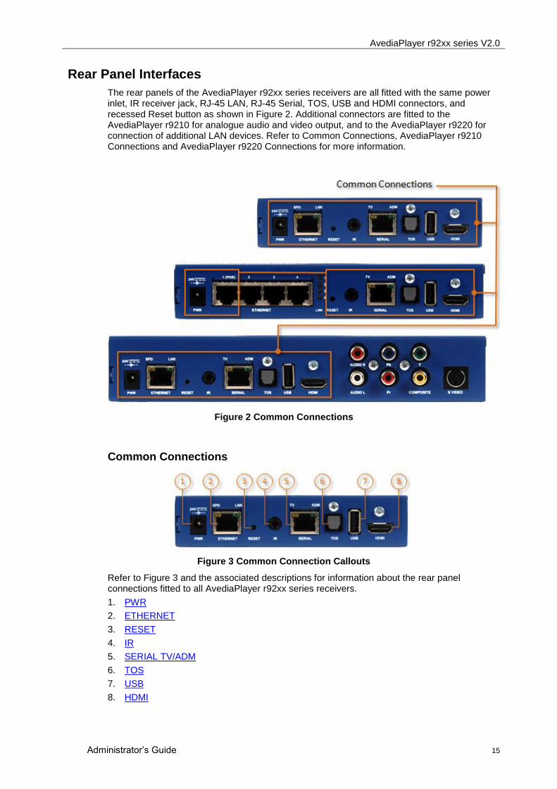
The rear panels of the AvediaPlayer r92xx series receivers are all fitted with the same power inlet, IR receiver jack, RJ-45 LAN, RJ-45 Serial, TOS, USB and HDMI connectors, and recessed Reset button as shown in Figure 2. Additional connectors are fitted to the AvediaPlayer r9210 for analogue audio and video output, and to the AvediaPlayer r9220 for connection of additional LAN devices. Refer to Common Connections, AvediaPlayer r9210 Connections and AvediaPlayer r9220 Connections for more information.
Figure 2 Common Connections
Common Connections
Figure 3 Common Connection Callouts
Refer to Figure 3 and the associated descriptions for information about the rear panel connections fitted to all AvediaPlayer r92xx series receivers.
1. PWR
2. ETHERNET
3. RESET
4. IR
5. SERIAL TV/ADM
6. TOS
7. USB
8. HDMI

AvediaPlayer r92xx series V2.0
16 Administrator‟s Guide
1. PWR
The receiver can be powered through the power jack using the 24V/3A external power adaptor available from Exterity as an accessory (avply-psu-##).
CAUTION: Do not use Idaptor (idapt-psXX) power supplies with the AvediaPlayer receivers.
2. ETHERNET
Ethernet (Ethernet 1 on AvediaPlayer r9220) is a 10/100 Mbps interface used to connect the receiver to the network switch using a standard straight-through Cat 5 cable.
On the AvediaPlayer r9200 and 9210 receivers two LEDs show the status of the Ethernet Interface. In normal operation the orange link LED is permanently lit if the connection is 100Mbps, not lit if it is 10Mbps. The green activity LED flickers on reception or transmission of packets.
On the AvediaPlayer r9220 Ethernet 1 should be used to connect the receiver to the network switch using a standard straight-through Cat 5 cable. The green activity LED (for port 1) flickers on reception or transmission of packets.
All AvediaPlayer r92xx series receivers are PoE enabled devices. They can be powered using any LAN Switch or Mid-span device meeting the 802.3af PoE specifications.
3. RESET
You can reset the receiver by pressing a pin or the end of a pen into the RESET port. You can also reset the receiver to the factory default settings.
Briefly press RESET to reboot the AvediaPlayer receiver.
Press and hold RESET until both ADM and TV LEDs flash to reset the device to factory default settings. (The serial port is set to admin control mode)
Note: Prior to version 2.0, the Admin/Serial port function was controlled using the RESET button. This is now configured on the TV Control page of the Web User Interface. Refer to Configuring TV Control on page 61.
4. IR
Connect the IR extender cable or tethered remote control to the IR jack to enable the user to control the receiver using the remote control handset when the front panel IR receiver window is obscured.
5. SERIAL TV /ADM
This RJ45 interface is dual purpose. Its function is configured on the TV page of the web interface. In its default configuration it can be used to access the command line admin interface to configure basic device capabilities and to troubleshoot problems. For details on using this interface, refer to Admin Interface on page 65 and APPENDIX C: Admin interface connection.
It can also be used to allow the receiver to communicate with a serial-controllable television. The interface wiring is shown in APPENDIX D. Contact your Exterity supplier for more details on supported televisions. Refer to Configuring TV Control on page 61 for more information.
6. TOS
Use a standard TOSLINK cable to connect the 2 channel PCM or Bitstream audio output to an external audio system if required.
7. USB
An external storage device (FAT32 format) can be connected to the USB port. The storage device can be used as a source of content and playlist to provide failover support.

AvediaPlayer r92xx series V2.0
Administrator‟s Guide 17
8. HDMI
Use a standard HDMI cable to connect the AvediaPlayer to an HD television/display.
Note: You must use HDMI compliant cables to connect the AvediaPlayer receiver to the display device
AvediaPlayer r9210 Connections
In addition to the common connections, the AvediaPlayer r9210 provides the connections shown in Figure 4. Common Connections on page 15 describes the connectors fitted to all AvediaPlayer r92xx receivers.
Figure 4 AvediaPlayer r9210 Connectors
1. Analogue Audio
Use standard phono cables to connect left/right analogue audio outputs (1 volt peak-to-peak maximum) to the similar-marked inputs on the television/display (not required if using HDMI).
2. Component /RGB/Composite Video
Use standard phono cables to output video to televisions/displays as follows:
Component Video (HD and SD): Connect the Y, Pb and Pr labelled outputs to the similar-marked inputs on the television.
Composite Video (SD only): Connect the Composite labelled output to the Composite input on the television.
Note: Only the HDMI interface is active when the AvediaPlayer receiver is decoding encrypted
content.
3. S-Video Interface
Use a standard S-Video cable to connect this interface to the S-Video input on the television (SD only).
AvediaPlayer r92xx series V2.0
18 Administrator‟s Guide
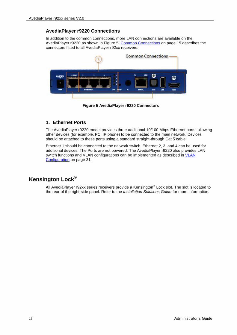
AvediaPlayer r9220 Connections
In addition to the common connections, more LAN connections are available on the AvediaPlayer r9220 as shown in Figure 5. Common Connections on page 15 describes the connectors fitted to all AvediaPlayer r92xx receivers.
Figure 5 AvediaPlayer r9220 Connectors
1. Ethernet Ports
The AvediaPlayer r9220 model provides three additional 10/100 Mbps Ethernet ports, allowing other devices (for example, PC, IP phone) to be connected to the main network. Devices should be attached to these ports using a standard straight-through Cat 5 cable.
Ethernet 1 should be connected to the network switch. Ethernet 2, 3, and 4 can be used for additional devices. The Ports are not powered. The AvediaPlayer r9220 also provides LAN switch functions and VLAN configurations can be implemented as described in VLAN Configuration on page 31.
Kensington Lock®
All AvediaPlayer r92xx series receivers provide a Kensington® Lock slot. The slot is located to
the rear of the right-side panel. Refer to the Installation Solutions Guide for more information.

AvediaPlayer r92xx series V2.0
Administrator‟s Guide 19
5 Remote Control
The AvediaPlayer r92xx series receivers can be controlled using the Exterity Infra Red (IR) or wired remote controllers.
This chapter contains the following sections:
Remote Control Key Functions
Inserting Batteries
Viewing Channels
Standby
Audio Language Selection
Using the Web Browser
Controlling Remote AV Devices
Remote Control Key Functions
The receiver remote controls are shown in Figure 6 and Figure 7.
Figure 6 IR and Wired Remote Control Functions

AvediaPlayer r92xx series V2.0
20 Administrator‟s Guide
Back/Cancel
Channel up
Channel down
Navigate left
Volume up
Volume down
Used with Portal and EPG
Used with Portal and EPG
Rewind
Play
Previous scene
Skip scene
Mode
View TV
Menu
Standby
Navigate up
Navigate right
Navigate Down
Mute
Used with Portal and EPG
Used with Portal and EPG
Fast forward
Pause
Record
Stop
View EPG
Open Browser/View home page
Figure 7 IR and Wired Remote Control Functions
Inserting Batteries
The batteries for the IR Remote Control are shipped separately. If the batteries in the remote control become exhausted, they should be replaced with two AAA sized replacements. Ideally use carbon zinc (R03) replacement batteries. Alkaline (LR03) batteries may be used but offer no advantage. Do not mix batteries of different types or age.
Caution: Do not fit batteries to the wired remote control.
WARNING: "Ultra" or "plus" batteries, especially those containing lithium (FR03), must not be
installed in the IR Remote Control.
To insert new AAA disposable batteries:
1. On the back of the IR Remote Control, pull the tab down on the battery compartment lid to detach it from the controller.
2. Insert two new AAA (R03 or LR03) batteries. Orient the batteries so that the positive (+) and negative (–) ends are positioned as shown by the diagram on the bottom of the battery compartment.
3. Relocate the battery compartment lid and push in to close.
AvediaPlayer r92xx series V2.0
Administrator‟s Guide 21
Viewing Channels
The channels list is built at start-up by listening to Session Announcement Protocol (SAP) announcements from head-end devices. This is an ongoing process and channels are added to and removed from the list as devices are reconfigured.
You can view and select channels using the receiver remote control:
To view television channels, use the TV button.
To display the list of channels, use the MENU button.
To navigate the list of channels, use the ▲/▼ buttons.
To select a channel, use the OK button.
To select a numbered channel directly, enter its number.
To change up or down between channels, use the CH- and CH+ buttons
To adjust the volume, use the VOL- and VOL+ buttons.
To mute the sound, use the MUTE button.
To pause, rewind or fast-forward an onDemand stream, use the PAUSE, REWIND or FAST
FORWARD buttons respectively.
To resume normal playback of an onDemand stream, use the PLAY button.
Standby
The receiver can be put into standby by pressing the STANDBY button on the remote control. This will turn off all audio/video outputs to the television or display. A subsequent press of the STANDBY button will turn the audio/video outputs back on and the last viewed channel will resume playing (unless an alternative start-up mode has been specified; see the Display section of this manual).
Audio Language and Subtitle Selection
Some TV channels have multiple audio streams in different languages. The audio language can be selected using the remote control as follows:
1. Display the Mode menu using the MODE button on the receiver remote control.
2. Select Audio Track using the ▲/▼ buttons and use the ◄/► buttons to choose the desired language.
3. Select Subtitles using the ▲/▼ buttons and use the ◄/► buttons to turn subtitles on or off. When enabled, select Subtitle Track using the ▲/▼ buttons and use the ◄/► buttons to choose the desired language.
4. Press MODE again to hide the menu.
Using the Web Browser
If configured, you can use the ANT Galio browser to view browser content on your television or display. You can control how pages are displayed using the web management interface, as described later in this manual. For example, you can define a home page to display when the browser opens, and you can specify whether pages display with a menu bar.
You can control the browser using the receiver remote control as follows:
To open a browser window, press the HOME button. To return to the home page, press the HOME button.
To navigate between links (if available), use the ▲/▼ buttons.
To select a link, press the SELECT button.

AvediaPlayer r92xx series V2.0
22 Administrator‟s Guide
Controlling Remote AV Devices
The receiver can send remote control button commands across a network to Exterity Encoders, where they are subsequently sent on to the attached AV device.
This capability is illustrated in Figure 8, where for example, the remote control handset could be used to play/pause/stop the DVD player.
Note: The remote control configuration file for the remote device must be present on the Encoder. Also, the Encoder must be properly configured as described in the Encoder Administrator’s Guide.
Figure 8 - Controlling remote AV devices
To control remote AV devices:
1. This feature is disabled by default. To enable it, enable Remote Device control as described in Configuring Remote Functions on page 63.
2. Display the Mode menu using the MODE button on the receiver remote control.
3. Select IR Controls using the ▲/▼ buttons and change the setting to AV Source.
4. If the remote device allows this functionality, text appears on screen to indicate the new mode.
5. Press MODE again to hide the menu.
You are now using Remote Device mode. All button commands (except MODE) are sent across the network to the remote device.
To return to normal operation:
1. Display the Mode menu using the MODE button on the remote control.
2. Select Normal in the IR Controls box.

AvediaPlayer r92xx series V2.0
Administrator‟s Guide 23
6 Management Interfaces
The receiver has 2 management interfaces: a web management interface accessible through a browser and the command line admin interface. In addition, the AvediaServer Director provides a subset of device controls. They can be accessed as follows:
AvediaServer Director
Web Management Interface
Terminal
Note: You can also use a third-party SNMP tool to manage the receiver. Contact your reseller to obtain the Management Information Base (MIB).
AvediaServer Director
The AvediaServer Director, as shown in Figure 9, is an application used for device discovery and management and is an integral part of the AvediaServer platform from version 3.2.0 onwards. The AvediaServer Director uses SNMP to manage a subset of device functionality and can also be used to start the AvediaPlayer web interface.
Figure 9 AvediaServer Director
The AvediaServer Director has the following capabilities:
Name - specify the AvediaPlayer name
Location – specify the AvediaPlayer location
Reboot – re-start the AvediaPlayer
Ping – Ping the AvediaPlayer
Upgrade Firmware – Upload new device firmware
Factory Reset – set the AvediaPlayer back to factory default configuration
Export Config – export the current configuration for archiving or applying to another device
Import Config – restore the AvediaPlayer to a previously saved configuration
Set TFTP Server – specify the IP address of the TFTP server to be used
Set Syslog Server – specify the IP address of the Syslog server to be used
Display Mode – set the display mode of the AvediaPlayer
Set Channel – set the AvediaPlayer to a specified channel
Homepage – specifies the homepage URL
AvediaPlayer r92xx series V2.0
24 Administrator‟s Guide
Groups – specifies the AvediaPlayer channel group memberships
Splash Screen – specifies the splash screen filename
Volume – set the AvediaPlayer output audio volume setting
To start the AvediaPlayer web interface with AvediaServer Director:
1. Open the AvediaServer web interface and click Director > Receivers to list all receivers in the IPTV system.
2. Use the column sort functions to help locate the receiver you want to configure.
3. Click the required AvediaPlayer name hyperlink to launch the AvediaPlayer web interface login window as shown in Figure 10.
4. Enter the admin login credentials to display the AvediaPlayer web interface as shown in Figure 11.
Web Management Interface
You can manage every aspect of the receiver‟s functionality using its web management interface. You can access the web management interface using the AvediaServer Director as shown above, or if known, by directly entering the IP address of the AvediaPlayer receiver into your browser address field:
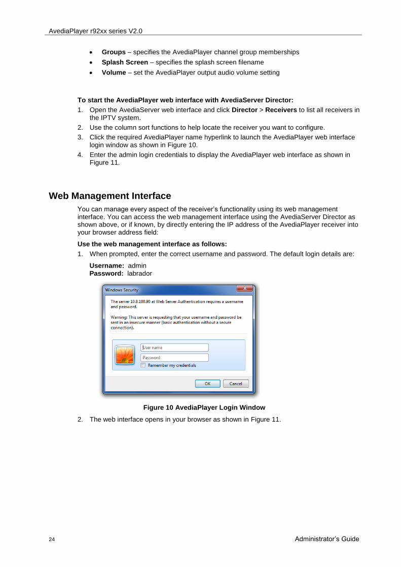
Use the web management interface as follows:
1. When prompted, enter the correct username and password. The default login details are:
Username: admin Password: labrador
Figure 10 AvediaPlayer Login Window
2. The web interface opens in your browser as shown in Figure 11.
AvediaPlayer r92xx series V2.0
Administrator‟s Guide 25
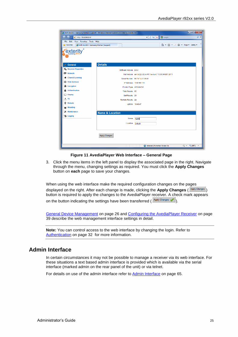
Figure 11 AvediaPlayer Web Interface – General Page
3. Click the menu items in the left panel to display the associated page in the right. Navigate through the menu, changing settings as required. You must click the Apply Changes button on each page to save your changes.
When using the web interface make the required configuration changes on the pages
displayed on the right. After each change is made, clicking the Apply Changes ( ) button is required to apply the changes to the AvediaPlayer receiver. A check mark appears
on the button indicating the settings have been transferred ( ).
General Device Management on page 26 and Configuring the AvediaPlayer Receiver on page 39 describe the web management interface settings in detail.
Note: You can control access to the web interface by changing the login. Refer to Authentication on page 32 for more information.
Admin Interface
In certain circumstances it may not be possible to manage a receiver via its web interface. For these situations a text based admin interface is provided which is available via the serial interface (marked admin on the rear panel of the unit) or via telnet.
For details on use of the admin interface refer to Admin Interface on page 65.
AvediaPlayer r92xx series V2.0
26 Administrator‟s Guide
7 General Device Management
The receiver is pre-configured to enable operation without need to use the management interface before connection to your IPTV network and TV.
For more detailed configuration information, refer to Configuring the AvediaPlayer Receiver on page 39.
Before reading this section, ensure that:
The receiver is powered on.
The receiver is attached to a multicast-enabled network.
The network containing your receiver has a DHCP server.
The infra-red receiver is visible or a remote „eye‟ is connected.
The receiver is connected to a television or display.
This chapter contains the following sections:
AvediaPlayer Receiver start-up
Engineering Screen
Naming the AvediaPlayer Receiver
Network Configuration
VLAN Configuration (AvediaPlayer r9220 only)
Authentication and Management
Configuring Web Services
Maintenance
Logging
AvediaPlayer Receiver start-up
The receiver start-up process consists of two stages:
Assigning an IP address to the receiver
Connecting to a channel (if receiver in Audio/Video mode)
When you switch the receiver on, a splash screen is displayed on the television or display, and the receiver attempts to obtain an IP address. The following message appears:
Configuring network interface
The receiver‟s LED flashes 4 times per second while waiting for a network link and carrying out the DHCP transactions.
Note: By default, the receiver requires a DHCP server to be available on the network to assign it an IP address. Once an IP address is assigned to the receiver, you can configure a static IP address using the management interface. A static IP address allows the receiver to operate without a DHCP server.
When an IP address has been allocated to the receiver, the LED enters its default status as described in Status LED on page 14.
AvediaPlayer r92xx series V2.0
Administrator‟s Guide 27
The receiver is set to Audio/Video mode by default, therefore the first time it starts up, it tries to find and connect to a channel. One of the following messages is displayed temporarily until a channel is found:
No channels available
This channel is not available
The channels list is collected automatically using announcements from head-end devices. This process requires approximately 1 minute.
On subsequent start-ups the receiver attempts to reconnect to the channel it was connected to previously.
Engineering Screen
The engineering screen displays information about the device including its name, IP address and firmware version. This may help you identify individual devices.
To display the engineering screen, press MODE and then PLAY on the remote control handset. To remove the engineering screen, press PLAY to return to the Mode menu, or press MODE to hide the menu completely.
AvediaPlayer r92xx series V2.0
28 Administrator‟s Guide
Naming the AvediaPlayer Receiver
You can specify a name and location for the AvediaPlayer receiver. This can be useful where a number of AvediaPlayers are installed, allowing you to uniquely identify each device. The name specified is also used to identify the device on a management station such as the AvediaServer Director.
You can use the web management interface or the AvediaServer Director to specify a name and location. (For more information refer to the AvediaServer Director Administrator‟s Guide.)
The following procedures use the AvediaPlayer web interface as described in Chapter 6 Management Interfaces.
A representative name and location can help you identify and manage more than one AvediaPlayer receiver. For example, when multiple receivers are deployed in a hospitality installation, you can use the room number and floor as the name and location. Exterity strongly recommends you configure meaningful <name> and <location> parameters where multiple AvediaPlayer receivers are deployed to aid and simplify system installation and ongoing management.
To specify a name for the device:
1. Click General to display the general page as shown in Figure 11.
2. Enter the name into the Name field.
3. Click the Apply Changes button.
To specify a location for the device:
1. Click General to display the general page as shown in Figure 11.
2. Type the name of a location into the Location field.
3. Click the Apply Changes button.
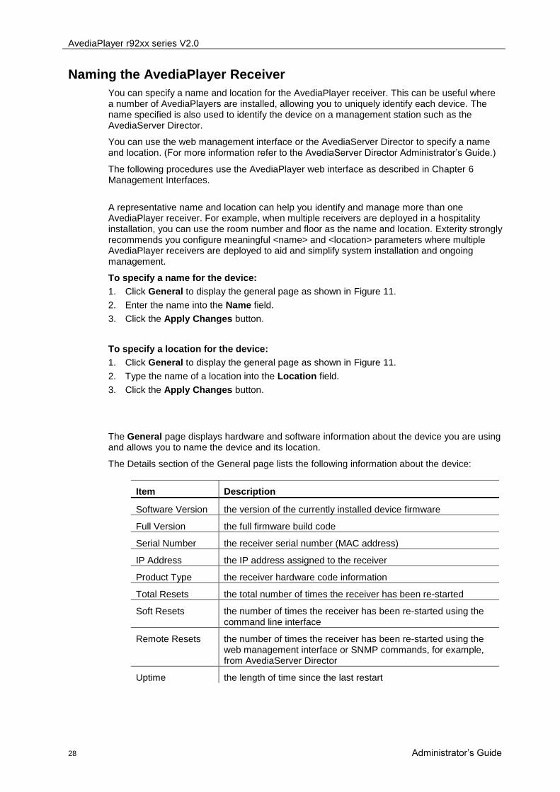
The General page displays hardware and software information about the device you are using and allows you to name the device and its location.
The Details section of the General page lists the following information about the device:
Item Description
Software Version the version of the currently installed device firmware
Full Version the full firmware build code
Serial Number the receiver serial number (MAC address)
IP Address the IP address assigned to the receiver
Product Type the receiver hardware code information
Total Resets the total number of times the receiver has been re-started
Soft Resets the number of times the receiver has been re-started using the command line interface
Remote Resets the number of times the receiver has been re-started using the web management interface or SNMP commands, for example, from AvediaServer Director
Uptime the length of time since the last restart

AvediaPlayer r92xx series V2.0
Administrator‟s Guide 29
Network Configuration
This section describes the configurations required to ensure the AvediaPlayer receiver connects to your IP network and interacts correctly with all other network devices. Additional switch settings are required to configure the AvediaPlayer r9220 four-port Ethernet switch.
Figure 12 Network Page (r9200 - Static IP address)
This section contains the following:
Network
Ethernet Settings
Ethernet Stats
Network
You can configure the receiver to obtain an IP address automatically using DHCP, or you can specify static addressing information, such as IP address, subnet mask and default gateway.
Note: Changes to IP addressing do not take place until after the device has restarted.
To configure the receiver to be allocated an IP address automatically:
1. Click Network to display the Network page as shown in Figure 12.
2. Click the IP Address Settings drop down list and select DHCP (Automatic).
3. Click the Apply Changes button.
Note: The settings in use are displayed greyed out.

AvediaPlayer r92xx series V2.0
30 Administrator‟s Guide
To configure a static receiver IP address:
1. Click Network to display the Network page as shown in Figure 12.
2. Click the IP Address Settings drop down list and select Static (Use below).
3. Specify values for IP Address, Subnet Mask, Default Gateway, Preferred DNS Server, and Alternate DNS Server.
4. Click the Apply Changes button.
Ethernet Settings
The receiver can automatically negotiate any combination of 10/100 Mbps and half/full duplex with an Ethernet switch (Auto setting). However, in certain situations it may be desired to limit the interface to 10Mbps with auto-negotiation enabled (Auto-10 setting), or to specify fixed speed/duplex settings with auto-negotiation disabled (100FD setting).
The default setting is 100Mbps full duplex with auto-negotiation (Auto).
The port Ethernet 0 is the uplink to the main network. On the AvediaPlayer r9220, ports Ethernet 1, 2 and 3 are ports to which additional network devices can be connected.
Note: It is important to make sure that the receiver settings match the settings on the switch port to which the receiver is connected, that is; if auto-negotiation is enabled on the receiver it must also be enabled at the switch. When a fixed setting has been configured on the receiver, the same fixed setting must be configured on the switch. Failure to do this may result in dropped packets which in turn may cause poor quality video output.
To specify Ethernet Settings:
1. Click Network to display the Network page as shown in Figure 12.
2. In the Switch Settings section, click the Ethernet 0 choose an option from the Mode dropdown box as required.
3. For the AvediaPlayer r9220, choose an option from the dropdown box for the appropriate interface. Valid options are Auto, Auto-10, 100FD.
4. Click Apply.
Ethernet Stats
Viewing the network port utilisation is an easy way to check if the AvediaPlayer receiver is receiving data at the rate expected for the current configuration. For example, displaying the browser homepage requires little traffic, whereas playing an HD channel results in a large amount of Receive traffic.
To view network port utilisation:
1. Click Network to display the Network page as shown in Figure 12.
2. Locate and observe the Ethernet Stats section at the end of the Network page.

AvediaPlayer r92xx series V2.0
Administrator‟s Guide 31
VLAN Configuration (AvediaPlayer r9220 only)
This section describes setting up 802.1q VLANs on the AvediaPlayer r9220 receiver internal switch.
Note: The AvediaPlayer r9200 and r9210 do not support VLANs.
You can enable the use of 802.1q VLANs and set VLAN IDs for each port. Using VLANs allows you to ensure the IPTV system and other network traffic, for example VOIP phone and computer systems, are segregated. The VLAN page is shown in Figure 13.
Figure 13 VLAN Settings
Port Ethernet 1 must be the uplink to the main network, and is configured as a VLAN trunk port. This means that all packets transmitted tagged on this port, with the exception of packets on the configured Native VLAN, which are transmitted untagged.
Ports Ethernet 2, Ethernet 3, and Ethernet 4 are the ports to which additional network devices can be attached. Outgoing traffic is transmitted untagged on these ports, while incoming traffic is tagged with the configured VLAN ID prior to transmission on the uplink.
The Host port is the switch port to which the actual receiver is attached, that is, the port on the switch which passes streaming and management traffic to the receiver. Like ports 1 and 2, outgoing traffic is transmitted untagged on this port, while incoming traffic is tagged with the configured VLAN ID.
To enable the use of VLANs:
1. Click VLAN to display the VLAN Settings page as shown in Figure 13.
2. Click the 802.1Q VLAN Support drop down list and select Enabled.
3. Enter the native VLAN ID in the Native VLAN field. This should match the Native (Default) VLAN ID of the main network.
4. Enter VLAN IDs for Ethernet 2, Ethernet 3, and Ethernet 4 as required.
5. Click the Apply Changes button.

AvediaPlayer r92xx series V2.0
32 Administrator‟s Guide
Authentication and Management
The Authentication and Web services pages allow you to:
configure Authentication to control access to the web management interface
enable SNMP control of the receiver and specify the SNMP trap manager address
specify the browser homepage URL
specify the program guide (EPG) server address
enable connection through a proxy and specify the address
The Web Services page contains 4 sections: Browser, EPG, and Proxy Settings, you to configure the address of the browser homepage, the address of EPG server, and the use of a web proxy server.
Figure 14 Authentication Page
Authentication
You can ensure access to the AvediaPlayer web interface is restricted by the use of a password (default setting).
To restrict access by password:
1. Click Authentication to display the page as shown in Figure 14.
2. Click the Allow web access to drop down list to select Authenticated Users.
3. Enter the password you want to use in the Admin Password field.
4. Click the Apply Changes button.
To allow access to all users:
1. Click Authentication to display the page as shown in Figure 14.
2. Click the Allow web access to drop down list to select All Users.
3. Click the Apply Changes button.
SNMP Agent
SNMP is used to manage a subset of the AvediaPlayer receiver functions, such as reboot and return- to-factory default settings. The AvediaServer Director is an application which uses SNMP for device discovery and management. Director can also be used to locate an AvediaPlayer receiver and start its web management interface.
With SNMP disabled, a warning symbol is displayed in the Name cell of the receiver listing in the Director to indicate it cannot respond to Director Actions. Disable SNMP control only if

AvediaPlayer r92xx series V2.0
Administrator‟s Guide 33
the AvediaPlayer receiver management is to be constrained to the serial and web management interfaces only.
To enable SNMP device management:
1. Click Authentication to display the page as shown in Figure 14.
2. Click the Agent drop down list to select On.
3. Ensure the Community fields display public.
4. Click the Apply Changes button.
SNMP TrapSettings
SNMP traps are mainly used as device discovery messages; they enable Exterity‟s management applications to discover devices on the network. These traps are always broadcast to 255.255.255.255. They are also broadcast to the multicast address 239.255.255.255, but this can be reconfigured if desired
To set the SNMP trap manager address:
1. Click Web Services to display the page as shown in Figure 22.
1. Enter the required IP address in the SNMP Trap Manager field.
2. Click the Apply Changes button.
AvediaPlayer r92xx series V2.0
34 Administrator‟s Guide
Maintenance
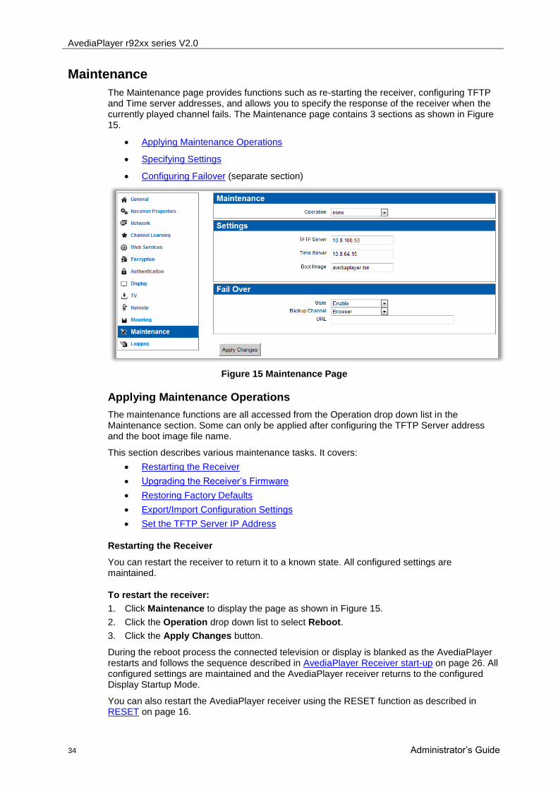
The Maintenance page provides functions such as re-starting the receiver, configuring TFTP and Time server addresses, and allows you to specify the response of the receiver when the currently played channel fails. The Maintenance page contains 3 sections as shown in Figure 15.
Applying Maintenance Operations
Specifying Settings
Configuring Failover (separate section)
Figure 15 Maintenance Page
Applying Maintenance Operations
The maintenance functions are all accessed from the Operation drop down list in the Maintenance section. Some can only be applied after configuring the TFTP Server address and the boot image file name.
This section describes various maintenance tasks. It covers:
Restarting the Receiver
Upgrading the Receiver‟s Firmware
Restoring Factory Defaults
Export/Import Configuration Settings
Set the TFTP Server IP Address
Restarting the Receiver
You can restart the receiver to return it to a known state. All configured settings are maintained.
To restart the receiver:
1. Click Maintenance to display the page as shown in Figure 15.
2. Click the Operation drop down list to select Reboot.
3. Click the Apply Changes button.
During the reboot process the connected television or display is blanked as the AvediaPlayer restarts and follows the sequence described in AvediaPlayer Receiver start-up on page 26. All configured settings are maintained and the AvediaPlayer receiver returns to the configured Display Startup Mode.
You can also restart the AvediaPlayer receiver using the RESET function as described in RESET on page 16.

AvediaPlayer r92xx series V2.0
Administrator‟s Guide 35
Upgrading the Receiver Firmware
By upgrading the receiver‟s firmware regularly, you can ensure that you are always using the most recent receiver software. As the new firmware is uploaded using TFTP, you must ensure that the receiver is using the correct TFTP server address.
Caution: Do not switch the receiver off while the upgrade process is running. The process
requires several minutes.
To upgrade the receiver to a new version of firmware:
1. Ensure you have specified the IP address of your TFTP server in the Settings section of the page.
2. Ensure the required firmware file is located in the root directory of the TFTP server, and the server is running.
3. Click Maintenance to display the page as shown in Figure 15.
4. Ensure that the required firmware file is hosted correctly in the root directory of the TFTP server, for example: AvediaPlayer_2_0_1.bin
5. In the Settings section, ensure that the Boot Image filename field matches the name of
the firmware file required; AvediaPlayer_2_0_1.bin in this example.
6. Click the Operation drop down list to select Upgrade Firmware.
7. Click the Apply Changes button.
Note: Ensure the correct firmware file is specified in the Boot Image field of the Settings
section.
Restoring Factory Defaults
You can return the AvediaPlayer receiver to its factory default configuration. You can restore the device to its factory defaults using the web management interface as described in the following procedure, or using the rear panel RESET function as described in RESET on page 16.
Note: If you restore the receiver to factory default settings, all previously saved settings are lost. IP addressing is also returned to DHCP. You can however restore these if you have previously saved your configuration, as described later in this section.
To restore the receiver factory default settings:
1. Click Maintenance to display the page as shown in Figure 15.
2. Click the Operation drop down list to select Return to Factory Defaults.
3. Click the Apply Changes button.
During the reboot process the connected television or display is blanked as the AvediaPlayer restarts and follows the sequence described in AvediaPlayer Receiver start-up on page26.
Export/Import Configuration Settings
Once you have configured the receiver, you can store your configuration settings in a single file. You can use the file to restore your settings should you need to. You can also use a saved configuration to replicate identical settings on multiple devices. You must ensure that the receiver is using the correct TFTP server address.
NOTE: Device naming and IP addressing information is not exported/imported. This allows a
configuration file to be imported and used on multiple units.
AvediaPlayer r92xx series V2.0
36 Administrator‟s Guide
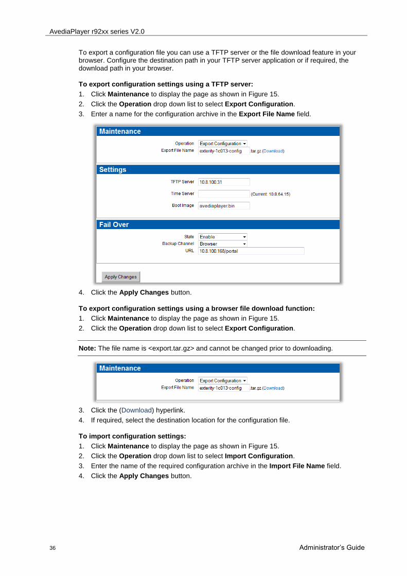
To export a configuration file you can use a TFTP server or the file download feature in your browser. Configure the destination path in your TFTP server application or if required, the download path in your browser.
To export configuration settings using a TFTP server:
1. Click Maintenance to display the page as shown in Figure 15.
2. Click the Operation drop down list to select Export Configuration.
3. Enter a name for the configuration archive in the Export File Name field.
4. Click the Apply Changes button.
To export configuration settings using a browser file download function:
1. Click Maintenance to display the page as shown in Figure 15.
2. Click the Operation drop down list to select Export Configuration.
Note: The file name is <export.tar.gz> and cannot be changed prior to downloading.
3. Click the (Download) hyperlink.
4. If required, select the destination location for the configuration file.
To import configuration settings:
1. Click Maintenance to display the page as shown in Figure 15.
2. Click the Operation drop down list to select Import Configuration.
3. Enter the name of the required configuration archive in the Import File Name field.
4. Click the Apply Changes button.

AvediaPlayer r92xx series V2.0
Administrator‟s Guide 37
TFTP Server IP Address
The receiver uses TFTP to download new firmware releases, remote control configuration files and splash screens. For this to operate correctly, the receiver must be configured to communicate with the TFTP server.
To specify a TFTP server IP address:
1. Click Maintenance to display the page as shown in Figure 15.
2. Enter the IP address of the TFTP server in the TFTP Server field.
3. Click the Apply Changes button.
Time Server
Use of a Time Server with the Time Zone configuration ensures all devices in your IPTV system are synchronised to the current local time in use. The receiver uses NTP to maintain accurate time on the device, using the time server specified. This is also useful when examining the device log files as each log message has an accurate universal time code (UTC) timestamp. (The local time zone is configured in the Miscellaneous section of the Receiver Properties page.)
Note: When DHCP is used and the DHCP server supplies an NTP server address, any NTP servers configured using the Web Management Interface are ignored. If the DHCP server does not supply an NTP server address, the address must be configured.
To configure a Time Server:
1. Click Receiver Properties to display the page as shown in Figure 19.
2. Enter the IP address or host name of the server you want to use in the Time Server field. If already configured, the IP address is displayed.
3. Click the Apply Changes button.
Boot Image
You can specify the name of the file you want to use when uploading and installing receiver firmware. This allows you to manage firmware for multiple receiver models and versions by including relevant information in the name of the firmware files held on your server. Specify the required file when performing the upgrade. View the upgrade procedure in Upgrading the Receiver Firmware.

AvediaPlayer r92xx series V2.0
38 Administrator‟s Guide
Logging
You can compile and store files that provide receiver logging information. These files can be used to view historical information about receiver activity.
To save device log information to a remote server, you need to specify a syslog server.
The log file can also be viewed using the management interface without the need for a syslog server.
Figure 16 Logging Page - Local and Remote Selected
To configure remote logging:
1. Click Logging to display the page as shown in Figure 16.
2. Click the Logging drop down list and select Local and Remote.
3. In the Syslog Server entry fields, enter the IP address or host name and the port number of the syslog server where the log files are to be stored. The default port number is 514.
4. Click the Remote logging level drop down list and select a logging level option ranging from 0-Emergency to 7-Debug, where 0 represents the least debug information and 7 represents the most.
5. Click the Apply Changes button.
To view the locally saved log file:
1. Click Logging to display the page as shown in Figure 16.
2. Click the View Log hyperlink adjacent to the Logging drop down list to display the log in a new browser window as shown in Figure 17.
Figure 17 Log File

AvediaPlayer r92xx series V2.0
Administrator‟s Guide 39
8 Configuring the AvediaPlayer Receiver
This chapter describes the configuration of the AvediaPlayer r92xx series using the web interface as shown in Figure 18.
Figure 18 Web Interface - General Page
The web interface allows configuration of all aspects of the AvediaPlayer receivers. The configuration pages are displayed in the right hand pane and are accessed by clicking a menu item in the left hand pane. This chapter describes each of the following menu pages:
Basic Settings
Configuring Channel Learning
Displaying Content
Handling Encrypted Content
Using External Storage Devices
Configuring Failover
Configuring TV Control
Configuring Remote Functions
Make the required configuration changes on the pages displayed on the right. After each
change is made, clicking the Apply Changes ( ) button is required to apply the changes to the AvediaPlayer receiver. A check mark appears on the button indicating the
settings have been transferred ( ).
AvediaPlayer r92xx series V2.0
40 Administrator‟s Guide
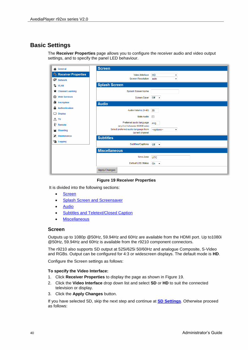
Basic Settings
The Receiver Properties page allows you to configure the receiver audio and video output settings, and to specify the panel LED behaviour.
Figure 19 Receiver Properties
It is divided into the following sections:
Screen
Splash Screen and Screensaver
Audio
Subtitles and Teletext/Closed Caption
Miscellaneous
Screen
Outputs up to 1080p @50Hz, 59.94Hz and 60Hz are available from the HDMI port. Up to1080i @50Hz, 59.94Hz and 60Hz is available from the r9210 component connectors.
The r9210 also supports SD output at 525i/625i 50/60Hz and analogue Composite, S-Video and RGBs. Output can be configured for 4:3 or widescreen displays. The default mode is HD.
Configure the Screen settings as follows:
To specify the Video Interface:
1. Click Receiver Properties to display the page as shown in Figure 19.
2. Click the Video Interface drop down list and select SD or HD to suit the connected television or display.
3. Click the Apply Changes button.
If you have selected SD, skip the next step and continue at SD Settings. Otherwise proceed as follows:

AvediaPlayer r92xx series V2.0
Administrator‟s Guide 41
To specify the Screen Resolution:
1. Click Receiver Properties to display the page as shown in Figure 19.
2. Click the Screen Resolution drop down list and select 480p 60Hz, 576p 50Hz, 720p 60Hz, 720p 50Hz, 1080i 60Hz, 1080i 50Hz, 1080p 60Hz, 1080p 50Hz, or auto to suit the connected television or display. You should use auto unless you want to use a specific resolution and frame rate.
3. Click the Apply Changes button.
Note: In HD mode the r9210 outputs to both HDMI and Component connections at settings up to 1080i. If a setting of 1080p manually set or is negotiated when set to auto, only the HDMI output is available. Analogue audio is available at all times from the phono connectors (at 1 volt peak-to-peak maximum).
SD Settings
If you selected SD you can specify whether the receiver is connected to a Normal (4:3) or Widescreen (16:9) television or display. When in SD mode and connected to a Normal (4:3) television or display, the Aspect Ratio setting controls how a widescreen signal is displayed. There are two options:
Centre – Displays the centre of the widescreen image. The left and right outside margins of the picture are lost.
Letterbox – Displays the complete widescreen image with black bars at top and bottom.
The settings are not relevant in HD mode.
To set the Screen Format and Aspect Ratio:
1. Click Receiver Properties to display the page as shown in Figure 19.
2. Click the Screen Format drop down list and select Normal or Widescreen.
3. If you selected Normal, click the Aspect Ratio drop down list and select Letter Box or Center.
4. Click the Apply Changes button.
Splash Screen and Screen Saver
You can specify an image to be displayed as a splash screen when the receiver is turned on. The splash screen is also displayed if the receiver fails to connect to a stream or when an audio-only channel is being played. The image is downloaded from a TFTP server and can be
.jpg, .gif or .png file format.
When creating a splash screen image for HD output, restrict the image to a resolution of 1280x720 pixels and a maximum of 32-bit colour quality. A splash screen for SD output should have maximum size 720x576 pixels and 32-bit colour quality. The maximum file size is 1MB.
You can specify the length of time the splash screen or a static icon is displayed before the screen is blanked or the icon removed. For example, if a radio channel is being played and the splash screen displayed, the screen can be blanked after a specified wait period. Similarly, an icon such as „mute‟ is removed after the specified wait even if motion video is being played.
AvediaPlayer r92xx series V2.0
42 Administrator‟s Guide
To specify the Splash Screen image:
1. The receiver uses TFTP to download new splash screen images from a TFTP server. To update the splash screen, first ensure that the correct TFTP server IP address is specified in the Maintenance page Settings section, and that the TFTP server is running.
2. Click Receiver Properties to display the page as shown in Figure 19.
3. Enter the name of the image file, including the file extension, into the Splash Screen Name field.
4. Click the Apply Changes button.
The splash screen file is now downloaded from the TFTP server.
To turn the Screen Saver on:
1. Click Receiver Properties to display the page as shown in Figure 19.
2. Click the Screen Saver drop down list and select On.
3. Enter the required delay in the Wait (Mins) field.
4. Click the Apply Changes button.
Audio
You can set the level of audio volume output from the receiver. This is a value between 0 (min volume) and 40 (max volume). The default is 20. You can also turn off the audio output using the Mute Audio function. Audio is enabled by default. Some TV channels have multiple audio streams in different languages. The receiver can be configured with a preferred audio language. If a channel contains an audio stream of this language it is selected, otherwise the first language found is used.
To set the Audio Volume:
1. Click Receiver Properties to display the page as shown in Figure 19.
2. Enter a value between 0 and 40 in the Audio Volume field.
3. Click the Apply Changes button.
To mute the audio output:
1. Click Receiver Properties to display the page as shown in Figure 19.
2. Click the Mute Audio checkbox to display .
3. Click the Apply Changes button.
To set the preferred audio language:
1. Click Receiver Properties to display the page as shown in Figure 19.
2. In the Preferred audio language field, enter the two or three character ISO639 code for the language, or if the current channel has embedded language codes you can click the Select preferred audio language from current channel drop down list and select the language you want to use.
3. Click the Apply Changes button.
The audio language can also be selected using the remote control as follows:
1. Display the Mode menu on the television or display using the MODE button on the receiver remote control.
2. Select Audio Track using the ▲/▼ buttons and use the ◄/► buttons to choose the desired option.
3. Press MODE again to hide the menu.

AvediaPlayer r92xx series V2.0
Administrator‟s Guide 43
Configure Subtitles/Closed Captions and Teletext
Subtitles/Closed Captions and Teletext on VBI (vertical blanking interval) can be displayed in a selected language when available. For each, the default setting is off.
Teletext is available only on the composite output of the AvediaPlayer r9210 receiver. Connect to the TV composite input and press TEXT on the TV remote control to view and select the teletext pages.
To display subtitles:
1. Click Receiver Properties to display the page as shown in Figure 19.
2. Click the Subtitles/Captions drop down list to select On.
3. In the Preferred subtitle language field, enter the two or three character ISO639 code for the language, or; if the current channel has embedded language codes you can click the Select preferred
subtitle language from current channel drop down list and select the language you want to use.
4. Click the Apply Changes button.
To display closed captions:
1. Click Receiver Properties to display the page as shown in Figure 19.
2. Click the Subtitles/Captions drop down list to select On.
3. Click the Close caption channel drop down list to select the required CC channel (CC1 to CC4).
4. Click the Apply Changes button.

AvediaPlayer r92xx series V2.0
44 Administrator‟s Guide
To enable teletext:
1. Click Receiver Properties to display the page as shown in Figure 19.
2. Click the Enable Teletext on VBI drop down list to select On.
3. Click the Apply Changes button.
Note: Enabling Teletext disables SD component video output on the AvediaPlayer r9210.
Miscellaneous
The Miscellaneous section allows you to configure the Time Zone and the operation of the front panel LED. (The Time Server is configured on the Maintenance section on page 33.)
Time Zone
Use of a Time Server with the Time Zone configuration ensures all devices in your IPTV system are synchronised to the current local time in use. The receiver uses NTP to maintain accurate time on the device, using the time server specified. This is also useful when examining the device log files as each log message has an accurate universal time code (UTC) timestamp.
LED Behaviour
The main LED on the front of the receiver can be configured to have default mode On or Off .If default status is On, the LED pulses constantly, blinking in response to input from the remote control handset. If default status is Off, the LED stays off constantly, blinking in response to input from the remote control handset. The default value for this setting is On, pulsing.
To configure the Time Zone:
1. Click Receiver Properties to display the page as shown in Figure 20.
2. Enter the local time zone in the Time Zone field.
3. Click the Apply Changes button.
To set the default LED status:
1. Click Receiver Properties to display the page as shown in Figure 19.
2. Click the Default LED Status drop down menu and select On or Off.
3. Click the Apply Changes button.

AvediaPlayer r92xx series V2.0
Administrator‟s Guide 45
Configuring Channel Learning
This section shows you how to configure the AvediaPlayer receiver to find and display channel information and how to assign group membership. The receiver can use two mechanisms to build the list of channels: SAP (default) and XML.
When SAP is selected, the channel list is built up from SAP (Session Announcement Protocol) announcements generated by Exterity Encoders, TV Gateways and other compatible products.
When XML is selected, the channel list is created from the listing in an XML file downloaded by the receiver from a web server. To ensure the list is up to date, you can configure the receiver to download the file at specified intervals.
The channel list function can also be switched off entirely.
Figure 20 Channel Learning Page
Static Channels
The AvediaPlayer r92xx series receivers also support the use of Static Channels. These can be channels where you want to:
include some files held on local/remote storage devices and include them in the channel listing
include content from a source that does not use SAP to announce the presence of the channel
add a channel but hide its listing from the Program Guide
For more information about the tools and processes required to configure Static Channels refer to the Exterity Knowledge Base article KB000295.
Select SAP
By default, the AvediaPlayer receiver listens for these announcements on the multicast address 239.255.255.255. If there are devices on the network sending announcements to another IP address, you can configure the receiver to listen for these announcements by adding the IP address to the SAP Announcement Multicast Address table. For example to receive announcements from the Cisco IPTV solution, configure the receiver to listen on multicast address 224.2.127.254.

AvediaPlayer r92xx series V2.0
46 Administrator‟s Guide
To set an additional multicast address:
1. Click Channel Learning to display the Channel Learning page as shown in Figure 20.
2. Click the Channel Learning Type drop down list to select SAP.
3. Enter the new IP address into the (New Address) field.
4. Click the adjacent checkbox.
5. Repeat this process to add multicast addresses as required.
6. Enable or disable the listed addresses using the adjacent checkboxes.
7. Click the Apply Changes button.
Specifying Group Membership
The available channels across a network of Exterity devices can be split into groups of similar type. For example, you might have a group of Sports channels and a group of Children‟s channels. Channels are assigned to group(s) by Exterity Encoders and TV Gateways. The groups are included as part of the SAP announcements sent by these devices.
If you do not configure any groups on a receiver (i.e. receiver is in the “all” group), then all channels are available from the channels menu on that receiver. Configuring one or more groups on a receiver means that only channels in those groups are displayed in the channels list. Assigning receivers to a Group(s) where the channels are appropriate for the user of the receiver ensures content is restricted as intended.
Figure 21 Groups Page

AvediaPlayer r92xx series V2.0
Administrator‟s Guide 47
To add the receiver to a channel group:
1. Click Channel Learning to display the page as shown in .
2. In the Groups panel, select a previously configured group by clicking the associated checkbox or,
3. Enter a new group name in the New Group field and click the adjacent checkbox.
4. Click the Apply Changes button.
Select XML Channel List
In XML mode, the channel list is an XML file which the receiver downloads from a web server. To ensure the list is up to date, the receiver downloads the file at an interval specified by the administrator.
The format of the channel list is described in APPENDIX B.
To set the channel list URL:
1. Click Channel Learning to display the Channel Learning page as shown in Figure 20.
2. Click the Channel Learning Type drop down list to select XML.
3. Enter URL of the XML file into the Channel List URL field. (With DNS available on your network, you can use the form http://www.example.com/my_channel_list
4. Enter the interval in minutes into the Refresh Interval field.
5. Click the Apply Changes button.
Disable Channel Learning
You can disable Channel Learning if the AvediaPlayer receiver is to be used in a Portal only or digital signage application where there is no requirement for additional channels.
To disable channel learning:
1. Click Channel Learning to display the Channel Learning page as shown in Figure 20.
1. Click the Channel Learning Type drop down list to select None.
2. Click the Apply Changes button.

AvediaPlayer r92xx series V2.0
48 Administrator‟s Guide
Configuring Web Services
The Web Services page contains 4 sections: Browser, EPG, and Proxy Settings, enabling you to configure the address of the browser homepage, the address of EPG server, and the use of a web proxy server. Click Web Services to display the page as shown in Figure 22.
Figure 22 Web Services Page
Browser
The receiver includes the ANT Galio web browser. Use the options described in this section to control the web browsing feature. For example, you can define a home page that is displayed each time the browser is accessed and enable or disable the display of the browser toolbar. To use the AvediaServer portal and its functions, set the Homepage as follows:
http://<server IP address>/portal
To view the browser on a television or display, press the HOME button on the remote control.
To set a browser home page:
1. Click Web Services to display the page as shown in Figure 22.
2. Enter the URL of the web page you want to configure as the homepage location into the Homepage field. For example, Figure 22 shows the address of an AvediaServer portal page.
3. Click the Show Toolbar drop down list to select On or Off as required. When On, the ANT Galio toolbar is displayed at the top of the screen.
4. Click the Apply Changes button.
EPG
This section describes how to configure the receiver for interoperation with the Exterity AvediaServer EPG application. The Electronic Program Guide application provides a web page which the receiver can access. This is displayed on the connected television or display and allows the user to browse and select from the available programs. By default, the EPG is accessed using the GUIDE button on the remote control handset.
To configure the EPG server address:
1. Click Web Services to display the page as shown in Figure 22.
2. Enter the IP address of the EPG server into the EPG Server Address field.
3. Click the Apply Changes button.

AvediaPlayer r92xx series V2.0
Administrator‟s Guide 49
Proxy Settings
You can configure the receiver to use a direct connection to the internet or you can specify a proxy server to be used instead. If you use a proxy server for a general internet connection, but still want to use a direct connection for particular sites, you can specify exceptions. These sites can then be accessed by the browser without using the proxy server.
To use a direct connection to the internet:
1. Click Web Services to display the page as shown in Figure 22.
2. Click the Proxy Settings drop down list to select Direct Connection.
3. Click the Apply Changes button.
To use a proxy server:
1. Click Web Services to display the page as shown in Figure 22.
2. Click the Proxy Settings drop down list to select Manual Proxy.
3. Enter the IP address and port (address:port) of the proxy server into the Proxy Address fields.
4. In the Ignore Domains field, enter the address where a direct connection is to be used and click the check box. Repeat this process to add additional direct connection addresses as required. You can change a direct connection to a proxy connection by clicking the associated checkbox to remove the tick mark.
5. Click the Apply Changes button.

AvediaPlayer r92xx series V2.0
50 Administrator‟s Guide
Displaying Content
The Display page contains 3 sections which allow you to control what the receiver displays on the connected television or display.
Display enables configuration of the start up and current display mode. URLs allow you to specify a web page to be displayed when in browser mode, and you can select a channel from the Current Channel list to be played when in AV mode.
Click Display to open the page as shown in Figure 23. Any configuration changes made are applied immediately when you click the Change Channel or Apply Changes buttons.
For example, you can change the current channel or temporarily override the web page being displayed.
Figure 23 Display Page
Display
The Display section allows you to configure both the start up display mode for the AvediaPlayer receiver and the current mode.
Various display modes are defined as follows:
Off: turn off all audio/video outputs to the television or display (Not available as a start-up mode)
Audio/Video: plays selected TV and Radio channels (default)
Web Browser: runs the ANT Galio browser, displaying the web page specified in the Webpage field of the URLs section. If none is configured, the Homepage configured on the Web Services page is displayed. Refer to Browser on page 48 for more information.

AvediaPlayer r92xx series V2.0
Administrator‟s Guide 51
Splash Screen: displays the specified splash screen (configured on the Receiver Properties page – refer to Splash Screen and Screen Saver on page 41)
Playlist: plays back the files in the configured playlist
EPG: displays the program guide from the Exterity EPG server (configured on the Web Services page – refer to EPG on page 48.
Startup Mode
You can specify the startup mode for the AvediaPlayer receiver. The available options are: Audio/Video, Web Browser, Splash Screen, Playlist and EPG. The Default is Audio/Video.
To set the startup display mode:
1. Click Display to display the page as shown in Figure 23.
2. Click the Startup Mode drop down list to select Audio/Video, Web Browser, Splash Screen, Playlist or EPG.
3. Click the Apply Changes button.
Current Mode
You can control the current mode of operation. The available options are: Off, Audio/Video, Web Browser, Splash Screen, Playlist and EPG. The default is Audio/Video. You can use the current mode setting to override the current display.
To set the current display mode:
1. Click Display to display the page as shown in Figure 23.
2. In the Display section, click the Current Mode drop down list to select Off, Audio/Video, Web Browser, Splash Screen, Playlist or EPG.
3. Click the Apply Changes button.
4. The connected television or display is updated.
The user can regain control of the television or display using the remote control.
URLs
Webpage
While in browser mode, you can use the web management interface to navigate the browser to a particular page, overriding the home page.
To display a web page:
1. Click Display to display the page as shown in Figure 23.
2. In the URLs section, enter a URL into the Webpage field.
3. Select Web Browser from the Current Mode drop down list in the Display section.
4. Click the Apply Changes button to display the selected webpage on the connected television or display.
Note: This field is cleared after the changes are applied. Subsequent Web Browser Display Mode changes display the Homepage (if configured in the Browser section of the Web
Services page).
The user can regain control of the television or display using the remote control.

AvediaPlayer r92xx series V2.0
52 Administrator‟s Guide
Playlist
In playlist mode, the AvediaPlayer receiver plays the files specified in the playlist file. The playlist file can be hosted on a local (USB) memory stick or a web server. To configure the receiver to run a playlist, the URL of the playlist must be specified. For the format of the playlist file, refer to Appendix-B.
To select a playlist:
1. Click Display to display the page as shown in Figure 23.
2. In the URLs section, enter a URL into the Playlist field. (The example in Figure 24 shows the URL of a playlist in the mounted USB Memory stick)
3. Select Playlist from the Current Mode drop down list in the Display section.
Figure 24 Playlist in local USB memory stick
4. Click the Apply Changes button to play the specified playlist.
The user can regain control of the television or display using the remote control.
Current Channel
While in Audio/Video mode you can change the channel by selecting one from the channels in the list. You can order the listed channels by clicking on the Number, Name, URI or Group column headings. Clicking a heading again reverses the order.
You can also specify on-demand playback, a file located on a local or remote mounted storage device, or content from a web server.
To set the current channel in audio/video mode:
1. Click Display to display the page as shown in Figure 23.
2. In the Current Channel section you can:
If known, enter the URI of the channel in the URI field, or
Click on a suitable column heading to help locate the channel you want and click the associated radio button to select it.

AvediaPlayer r92xx series V2.0
Administrator‟s Guide 53
3. Click the Change Channel or Apply Changes button.
4. The selected channel is displayed on the connected television or display. The user can regain control of the channel selection using the remote control.
Source Specific Multicast (SSM) is supported by the AvediaPlayer r92xx receivers. SSM is an enhancement to IP multicast (defined in IGMP v3) and also requires support in your network switches. Using SSM, the receiver expresses interest in receiving traffic from only one specific source, thus reducing the amount of multicast routing information that must be maintained by the network.
If IGMP V3 is not implemented on your network, the r92xx receivers operate using IGMP v2.
Note: If you are specifying the URL of a channel, use the following format: <protocol>://<address>[:<port>][/<filename>]
Examples:
Multicast stream (UDP or RTP): udp://239.192.0.72:5000
Source Specific Multicast stream (UDP or RTP): udp://[email protected]:5000
onDemand playback (RTSP): rtsp://10.8.64.72:8554/football.mpg
local file: file:///mnt/sda1/samplemedia.ts
remote file: file:///mnt/media/samplemedia.ts
HTTP playback: http://10.8.90.99/video/backup.ts
To play a file on a mounted device example:
1. Ensure the device containing the file you want to play is correctly mounted as described in Using External Storage Devices on page 55.
2. Enter the file path name in the Current Channel entry field in the form: file://</mount point/filename>.
3. Click the Change Channel button to play the file.
Refer to Appendix A for more information about playlist content and syntax.
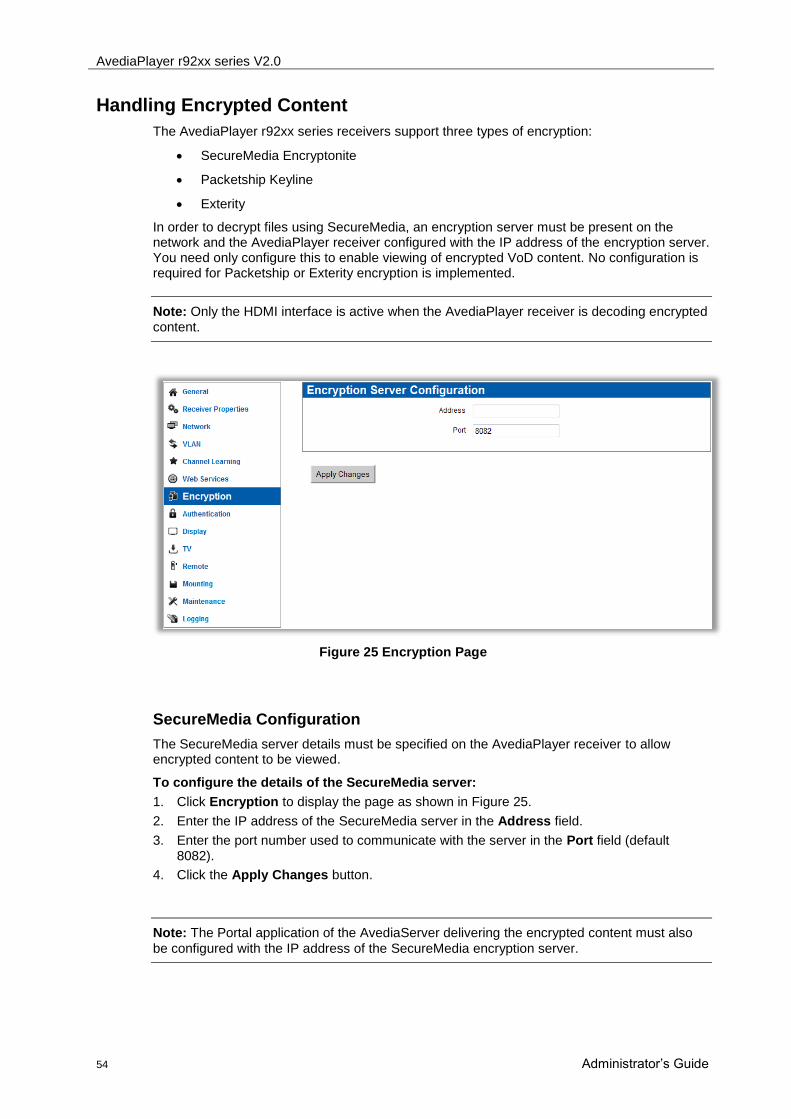
AvediaPlayer r92xx series V2.0
54 Administrator‟s Guide
Handling Encrypted Content
The AvediaPlayer r92xx series receivers support three types of encryption:
SecureMedia Encryptonite
Packetship Keyline
Exterity
In order to decrypt files using SecureMedia, an encryption server must be present on the network and the AvediaPlayer receiver configured with the IP address of the encryption server. You need only configure this to enable viewing of encrypted VoD content. No configuration is required for Packetship or Exterity encryption is implemented.
Note: Only the HDMI interface is active when the AvediaPlayer receiver is decoding encrypted content.
Figure 25 Encryption Page
SecureMedia Configuration
The SecureMedia server details must be specified on the AvediaPlayer receiver to allow encrypted content to be viewed.
To configure the details of the SecureMedia server:
1. Click Encryption to display the page as shown in Figure 25.
2. Enter the IP address of the SecureMedia server in the Address field.
3. Enter the port number used to communicate with the server in the Port field (default 8082).
4. Click the Apply Changes button.
Note: The Portal application of the AvediaServer delivering the encrypted content must also
be configured with the IP address of the SecureMedia encryption server.
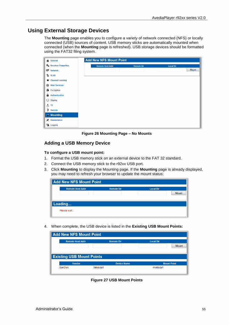
AvediaPlayer r92xx series V2.0
Administrator‟s Guide 55
Using External Storage Devices
The Mounting page enables you to configure a variety of network connected (NFS) or locally connected (USB) sources of content. USB memory sticks are automatically mounted when connected (when the Mounting page is refreshed). USB storage devices should be formatted using the FAT32 filing system.
Figure 26 Mounting Page – No Mounts
Adding a USB Memory Device
To configure a USB mount point:
1. Format the USB memory stick on an external device to the FAT 32 standard.
2. Connect the USB memory stick to the r92xx USB port.
3. Click Mounting to display the Mounting page. If the Mounting page is already displayed, you may need to refresh your browser to update the mount status:
4. When complete, the USB device is listed in the Existing USB Mount Points:
Figure 27 USB Mount Points
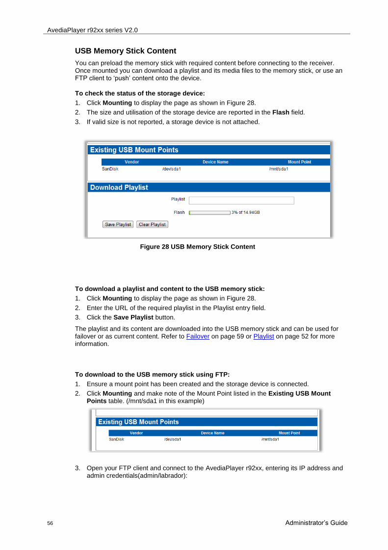
AvediaPlayer r92xx series V2.0
56 Administrator‟s Guide
USB Memory Stick Content
You can preload the memory stick with required content before connecting to the receiver. Once mounted you can download a playlist and its media files to the memory stick, or use an FTP client to „push‟ content onto the device.
To check the status of the storage device:
1. Click Mounting to display the page as shown in Figure 28.
2. The size and utilisation of the storage device are reported in the Flash field.
3. If valid size is not reported, a storage device is not attached.
Figure 28 USB Memory Stick Content
To download a playlist and content to the USB memory stick:
1. Click Mounting to display the page as shown in Figure 28.
2. Enter the URL of the required playlist in the Playlist entry field.
3. Click the Save Playlist button.
The playlist and its content are downloaded into the USB memory stick and can be used for failover or as current content. Refer to Failover on page 59 or Playlist on page 52 for more information.
To download to the USB memory stick using FTP:
1. Ensure a mount point has been created and the storage device is connected.
2. Click Mounting and make note of the Mount Point listed in the Existing USB Mount Points table. (/mnt/sda1 in this example)
3. Open your FTP client and connect to the AvediaPlayer r92xx, entering its IP address and admin credentials(admin/labrador):

AvediaPlayer r92xx series V2.0
Administrator‟s Guide 57
4. Confirm the connection has been made and the mount point path is displayed:
5. Navigate the local directories to locate and transfer the file(s) required.
The file can now be played directly or used as part of the Failover mechanism.
To delete all content from the storage device:
1. Click Maintenance to display the page as shown in.
2. Click the Clear Playlist button.

AvediaPlayer r92xx series V2.0
58 Administrator‟s Guide
Adding a Remote Storage Device
To configure a remote storage NFS mount point:
1. Click Mounting to display the Mounting page.
2. Enter the IP address of the remote host, the remote directory path, and the local directory into the respective Add New NFS Mount Point fields.
3. Click the Mount button to start the mounting process. When successfully mounted, the new mount point is listed in the Existing NFS Mount Points list:
If the mounting process does not succeed, the connection status is displayed as shown:
4. To remove the connection, click the UnMount button.

AvediaPlayer r92xx series V2.0
Administrator‟s Guide 59
Configuring Failover
The AvediaPlayer receiver has 2 mechanisms to ensure content is always displayed if the channel being played fails.
Channel Redundancy – this mechanism checks for availability of another channel of the same name and group membership as the channel which has failed.
Failover – this mechanism involves playing another channel, playing back video file(s) from an NFS mounted storage device, or launching a page to display in the browser.
Channel Redundancy
Channel Redundancy is independent of Failover configuration. For channel redundancy to be effective, a duplicate channel must have the same name and group membership as the original channel. The receiver returns to the original channel when it is re-established. When multiple identical channels exist, each is tried in turn until one is successfully played. If all attempts to play the redundant channel(s) fail, the receiver initiates the failover mechanism (if it is enabled). Refer to the Exterity Gateway, Encoder and AvediaServer documentation for more information about stream naming and group membership.
Note: Redundant (duplicate) channels are not listed in the Program Guide when displayed on
the AvediaPlayer receiver.
Failover
Failover allows you to configure the receiver to respond to the loss of the currently playing channel. When the failed stream returns (on the original address) the receiver automatically switches back to it (if no other channel has been manually selected). No operator intervention is required.
You can configure the following responses:
Play media, either another network streamed channel, or a media file (in transport stream format) located on a local or remote storage device (refer to Using External Storage Devices on page 55 ).
Play a playlist saved to a local storage device or from a remote location (refer to Using External Storage Devices on page 55).
Display a web page using the receiver‟s browser. (Include a stream playing with a browser video object if required.)
Note: If one or more redundant channels have been configured, the receiver will attempt to play these first, only initiating the failover mechanism if the redundant channel(s) also fail.
To failover to media:
1. Click Maintenance to display the page as shown in Figure 15.
2. In the Fail Over section, click the State drop down list to select Enable.
3. In the Fail Over section, click the Backup Channel drop down list to select Media.
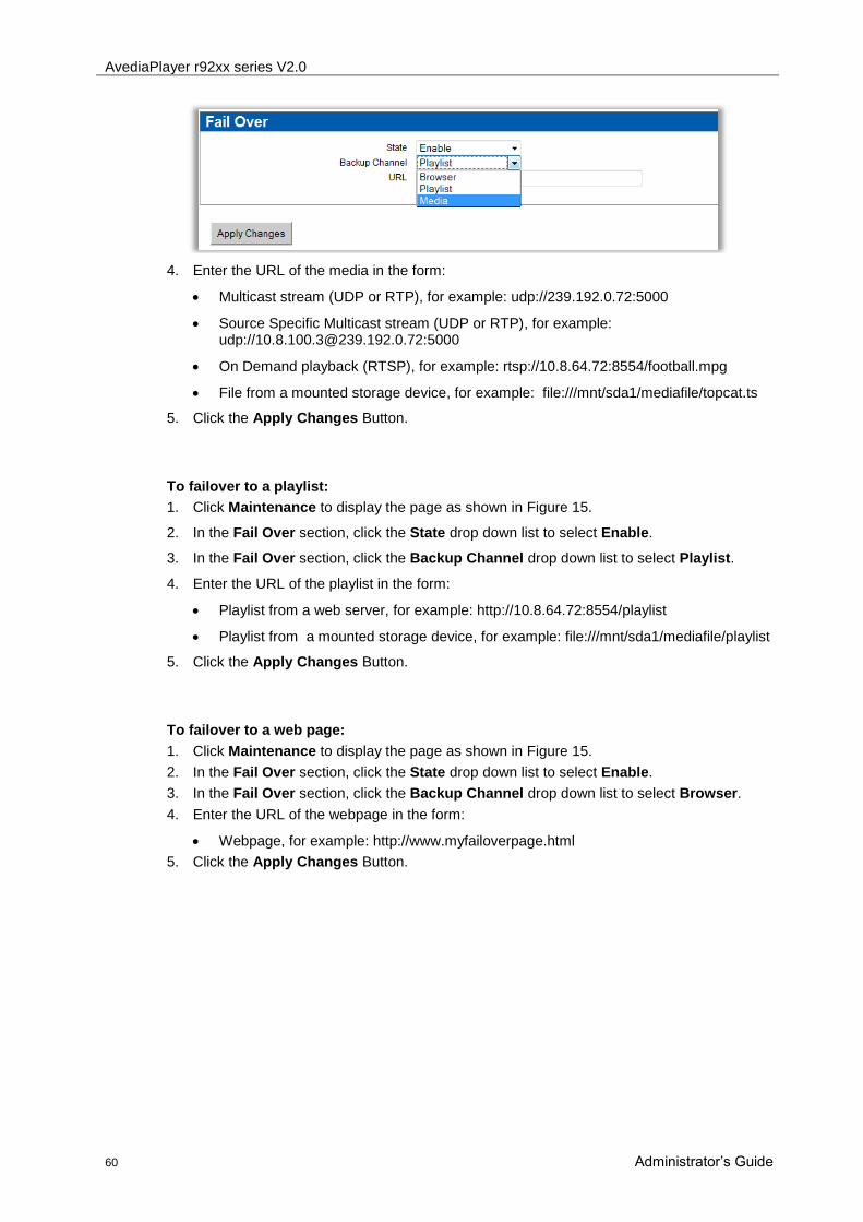
AvediaPlayer r92xx series V2.0
60 Administrator‟s Guide
4. Enter the URL of the media in the form:
Multicast stream (UDP or RTP), for example: udp://239.192.0.72:5000
Source Specific Multicast stream (UDP or RTP), for example: udp://[email protected]:5000
On Demand playback (RTSP), for example: rtsp://10.8.64.72:8554/football.mpg
File from a mounted storage device, for example: file:///mnt/sda1/mediafile/topcat.ts
5. Click the Apply Changes Button.
To failover to a playlist:
1. Click Maintenance to display the page as shown in Figure 15.
2. In the Fail Over section, click the State drop down list to select Enable.
3. In the Fail Over section, click the Backup Channel drop down list to select Playlist.
4. Enter the URL of the playlist in the form:
Playlist from a web server, for example: http://10.8.64.72:8554/playlist
Playlist from a mounted storage device, for example: file:///mnt/sda1/mediafile/playlist
5. Click the Apply Changes Button.
To failover to a web page:
1. Click Maintenance to display the page as shown in Figure 15.
2. In the Fail Over section, click the State drop down list to select Enable.
3. In the Fail Over section, click the Backup Channel drop down list to select Browser.
4. Enter the URL of the webpage in the form:
Webpage, for example: http://www.myfailoverpage.html
5. Click the Apply Changes Button.

AvediaPlayer r92xx series V2.0
Administrator‟s Guide 61
Configuring TV Control
The receiver can be configured to communicate with the attached TV/Display over the Serial TV interface. The receiver can be configured to send commands to the TV on entering and exiting standby mode (whether via remote control handset or management interface), thus powering on/off the TV as appropriate. An additional cable is required to connect the AvediaPlayer receiver Serial port (RJ45 connector) to the TV control port. Connection details are described in APPENDIX E - Serial TV Interface connection.
Note: When the TV/ADM port is configured for use with a TV serial interface it cannot be used
to access the admin interface as described in Chapter 9 Admin Interface on page 65.
In order to use this feature, contact your Exterity supplier to obtain a serial configuration file for your TV (a list of supported TV types is also available from your supplier).
Figure 29 TV Control Page
Serial pass-through mode is also available. This enables the administrator to communicate directly with the attached TV. See APPENDIX D for details on how to use this feature.
To enable the feature, first download the appropriate configuration file to the AvediaPlayer receiver. You can then use the receiver web interface to test sending serial commands to the TV and configure the particular actions to be taken on entering and leaving standby mode.
To enable serial TV control
1. Click TV to display the TV Control page as shown in Figure 29.
2. Click the Type drop down list to select Serial.
3. Click the Apply Changes button.
The Serial Out section is displayed:
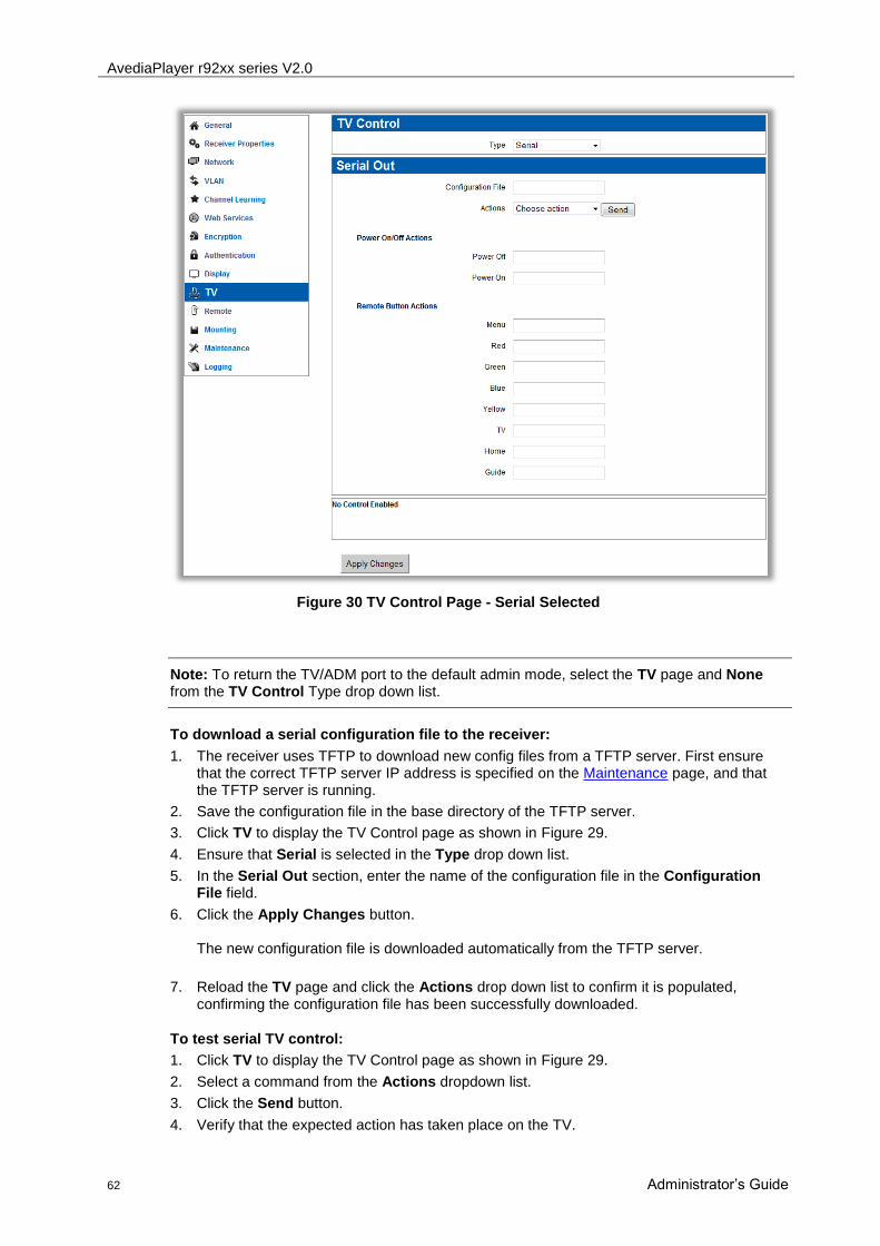
AvediaPlayer r92xx series V2.0
62 Administrator‟s Guide
Figure 30 TV Control Page - Serial Selected
Note: To return the TV/ADM port to the default admin mode, select the TV page and None from the TV Control Type drop down list.
To download a serial configuration file to the receiver:
1. The receiver uses TFTP to download new config files from a TFTP server. First ensure that the correct TFTP server IP address is specified on the Maintenance page, and that the TFTP server is running.
2. Save the configuration file in the base directory of the TFTP server.
3. Click TV to display the TV Control page as shown in Figure 29.
4. Ensure that Serial is selected in the Type drop down list.
5. In the Serial Out section, enter the name of the configuration file in the Configuration File field.
6. Click the Apply Changes button. The new configuration file is downloaded automatically from the TFTP server.
7. Reload the TV page and click the Actions drop down list to confirm it is populated, confirming the configuration file has been successfully downloaded.
To test serial TV control:
1. Click TV to display the TV Control page as shown in Figure 29.
2. Select a command from the Actions dropdown list.
3. Click the Send button.
4. Verify that the expected action has taken place on the TV.

AvediaPlayer r92xx series V2.0
Administrator‟s Guide 63
To configure actions to take on entering/exiting standby mode:
1. Click TV to display the TV Control page as shown in Figure 29.
2. Enter the appropriate actions in the Power On Actions and Power Off Actions fields. These should be commands as shown in the Test Serial Out dropdown. Multiple commands must be separated with a semicolon (;). If a delay is required between commands, use “sleep” followed by a value in seconds. e.g. “tv_on;sleep 2;tv_mute_on”.
3. Click the Apply Changes button.
Configuring Remote Control Functions
The AvediaPlayer r92xx receivers use a configuration file to interpret codes from the remote control handset. The standard handset available from Exterity uses the type
exterity_remote_2.
The General section allows you to enable/disable remote control of the receiver and to specify the use of a different handset to control the receiver by specifying the correct configuration file. If you wish to use a different handset, consult a systems integrator to obtain a configuration file for that handset.
In addition to controlling on-screen menus, you can use the remote control handset to control the AV device attached to an Exterity Encoder (refer to Controlling Remote AV Devices on page 22).
Remote control operation can be disabled completely. The functionality controlled by the menu and colour buttons can be re-configured in the Button Functions section of the page.
Figure 31 Remote Page
General
The General section of the page allows specify the use of the remote control handset, including control of a remote device.
To enable/disable handset control of the AvediaPlayer receiver:
1. Click Remote to display the page as shown in Figure 31.
2. Select Yes to enable the handset, No to disable the handset from the Enable Handset drop down list.
3. Click the Apply Changes button

AvediaPlayer r92xx series V2.0
64 Administrator‟s Guide
To use a different remote control handset:
1. The receiver uses TFTP to download new remote control config files from a TFTP server. First ensure that the correct TFTP server IP address is specified on the Maintenance page, and that the TFTP server is running.
2. Save the configuration file in the following directory on the TFTP server.
<root>/remotes/<manufacturer>/<type>/<manufacturer>_<type>_<id>.conf
For example:
<root>/remotes/sony/dvd/sony_dvd_1.conf
3. Click Remote to display the page as shown in Figure 31.
4. Enter the name of the configuration file in the Receiver Handset Type field.
5. Click the Apply Changes button. The new configuration file is downloaded automatically from the TFTP server. You can confirm the successful download by opening the log file as described in Logging on page 38 and checking for completed TFTP activity.
To enable control of a remote device:
1. Click Remote to display the page as shown in Figure 31.
2. Click the Control remote device drop down list to select Yes.
3. Click the Apply Changes button.
To disable remote control operation:
1. Click Remote to display the page as shown in Figure 31.
2. In the Receiver Handset Type field, clear the contents to leave it empty.
3. Click the Apply Changes button.
Button functions
The default operation of the following buttons is as follows:
Menu: Channels menu
Blue: None
Green: None
Yellow: None
Red: None
TV: Audio/Video
Home: Browser
Guide: EPG (if available)
The functions of all these buttons can be redefined if required. For example, disable use of the HOME button to stop users using the web browser.
To redefine button functions:
1. Click Remote to display the page as shown in Figure 31.
2. In the Button functions section, select and choose the required functions from the drop down list for the associated button.
3. Click the Apply Changes button.
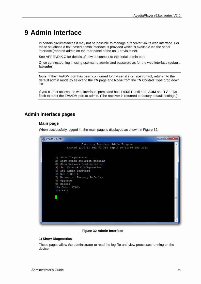
AvediaPlayer r92xx series V2.0
Administrator‟s Guide 65
9 Admin Interface
In certain circumstances it may not be possible to manage a receiver via its web interface. For these situations a text based admin interface is provided which is available via the serial interface (marked admin on the rear panel of the unit) or via telnet.
See APPENDIX C for details of how to connect to the serial admin port.
Once connected, log in using username admin and password as for the web interface (default labrador).
Note: If the TV/ADM port has been configured for TV serial interface control, return it to the default admin mode by selecting the TV page and None from the TV Control Type drop down list. If you cannot access the web interface, press and hold RESET until both ADM and TV LEDs
flash to reset the TV/ADM port to admin. (The receiver is returned to factory default settings.)
Admin interface pages
Main page
When successfully logged in, the main page is displayed as shown in Figure 32.
Figure 32 Admin Interface
1) Show Diagnostics
These pages allow the administrator to read the log file and view processes running on the device.
AvediaPlayer r92xx series V2.0
66 Administrator‟s Guide
2) Show board revision details
Lists the internal hardware revision and serial number
3) Show Network Configuration
Lists network configuration information such as DHCP status and IP address.
4) Set Network Configuration
This page allows the administrator to configure the DHCP setting and the IP address of the device.
5) Set admin password
Allows the administrator to change the admin password for the serial and web interfaces
6) Run a shell
This allows the administrator to run a shell as admin.
7) Return to factory defaults
This page allows the administrator to set all configurations to factory defaults.
8) Upgrade
This allows the administrator to specify the TFTP server and initiate a firmware upgrade.
9) Reboot
Reboots the device.
10) Setup VLANs
This allows the administrator to setup VLANs on the network ports of an AvediaPlayer r9220 receiver.
11) Exit
Closes the Admin Interface

AvediaPlayer r92xx series V2.0
Administrator‟s Guide 67
10 Troubleshooting
Problem Possible Cause Solution
Device does not appear in AvediaServer Director
Network connection faulty or cannot obtain IP address (indicated by LED flash 4 times per second and on-screen message)
Check Ethernet connections or replace cable.
Check that DHCP server is running on network.
AvediaServer Device Listener turned off
Open AvediaServer Status > Service page and turn on Device Listener.
AvediaServer Director cannot communicate with device
Network connection faulty See above
Device has an IP address on a different subnet to the management station
Use a management station configured with an appropriate IP address to manage the device.
Device is upgrading Wait for upgrade to complete
No picture on television Incorrect AV cabling Check cabling.
The wrong AV input is selected on the TV.
Find the appropriate AV input.
Channel(s) missing from channels list
Network connection faulty See above
The head-end device(s) is/are not properly connected to the network.
Ensure Director can communicate with the headend device(s) and investigate if not.
The head-end devices(s) is/are on a different subnet from the receiver.
Configure multicast routing on network.
Groups are configured, but the channel and receiver are not in the same group.
Correct the Groups configuration on the Groups tab.
Cannot connect to channel (“This channel is not available”)
Either receiver or head-end device are not on the network.
Ensure the AvediaServer Director can communicate with the devices and investigate if not.
Blank screen when changing channel
Network port overloaded. Ensure that network is multicast-enabled.
Video freezes or continually stutters
Network port overloaded. Ensure that network is multicast-enabled.
Traffic smoothing on TVgateway is incorrectly configured
Change the traffic smoothing setting.

AvediaPlayer r92xx series V2.0
68 Administrator‟s Guide
Ethernet configuration mismatch with switch.
If auto-negotiation is disabled on the switch port, it should be disabled on the receiver and the devices should have identical settings. If auto-negotiation is enabled on the switch port it should be enable on the receiver.
Cannot connect to URL You are using invalid proxy settings.
Check your proxy settings on Browser tab.
After upgrade, the device is still running the old version of firmware.
The correct firmware file is not on the TFTP server.
Put the correct file on the TFTP server.
The TFTP server address configured for the device is wrong
Check that the TFTP server address is the address of the machine the TFTP server is running on.
The TFTP server is not running. Start the TFTP server.
The TFTP server is not configured to send files.
Fix the security settings on the TFTP server.

AvediaPlayer r92xx series V2.0
Administrator‟s Guide 69
APPENDIX A Playlist Format
Playlist file format
Sample playlist files are shown below:
Example 1 – Remote content from a web server:
media:http://10.8.64.72/video/news1.mpg
media:http://10.8.64.72/video/sport1.mpg
media:http://10.8.64.72/video/news2.mpg
media:http://10.8.64.72/video/cartoon.mpg
media:http://10.8.64.72/video/film.mpg
Example 2 – Local content from a USB Memory Stick:
file:///mnt/sda1/news1.mpg
file:///mnt/sda1/sport.mpg
file:///mnt/sda1/news2.mpg
file:///mnt/sda1/cartoon.mpg
file:///mnt/sda1/film.mpg
Note: The video files must be in transport stream format.

AvediaPlayer r92xx series V2.0
70 Administrator‟s Guide
APPENDIX B XML Channel List Format
Channel list format
A sample XML channel list is shown below:
<channel-list>
<channel number="1">
<name>BBC1</name>
<multicast ip="239.192.33.61" port="5002" />
<dvb sid="4164" />
</channel>
<channel number="2">
<name>BBC2</name>
<multicast ip="239.192.37.61" port="5003" />
<dvb sid="4228" />
</channel>
<channel number="24">
<name>BBC NEWS24</name>
<multicast ip="239.192.32.61" port="5001" />
<dvb sid="4415" vpid="281" apid="282" />
</channel>
</channel-list>
The parameter number within the channel element is optional, as is the dvb element and all its parameters.
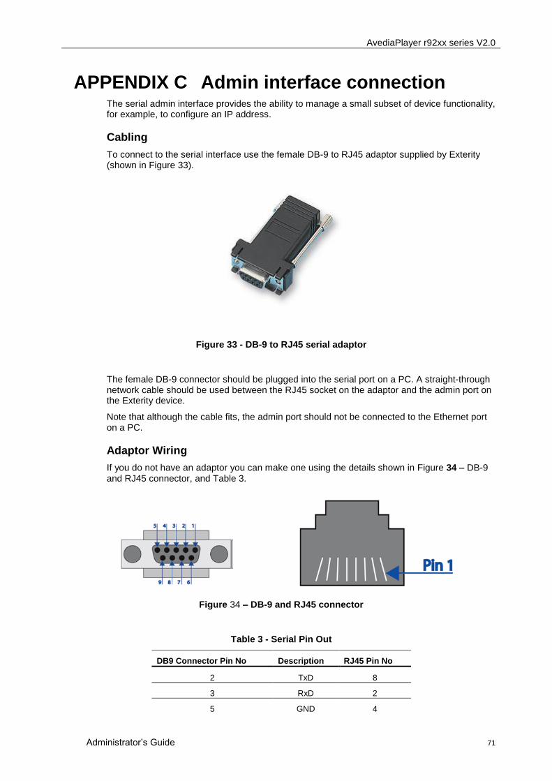
AvediaPlayer r92xx series V2.0
Administrator‟s Guide 71
APPENDIX C Admin interface connection The serial admin interface provides the ability to manage a small subset of device functionality, for example, to configure an IP address.
Cabling
To connect to the serial interface use the female DB-9 to RJ45 adaptor supplied by Exterity (shown in Figure 33).
Figure 33 - DB-9 to RJ45 serial adaptor
The female DB-9 connector should be plugged into the serial port on a PC. A straight-through network cable should be used between the RJ45 socket on the adaptor and the admin port on the Exterity device.
Note that although the cable fits, the admin port should not be connected to the Ethernet port on a PC.
Adaptor Wiring
If you do not have an adaptor you can make one using the details shown in Figure 34 – DB-9 and RJ45 connector, and Table 3.
Figure 34 – DB-9 and RJ45 connector
Table 3 - Serial Pin Out
DB9 Connector Pin No Description RJ45 Pin No
2 TxD 8
3 RxD 2
5 GND 4
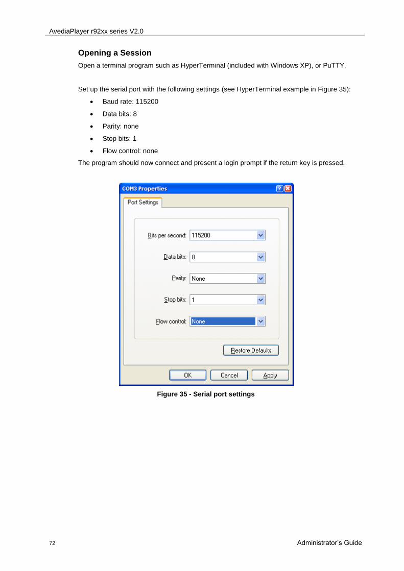
AvediaPlayer r92xx series V2.0
72 Administrator‟s Guide
Opening a Session
Open a terminal program such as HyperTerminal (included with Windows XP), or PuTTY.
Set up the serial port with the following settings (see HyperTerminal example in Figure 35):
Baud rate: 115200
Data bits: 8
Parity: none
Stop bits: 1
Flow control: none
The program should now connect and present a login prompt if the return key is pressed.
Figure 35 - Serial port settings

AvediaPlayer r92xx series V2.0
Administrator‟s Guide 73
APPENDIX D Serial TV Interface connection The serial TV interface allows serial control of an attached television or display. The wiring of this interface is as shown below.
Table 4 - Serial TV interface wiring
Description RJ45 Pin No
TxD 8
RxD 2
GND 4
Figure 36 - Serial TV Interface

AvediaPlayer r92xx series V2.0
74 Administrator‟s Guide
APPENDIX E Serial Pass-through To enable serial pass-through, first add a line of the following form to your serial out configuration file:
<telnet port="5001" enable="yes"/>
Then download the file to the receiver as described in Configuring TV Control on page 61.
You can then use a telnet client to connect to the receiver‟s IP address on the specified port. This will give you slave line access to the attached TV.
Example:
<exterity>
<tv>
<config>
<manufacturer name="lg" version="1" />
<serial baud="9600" parity="none" databits="8" flow="none"
raw="no" />
<telnet port="5001" enable="yes"/>
</config>
</tv>
</exterity>
To enable/disable serial pass-through or change the TCP port, consult the table below.
<telnet> attributes Type Description
Port Integer TCP Port to listen on
enable yes | no To enable or disable serial pass through.
AvediaPlayer r92xx series V2.0
Administrator‟s Guide 75
APPENDIX F Support and contact information Technical Support for Exterity products is provided by authorised Systems Integrators and Resellers. Please contact your Systems Integrator or Reseller with any Support issues.