external modulators
TRANSCRIPT

Lithium Niobate
External Modulators
-By SURESH CHAND JAT
2015PWC5398
WOC(M.Tech)
MNIT JAIPUR
Supervisor
Dr. M. Ravi Kumar
Assistant Professor
Dept. of ECE
MNIT JaipurDate:31-03-2016

Content-
Introduction to Optical Modulation
Direct Modulation
External Modulation
Lithium Niobate External Modulators
Pockel Effect
Directional Coupler
MZI Coupler & Modulator

Optical Modulation
The process of imposing data on light stream is called modulation.
The simplest and most widely used modulation scheme called On
Off Keying (OOK) Where light stream turn on and off based on the
data bits.
Two way of the OOK modulation-
1. Direct Modulation
2. Using External Modulators

Direct Modulation
The message signal is superimposed on the bias current
(dc) which modulates the laser
Robust and simple, hence widely used
Issues: chirp, turn on delay, clipping and laser nonlinearity

Direct Modulation-

External Modulation
Change the transmission characteristics
Change the power of a continuous wave laser
This is of two types-
1. Electro-optical(EO) modulation(using Lithium Niobate
Modulators) (low efficiency)
2.. Electro-absorption (EA) modulation (smaller modulation
bandwidth).
Lithium Niobate External Modulators
The Lithium Niobate modulators makes use of the electro-
optic effect, where an applied voltage induces a change in
refractive index of the material.
The device itself configured as a directional coupler or as
a Mach-Zehnder Interferometer (MZI).

Pockel Effect
The Pockel effect is the linear electro-optic
effect, where the refractive index of a medium is
modified in proportion to the applied electric
field strength.

Pockel Effect in LiNbO3
Suppose x, y and z are principal axes of a crystal with refractive indices n1, n2 and n3 along these directions
For an optically isotropic crystal, these would be the same
For a uniaxial crystal n1= n2 n3
Apply a voltage across a crystal and thereby apply an external dc field Ea along z-axis
In Pockels effect, the field will modify the optical indicatrix.
The exact effect depends on the crystal structure

Pockel Effect in LiNbO3
(a) Cross section of optical indicatrix with no applied field n1=n2=n0
(b) Applied field along Y in LiNbO3 modified the indicatrix and changes n1
and n2 to n’1 and n’2

Pockel Effect in LiNbO3
In the case lithium niobate (uniaxial crystal), a field Ea is applied along the y-direction
It does not significantly rotate the principal axes
changes the principal refractive indices n1 & n2 (both equal to no) to n1’ & n2’ as shown in fig (b)
Consider a wave propagating along the z-direction (optic axis) in the crystal
Before a field Ea is applied, this wave experience n1=n2=nowhatever in the polarization as fig (a)
In the presence of an applied field Ea, the light propagates as two orthogonally polarized waves (parallel to x and y) experiencing different refractive indices n1’ & n2’

Pockel Effect in LiNbO3
The applied field thus induces a birefringence for light
traveling along the z-axis.
The field induced rotation of principal axes is neglected.
The Pockel effect gives the new refractive indices n1’ &
n2’ in the presence of Ea as
n1 ’ n1 + ½ n13 r22 Ea & n2 ’ n2 – ½ n2
3 r22 Ea
where r22 is a constant, called a Pockel coefficient that depends
on the crystal structure and the material.

Directional Coupler
In Directional coupler configuration by applying a voltage(Modulating signal or data
bits) to the coupling region changes its refractive index, which in turns determines
how much power is coupled from the input waveguide 1 to the output waveguide 1.
Shown in figure-

Mach-Zehnder Interferometer (MZI) Coupler
A Mach-Zehnder Interferometer (MZI) is an interferometric device
that makes use of two interfering paths of different lengths to resolve
different wavelengths.
MZI typically constructed in integrated optics consists of two 3dB
couplers interconnect through two paths of different lengths.

MZI Modulator
In optical switching, induced phase shift by applied voltage can be
converted to an amplitude variation by using an interferometer
Interferometer is a device that interferes two waves of the same
frequency but different phase
Compared to Directional coupler MZI offers a higher modulation
speed for a given drive voltage and provides a higher extinction
ratio.

MZI Modulator

MZI Modulator
Consider the structure shown in Fig, which has implanted single mode waveguide in a LiNbO3 substrate in the geometry.
The waveguide at the input braches out at C to two arms A and B
These arms are later combined at D to constitute the output
The splitting at C and combining at D involve a simple Y-junction waveguides
In the ideal case, the power is equally split at C so that the field is scaled into each arm
The structure acts as an interferometer because the two waves traveling through the arm A and B interfere at the output port D
The output amplitude depends on the phase difference (optical path difference) between A and B branches

MZI Modulator
Two back-to-back identical phase modulatorsenable the phase changes in A and B to be modulated. The applied field in branch A is in opposite direction
to that in branch B
The refractive index changes are opposite and phase changes in arm A and B are also opposite
If applied voltage induces a phase change of p/2in arm A, this will be –p/2 in arm B so that A & B would be out of phase by p. These two waves will interfere destructively and
cancel each other at D.
The output intensity would be zero


MZI Modulator
Since the applied voltage controls the phase difference between the two interfering waves A and B at the output
This voltage also control the output light intensity (the relationship is not linear)
The relative phase difference between the two waves A and B is doubled with respect to a phase change f in a single arm
The switching intensity can be predicted by adding waves A and B at D with A as amplitude of wave A & B:
Eoutput A cos(wt+f) + A cos(wt–f) = 2A cosf coswt
MZI Modulator
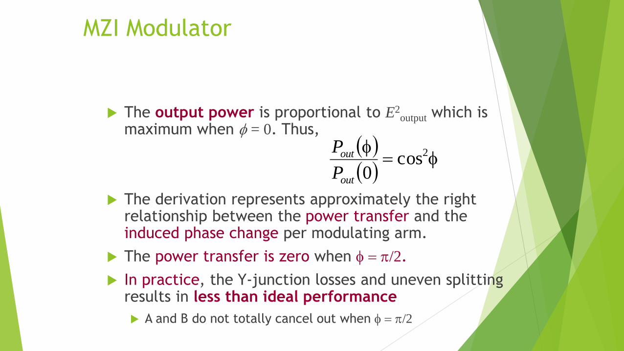
The output power is proportional to E2output which is
maximum when f = 0. Thus,
The derivation represents approximately the right relationship between the power transfer and the induced phase change per modulating arm.
The power transfer is zero when f = p/2.
In practice, the Y-junction losses and uneven splitting results in less than ideal performance
A and B do not totally cancel out when f = p/2
f=f 2cos0out
out
P
P


Thank You