external post-tensioning system · the pt system is intended to be used for the prestressing of...
TRANSCRIPT

BBR
VT
CO
NA
CM
EEx
tern
al P
ost-t
ensi
onin
g Sy
stem
European Technical ApprovalETA – 07/0168

0432
ETA-07/0168BBR VT CONA CME
External Post-tensioning System
BBR VT International LtdRingstrasse 2, 8603 Schwerzenbach (Switzerland)
www.bbrnetwork.com
0432-CPD-11 9181-3/213
Responsible BBR PT Specialist Company
The delivery note accompanying components of the BBR VT CONA CME Post-tensioning System will contain the CE marking.
Assembly and installation of BBR VT CONA CME tendons must only be carried out by qualified BBR PT Specialist Companies. Find the local BBR PT Specialist Company by visiting the BBR Network website www.bbrnetwork.com.
European Organisation for Technical ApprovalsEuropäische Organisation für Technische ZulassungenOrganisation Européenne pour l’Agrément technique
Guideline for European Technical Approval of Post-tensioning Kits for Prestressing of Structures
Requirements for the installation of post-tensioning kits for prestressing of structures and qualification of the specialist company and its personnel
BBR E-Trace is the trading and quality assurance platform of the BBR Network linking the Holder of Approval, BBR VT International Ltd, BBR PT Specialist Companies and the BBR Manufacturing Plant. Along with the established BBR Factory Production Control, BBR E-Trace provides effective supply chain management including installation, delivery notes and highest quality standards, as well as full traceability of components.
Year
PT Specialist Company
Company
ww
w.bbrnetwork.com
ETAG 013
CWA 14646
S P E C I ME N

elec
tron
ic c
opy
elec
tron
ic c
opy
elec
tron
ic c
opy
elec
tron
ic c
opy
ele
ctro
nic
copy
e
lect
roni
c co
py
European technical approval ETA-07/0168English translation, the original version is in German
Handelsbezeichnung BBR VT CONA CME – Externes Spannverfahren Trade name BBR VT CONA CME – External Post-tensioning System
Zulassungsinhaber Holder of approval
BBR VT International Ltd. Bahnstrasse 23 CH-8603 Schwerzenbach (ZH) Switzerland
Zulassungsgegenstand und Verwendungszweck
Litzen-Spannverfahren, extern, für das Vorspannen von Tragwerken
Generic type and use of construction product Post-tensioning kit for external prestressing of structures
Geltungsdauer vom Validity from
20.12.2012
bis zum to
19.12.2017
HerstellwerkManufacturing plant
BBR VT International Ltd. Bahnstrasse 23 CH-8603 Schwerzenbach (ZH) Switzerland
Diese Europäische technische Zulassung umfasst 37 Seiten einschließlich 16 Anhängen
This European technical approval contains 37 Pages including 16 Annexes
Diese Europäische Technische Zulassung verlängert
ETA-07/0168 mit Geltungsdauer vom 20.12.2007 bis zum 19.12.2012
This European technical approval extends ETA-07/0168 with validity from 20.12.2007 to 19.12.2012

Page 2 of European technical approval ETA-07/0168 Validity from 20.12.2012 to 19.12.2017, extends ETA-07/0168 with validity from 20.12.2007 to 19.12.2012
OIB-250-006/06-056
elec
tron
ic c
opy
elec
tron
ic c
opy
elec
tron
ic c
opy
elec
tron
ic c
opy
ele
ctro
nic
copy
e
lect
roni
c co
py
I LEGAL BASES AND GENERAL CONDITIONS
1 This European technical approval is issued by Österreichisches Institut für Bautechnik in accordance with:
1. Council Directive 89/106/EEC of 21 December 1988 on the approximation of laws, regulations and administrative provisions of Member States relating to construction products1 – Construction Products Directive (CPD) –, amended by the Council Directive 93/68/EEC of 22 July 19932, and Regulation (EC) 1882/2003 of the European Parliament and of the Council of 29 September 20033;
2. dem Salzburger Bauproduktegesetz, LGBl. Nr. 11/1995, in der Fassung LGBl. Nr. 47/1995, LGBl. Nr. 63/1995, LGBl. Nr. 123/1995, LGBl. Nr. 46/2001, LGBl. Nr. 73/2001, LGBl. Nr. 99/2001 und LGBl. Nr. 20/2010;
the Salzburg Construction Product Regulation LGBl. 11/1995, amended by LGBl. 47/1995, LGBl. 63/1995, LGBl. 123/1995, LGBl. 46/2001, LGBl. 73/2001, LGBl. 99/2001, and LGBl. 20/2010;
3. Common Procedural Rules for the Requesting, Preparing and Granting of European technical approvals set out in the Annex of Commission Decision 94/23/EC4;
4. Guideline for European technical approval of Post-Tensioning Kits for Prestressing of Structures, ETAG 013, Edition June 2002.
2 Österreichisches Institut für Bautechnik is authorised to check whether the provisions of this European technical approval are met. Checking may take place at the manufacturing plant. Nevertheless, the responsibility for the conformity of the products to the European technical approval and for their fitness for the intended use remains with the holder of the European technical approval.
3 This European technical approval shall not be transferred to manufacturers or agents of manufacturers other than those indicated on Page 1, or manufacturing plants other than those indicated on Page 1 of this European technical approval.
4 This European technical approval may be withdrawn by Österreichisches Institut für Bautechnik, in particular pursuant to information by the Commission on the according to Article 5 (1) of the Council Directive 89/106/EEC.
5 Reproduction of this European technical approval including transmission by electronic means shall be in full. However, partial reproduction can be made with the written consent of Österreichisches Institut für Bautechnik. In this case partial reproduction has to be designated as such. Texts and drawings of advertising brochures shall not contradict or misuse the European technical approval.
6 The European technical approval is issued by the Approval Body in its official language. This version corresponds to the version circulated within EOTA. Translations into other languages have to be designated as such.
1 Official Journal of the European Communities L 40, 11.02.1989, page 12 2 Official Journal of the European Communities L 220, 30.08.1993, page 1 3 Official Journal of the European Union L 284, 31.10.2003, page 1 4 Official Journal of the European Communities L 17, 20.01.1994, page 34

Page 3 of European technical approval ETA-07/0168 Validity from 20.12.2012 to 19.12.2017, extends ETA-07/0168 with validity from 20.12.2007 to 19.12.2012
OIB-250-006/06-056
elec
tron
ic c
opy
elec
tron
ic c
opy
elec
tron
ic c
opy
elec
tron
ic c
opy
ele
ctro
nic
copy
e
lect
roni
c co
py
II SPECIFIC CONDITIONS OF THE EUROPEAN TECHNICAL APPROVAL
1 Definition of product and intended use
1.1 Definition of product
This European technical approval (ETA) applies to a kit, the PT system
BBR VT CONA CME –External Post-tensioning System,
comprising the following components, see Annex 1:
− Tendon
External tendons with 04 to 31 tensile elements.
− Tensile element
7-wire prestressing steel strand with nominal diameters and nominal tensile strength as given in Table 1.
Table 1: Tensile elements
Nominal diameter Nominal cross-sectional area
Maximum characteristic tensile strength
mm mm2 MPa
15.3 140
15.7 150 1,860
Note 1 MPa = 1 N/mm2
− Anchorage and coupler
Anchorage of the strands with ring wedges;
End anchorage
Fixed (passive) anchor or stressing (active) anchor as end anchorage for 04, 07, 09, 12, 15, 19, 22, 24, 27 and 31 strands;
Fixed coupler
Single plane coupler (FK) for 04, 07, 09, 12, 15, 19, 22, 24, 27 and 31 strands
Sleeve coupler (FH) for 04, 07, 09, 12, 15, 19, 22, 24, 27 and 31 strands;
− Bearing trumplate for 04, 07, 09, 12, 15, 19, 22, 24, 27 and 31 strands;
− Helix and additional reinforcement in the anchorage zone;
− Corrosion protection for tensile elements, couplers and anchorages.
1.2 Intended use
The PT system is intended to be used for the prestressing of structures.
Use categories according to type of tendon and material of structure:
− External tendon where the tendon path is situated outside the cross section of the structure but inside its envelope for normal weight concrete in concrete and composite structures;
− For special structures according to Eurocode 2, Eurocode 4 and Eurocode 6.
Optional use category:
− Restressable tendon
The provisions made in this European technical approval are based on an assumed intended working life of the PT system of 100 years. The indications given on the working life of the PT system cannot

Page 4 of European technical approval ETA-07/0168 Validity from 20.12.2012 to 19.12.2017, extends ETA-07/0168 with validity from 20.12.2007 to 19.12.2012
OIB-250-006/06-056
elec
tron
ic c
opy
elec
tron
ic c
opy
elec
tron
ic c
opy
elec
tron
ic c
opy
ele
ctro
nic
copy
e
lect
roni
c co
py
be interpreted as a guarantee given by the manufacturer or the Approval Body, but are to be regarded only as a means for selecting the appropriate product in relation to the expected, economically reasonable working life of the construction works.
2 Characteristics of the product and methods of verification
PT system 2.1 Designation and range of the anchorages and couplers
2.1.1 General
End anchorages can be used as fixed and stressing anchors. Couplers are fixed couplers. The principal dimensions of anchorages and couplers are given in the Annexes 2 to 4 and 8 to 10.
2.1.2 Designation
End anchorage, e.g. S A CONA CME 1906-150 1860
Stressing (S) or fixed (F)
Anchor head
Designation of the tendon with information on the number, cross sectional area and characteristic tensile strength of the strands
Coupler, e.g. F K CONA CME 1906-150 1860
Fixed coupler
Coupler anchor head K or H
Designation of the tendon with information on the number, cross sectional area and characteristic tensile strength of the strands
2.1.3 Anchorage
2.1.3.1 General
The anchor heads of stressing and fixed anchorages are identical. A differentiation is needed for the construction works.
The wedges of inaccessible fixed anchors shall be secured with springs and/or a wedge retaining plate. An alternative is prelocking each single strand with ~ 0.5 ⋅ Fpk and applying a wedge retaining plate.
Where
Fpk .......... Nominal value of maximum force of single strand
2.1.3.2 Restressable tendon
Significant to a restressable tendon is the excess length of the strands. The extent of the excess length depends on the jack used for restressing. The protrusions of the strands require a permanent corrosive protection and an adapted cap.
2.1.4 Fixed coupler
2.1.4.1 General
The prestressing force at the second construction stage may not be greater than that at the first construction stage, neither during construction, nor in the final state, nor due to any load combination.
2.1.4.2 Single plane coupler FK
The coupling is achieved by means of a coupler anchor head K. The strands of the first construction stage are anchored by means of wedges in machined cones, drilled in parallel. The arrangement of the cones of the first construction stage is identical to that of the anchor heads of the stressing and fixed anchorages. The strands of the second construction stage are anchored in

Page 5 of European technical approval ETA-07/0168 Validity from 20.12.2012 to 19.12.2017, extends ETA-07/0168 with validity from 20.12.2007 to 19.12.2012
OIB-250-006/06-056
elec
tron
ic c
opy
elec
tron
ic c
opy
elec
tron
ic c
opy
elec
tron
ic c
opy
ele
ctro
nic
copy
e
lect
roni
c co
py
a circle around the cones of the first construction stage by means of wedges in machined cones, drilled at an inclination of 7 °.The wedges for the second construction stage are secured by means of holding springs and a cover plate.
2.1.4.3 Sleeve coupler FH
The coupler anchor head H is of the same basic geometry as the anchor head of the fixed and stressing anchors. Compared to the anchor head of the fixed and stressing anchors, the coupler anchor head H is higher and provides an external thread for the coupler sleeve.
The connection between the coupler anchor heads H of the first and second construction stages is achieved by means of a coupler sleeve.
2.1.5 Layout of the anchorage recess
All anchor heads shall be placed perpendicular to the axis of the tendon, see Annex 7.
The dimensions of the anchorage recess shall be adapted to the prestressing jack used. The ETA holder shall save for reference information on the minimum dimensions of the anchorage recess.
The formwork for the anchorage recess should be slightly conical for ease of removal.
In case of an anchorage fully embedded in concrete, the recess shall be designed so as to permit a reinforced concrete cover with the required dimensions, and in any case with a thickness of at least 20 mm.
In case of an exposed anchorage not fully embedded in concrete, there is no concrete cover for the anchorage and bearing trumplate. The exposed surfaces of the bearing trumplate and the cap shall be provided with an appropriate corrosion protection.
2.2 Designation and range of the tendons
2.2.1 Designation
Tendon, e.g. CONA CME 1906-150 1860
External PT
Number of strands (04 to 31)
Type of strand
Cross-sectional area of strand (140 or 150 mm2)
Characteristic tensile strength of strand
The tendons comprise 04 to 31 tensile elements, seven wire prestressing steel strands according to Annex 15.
2.2.2 Range
Prestressing and overtensioning forces are given in the corresponding standards and regulations in force at the place of use. The maximum prestressing and overstressing forces are listed in Table 14.
The tendons consist of 04, 07, 09, 12, 15, 19, 22, 24, 27 and 31 strands. By omitting strands in the anchorages and couplers in the best possible radial symmetrical way, also tendons with numbers of strands lying between the numbers given above can be installed. An unnecessary hole shall either remain undrilled or shall be sealed with a short piece of strand and wedges shall be inserted. For coupler anchor head K the cones of the outer pitch circle, second construction stage, may be equally redistributed if strands are omitted. However, the overall dimensions of the coupler anchor head K shall remain unchanged.
2.2.2.1 CONA CME n06-140
7-wire prestressing steel strand
Nominal diameter ...................................................15.3 mm
Nominal cross-sectional area..................................140 mm2
Maximum characteristic tensile strength..............1,860 MPa

Page 6 of European technical approval ETA-07/0168 Validity from 20.12.2012 to 19.12.2017, extends ETA-07/0168 with validity from 20.12.2007 to 19.12.2012
OIB-250-006/06-056
elec
tron
ic c
opy
elec
tron
ic c
opy
elec
tron
ic c
opy
elec
tron
ic c
opy
ele
ctro
nic
copy
e
lect
roni
c co
py
Table 2: CONA CME n06-140
Number of strands N --- 04 07 09 12 15 19 22 24 27 31
Nominal cross-sectional area of prestressing steel
Ap mm2 560 980 1,260 1,680 2,100 2,660 3,080 3,360 3,780 4,340
Nominal mass of prestressing steel M kg/m 4.37 7.65 9.84 13.12 16.40 20.77 24.05 26.23 29.51 33.88
Characteristic tensile strength fpk = 1,770 MPa
Characteristic ultimateresistance of tendon
Fpk kN 992 1,736 2,232 2,976 3,720 4,712 5,456 5,952 6,696 7,688
Characteristic tensile strength fpk = 1,860 MPa
Characteristic ultimateresistance of tendon
Fpk kN 1,040 1,820 2,340 3,120 3,900 4,940 5,720 6,240 7,020 8,060
2.2.2.2 CONA CME n06-150
7-wire prestressing steel strand
Nominal diameter ...................................................15.7 mm
Nominal cross-sectional area..................................150 mm2
Maximum characteristic tensile strength..............1,860 MPa
Table 3: CONA CME n06-150
Number of strands N --- 04 07 09 12 15 19 22 24 27 31
Nominal cross-sectional area of prestressing steel
Ap mm2 600 1,050 1,350 1,800 2,250 2,850 3,300 3,600 4,050 4,650
Nominal mass of prestressing steel M kg/m 4.69 8.20 10.55 14.06 17.58 22.27 25.78 28.13 31.64 36.33
Characteristic tensile strength fpk = 1,770 MPa
Characteristic ultimateresistance of tendon
Fpk kN 1,064 1,862 2,394 3,192 3,990 5,054 5,852 6,384 7,182 8,246
Characteristic tensile strength fpk = 1,860 MPa
Characteristic ultimateresistance of tendon
Fpk kN 1,116 1,953 2,511 3,348 4,185 5,301 6,138 6,696 7,533 8,649

Page 7 of European technical approval ETA-07/0168 Validity from 20.12.2012 to 19.12.2017, extends ETA-07/0168 with validity from 20.12.2007 to 19.12.2012
OIB-250-006/06-056
elec
tron
ic c
opy
elec
tron
ic c
opy
elec
tron
ic c
opy
elec
tron
ic c
opy
ele
ctro
nic
copy
e
lect
roni
c co
py
2.3 Duct
2.3.1 General
The inner diameter of the duct shall meet the requirements of Table 4.
f = cross sectional area of prestressing steel
cross sectional area of inner diameter of duct
kD = Inner diameter of the duct
cross sectional area of prestressing steel
Where
f ....... degree of filling
kD..... duct coefficient
Table 4: Degree of filling and duct coefficient
f kD1)
Minimum 2) 0.45 1.68
Standard 0.40 1.79
Long tendons 0.30 – 0.35 2.05 – 1.90
Notes 1).......Minimum value according to ENV 1992-1-55, clause 1.6 2).......Not for wax injection in case of PE-duct
Table 5: Minimum radius of curvature and minimum wall thickness
Number of strands 04 07 09 12 15 19 22 24 27 31
Minimum Radius Rmin m 2.0 2.0 2.5 2.7 3.0 3.0 3.2 3.3 3.5 4.0
Plastic Duct tmin mm 5.6 6.0 6.0 6.0 6.0 6.6 7.1 7.4 7.9 8.3
Steel Duct tmin mm 1.5 1.5 1.5 1.5 2.0 2.0 2.0 2.0 2.5 2.5
Notes tmin .........Minimum wall thickness Rmin........Minimum radius of curvature
Exemplary values of duct sizes are shown in Annexes 8 to 10.
Jointing and sealing of the ducts can be performed by welding or non welding jointing techniques, e.g. sleeves and collars. If the joints have to resist to the injection pressure according to ENV 1992-1-5 an internal pressure of at least 1 N/mm2 shall be maintained.
2.3.2 Plastic duct
Plastic ducts shall comply with EN 12201 and, if not installed in a closed hollow box girder, shall be resistant to UV radiation. In general, for tendons with a maximum of 12 strands ducts made of PE 80 or PE 100, class PN 10 may be used, while for larger tendons class PN 6 is sufficient. A frequently used method for jointing is mirror welding.
The minimum wall thicknesses given in Table 5 are appropriate for the minimal radius and grout or grease as filling material. It is permitted to reduce these values by 15 % for a Radius R 1.5 ⋅ Rmin.In case of wax injection the values of Table 5 shall be increased by 15 %.
5 Standards and Guidelines and other documents referred to in this European technical approval are listed in Annex 16.

Page 8 of European technical approval ETA-07/0168 Validity from 20.12.2012 to 19.12.2017, extends ETA-07/0168 with validity from 20.12.2007 to 19.12.2012
OIB-250-006/06-056
elec
tron
ic c
opy
elec
tron
ic c
opy
elec
tron
ic c
opy
elec
tron
ic c
opy
ele
ctro
nic
copy
e
lect
roni
c co
py
2.3.3 Steel Duct
Steel ducts shall comply with EN 10255, EN 10216-1, EN 10217-1, EN 10219-1 or EN 10305-5.
2.4 Friction losses
For the calculation of loss of prestressing force due to friction Coulomb’s law applies. The calculation of the friction losses is carried out using the equation
Fx = F0 · e- μ · α
Where
Fx............ kN ................. prestressing force at a distance x along the tendon
F0............ kN ................. prestressing force at x = 0 m
μ ............. rad-1 .............. friction coefficient, see Table 6
α ............. rad ................ sum of the angular displacements over the distance x, irrespective of direction or sign
x ............. m................... distance along the tendon from the point where the prestressing force is equal to F0
Note 1 1 rad = 1 m/m = 1
Note 2 Wobble effects may be neglected for external tendons.
Table 6: Friction losses
HDPE Steel
Tendon ΔFs μ μ
--- % rad-1 rad-1
CONA CME 0406 1.2
CONA CME 0706 1.1
CONA CME 0906 1.0
CONA CME 1206 to 3106 0.9
0.10to
0.12
0.16to
0.24
Where
ΔFs....... friction loss in anchorages and first construction stage of fixed couplers. It shall be taken into account for determining of the elongation and the prestressing force along the tendon.
2.5 Slip at anchorages and couplers
Slip at stressing and fixed anchorages and at fixed couplers, first and second construction stages, is 6 mm. At the stressing anchorage and at the first construction stage of fixed couplers the slip is 4 mm, provided a prestressing jack with a wedge system and a wedging force of around 25 kN per strand is used.
2.6 Centre spacing and edge distance for anchorages
In general, spacing and distances shall not be less than the values given in Tables 7 and 8 and Annexes 8 to 10.
However, a reduction of up to 15 % of the centre spacing of tendon anchorages in one direction is permitted, but should not be less than the outside diameter of the helix and placing of additional

Page 9 of European technical approval ETA-07/0168 Validity from 20.12.2012 to 19.12.2017, extends ETA-07/0168 with validity from 20.12.2007 to 19.12.2012
OIB-250-006/06-056
elec
tron
ic c
opy
elec
tron
ic c
opy
elec
tron
ic c
opy
elec
tron
ic c
opy
ele
ctro
nic
copy
e
lect
roni
c co
py
reinforcement shall still be possible. In this case the spacing in the perpendicular direction shall be increased by the same percentage. The corresponding edge distance is calculated by
ae = ac2 – 10 + c
be = bc2 – 10 + c
Where
ac ............ mm................ Centre spacing
bc ............ mm................ Centre spacing in the direction perpendicular to ac
ae............ mm................ Edge distance
be............ mm................ Edge distance in the direction perpendicular to ae
c ............. mm................ Concrete cover
The minimum values for ac and bc are given in Annexes 8 to 10.
Standards and regulations on concrete cover in force at the place of use shall be complied with.
Table 7: Minimum centre spacing of tendon anchorages
Tendon Minimum centre spacing ac = bc
fcm, 0, cube 150 MPa 23 28 34 38 43
fcm, 0, cylinder ∅ 150 MPa 19 23 28 31 35
CONA CME 0406 mm 235 215 195 190
CONA CME 0706 mm 310 285 260 250 240
CONA CME 0906 mm 350 320 295 280
CONA CME 1206 mm 405 370 340 325 310
CONA CME 1506 mm 455 415 380 365 345
CONA CME 1906 mm 510 465 425 410 390
CONA CME 2206 mm 550 500 460 440 420
CONA CME 2406 mm 575 525 480 460 435
CONA CME 2706 mm 610 555 505 485 460
CONA CME 3106 mm 650 595 545 520 495
Table 8: Minimum edge distance of tendon anchorages
Tendon Minimum edge distance ae = be
fcm, 0, cube 150 MPa 23 28 34 38 43
fcm, 0, cylinder ∅ 150 MPa 19 23 28 31 35
CONA CME 0406 mm 110 + c 100 + c 90 + c 85 + c
CONA CME 0706 mm 145 + c 135 + c 120 + c 115 + c 110 + c
CONA CME 0906 mm 165 + c 150 + c 140 + c 130 + c
CONA CME 1206 mm 195 + c 175 + c 160 + c 155 + c 145 + c

Page 10 of European technical approval ETA-07/0168 Validity from 20.12.2012 to 19.12.2017, extends ETA-07/0168 with validity from 20.12.2007 to 19.12.2012
OIB-250-006/06-056
elec
tron
ic c
opy
elec
tron
ic c
opy
elec
tron
ic c
opy
elec
tron
ic c
opy
ele
ctro
nic
copy
e
lect
roni
c co
py
Tendon Minimum edge distance ae = be
fcm, 0, cube 150 MPa 23 28 34 38 43
fcm, 0, cylinder ∅ 150 MPa 19 23 28 31 35
CONA CME 1506 mm 220 + c 200 + c 180 + c 175 + c 165 + c
CONA CME 1906 mm 245 + c 225 + c 205 + c 195 + c 185 + c
CONA CME 2206 mm 265 + c 240 + c 220 + c 210 + c 200 + c
CONA CME 2406 mm 280 + c 255 + c 230 + c 220 + c 210 + c
CONA CME 2706 mm 295 + c 270 + c 245 + c 235 + c 220 + c
CONA CME 3106 mm 315 + c 290 + c 265 + c 250 + c 240 + c
Where
fcm, 0, cube 150 ..............Mean concrete compressive strength at time of stressing, determined at cubes, 150 mm
fcm, 0, cylinder ∅ 150.........Mean concrete compressive strength at time of stressing, determined at cylinders, diameter 150 mm
2.7 Minimum radii of curvature
In Table 5 the minimum radii of curvature of the tendon, Rmin, are given versus the number of strands in the tendon. For smaller radii stresses in tensile elements and wear of the duct shall be verified.
2.8 Concrete strength at time of stressing
Concrete complying with EN 206-1 shall be used. At the time of stressing the mean concrete compressive strength, fcm, 0, shall be at least as given in Table 9. The concrete test specimen shall be subjected to the same hardening conditions as the structure.
For partial prestressing with 30 % of the full prestressing force the actual mean value of the concrete compressive strength shall be at least 0.5 · fcm, 0, cube or 0.5 · fcm, 0, cylinder. Intermediate values may be interpolated linearly according to EN 1992-1-1.
Table 9: Compressive strength of concrete
Mean concrete strength, fcm, 0
Cube strength, fcm, 0, cube150 mm cube MPa 23 28 34 38 43
Cylinder strength, fcm, 0, cylinder150 mm cylinder diameter MPa 19 23 28 31 35
The helix, additional reinforcement, centre spacing and edge distance corresponding to the concrete compressive strengths shall be taken from Annexes 8 to 10, see also clauses 2.11.6 and 4.2.4.
2.9 Deviator
The deviator has to transfer the transversal (radial to the deviator) and longitudinal (tangential to the deviator) forces generated by the tendon to the structure. Moreover, deviators have to provide a smooth surface for the tendon. The deviator can be made of concrete, steel or equivalent in respect to the structural and surface requirements. Permanent inserts for deviators of concrete can be made of PE-HD or steel or equivalent in meeting the surface requirements.

Page 11 of European technical approval ETA-07/0168 Validity from 20.12.2012 to 19.12.2017, extends ETA-07/0168 with validity from 20.12.2007 to 19.12.2012
OIB-250-006/06-056
elec
tron
ic c
opy
elec
tron
ic c
opy
elec
tron
ic c
opy
elec
tron
ic c
opy
ele
ctro
nic
copy
e
lect
roni
c co
py
To avoid any kinking of the tendon it is recommended to provide an additional deviation, , of ≥ 3 °, see Annex 6.
For grouting or filling ducts with grease, vents shall be provided or vacuum grouting shall be applied.
2.9.1 Single tube deviator
The deviator is a pre-bent tube that is part of the tendon conduit, see Annex 6. The duct of the tendon is jointed to both ends of the tube.
The jointing between duct and deviator can be by sleeves, collars or by welding
2.9.2 Double tube deviator
The deviator is a pre-formed recess unit of the structure that is not part of the tendon conduit. The duct of the tendon is passed through the recess unit, see Annex 6.
Components2.10 Strands
Only 7-wire prestressing steel strands with characteristics according to Table 10 shall be used, see also Annex 15.
Table 10: Prestressing steel strands
Maximum characteristic tensile strength 1) fpk MPa 1,860
Nominal diameter d Mm 15.3 15.7
Nominal cross-sectional area Ap mm2 140 150
Mass of prestressing steel m kg/m 1.093 1.172
Note1) ...... Prestressing steel strands with a characteristic tensile strength below
1,860 MPa may also be used.
In a single tendon only strands spun in the same direction shall be used. To avoid confusion at a given construction site, only strands of the same nominal diameter and the same characteristic tensile strength shall be used.
2.11 Anchorages and couplers
The components of anchorages and couplers shall comply with the specifications given in Annexes 2 to 4 and in the technical documentation6. Therein the component dimensions, materials and material identification data with tolerances are given.
2.11.1 Anchor heads
The anchor heads are made of steel and provide regularly arranged conical holes drilled in parallel to accommodate prestressing steel strands and wedges. In addition, threaded bores may be provided to fix protective caps and wedge retaining plates. At the back of the anchor head there may be a step for ease of centring the anchor head on the bearing trumplate.
2.11.2 Bearing trumplates
The bearing trumplates made of cast iron transmit the force via 3 load transfer planes to the concrete. Air-vents are situated at the top and at the interface plane to the anchor head. A ventilation tube can be fitted to these air-vents. On the tendon-side end there is an inner thread to accommodate the trumpet.
6 The technical documentation of this European technical approval is deposited with Österreichisches Institut für Bautechnik and, in so
far as it is relevant to the tasks of the approved body involved in the attestation of conformity procedure, it is handed over to the approved body.

Page 12 of European technical approval ETA-07/0168 Validity from 20.12.2012 to 19.12.2017, extends ETA-07/0168 with validity from 20.12.2007 to 19.12.2012
OIB-250-006/06-056
elec
tron
ic c
opy
elec
tron
ic c
opy
elec
tron
ic c
opy
elec
tron
ic c
opy
ele
ctro
nic
copy
e
lect
roni
c co
py
2.11.3 Trumpets
The conical trumpets A for the anchorages are made of PE and have either a corrugated or a plain surface. At the duct side end there is a radius with a smooth surface for the deviation of the strand, to ensure a smooth transition to the duct. The opposite end is connected to the bearing trumplate by an external thread.
The conical trumpets CME-K and CME-H are made of steel or PE. The trumpets are mounted to the coupler anchor head or to the coupler sleeve with screws. At the duct side end a tension ring with a PE insert is placed.
2.11.4 Coupler anchor head K, H
The coupler anchor head K for the single plane coupler is made of steel and provide in the inner part, for anchorage of the strands of the first construction stage, the same arrangement of holes as the anchor head for the stressing and fixed anchorage. In the outer pitch circle there is an arrangement of holes with an inclination of 7 ° to accommodate the strands of the second construction stage. Wedge retaining plates and cover plates are fixed by means of additional threaded bores.
The coupler anchor head H for the sleeve coupler is made of steel and has the same basic geometry as the anchor head of the stressing or fixed anchorage. Compared to the anchor head of the fixed and stressing anchorage, the coupler anchor head H is higher and provide an external thread for the coupler sleeve.
At the back of the coupler anchor head K and H there is a step for ease of centring the coupler anchor head on the bearing trumplate.
The coupler sleeve is a steel tube with an inner thread and is provided with ventilation holes.
2.11.5 Ring wedges
The ring wedges are in three pieces, which are held together by spring rings. Two types of ring wedge are used. Within one anchorage or coupler only one type of ring wedge shall be used.
In the case of fixed anchorages and couplers the wedges are held in place by springs and/or by wedge retaining plates and cover plates.
2.11.6 Helix and additional reinforcement
The helix and the additional reinforcement are made of ribbed reinforcing steel. The end turn of the helix on the anchorage side is welded to the following turn. The helix shall be placed exactly in the tendon axis. The dimensions of the helix and the additional reinforcement shall comply as specified in Annexes 8 to 10, see also clause 4.2.4.
2.11.7 Protective caps
The protective caps are made of steel or plastic. They are provided with air vents and fixed with screws or threaded rods.
2.11.8 Material properties
Table 11: Material properties
Component Standard / Specification
Anchor head A CONA CME 0406 to 3106
EN 10083-1 EN 10083-2
Coupler anchor head K CONA CME 0406 to 3106
EN 10083-1 EN 10083-2
Coupler anchor head H CONA CME 0406 to 3106
EN 10083-1 EN 10083-2
Bearing trumplate CONA CME 0406 to 3106
EN 1561 EN 1563
Coupler sleeve H CONA CME 0406 to 3106 EN 10210-1

Page 13 of European technical approval ETA-07/0168 Validity from 20.12.2012 to 19.12.2017, extends ETA-07/0168 with validity from 20.12.2007 to 19.12.2012
OIB-250-006/06-056
elec
tron
ic c
opy
elec
tron
ic c
opy
elec
tron
ic c
opy
elec
tron
ic c
opy
ele
ctro
nic
copy
e
lect
roni
c co
py
Component Standard / Specification
Wedge retaining plate, cover plate KS CONA CME 0406 to 3106 EN 10025-2
Trumpet Type A, Type K EN ISO 1872-1
Ring wedge Type H Ring wedge Type F
EN 10277-2 EN 10084
Spring A, K EN 10270-1
Helix Ribbed reinforcing steel Re ≥ 500 MPa
Additional reinforcement (stirrups) Ribbed reinforcing steel Re ≥ 500 MPa
Duct EN 10210-1 ETAG 013, Annex C.2
2.12 Permanent corrosion protection
To protect the tendons from corrosion the ducts, couplers and anchorages have to be completely filled with grout according to EN 447, special grout according to ETAG 013, Annex C.4.3, grease according ETAG 013, Annex C.4.1 or wax according ETAG 013, Annex C.4.2, see Annex 14. Alternatively grout, grease or wax according to standards and regulations in force at the place of use can be applied. With exposed anchorages, not fully embedded in concrete, an appropriate corrosion protection for the exposed part of the bearing trumplate and the cap shall be applied.
2.13 Dangerous substances
The release of dangerous substances is determined according to ETAG 013, clause 5.3.1. The PT system complies with the provisions of Guidance Paper H7 relating to dangerous substances.
A declaration in this respect was made by the manufacturer.
In addition to the specific clauses relating to dangerous substances in this European technical approval, there may be other requirements applicable to the product falling within their scope (e.g. transposed European legislation and national laws, regulations and administrative provisions). In order to meet the provisions of the Construction Products Directive, these requirements also need to be complied with, when and where they apply.
2.14 Methods of verification
The assessment of the fitness of the "BBR VT CONA CME – External Post-tensioning System" for their intended use in relation to the requirements for mechanical resistance and stability in the sense of Essential Requirement 1 of the Council Directive 89/106/EEC has been made in compliance with the Guideline for European technical approvals of "Post-Tensioning Kits for Prestressing of Structures", ETAG 013, Edition June 2002, based on the provisions for external prestressing systems.
2.15 Identification
The European technical approval for the "BBR VT CONA CME – External Post-tensioning System" is issued on the basis of agreed data, deposited with Österreichisches Institut für Bautechnik, which identifies the "BBR VT CONA CME – External Post-tensioning System" that has been assessed and judged. Changes to the production process of the "BBR VT CONA CME – External Post-tensioning System", which could result in this deposited data being incorrect, should be notified to Österreichisches Institut für Bautechnik before the changes are introduced. Österreichisches Institut
7 Guidance Paper H: A harmonised approach relating to dangerous substances under the Construction Products Directive, Rev.
September 2002.

Page 14 of European technical approval ETA-07/0168 Validity from 20.12.2012 to 19.12.2017, extends ETA-07/0168 with validity from 20.12.2007 to 19.12.2012
OIB-250-006/06-056
elec
tron
ic c
opy
elec
tron
ic c
opy
elec
tron
ic c
opy
elec
tron
ic c
opy
ele
ctro
nic
copy
e
lect
roni
c co
py
für Bautechnik will decide whether or not such changes affect the European technical approval and consequently the validity of the CE marking on the basis of the European technical approval and, if so, whether further assessment or alterations to the European technical approval are considered necessary.
3 Evaluation of conformity and CE marking
3.1 Attestation of conformity system
The system of attestation of conformity assigned by the European Commission to this product in accordance with the Council Directive 89/106/EWG of 21 December 1988, Annex III, Section 2, Clause i), referred to as System 1+, provides for:
Certification of the conformity of the product by an approved certification body on the basis of
(a) Tasks for the manufacturer
(1) Factory production control;
(2) Further testing of samples taken at the factory by the manufacturer in accordance with a prescribed test plan8;
(b) Tasks for the approved body
(3) Initial type testing of the product;
(4) Initial inspection of factory and of factory production control;
(5) Continuous surveillance, assessment and approval of the factory production control;
(6) Audit testing of samples taken at the factory.
3.2 Responsibilities
3.2.1 Tasks for the manufacturer – Factory production control
At the manufacturing plant, the manufacturer shall implement and continuously maintain a factory production control system. All the elements, requirements and provisions adopted by the manufacturer shall be documented systematically in the form of written operating and processing instructions. The factory production control system shall ensure that the product is in conformity with the European technical approval.
Within the framework of factory production control, the manufacturer shall carry out tests and checks. Details of the extent, nature and frequency of testing and checks to be performed within the framework of the factory production control shall correspond to the prescribed test plan7, which is prepared and endorsed with the European technical approval. The prescribed test plan forms part of the technical documentation5 of the European technical approval.
The results of factory production control shall be recorded and evaluated. The records shall include at a minimum the following information:
− Designation of the products and the basic materials;
− Type of check or testing;
− Date of manufacture of the products and date of testing of the products or basic materials or components;
− Results of check and testing and, if appropriate, comparison with requirements;
− Name and signature of the person responsible for factory production control.
The records of the factory production control shall be submitted to the approved body and shall be filed for at least 10 years. On request, the records shall be presented to Österreichisches Institut für Bautechnik.
If the test results are unsatisfactory, the manufacturer shall immediately implement measures to eliminate the defects. Construction products or components which are not in compliance with the
8 The prescribed test plan has to be deposited with Österreichisches Institut für Bautechnik and is handed over only to the approved
body involved in the conformity attestation procedure.

Page 15 of European technical approval ETA-07/0168 Validity from 20.12.2012 to 19.12.2017, extends ETA-07/0168 with validity from 20.12.2007 to 19.12.2012
OIB-250-006/06-056
elec
tron
ic c
opy
elec
tron
ic c
opy
elec
tron
ic c
opy
elec
tron
ic c
opy
ele
ctro
nic
copy
e
lect
roni
c co
py
requirements shall be removed. After elimination of the defects the respective test shall be repeated immediately if technically required.
The basic elements of the prescribed test plan7 comply with ETAG 013, Annex E.1 and are specified in the quality management plan of the "BBR VT CONA CME – External Post-tensioning System".
Table 12: Contents of the prescribed test plan7
Component Item Test / Check Traceability Minimum
frequency Documentation
Material Check 100 % "3.1" 1)
Detaileddimensions Test 3 %
≥ 2 specimen Yes
Bearing trumplate
Visualinspection 3) Check
full
100 % No
Material Check 100 % "3.1" 1)
Detaileddimensions 2) Test 5 %
≥ 2 specimen Yes
Anchor head and coupler anchor head
Visualinspection 3), 4) Check
full
100 % No
Material Check 100 % "3.1" 1)
Treatment, Hardness 5), 6) Test 0.5 %
≥ 2 specimen Yes
Detaileddimensions 2) Test 5 %
≥ 2 specimen Yes
Ring wedge
Visualinspection 3), 7) Check
full
100 % No
Material Check 100 % "3.1" 1)
Detaileddimensions Test
5 %≥ 2
specimens Yes
Coupler sleeve
Visualinspection 3) Check
full
100 % No
Material Check 100 % "2.2" 8)Steel duct
Visualinspection 3) Check
bulk100 % No
Material Check 100 % "CE" 9)
Diameter Test each coil No
Strand 9)
Visualinspection 3) Check
full
each coil No
Cement Check full 100 % "CE" Constituents of grout as per EN 447
Admixtures,additions Check bulk 100 % "CE"

Page 16 of European technical approval ETA-07/0168 Validity from 20.12.2012 to 19.12.2017, extends ETA-07/0168 with validity from 20.12.2007 to 19.12.2012
OIB-250-006/06-056
elec
tron
ic c
opy
elec
tron
ic c
opy
elec
tron
ic c
opy
elec
tron
ic c
opy
ele
ctro
nic
copy
e
lect
roni
c co
py
Component Item Test / Check Traceability Minimum
frequency Documentation
Material Check 100 % "2.2" 9)Plastic duct, ETAG 013, Annex C.2 Visual
inspection 3) Check bulk
100 % No
1) "3.1": Inspection certificate type "3.1" according to EN 10204 2) Other dimensions than 4)
3) Visual inspections include e.g.: Main dimensions, gauge testing, correct marking or labelling, check documents for appropriate performance, surface, fins, kinks, smoothness, corrosion, coating etc., as detailed in the prescribed test plan7
4) Dimensions: All conical bores regarding angle, diameter and surface condition, thread dimensions of all anchor heads and coupler anchor heads.
5) Geometrical properties 6) Surface hardness 7) Teeth, cone surface 8) "2.2": Test report "2.2" according to EN 10204 9) If the basis for CE marking for prestressing steel is not available, an approval or certificate
according to the respective rules in force at the place of use shall accompany each delivery.
full: Full traceability of each component to its raw materials.
bulk: Traceability of each delivery of components to a defined point.
3.2.2 Tasks of the approved body
3.2.2.1 Initial type testing of the products
For initial type testing the results of the tests performed as part of the assessment for the European technical approval may be used, unless there are changes in the manufacturing process or factory plant. In such cases, the necessary initial type testing shall be agreed between Österreichisches Institut für Bautechnik and the approved body involved.
3.2.2.2 Initial inspection of factory and of factory production control
The approved body shall ascertain that, in accordance with the prescribed test plan7, the manufacturing plant, in particular personnel and equipment, and the factory production control are suitable to ensure a continuous orderly manufacturing of the PT system according to the specifications given in Section II as well as in the Annexes of the European technical approval.
3.2.2.3 Continuous surveillance
The kit manufacturer shall be inspected at least once a year. Each component manufacturer of the components listed in Table 13 shall be inspected at least once every five years. It shall be verified that the system of factory production control and the specified manufacturing process are maintained, taking account of the prescribed test plan7.
The results of product certification and continuous surveillance shall be made available on demand by the approved body to Österreichisches Institut für Bautechnik. If the provisions of the European technical approval and the prescribed test plan7 are no longer fulfilled, the certificate of conformity shall be withdrawn and Österreichisches Institut für Bautechnik informed immediately.
3.2.2.4 Audit testing of samples taken at the factory
During surveillance inspection, the approved body shall take random samples at the factory of components of the PT system or of individual components, for which the European technical approval has been granted, for independent testing. For the most important components Table 13 given below summarises the minimum procedures that shall be implemented by the approved body.

Page 17 of European technical approval ETA-07/0168 Validity from 20.12.2012 to 19.12.2017, extends ETA-07/0168 with validity from 20.12.2007 to 19.12.2012
OIB-250-006/06-056
elec
tron
ic c
opy
elec
tron
ic c
opy
elec
tron
ic c
opy
elec
tron
ic c
opy
ele
ctro
nic
copy
e
lect
roni
c co
py
Table 13: Audit testing
Component Item Test / Check
Sampling 2) – Number of components per visit
Material according to specification
Test / Check
Detailed dimensions Test
Anchor head, Coupler anchor head, Bearing trumplate
Visual inspection 1) Check
1
Material according to specification
Test / Check 2
Treatment Test 2
Detailed dimensions Test 1
Main dimensions, surface hardness and
surface finish Test 5
Ring wedge
Visual inspection 1) Check 5
Material according to specification
Test / Check
Detailed dimensions Test
Coupler sleeve
Visual inspection 1) Check
1
Single tensile element test
Single tensile element test according to
ETAG 013, Annex E.3 Test 1 Series
1) Visual inspection means, e.g.: main dimensions, gauge testing, correct marking or labelling, checking documents for appropriate performance, surface, fins, kinks, smoothness, corrosion protection, corrosion, coating etc., as given in the prescribed test plan7.
2) All samples shall be randomly selected and clearly identified.
3.3 CE marking
The delivery note of the components of the PT system shall contain the CE marking. The symbol "CE" shall be followed by the identification number of the certification body and shall be accompanied by the following information:
− Name or identification mark and address of the manufacturer;
− The last two digits of the year in which the CE marking was affixed;
− Number of the European technical approval;
− Number of the certificate of conformity;
− Product identification (trade name).
4 Assumptions under which the fitness of the product for the intended use was favourably assessed
4.1 Manufacturing
"BBR VT CONA CME – External Post-tensioning System" is manufactured in accordance with the provisions of the European technical approval. Composition and manufacturing process are deposited at Österreichisches Institut für Bautechnik.

Page 18 of European technical approval ETA-07/0168 Validity from 20.12.2012 to 19.12.2017, extends ETA-07/0168 with validity from 20.12.2007 to 19.12.2012
OIB-250-006/06-056
elec
tron
ic c
opy
elec
tron
ic c
opy
elec
tron
ic c
opy
elec
tron
ic c
opy
ele
ctro
nic
copy
e
lect
roni
c co
py
4.2 Design
4.2.1 General
Design of the structure shall permit correct installation and stressing of tendon. Reinforcement in the anchorage zone shall permit correct placing and compacting of concrete.
The design of the structure should consider protection of the external tendons against damage by e.g. impact of vehicles, vibrations etc..
4.2.2 Anchorage recess
The dimensions of the anchorage recess are to be adapted to the prestressing jack used. The ETA holder shall save for reference information on the minimum dimensions of the anchorage recesses and appropriate clearance behind the anchorages.
In case of an anchorage fully embedded in concrete, the recess shall be designed so as to permit a reinforced concrete cover with the required dimensions, and in any case with a thickness of at least 20 mm.
In case of an exposed anchorage, i.e. not fully embedded in concrete, there is no concrete cover for the anchorage and bearing trumplate. The exposed surfaces of the bearing trumplate and the cap shall be provided with an appropriate corrosion protection.
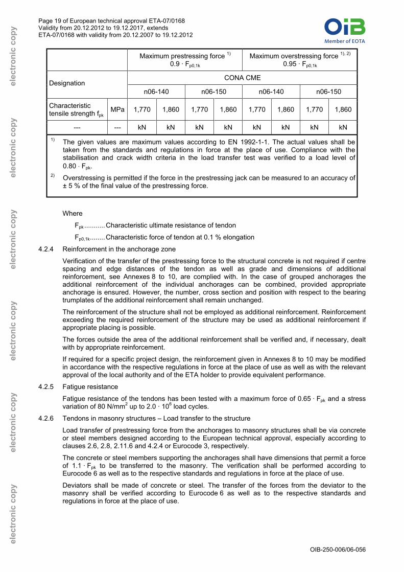
4.2.3 Maximum prestressing force
Table 14 lists the maximum prestressing and overstressing forces.
Table 14: Maximum prestressing and overstressing forces
Maximum prestressing force 1)
0.9 · Fp0,1k
Maximum overstressing force 1), 2)
0.95 · Fp0,1k
CONA CME Designation
n06-140 n06-150 n06-140 n06-150
Characteristic tensile strength fpk
MPa 1,770 1,860 1,770 1,860 1,770 1,860 1,770 1,860
--- --- kN kN kN kN kN kN kN kN
04 767 806 824 864 809 851 870 912
07 1,342 1,411 1,443 1,512 1,416 1,490 1,523 1,596
09 1,725 1,814 1,855 1,944 1,821 1,915 1,958 2,052
12 2,300 2,419 2,473 2,592 2,428 2,554 2,611 2,736
15 2,876 3,024 3,092 3,240 3,035 3,192 3,263 3,420
19 3,642 3,830 3,916 4,104 3,845 4,043 4,133 4,332
22 4,217 4,435 4,534 4,752 4,452 4,682 4,786 5,016
24 4,601 4,838 4,946 5,184 4,856 5,107 5,221 5,472
27 5,176 5,443 5,565 5,832 5,463 5,746 5,874 6,156
n
Number of strands
31 5,943 6,250 6,389 6,696 6,273 6,597 6,744 7,068
Page 19 of European technical approval ETA-07/0168 Validity from 20.12.2012 to 19.12.2017, extends ETA-07/0168 with validity from 20.12.2007 to 19.12.2012
OIB-250-006/06-056
elec
tron
ic c
opy
elec
tron
ic c
opy
elec
tron
ic c
opy
elec
tron
ic c
opy
ele
ctro
nic
copy
e
lect
roni
c co
py
Maximum prestressing force 1)
0.9 · Fp0,1k
Maximum overstressing force 1), 2)
0.95 · Fp0,1k
CONA CME Designation
n06-140 n06-150 n06-140 n06-150
Characteristic tensile strength fpk
MPa 1,770 1,860 1,770 1,860 1,770 1,860 1,770 1,860
--- --- kN kN kN kN kN kN kN kN 1) The given values are maximum values according to EN 1992-1-1. The actual values shall be
taken from the standards and regulations in force at the place of use. Compliance with the stabilisation and crack width criteria in the load transfer test was verified to a load level of 0.80 ⋅ Fpk.
2) Overstressing is permitted if the force in the prestressing jack can be measured to an accuracy of ± 5 % of the final value of the prestressing force.
Where
Fpk ...........Characteristic ultimate resistance of tendon
Fp0,1k........Characteristic force of tendon at 0.1 % elongation
4.2.4 Reinforcement in the anchorage zone
Verification of the transfer of the prestressing force to the structural concrete is not required if centre spacing and edge distances of the tendon as well as grade and dimensions of additional reinforcement, see Annexes 8 to 10, are complied with. In the case of grouped anchorages the additional reinforcement of the individual anchorages can be combined, provided appropriate anchorage is ensured. However, the number, cross section and position with respect to the bearing trumplates of the additional reinforcement shall remain unchanged.
The reinforcement of the structure shall not be employed as additional reinforcement. Reinforcement exceeding the required reinforcement of the structure may be used as additional reinforcement if appropriate placing is possible.
The forces outside the area of the additional reinforcement shall be verified and, if necessary, dealt with by appropriate reinforcement.
If required for a specific project design, the reinforcement given in Annexes 8 to 10 may be modified in accordance with the respective regulations in force at the place of use as well as with the relevant approval of the local authority and of the ETA holder to provide equivalent performance.
4.2.5 Fatigue resistance
Fatigue resistance of the tendons has been tested with a maximum force of 0.65 · Fpk and a stress variation of 80 N/mm2 up to 2.0 · 106 load cycles.
4.2.6 Tendons in masonry structures – Load transfer to the structure
Load transfer of prestressing force from the anchorages to masonry structures shall be via concrete or steel members designed according to the European technical approval, especially according to clauses 2.6, 2.8, 2.11.6 and 4.2.4 or Eurocode 3, respectively.
The concrete or steel members supporting the anchorages shall have dimensions that permit a force of 1.1 · Fpk to be transferred to the masonry. The verification shall be performed according to Eurocode 6 as well as to the respective standards and regulations in force at the place of use.
Deviators shall be made of concrete or steel. The transfer of the forces from the deviator to the masonry shall be verified according to Eurocode 6 as well as to the respective standards and regulations in force at the place of use.

Page 20 of European technical approval ETA-07/0168 Validity from 20.12.2012 to 19.12.2017, extends ETA-07/0168 with validity from 20.12.2007 to 19.12.2012
OIB-250-006/06-056
elec
tron
ic c
opy
elec
tron
ic c
opy
elec
tron
ic c
opy
elec
tron
ic c
opy
ele
ctro
nic
copy
e
lect
roni
c co
py
4.3 Installation
Assembly and installation of tendons may only be carried out by qualified PT specialist companies with the required resources and experience in the use of multi strand external post-tensioning systems, see ETAG 013, Annex D.1 and CWA 14646. The respective standards and regulations in force at the place of use shall be considered. The company’s PT site manager shall have a certificate, stating that she or he has been trained by the ETA holder and that she or he possesses the necessary qualifications and experience with the "BBR VT CONA CME – External Post-tensioning System".
The tendons may be manufactured on site or in the factory (prefabricated tendons).
Bearing trumplate, anchor head and coupler anchor head shall be placed perpendicular to the tendon axis.
At the anchorages and couplers the tendon layout shall provide a straight section over a length as specified in Annex 6.
In the case of the single plane coupler FK the prestressing steel strands shall be provided with markers to be able to check the depth of engagement.
4.4 Stressing operation
With a mean concrete compressive strength in the anchorage zone, fcm 0, complying with the specifications in the Annexes 8 to 10 full prestressing may be applied.
Stressing and, if applicable, wedging shall be carried out using a suitable prestressing jack. The wedging force shall correspond to approximately 25 kN per strand.
After releasing the prestressing force from the prestressing jack, the tendon pulls the strands by the amount of the slip into the anchor head.
Elongation and prestressing forces shall be checked continuously during the stressing operation. The results of the prestressing operation shall be recorded and the measured elongations shall be compared with the prior calculated values.
Information on the prestressing equipment shall be submitted to Österreichisches Institut für Bautechnik. The ETA holder shall save for reference information on the prestressing jacks and the appropriate clearance behind the anchorage.
The safety-at-work and health protection regulations shall be complied with.
4.5 Restressing
Restressing of tendons in combination with release and reuse of wedges is permitted, whereby the wedges shall bite into at least 15 mm of virgin strand surface and no wedge bites shall remain inside the final length of the tendon between anchorages.
For tendons remaining restressable throughout the working life of the structure wax or grease shall be used as filling material. Moreover, a strand protrusion has to remain with a length compatible with the prestressing jack used. The protruding strands shall be provided with an appropriate corrosion protection.
4.6 Filling of ducts
4.6.1 General
The results of the filling operation shall be recorded. The respective standards and regulations in force at the place of use shall be complied with.
4.6.2 Grout
Grout shall be injected through the inlet holes until it escapes from the outlet tubes with the same consistency. To avoid voids in the hardened grout special measures shall be applied for long tendons, tendon paths with distinct high points or inclined tendons. All vents and grouting inlets shall be sealed immediately after grouting.

Page 21 of European technical approval ETA-07/0168 Validity from 20.12.2012 to 19.12.2017, extends ETA-07/0168 with validity from 20.12.2007 to 19.12.2012
OIB-250-006/06-056
elec
tron
ic c
opy
elec
tron
ic c
opy
elec
tron
ic c
opy
elec
tron
ic c
opy
ele
ctro
nic
copy
e
lect
roni
c co
py
The standards to be observed for cement grouting or special grout in ducts are EN 445, EN 446 and EN 447 or the respective standards and regulations in force at the place of use shall be applied for ready mixed grout.
4.6.3 Grease and wax
The specifications in ETAG 013 Annex C.4 and the recommendations of the supplier are relevant for grease and wax.
4.7 Welding
Ducts may be welded.
The helix may be welded to the bearing trumplate to secure its position.
After installation of the tendons further welding may not be carried out on the tendons. In case of welding operations near tendons precautionary measures are required to avoid damage.
Plastic material may be welded after installation of the tendons.
5 Recommendations for the manufacturer
5.1 Recommendations for packing, transport and storage
During transport of prefabricated tendons a minimum diameter of curvature of 1.65 m for tendons up to CONA CME 1206 and 1.80 m for larger tendons shall be observed.
The ETA holder shall safe for reference instructions related to
− Temporary protection of prestressing steels and components in order to prevent corrosion during transportation from the production site to the job site;
− Transportation, storage and handling of the tensile elements and of other components in order to avoid any mechanical, chemical or electrochemical changes;
− Protection of tensile elements and other components from moisture;
− Keeping tensile elements away from areas where welding operations are performed.
5.2 Recommendations on installation
The installation instructions of the ETA holder shall be complied with, see ETAG 013, Annex D.3. The respective standards and regulations in force at the place of use shall be observed. See also Annexes 12 and 13.
5.3 Accompanying information
It is the responsibility of the ETA holder to ensure that all necessary information on design and installation is submitted to those responsible for the design and execution of the works constructed with the "BBR VT CONA CME – External Post-tensioning System".
On behalf of Österreichisches Institut für Bautechnik
The original document is signed by:
Rainer Mikulits
Managing Director

Page 22 of European technical approval ETA-07/0168 Validity from 20.12.2012 to 19.12.2017, extends ETA-07/0168 with validity from 20.12.2007 to 19.12.2012
OIB-250-006/06-056
elec
tron
ic c
opy
elec
tron
ic c
opy
elec
tron
ic c
opy
elec
tron
ic c
opy
ele
ctro
nic
copy
e
lect
roni
c co
py
CONA CME
External Post-tensioning SystemOverview anchorages Annex 1
of European Technical Approval ETA-07/0168

Page 23 of European technical approval ETA-07/0168 Validity from 20.12.2012 to 19.12.2017, extends ETA-07/0168 with validity from 20.12.2007 to 19.12.2012
OIB-250-006/06-056
elec
tron
ic c
opy
elec
tron
ic c
opy
elec
tron
ic c
opy
elec
tron
ic c
opy
ele
ctro
nic
copy
e
lect
roni
c co
py
CONA CME
External Post-tensioning SystemAnchorage parts Annex 2
of European Technical Approval ETA-07/0168
04 07 09 12 15 19 22 24 27 31
Diameter ØA mm 100 130 225 240Height HA mm 50 55 60 65 75 85 95 100 105 110
Diameter ØK mm 185 205 310 340Height HK mm 85 85 90 90 90 95 105 120 125 130
Diameter ØD mm 182 202 306 336Thickness DD mm 3 3 5 5
Dimensions in mm
Cover plate
Number of strandsAnchor head
Coupler head K
255200160
240
3240 380
5
290
3276
390

Page 24 of European technical approval ETA-07/0168 Validity from 20.12.2012 to 19.12.2017, extends ETA-07/0168 with validity from 20.12.2007 to 19.12.2012
OIB-250-006/06-056
elec
tron
ic c
opy
elec
tron
ic c
opy
elec
tron
ic c
opy
elec
tron
ic c
opy
ele
ctro
nic
copy
e
lect
roni
c co
py
CONA CME
External Post-tensioning SystemAnchorage and accessory parts Annex 3
of European Technical Approval ETA-07/0168
04 07 09 12 15 19 22 24 27 31
Diameter ØP mm 130 170 310 325Height HP mm 120 128 206 227
Nominal diameter ØAH mm 100 130 225 240Height HAH mm 55 65 70 80 80 95 100 100 105 115
Minimum Diameter ØH mm 130 167 200 210 256 266 293 309 327 335Length LH mm 180 200 210 230 240 270 270 280 300 320
Diameter ØKS mm 75 103 182 210Thickness DKS mm 5 5 10 10
175
150 250
160
10
Coupler head H
Coupler sleeve H
10
255
145 210
Number of strands
8
200
Wedge retaining plate KS
Bearing trumplate360
195225 280

Page 25 of European technical approval ETA-07/0168 Validity from 20.12.2012 to 19.12.2017, extends ETA-07/0168 with validity from 20.12.2007 to 19.12.2012
OIB-250-006/06-056
elec
tron
ic c
opy
elec
tron
ic c
opy
elec
tron
ic c
opy
elec
tron
ic c
opy
ele
ctro
nic
copy
e
lect
roni
c co
py
CONA CME
External Post-tensioning SystemAnchorage and accessory parts Annex 4
of European Technical Approval ETA-07/0168
04 07 09 12 15 19 22 24 27 31
Diameter ØTA mm 72 88 127 127 153 153 170 191 191 191Length LTA mm 200 328 623 508 694 579 715 871 871 757
Diameter ØTK mm 190 208 245 245 280 280 310 335 380 380Length LTK mm 308 340 428 428 473 473 498 597 734 734
Diameter ØTH mm 140 175 215 225 260 260 295 305 330 330Length LTH mm 110 185 410 420 505 520 565 670 635 645
Diameter ØB mm 165 185 200 200 220 220 240 246 250 250Length LB mm 168 168 168 168 168 168 168 168 168 168
Diameter ØI mm 104 124 140 140 158 158 178 184 188 188Length LI mm 220 220 220 220 220 220 220 220 220 220
Trumpet CME-H
PE-Insert
Tension Ring CME
Number of strands
Trumpet CME-K
Trumpet A

Page 26 of European technical approval ETA-07/0168 Validity from 20.12.2012 to 19.12.2017, extends ETA-07/0168 with validity from 20.12.2007 to 19.12.2012
OIB-250-006/06-056
elec
tron
ic c
opy
elec
tron
ic c
opy
elec
tron
ic c
opy
elec
tron
ic c
opy
ele
ctro
nic
copy
e
lect
roni
c co
py
04 07 09 12 15 19 22 24 27 31Minimum diameter Amin mm 110 140 170 170 210 210 240 250 270 270Minimum height Hmin mm 85 90 90 95 105 115 125 130 140 140Minimum wall thickness Jmin mm 2 2 2 2 2 2 2 2 2 2Minimum cover thickness Fmin mm 5 5 5 5 5 5 5 5 5 5
Number of strands
04 07 09 12 15 19 22 24 27 31Minimum diameter Amin mm 110 140 170 170 210 210 240 250 270 270Minimum wall thickness Jmin mm 3 3 3 3 3 3 3 3 3 3Minimum cover thickness Fmin mm 5 5 5 5 5 5 5 5 5 5
Number of strands
Hmin = depends on the required excess length for the jack
CONA CME
External Post-tensioning SystemCapsExemplary solutions
Annex 5 of European Technical Approval ETA-07/0168

Page 27 of European technical approval ETA-07/0168 Validity from 20.12.2012 to 19.12.2017, extends ETA-07/0168 with validity from 20.12.2007 to 19.12.2012
OIB-250-006/06-056
elec
tron
ic c
opy
elec
tron
ic c
opy
elec
tron
ic c
opy
elec
tron
ic c
opy
ele
ctro
nic
copy
e
lect
roni
c co
py
04 07 09 12 15 19 22 24 27 31Straight length Lmin mm 560 720 1,620 1,650Number of strands
950 1,210
R1 R2 Rmin
04 07 09 12 15 19 22 24 27 31Minimum radii of curvature Rmin m 2.0 2.0 2.5 2.5 2.7 3.0 3.2 3.3 3.5 4.0
.... Additional deviation, e.g. 3°
Number of strands
CONA CME
External Post-tensioning SystemDeviator and Straight length Annex 6
of European Technical Approval ETA-07/0168

Page 28 of European technical approval ETA-07/0168 Validity from 20.12.2012 to 19.12.2017, extends ETA-07/0168 with validity from 20.12.2007 to 19.12.2012
OIB-250-006/06-056
elec
tron
ic c
opy
elec
tron
ic c
opy
elec
tron
ic c
opy
elec
tron
ic c
opy
ele
ctro
nic
copy
e
lect
roni
c co
py
CONA CME
External Post-tensioning SystemConstruction stages Annex 7
of European Technical Approval ETA-07/0168

Page 29 of European technical approval ETA-07/0168 Validity from 20.12.2012 to 19.12.2017, extends ETA-07/0168 with validity from 20.12.2007 to 19.12.2012
OIB-250-006/06-056
elec
tron
ic c
opy
elec
tron
ic c
opy
elec
tron
ic c
opy
elec
tron
ic c
opy
ele
ctro
nic
copy
e
lect
roni
c co
py
mm²mm²
Charact. tensile strength1) fpk MPaCharact. maximum force Fpk kN
kNkN
Min. concrete strength (cube) fcm,0 MPaMin. concrete strength (cyl.) fcm,0 MPa
mmmmmmmm
Distance E mm
mmmm
Distance from anchor plate F mmMin. outer dimensions B mm
Min. centre spacing ac = bc mmMin. edge distance (plus c) ae'=be' mm
Anchor diameter DA mmAnchor length LA mmCoupler FK diameter DFK mmCoupler FK length LFK mmCoupler FH diameter DFH mmCoupler FH length LFH mm
Min. radius Rmin m1.5 Rmin R m
PE-Duct, Rmin da/t mmPE-Duct, 1.5 Rmin da/t mmSteel Duct da/tmin mmc...Concrete cover
1) For strands with a tensile strength of 1,770 MPa see tables 2, 3 and 132) Bar diameter of 14 mm can be replaced by 16 mm3) Exemplary values
63 / 4.7 75 / 4.763.5 / 1.5
90 / 6.7 110 / 6.6
76.1 / 1.5 82.5 / 1.590 / 5.4
3531 35 19 23
320 295
28 31 35 19
30
1065 65
145 135
33
310Center- and edge spacing
175 160110 100 90
Bar diameter2)5 4
270
Spacing 506014 14
290 240 230 220
55 60
4
190 280
60
2018 20 20 2018
Bar diameter2)
Length, approx.PitchNumber of pitches
Additional reinforcementNumber of stirrups 3
0.90 Fp0.1k
0.95 Fp0.1k
HelixOuter diameter
Helix and additional reinforcement - Ribbed reinforcing steel Re 500 MPa
230
19 23
BBR VT CONA CMI
Strand arrangement
StrandCross sectional area
130 1701,710 1,5001,080
Dimensions of ducts3)
- 90 / 8.2
57.0 / 1.5
0704
23 28 34 38 43 23 28 3423 28 35 19
43
225
282 282 337
38
625
1,665 1,435
280
28 3138
170
205185
130435300
1,155850
850
4 4 4
170
3
415
150
50 60 60
12216
12
240
165 150 140
225740
145195 15513085Dimensions of anchorages
Technical data of anchorages
14337182 181 216
15014
18 18
123
1815 15 15
180
18020030 30 30
12
50
4
220
104055
12150
3
230 200 200 180
43
180
3138
14 14 14 14232 232 277 27750 50 60 60
5 5 5 5
28
280 230
60 55
2323
1414
5 514 14
60
14277
143
5
28
6 6 650 50 60
14
412 14 14
1,860
6035
60
230
34
660
330 280
140 / 1501,260 / 1,350
140 / 1501,680 / 1,800
43
260
260 260
414
1414 14 14 14
50 50 50 50332 332 332 382
20 20 20 207 7 7 8
70 65
390 350 320 31035
310405 370 340 325
290
5060 5512 14 167 6 5 6
23
09 12
28 34
3,120 / 3,3482,419 / 2,5922,554 / 2,736
2,340 / 2,511
35
650
282
35 35
16 145
20
2803535 35 35
300
110285 260 250 240
120 115350
1,860
235 215 195
33 33 33 33330
1,040 / 1,116
140 / 150980 / 1,050
1,820 / 1,953
140 / 150560 / 600
1,860 1,860
1,915 / 2,052806 / 864851 / 912
1,411 / 1,5121,490 / 1,596
1,814 / 1,944
Minimum radius of curvature2.0 2.0 2.5 2.73.0 3.0 3.8 4.1
CONA CME
External Post-tensioning SystemDimensions of anchorages, helix and additional reinforcement and spacing
Annex 8 of European Technical Approval ETA-07/0168

Page 30 of European technical approval ETA-07/0168 Validity from 20.12.2012 to 19.12.2017, extends ETA-07/0168 with validity from 20.12.2007 to 19.12.2012
OIB-250-006/06-056
elec
tron
ic c
opy
elec
tron
ic c
opy
elec
tron
ic c
opy
elec
tron
ic c
opy
ele
ctro
nic
copy
e
lect
roni
c co
py
mm²mm²
Charact. tensile strength1) fpk MPaCharact. maximum force Fpk kN
kNkN
Min. concrete strength (cube) fcm,0 MPaMin. concrete strength (cyl.) fcm,0 MPa
mmmmmmmm
Distance E mm
mmmm
Distance from anchor plate F mmMin. outer dimensions B mm
Min. centre spacing ac = bc mmMin. edge distance (plus c) ae'=be' mm
Anchor diameter DA mmAnchor length LA mmCoupler FK diameter DFK mmCoupler FK length LFK mmCoupler FH diameter DFH mmCoupler FH length LFH mm
Min. radius Rmin m1.5 Rmin R m
PE-Duct, Rmin da/t mmPE-Duct, 1.5 Rmin da/t mmSteel Duct da/tmin mmc...Concrete cover
1) For strands with a tensile strength of 1,770 MPa see tables 2, 3 and 132) Bar diameter of 14 mm can be replaced by 16 mm3) Exemplary values
101.6 / 2.0 114.3 / 2.0110 / 5.7 110 / 6.6 125 / 6.0
Dimensions of ducts3)
110 / 8.3 140 / 8.3125 / 7.4
31 3535 19 23 2819 23 28 3123 28 31 3528 31 35 1919 23
375 33014 14
Outer diameter
Number of pitches
Dimensions of anchorages
Center- and edge spacing
Bar diameter2)
Spacing
Additional reinforcementNumber of stirrups
1,825 1,600
BBR VT CONA CMI
Strand arrangement
StrandCross sectional area
0.90 Fp0.1k
0.95 Fp0.1k
Helix
310
2422
280
290855
280
Technical data of anchorages
180
2,0651,970 1,770
1'065325
890
Helix and additional reinforcement - Ribbed reinforcing steel Re 500 MPa
Bar diameter2)
Length, approx.Pitch
740310
2,100 / 2,250 2,660 / 2,850 3,080 / 3,300 3,360 / 3,600140 / 150 140 / 150 140 / 150 140 / 150
23 28 38 4334 38 43 23 4343 23 28 34 3823 28 34 3828 34
280 420 360330 280 330360 330 330 475 420 360 360 360475 430 420 36014 1414 14 14 14 1414 14 14 14
432 432 3821414 14 14 1414 14
432 332 457 457 432 432 382 48250 50
432532 532 482 532482 482 48250 50 50 50 50 5050 50 50 50
9 9 85050 50 50 5050 50
9 7 9.5 9.5 9 9 8 1027 27
911 11 10 1110 10 1027 2727 27 27 27 32 3231 32 32 32
850
382
7 6 5
31 31 31 3127 27
6 5 7 7 87 7 7 814 16
87 7 7 77 7 716 1616 16 16 16 1616 20 20 20
60 65 652016 20 20 2016 16
55 60 65 65 5565 65 65 65
440 400
5580 80 70 6575 70 65
390 370360 350 330 490 420400 560 510 460
455 415 380
440530 480 440 420450 410
365 345 510 465 460 440 420425 410 390 550 435575 525 480 460210200
42 42 42 42
205 195 185175 240 220 210
42
165 245 225220 200500
15 19
2,430310 325
220280 255 230265
42 42 42 42 42 46 46 46
3401,825 2,265
47 47 4746 46 47 47
1,8604,940 / 5,3013,830 / 4,1044,043 / 4,332
1,8605,720 / 6,1384,435 / 4,7524,682 / 5,016
1,8606,240 / 6,6964,838 / 5,1845,107 / 5,472
1,8603,900 / 4,1853,024 / 3,2403,192 / 3,420
Minimum radius of curvature3.0 3.0 3.2 3.34.5 4.5 4.8 5.0
CONA CME
External Post-tensioning SystemDimensions of anchorages, helix and additional reinforcement and spacing
Annex 9 of European Technical Approval ETA-07/0168

Page 31 of European technical approval ETA-07/0168 Validity from 20.12.2012 to 19.12.2017, extends ETA-07/0168 with validity from 20.12.2007 to 19.12.2012
OIB-250-006/06-056
elec
tron
ic c
opy
elec
tron
ic c
opy
elec
tron
ic c
opy
elec
tron
ic c
opy
ele
ctro
nic
copy
e
lect
roni
c co
py
mm²mm²
Charact. tensile strength1) fpk MPaCharact. maximum force Fpk kN
kNkN
Min. concrete strength (cube) fcm,0 MPaMin. concrete strength (cyl.) fcm,0 MPa
mmmmmmmm
Distance E mm
mmmm
Distance from anchor plate F mmMin. outer dimensions B mm
Min. centre spacing ac = bc mmMin. edge distance (plus c) ae'=be' mm
Anchor diameter DA mmAnchor length LA mmCoupler FK diameter DFK mmCoupler FK length LFK mmCoupler FH diameter DFH mmCoupler FH length LFH mm
Min. radius Rmin m1.5 Rmin R m
PE-Duct, Rmin da/t mmPE-Duct, 1.5 Rmin da/t mmSteel Duct da/tmin mmc...Concrete cover
1) For strands with a tensile strength of 1,770 MPa see tables 2, 3 and 132) Bar diameter of 14 mm can be replaced by 16 mm3) Exemplary values
127.0 / 2.5
140 / 8.3 160 / 9.5Dimensions of ducts3)
50
245295 270
50 50 50
360
235520 495
220 240250315 290 265
50 5050 50 50 50500 480
610 555 505 485 460 650 595 545
65 60
590 540 490 470 440 630 580 530
20 2080 80 75 70 60 85 75 70
8 820 20 20 20 20 20 20 20
3512 9
35 35 35 35 35 35 35 35
40 5011 11 11 11 9 11 11 12
467 43250 50 50 40 50 50 50 50
14 14532 532 532 427 432 532 532 582
430 43014 14 14 14 14 14 14 14520 475 430 420 360 560 520 475
28 34 38 43
3,780 / 4,050 4,340 / 4,650
Technical data of anchorages
1,090
23 28 34 38 43 23
27 31
140 / 150 140 / 150
970390
3602,500 2,285
2,470 2,245
140 / 6.7 140 / 8.3
BBR VT CONA CMI
Strand arrangement
StrandCross sectional area
0.90 Fp0.1k
0.95 Fp0.1k
HelixOuter diameter
Helix and additional reinforcement - Ribbed reinforcing steel Re 500 MPa
3519 23 28 31
Bar diameter2)
Length, approx.PitchNumber of pitches
35
8 7 7 7Additional reinforcementNumber of stirrups
Dimensions of anchorages
Center- and edge spacing
Bar diameter2)
Spacing
8 8 8 8
19 23 28 31 35
1,8608,060 / 8,6496,250 / 6,6966,597 / 7,068
1,8607,020 / 7,5335,443 / 5,8325,746 / 6,156
Minimum radius of curvature3.5 4.05.3 6.0
CONA CME
External Post-tensioning SystemDimensions of anchorages, helix and additional reinforcement and spacing
Annex 10 of European Technical Approval ETA-07/0168

Page 32 of European technical approval ETA-07/0168 Validity from 20.12.2012 to 19.12.2017, extends ETA-07/0168 with validity from 20.12.2007 to 19.12.2012
OIB-250-006/06-056
elec
tron
ic c
opy
elec
tron
ic c
opy
elec
tron
ic c
opy
elec
tron
ic c
opy
ele
ctro
nic
copy
e
lect
roni
c co
py
CONA CME
External Post-tensioning SystemModification of Centre and Edge distance Annex 11
of European Technical Approval ETA-07/0168
ac = bc ac < bc
ae = be ae < be
Modification of Center and Edge distances must be in accordance with clause 2.6:
ac 0.85 · ac and Helix, outside diameter 1)
bc
c
c
bA
Ac = ac · bc ac · bc
Corresponding edge distances
ae =2ac - 10 + c and be =
2bc -10 + c
c...Concrete cover
1) The outer dimensions of the additional reinforcement shall be adjusted accordingly. Furthermodifications of reinforcement have to be in accordance with clause 4.2.4.

Page 33 of European technical approval ETA-07/0168 Validity from 20.12.2012 to 19.12.2017, extends ETA-07/0168 with validity from 20.12.2007 to 19.12.2012
OIB-250-006/06-056
elec
tron
ic c
opy
elec
tron
ic c
opy
elec
tron
ic c
opy
elec
tron
ic c
opy
ele
ctro
nic
copy
e
lect
roni
c co
py
Installation
1 Preparatory work The components of the prestressing kit shall be stored in such a way as to avoid any damage or corrosion.
2 Anchorage recesses Adequate clearance to accommodate and to use the prestressing jack shall be ensured, see also clauses 2.1.5 and 4.2.2.
3 Fixing the bearing trumplates Four holes are provided to fix the bearing trumplates to the formwork. The trumpet is screwed into the bearing trumplate. The helix is either welded to the bearing trumplate by means of radial bars, see also clause 4.7, or positioned by fixing it to the existing reinforcement. The trumpet and a piece of the duct are connected in a waterproof way. In the final position the duct shall protrude at least 100 mm out of the formwork.
4 Installation of deviators For accurate installation it is recommended to use a guide wire or something equivalent between successive deviators for pre-adjustment. The deviator shall be properly connected to the formwork and the reinforcement mesh to avoid any movement during concreting. If required, recess units shall be inserted in the deviator to avoid deformations. The minimum radii of curvature shall comply with clause 2.3.
5 Placing of ducts The ducts are placed on supports with a spacing of 2 m to 4 m by taking into account the increase of weight due to the tensile elements. The ducts have to be jointed in a waterproof way, see also clause 2.3. In the case of plastic ducts at least one telescopic joint shall be installed do adjust the length of the duct to the tendon. This opening will be jointed after stressing.
6 Installation of tensile elements (prestressing steel) The prestressing steel is pushed or pulled into the duct.
7 Installation of inaccessible fixed anchorages After passing the strands through the anchor head, they are anchored individually in the cones by means of ring wedges. After assembling, the wedges are secured in accordance with clause 2.1.3.1.
8 Installation of fixed coupler anchor block 2.BA The function of the fixed coupler is to connect two tendons, whereby the first tendon is stressed before the second tendon is installed and stressed. The coupling is achieved by pushing the strands into the already tensioned coupler anchor head K, 2.BA, outer pitch circle, whereby the strands have to be marked to check the correct depth of penetration. The coupler anchor head H, 2.BA, is assembled with ring wedges which are secured in accordance with clause 2.1.3.1. It is connected to the already tensioned coupler anchor head H, 1.BA, by means of a threaded coupler sleeve.
9 Assembly of anchor block/coupler anchor 1.BA After passing the strands through the anchor head, they are anchored individually in the cones by means of ring wedges. The same applies for the coupler anchor head in the case of fixed couplers in the first construction stage.
CONA CME
External Post-tensioning SystemDescription of installation Annex 12
of European Technical Approval ETA-07/0168

Page 34 of European technical approval ETA-07/0168 Validity from 20.12.2012 to 19.12.2017, extends ETA-07/0168 with validity from 20.12.2007 to 19.12.2012
OIB-250-006/06-056
elec
tron
ic c
opy
elec
tron
ic c
opy
elec
tron
ic c
opy
elec
tron
ic c
opy
ele
ctro
nic
copy
e
lect
roni
c co
py
10 Stressing At the time of stressing the mean concrete compressive strength shall be at least according to Table 9 and the provisions of clause 2.8. Stressing and possible wedging has to be carried out with a suitable prestressing jack in accordance with clause 4.4. The elongation of the tendon and the prestressing forces shall be checked and recorded systematically during the stressing operation. Restressing the tendons is allowed in accordance with clause 4.5.
11 Filling the tendons Grout shall be injected through the inlet holes until it escapes from the outlet tubes with the same consistency. All vents and grouting inlets shall be sealed immediately after grouting, see also clause 4.6. Grease and wax has to be injected in accordance with ETAG 013 and the recommendations of the supplier.
More detailed information on installation can be obtained from the ETA holder.
CONA CME
External Post-tensioning SystemDescription of installation Annex 13
of European Technical Approval ETA-07/0168

Page 35 of European technical approval ETA-07/0168 Validity from 20.12.2012 to 19.12.2017, extends ETA-07/0168 with validity from 20.12.2007 to 19.12.2012
OIB-250-006/06-056
elec
tron
ic c
opy
elec
tron
ic c
opy
elec
tron
ic c
opy
elec
tron
ic c
opy
ele
ctro
nic
copy
e
lect
roni
c co
py
Grease specification
Characteristics Test method, Standard Acceptance criteria
Cone penetration, 60 strokes (1/10mm) ISO 2137 250 - 300
Dropping point ISO 2176 ≥ 150 °C
Oil separation at 40 °C DIN 51817 At 72 hours ≤ 2.5 % At 7 days ≤ 4.5 %
Oxidation stability DIN 51808 100 hours at 100 °C ≤ 0.06 MPa 1000 hours at 100 °C ≤ 0.2 MPa
Corrosion protection 168 hours at 35 °C 168 hours at 35 °C
NF X41-002 (salt spray) 1)
NF X41-002 (distilled water spray) 1)
PassNo corrosion
Corrosion test DIN 51802 Grade 0
Content of aggressive elements Cl-, S2-, NO3
-
SO42-
NF M07-023 2)
NF M07-023 2)≤ 50 ppm (0.005%) ≤ 100 ppm (0.010%)
Notes1) Test sample consists of a structural steel plate Fe 510 with a surface roughness comparable to
prestressing wire and strand. The plate is covered with a layer of grease of a maximum thickness corresponding of the declared mass of filling material per linear meter of monostrand divided by the nominal strand surface per linear meter (based on nominal strand diameter).
2) Applied accordingly to grease.
Wax specification
Characteristics Test method, Standard Acceptance criteria
Congealing point NF T60-128 ≥ 65 °C
Penetration (1/10mm) at -20 °C NF T60-119 No cracking
Bleeding at 40 °C BS 2000:part 121 (1982) modified
≤ 0.5 %
Resistance to oxidation 100 hours at 100 °C
ASTM D942.70 ≤ 0.03 MPa
Copper-strip corrosion 100 hours at 100 °C
ISO 2160 Class 1a
Corrosion protection 168 hours at 35 °C 168 hours at 35 °C
NF X41-002 (salt spray) 1)
NF X41-002 (distilled water spray) 1)
PassNo corrosion
Content of aggressive elements Cl-, S2-, NO3
-
SO42-
NF M07-023 NF M07-023
≤ 50 ppm (0.005%) ≤ 100 ppm (0.010%)
Note1) Test sample consists of a structural steel plate Fe 510 with a surface roughness comparable to
prestressing wire and strand. The plate is covered with a layer of grease of a maximum thickness corresponding of the declared mass of filling material per linear meter of monostrand divided by the nominal strand surface per linear meter (based on nominal strand diameter).
CONA CME
External Post-tensioning SystemSpecifications Annex 14
of European Technical Approval ETA-07/0168

Page 36 of European technical approval ETA-07/0168 Validity from 20.12.2012 to 19.12.2017, extends ETA-07/0168 with validity from 20.12.2007 to 19.12.2012
OIB-250-006/06-056
elec
tron
ic c
opy
elec
tron
ic c
opy
elec
tron
ic c
opy
elec
tron
ic c
opy
ele
ctro
nic
copy
e
lect
roni
c co
py
Seven-wire strands according to prEN 10138-3 a)
Y 1770S7 Y1860S7 Y1770S7 Y1860S7Tensile strength Rm MPa 1,770 1,860 1,770 1,860
Diameter d mm 15.3 15.3 15.7 15.7
Nominal cross-sectional area Ap mm2 140 140 150 150
Nominal mass per metre m kg/m
Characteristic value ofmaximum force
Fpk kN 248 260 266 279
Maximum value of maximumforce
Fm,max kN 285 299 306 321
Characteristic value of 0,1% proof force
Fp0,1 kN 213 224 229 240
Minimum elongation at max.force, L0 500 mm Agt %
Modulus of elasticity Ep MPaa) Suitable strands according to standards and regulations in force at the place of use may also be used.
Steel name
Permitted deviation from nominalmass
195,000b)
% ± 2
3.5
1.093
b) Standard value
Strand
1.172
CONA CME
External Post-tensioning SystemSpecifications Annex 15
of European Technical Approval ETA-07/0168

Page 37 of European technical approval ETA-07/0168 Validity from 20.12.2012 to 19.12.2017, extends ETA-07/0168 with validity from 20.12.2007 to 19.12.2012
OIB-250-006/06-056
elec
tron
ic c
opy
elec
tron
ic c
opy
elec
tron
ic c
opy
elec
tron
ic c
opy
ele
ctro
nic
copy
e
lect
roni
c co
py
Reference documents
Guideline for European technical approval ETAG 013 (06.2002) Guideline for European technical approval of Post-Tensioning Kits for
Prestressing of Structures
Standards EN 206-1 (12.2000), A1 (07.2004), A2 (06. 2005) Concrete - Part 1: Specification, performance, production and
conformity EN 445 (10.2007) Grout for prestressing tendons - Test methods EN 446 (10.2007) Grout for prestressing tendons - Grouting procedures EN 447 (10.2007) Grout for prestressing tendons - Specification for common grout EN 1561 (10.2011) Founding - Grey cast irons EN 1563 (12.2011) Founding - Spheroidal graphite cast irons EN 1992-1-1 (12.2004), AC (01.2008), AC (11.2010) Eurocode 2: Design of concrete structures - Part 1-1:
General rules and rules for buildings EN 10025-2 (11.2004), AC (06.2005) Hot rolled products of structural steels - Part 2: Technical delivery
conditions for non-alloy structural steels EN 10083-1 (08.2006) Steels for quenching and tempering - Part 1: General technical delivery
conditionsEN 10083-2 (08.2006) Steels for quenching and tempering - Part 2: Technical delivery conditions
for non alloy steels EN 10084 (04.2008) Case hardening steels - Technical delivery conditions EN 10204 (10.2004) Metallic products - Types of inspection documents EN 10210-1 (04.2006) Hot finished structural hollow sections of non-alloy and fine grain structural
steels – Part 1: technical delivery requirements EN 10216-1 (05.2002), A1 (03.2004) Seamless steel tubes for pressure purposes - Technical delivery
conditions - Part 1: Non-alloy steel tubes with specified room temperature properties
EN 10217-1 (05.2002), A1 (01.2005) Welded steel tubes for pressure purposes - Technical delivery conditions - Part 1: Non-alloy steel tubes with specified room temperature properties
EN 10219-1 (04.2006) Cold formed welded structural hollow sections of non-alloy and fine grain steels - Part 1: Technical delivery conditions
EN 10255 (08.2004), A1 (04.2007) Non-alloy steel tubes suitable for welding and threading - Technical delivery conditions
EN 10270-1 (10.2011) Steel wire for mechanical springs - Part 1: Patented cold drawn unalloyed spring steel wire
EN 10277-2 (03.2008) Bright steel products - Technical delivery conditions - Part 2: Steels for general engineering purposes
EN 10305-5 (01.2010) Steel tubes for precision applications - Technical delivery conditions - Part 5: Welded cold sized square and rectangular tubes
EN 12201 (09.2011) Plastics piping systems for water supply, and for drainage and sewerage under pressure - Polyethylene (PE)
EN ISO 1872-1 (05.1999) Plastics - Polyethylene (PE) moulding and extrusion materials - Part 1: Designation system and basis for specifications (ISO 1872-1:1993)
ENV 1992-1-5 (10.1994) Eurocode 2 - Design of concrete structures - Part 1-5: General rules - Structures with unbonded and external prestressing tendons
prEN 10138-3 (04.2005) Prestressing steels - Part 3: Strands
CWA 14646 (01.2003) Requirements for the installation of post-tensioning kits for prestressing of structures and qualification of the specialist company and its personnel
CONA CME
External Post-tensioning SystemReference Documents Annex 16
of European Technical Approval ETA-07/0168


BBR VT International LtdTechnical Headquarters and Business Development CentreSwitzerland
Cop
yrig
ht B
BR
VT
Inte
rnat
iona
l 06.
2016
KB Vorspann-Technik GmbH Weitwörth 25 5151 Nussdorf a. H. Austria
Tel +43 6272 40790 Fax +43 6272 40790 11
www.kb-vt.com [email protected]
KB Vorspann-Technik GmbH Bahnhofstrasse 108 82166 Gräfelfing Germany
Tel +49 89 724 49 69 0 Fax +49 89 724 49 69 12
www.kb-vt.com [email protected]