external tank program legacy of success ken welzyn – … · aiaa technical paper – external...
TRANSCRIPT

1 American Institute of Aeronautics and Astronautics
AIAA Technical Paper – External Tank Program – Legacy of Success
Jeffery C. Pilet0F
1, Dawn Diecidue-Conners1F
2, Michelle Worden2F
3, Michelle Guillot3F
4 Lockheed Martin Space Systems Company, New Orleans, LA, 70129
and
Kenneth Welzyn4F
5 NASA, Marshall Space Flight Center, Huntsville, AL 35812
The largest single element of Space Shuttle is the External Tank (ET), which serves as the structural backbone of the vehicle during ascent and provides liquid propellants to the Orbiter’s three Main Engines. The ET absorbs most of the seven million pounds of thrust exerted by the Solid Rocket Boosters and Main Engines. The design evolved through several block changes, reducing weight each time. Because the tank flies to orbital velocity with the Space Shuttle Orbiter, minimization of weight is mandatory, to maximize payload performance. The initial configuration, the standard weight tank, weighed 76,000 pounds and was an aluminum 2219 structure. The light weight tank weighed 66,000 pounds and flew 86 missions. The super light weight tank weighed 58,500 pounds and was primarily an aluminum-lithium structure. The final configuration and low weight enabled system level performance sufficient for assembly of the International Space Station in a high inclination orbit, vital for international cooperation. Another significant challenge was the minimization of ice formation on the cryogenic tanks. This was essential due to the system configuration and the choice of ceramic thermal protection system materials on the Orbiter. Ice would have been a major debris hazard. Spray on foam insulation materials served multiple functions including thermal insulation, conditioning of cryogenic propellants, and thermal protection for the tank structure during ascent and entry. The tank is large, and unique manufacturing facilities, tooling, and handling, and transportation operations were developed. Weld processes and tooling evolved with the design as it matured through several block changes. Non Destructive Evaluation methods were used to assure integrity of welds and thermal protection system materials. The aluminum-lithium alloy was used near the end of the program and weld processes and weld repair techniques had to be refined. Development and implementation of friction stir welding was a substantial technology development incorporated during the Program. Automated thermal protection system application processes were developed for the majority of the tank surface. Material obsolescence was an issue throughout the multi-decade program. Process controls were implemented to assure cleanliness in the production environment, to control contaminants, and to preclude corrosion. Each tank was accepted via rigorous inspections, including non-destructive evaluation techniques, proof testing, and all systems testing. In the post STS-107 era, the project focused on ascent debris risk reduction. This was accomplished via stringent process controls, post flight assessment using substantially improved imagery, and selective redesigns. These efforts were supported with a number of test programs to simulate combined environments. The debris risk was reduced by two orders of magnitude. During this time a major natural disaster was overcome when hurricane Katrina damaged the manufacturing facility. Numerous lessons from these efforts, the manufacturing and material processing issues, the key design features, and evolution of the design will be discussed.
1 Chief Engineer, External Tank, Lockheed Martin Space Systems Company, Michoud Assembly Facility 2 Manager, Requirements Verification, Lockheed Martin Space Systems Company, Michoud Assembly Facility 3 Staff Weld Engineer, Lockheed Martin Space Systems Company, Michoud Assembly Facility 4 Manager, Thermal Analysis, Lockheed Martin Space Systems Company, Michoud Assembly Facility 5 Chief Engineer, External Tank, NASA/MSFC/EE02
https://ntrs.nasa.gov/search.jsp?R=20120001570 2018-05-29T18:59:31+00:00Z

2 American Institute of Aeronautics and Astronautics
Nomenclature ALTA Aluminum lithium test article Al-Li Aluminum lithium ET External Tank F/L Feed Line FSW Friction stir weld gpm Gallons per minute GTAW Gas tungsten arc welding GVTA Ground vibration test article HDF High density fluid HWT Heavy weight tank ISS International Space Station LH2 Liquid hydrogen LO2 Liquid oxygen LWT Light weight tank M&P Materials and Processes MAF Michoud Assembly Facility MPTA Main propulsion test article MSFC Marshall Space Flight Center NASA National Aeronautics and Space Administration NCFI North Carolina Foam Industries NPSP Net positive suction pressure RTF Return to Flight SLA Super light ablator SLS Space Launch System SLWT Super light weight tank SOFI Spray on foam insulation SPAW Soft plasma arc welding SRB Solid rocket booster SSME Space Shuttle Main Engine STA Structural test article STS Space Transportation System SWT Standard weight tank TIG Tungsten inert gas TPS Thermal protection system VPPA Variable polarity plasma arc WSA Weld sub assembly

3 American Institute of Aeronautics and Astronautics
I. Introduction
HE Space Shuttle’s External Tank (ET) is a highly evolved and optimized system that serves as the structural backbone of the Space Transportation
System (STS) launch vehicle (Figure 1). Several major design changes to the ET have occurred since the first flight of the Shuttle 30 years ago, with emphasis on improving overall system payload performance, reducing manufacturing flow time, and improving design robustness. Through the process of evolving the ET design, many challenges were experienced and ultimately overcome by a very proud, resilient, and cohesive team consisting of National Aeronautic and Space Administration (NASA) and Lockheed Martin engineers from NASA’s Marshall Space Flight Center (MSFC) in Huntsville AL and the Michoud Assembly Facility (MAF) in New Orleans, LA. The purpose of this paper is to provide an overview of some of the more challenging issues and resulting lessons learned to potentially benefit the follow-on Space Launch System (SLS) core stage booster program. The paper provides an overview of the ET design, a discussion of the major structural design evolutions, innovative welding techniques, the debris minimization efforts that occurred after the Columbia accident, and several key technical challenges that were recently experienced and overcome.
II. Design Overview
The ET contains and delivers propellants for the Orbiter's three main engines during the launch phase and serves as the structural backbone for the Orbiter and two Solid Rocket Boosters (SRBs) to make up the Space Shuttle flight vehicle. The liquid oxygen (LO2) tank volume is 19,463 cubic feet and contains approximately 1,385,000 pounds of oxidizer. The liquid hydrogen (LH2) tank volume is 52,371 cubic feet and contains approximately 231,000 pounds of propellant fuel. These volumes include a 3% ullage provision.
The ET structure must accommodate complex load paths in that the SRB thrust loads will be induced forward at the Intertank while the Orbiter thrust loads will be induced at aft ET/Orbiter attachment points. The SRB thrust will be as high as 2.9 million pounds each at sea level and the Orbiter's three main engines will develop as much as 375,000 pounds thrust each at sea level.
Three primary structures make up the ET; a LO2 tank, an Intertank, and a LH2 tank (Figure 2). Since the ET is the only expendable element of the Space Shuttle, the design philosophy has been to minimize active or moving parts. All power, pressure, and purges are received from either the Orbiter or ground facility. The only active components on the ET are the vent/relief valves. All operational instrumentation is hardwired to the Orbiter. The separation is pyrotechnically actuated. Slosh baffles are mounted in the LO2 tank and the LH2 tank has a vortex baffle to dampen fluid motion and minimize liquid residuals. Both tanks contain liquid level sensors for propellant loading control.
T
Figure 1: STS on Pad
Figure 2: ET Primary Structures

4 American Institute of Aeronautics and Astronautics
Both tanks are constructed of aluminum alloy skins with support or stability frames as required, and their skins are welded to provide reliable sealed joints. The sidewalls and end domes require the largest available width of plate stock. The Intertank structure utilizes skin stringers with stabilizing frames. The primary structural attachment to the Orbiter consists of one forward and two aft connections, and the primary structural attachment to each of the two SRBs also consists of one forward and three aft connections. Structural design of the ET is complicated by the fact that interactive load effects emanating from internal propellants and pressures, and external aerodynamic pressures and heating must be accommodated. Additional loads associated with the attached Orbiter and SRBs must also be provided for structurally.
The ET contains all the LH2 and LO2 for the Orbiter's main engines. The propulsion system serves the primary function of delivering this oxidizer and fuel to and from the propellant tanks and Orbiter interface through 17 inch feedline disconnects. Delivery rates to the Orbiter are typically 45,300 gpm for LH2 and 17,000 gpm for LO2.
The propulsion subsystems designed to accomplish this and other required functions are the LO2 feedline subsystem, LO2 and LH2 pressurization and vent/relief subsystems, and the Intertank and tank environmental control subsystems.
All controls and valves for the main propulsion system's operation - except for the LO2 and LH2 vent/relief valves, check valves in the helium inject line, and those valves integral to the interface disconnects - are located in the Orbiter and during prelaunch operations in the Facility. Propellants are loaded (and off-loaded, if required) through the Orbiter. Loading rates can reach 12,000 gpm for the LH2 and up to 5,000 gpm for LO2.
The electrical system provides instrumentation sensors, heaters, lightning protection, and associated cabling. All electrical power is derived from the Orbiter except for heater power which is provided by the ground facilities.
The ET thermal protection system (TPS) is applied to the external surfaces to maintain the cryogenic propellant quality, to protect the structure from ascent and plume heating, and to minimize ice/frost formation. TPS is applied to 16,750 square feet and accounts for approximately 4,000 pounds of the ET weight. Three primary materials are used on the ET. BX-265, NCFI 24-57, and NCFI 24-124 Spray-On Foam Insulation (SOFI) are the primary cryogenic insulations; and SLA 561 is the primary ablator. Minor quantities of other foams are used for closeouts and MA25S ablator is used for a highly heated local areas.
III. Design and Manufacturing Evolution
UET Structural Evolution to Support Program Requirements
The ET has experienced several major design changes to meet the various mission requirements and mission phases of the STS. The robust, initial design often referred to as the Standard Weight Tank (SWT) or Heavy Weight Tank (HWT) design has served as the foundation for a ‘building block’ approach used to develop lighter weight, more producible designs. The two (2) major redesigns are commonly referred to as the Lightweight Tank (LWT) and the Super Lightweight Tank (SLWT). In addition to the performance benefits derived from the LWT and SLWT tanks, the SLWT design was further evolved to mitigate producibility issues that resulted from configuration and material changes (mainly fusion welding of aluminum-lithium (Al-Li) alloy). The producibility enhancements were staged incrementally starting with ET-122 to minimize performance impacts. The final phase of the producibility enhancements was first implemented on ET-134 (STS-130) and flown on the final tank, ET-138 (STS-135).
Structural verification of the baseline SWT included three major test programs that would serve as the foundation for future designs:
1. Instrumented Structural Test Article (STA) 2. Ground Vibration Test Article (GVTA) 3. Main Propulsion Test Article (MPTA)
These tests provided the data that enabled weight reduction through elimination of components and materials, resizing of material thicknesses, and substitution of materials for lighter weight materials. The initial design

5 American Institute of Aeronautics and Astronautics
leveraged the analytical models and test data obtained from the Saturn SI-C and Titan programs, but as test data became available from ET verification test programs, as well as further design environment refinements, some conservatisms were incrementally reduced allowing for optimized structural margins of safety.
1981 – 1983 1983 – 1998 1998 - 2011 Standard Weight Tank (SWT) Light Weight Tank (LWT) Super Light Weight Tank (SLWT)
~77,000 lb ~66,000 lb ~58,500 lb 6 flown 86 flown 43 flown
First flown: STS-1, April 12, 1981 First flown: STS-6, April 4, 1983 First flown: STS-91, June 2, 1998 Additional performance required for
Galileo mission Additional performance required for
57 degree inclination missions for International Space Station (ISS)
Table 1: ET Design and Weight Evolution
UET Structural Design Drivers
The ET is the central, integrating element of the Shuttle system, subject to thrust loads from SRBs and SSMEs in flight, and loads from the Orbiter (weight, winds, etc) on the launch pad. The ET also has to allow for flexure due to cryogenics and ullage pressures. ET attachments for the Orbiter and SRBs, and supports for other required pipes and cable trays introduce point loads with bending stresses, in addition to the pure membrane stresses of a pressure vessel, and result in stress discontinuities.
Since the ET reaches near orbital speed (~16 ft/sec less than orbital speed) ET weight translates directly into payload weight, so a lightweight efficient design is essential. This leads to design optimization and strict weight control for all tank systems. The key design features and requirements of the ET are:
1. An Intertank (or interstage) is required to join the LO2 and LH2 tanks due to thrust transfer requirements from the two SRBs and design simplicity.
2. Vehicle controllability dictates that that LO2 tank is located at the front of the ET due to the weight of the oxidizer.
3. The LO2 tank forward end is capped by an ogive shape (formed by an arc of a circle, of 612 inch radius, rotated about the longitudinal (or X) axis of the tank) for aerodynamic considerations.
4. Elliptical domes cap off the aft of LO2 tank, and both ends of the LH2 tank. 5. Slosh baffles for LO2 are required as determined by guidance, navigation and control analysis to damp out
any destabilizing oscillations of the LO2. 6. Tank volume supplies fuel to the SSMEs at the required inlet net positive suction pressure (NPSP).
The LO2 tank and the LH2 tank rate of delivery was developed using trajectory simulations that considered the properties of the fuels at cryogenic temperatures. The LH2 fuel is fed to the engines at the rate of 45,283 gpm at a temp of -423°F and the LO2 oxidizer at 16,800 gpm at a temp of -297ºF. The NPSP requirements were used to define the tank ullage pressures and subsequently the tank cylinder wall thickness. The dome and ogive wall thicknesses were sized to prevent any radial deformation mismatch, and to preclude any bending stresses at cylinder/end closure interfaces.
Light Weight Tank (LWT) Design Changes to Improve Performance
Design development of the LWT was initiated prior to the first flight of the Space Shuttle. A lighter weight tank was required to support manifest planning of the Galileo spacecraft in the early 1980s. The light weight tank design (Figure 3) was achieved through a series of modifications that were enabled through test calibrated model refinement, operational enhancements and a method to tailor margins. These enhancements provided the foundation to resize structural membranes, elimination of hardware elements (e.g. thermal protection system, development flight instrumentation, the anti-geysering line), and material substitutions that were critical to achieving the desired weight reduction of 6000 lbs. Verification of the LWT design was accomplished primarily with STA-based analysis

6 American Institute of Aeronautics and Astronautics
and proof test of the first production article. Approximately 5,380 lbs were reduced through the structural redesign for the LWT.
1. LO2 Tank
The net weight reduction for the LO2 tank was negligible (-5 lbs) due to the increase the LO2 forward ogive membranes. The forward ogive structural redesign increased the membranes to preclude buckling during the cryo loading operations. For the SWT, operational constraints were levied that required a 1.7 psig backpressure during the cryo loading operations to preclude buckling. Weight savings was achieved by reducing the forward ogive bulkhead and cover plate web thickness, decreasing the aft ogive, barrel panel, and aft dome membrane thickness and reducing the dome and dome weld land membranes.
2. Intertank
High margins on the Intertank structure were the primary reason for the weight reduction in the Intertank structure. The Intertank skin / stringer panels, main frame, the SRB thrust beam frame (or crossbeam), and the intermediate frames were resized to maintain the factor of safety with sufficient margin. In addition to these changes, additional weight savings was achieved through resizing other components such as thrust fittings, internal attachment, frame stabilizers and splice plates. The net savings for the Intertank was ~1,200 lbs. These changes were verified by test-correlated analysis.
3. LH2 Tank
The most significant weight reduction was achieved through redesign of the LH2 tank resulting in a weight savings of ~3,285 lbs. The major credit for the savings can be attributed to elimination of stabilizing frames (5) and barrel stringers, resizing barrel panel membranes, and resizing inner and outer chord and web thickness. The optimized design was verified by STA-correlated analysis, proof test, and a limit load test.
Figure 3: Structural Changes for LWT

7 American Institute of Aeronautics and Astronautics
4. Interface Hardware
In addition to the tank structural changes, the interface hardware was redesigned to achieve additional weight savings. The interface hardware is where the ET attaches to the other shuttle elements (Orbiter and SRBs). The attach points are: Forward ET/Orbiter bipod attachment; Forward ET/SRB thrust attachments (2); Aft ET/Orbiter attachments (2); Aft ET/SRB attachments (2 upper and 2 lower). The loads at the interfaces were revised by the integration contractor enabling structural hardware resizing and material substitution for some hardware. The total weight savings of 823 lbs was primarily achieved through redesign of the thrust struts and end fittings, the aft crossbeam, and the aft ET/Orbiter attachment ball fittings. Although not considered structural changes, significant weight savings were also achieved by deletion of the antigeysering lines, development flight instrumentation, and the white paint covering the TPS.
Super Light Weight Tank (SLWT) Design Changes to Improve Performance
Design and certification of the SLWT was a critical turning point in the Space Shuttle Program’s ability to support construction of the International Space Station (ISS). A target of 7,500 lbm reduction was required to achieve the 51.6° orbital inclination with an ISS payload. Several challenges were identified early in the program:
• Aggressive schedule to support ISS program • Parallel development of a lightweight Al-Li material, and associated manufacturing processes, and design • Structural verification program constrained by funding and schedule • Dedicated full-scale, cryogenic structural tests not planned • Significant production impacts caused by Al-Li alloy weld-related rework • Design and production development parallel with production of traditional LWTs
The SLWT used Al-Li alloys in place of traditional Al 2219 at several locations on the LO2 and LH2 Tanks. Aluminum-lithium (Al-Li) alloys offer the benefit of improved yield strength, stiffness, and reduced density. The use of this state of the art alloy required an extensive material test program to determine material allowables, weld land sizes, and manufacturing processes / requirements. The most significant configuration change for the SLWT was the use of Al-Li 2195 orthogrid barrel panels in place of the Al 2219 T-stiffened panels used for SWT and LWT configurations. The use of orthogrid wall construction for the LH2 tank required development of new manufacturing process for machining, forming, and welding of barrel assemblies.
Figure 4: Structural Changes for SLWT

8 American Institute of Aeronautics and Astronautics
To address the design and manufacturing challenges, the ET Project had to engage industry experts, leverage all available resources and existing data bases, develop innovative designs to optimize performance, develop innovative material and acceptance programs, and evolve the design to mitigate production issues. A special Structural Verification Team was convened to resolve the challenges associated with design certification of the SLWT. The team established a verification approach that was crucial to the success of the SLWT within the budget and schedule constraints levied by NASA.
Verification Groundrules and Philosophy • Verification is demonstrated by either test or flight history of the ET • Test verify the structural integrity of each element • Test demonstrate that each element will withstand ultimate load • No test is required if a more critical and similar element has been tested • All test articles require production material, processes, and tooling • Deviations may be acceptable based on case by case rationale • Test completion is prerequisite to flight or critical design condition
The result was an innovative, multi-faceted verification program including verification data obtained from: 1) Existing data base; 2) Component tests; 3) Independent analysis, and 4) aluminum-lithium test article (ALTA).
Figure 6: SLWT ET Structural Verification Approach
Figure 5: Comparison of SWT / LWT to SLWT LH2 Tank Barrels

9 American Institute of Aeronautics and Astronautics
1) UExisting Data BaseU – The team utilized a wealth of test and flight data from the SWT and the current LWT program. Key outcomes were:
• Maintained existing frame stiffness, thus protecting applicability of the SWT general stability test • Maintained LWT thicknesses in areas where testing was not reasonable given the program constraints
(Example: LO2 tank aft ogive regions critical for flight stability)
2) UComponent Testing U– The component test program targeted specific designs and/or material changes. All tests were performed to capability. A total of 13 different subassembly tests were performed, many with 2 or more articles of different configurations. Examples: Intertank skin-stringer/joint compression tests, frame beaded web tests, cryogenic environments test.
3) UIndependent AnalysisU – The test-based ground rule was deviated from in two cases: LO2 tank aft ogive and barrel in areas critical for unpressurized pre-launch stability and aft end of the Intertank thrust panel critical for staging stability. Deviations were allowed on a case-by-case basis if the analytical factor of safety > 2.0 was maintained (vs. the required design factor) and additional independent analysis was performed and correlated to test results. The SLWT independent analysis was performed by MSFC and Langley Research Center.
4) UAluminum Lithium Test Article (ALTA)U – The ALTA included two major pieces of SLWT hardware: A barrel section representative of the LH2 Tank barrels 3 and 4 as well as panels on the -Z and +Y axis of barrels 1 and 2 and a LO2 Tank aft dome. ALTA provided the key element in the verification of the SLWT. It demonstrated the strength of the LH2 barrels, stability allowable and stability capability of the LH2 tank orthogrid panels, and the stability allowable of LO2 aft dome.
The loads applied to ALTA consisted of pneumatic pressurization, axial loads, bending moments and shear loads, and water and high density fluid (HDF) aft dome fill (HDF=35 lb/gal). The ALTA verified the adequacy of the LO2 dome and the robust design of the orthogrid barrel panels for the general stability failure mode. In general, the ALTA demonstrated greater than ultimate load and the orthogrid barrel section was tested to failure at levels equivalent to twice the design limit load.
Figure 7: SLWT Al-Li Test Article

10 American Institute of Aeronautics and Astronautics
In addition to the ALTA structural verification test, the team determined every LH2 Tank would be protoflight tested to 115% design limit load for the general shell buckling stability failure mode for two locations not included in the ALTA test program:
1. Longeron region in the LH2 tank Barrels 1 and 2 affected by the Orbiter thrust loads. These loads are transferred to the ET by the aft thrust struts which are attached to the integral longerons.
2. LH2 Aft Dome which is affected by loading induced through the aft ET/SRB attach struts. These loads occur as the LH2 tank undergoes thermal shrinkage during the prelaunch fueling process.
SLWT-1 was heavily instrumented during the initial protoflight testing and provided excellent correlation to analytical predictions. The data continued to add to the database used to further evolve the design.
SLWT Design Changes to Improve Production
There were significant challenges associated with the weld process development required for the Al 2195 material implementation associated with the complex curvature welds (ellipsoidal domes & ogives). A productivity enhancement study was initiated to identify Al 2195 weld risk mitigation candidates. The plan included a return to Al 2219 for the complex curvature hardware, which required a staged implementation approach in order to mitigate performance and hardware availability issues. The design and structural verification plan was reviewed and approved by the Structural Verification Committee and various NASA Level II technical panels. The verification committee included the majority of the members from the original SLWT Verification Team.
Verification of the redesigned SLWT structure leveraged the data obtained during the initial SLWT verification including use of test-based FEM analysis correlated to SWT, LWT and SLWT major structural tests. The acceptance proof and protoflight tests performed on each tank continued to provide a solid element of the verification process.
Figure 8: SLWT Production Enhancements

11 American Institute of Aeronautics and Astronautics
Key Lessons Learned during the SLWT Tank Development • Engage industry experts early in design verification cycle • Verification program should be test-based and failure mode specific • Tests to design capability are critical to understand margins • Tests should be performed incrementally to reduce program risk (component – large scale – acceptance) • Protoflight tests can be used when ultimate load tests not practical • Independent analyses can be used to extend test-based data for similarity verification • Leverage all previous test, analysis, and engineering experience data to the fullest extent to minimize risk • Designs should ‘evolve’ to more exotic material and manufacturing
IV. Innovative Welding Techniques Demonstrated on the ET
As discussed previously, the ET consists of three major components: the forward LO2 tank, an unpressurized Intertank, and the aft LH2 tank. The ET pressure vessels require more than one-half mile of welding to join together the aluminum panels that form the LO2 and LH2 tanks.
Initially, the aluminum alloy used for the majority of the SWT and later for the LWT was Al 2219, a well characterized material documented in MIL-Handbook-5. The initial welding process, gas tungsten arc welding (GTAW) or the colloquial term tungsten inert gas welding (TIG), had also been used on Saturn 1C (S-1C) with Al 2219 (Figure 9). This allowed for an extensive welding database at MSFC for ET design use. Martin Marietta Corporation also had extensive usage history with Al 2219 and the GTAW process on the Titan II & III programs at their Denver operations.
The greatest change from the S-1C historical data for ET welding use was in the selection of the welding position to be used. The S-1C welding had been performed mainly in the 3 o’clock position, rotating the hardware as needed for access. The MMC tooling designers wanted to minimize parts handling and the welding personnel to optimize torch attitude. The position selected for ET welding was vertical up or flat, moving the torch rather than the hardware for the majority of the welding. A typical representation of a GTAW torch is shown in Figure 9 above.
The three “all up” test series: the Structural Test Articles (STA), the GVTA, and the MPTA were all built using Al 2219 material and were welded using the GTAW process. A total of 7 SWT configured tanks completed build, including the aforementioned test articles. The first flight tank, STS-1, was delivered in June 1979 and was subsequently launched on April 12, 1981.
Figure 9: GTAW Process

12 American Institute of Aeronautics and Astronautics
During the build cycle on STS-1, NASA issued a directive to lighten the ET by a minimum of 6,000 pounds. Typical weight savings measures included: deletion of the white paint on the thermal protective system (TPS) for a savings of 580 lbs; deletion of the Anti-geyser line from the design for a savings of 713 lbs; deletion of the GH2 line bracketry (GH2 line moved to utilize bracketry from Anti-geyser line); the cable trays were reduced in overall size; materials substitutions that allowed part redesign using the new properties and changes in the analytical methodology (margin reduction & mixed factor of safety). These changes were implemented between ET-8 (LWT-1) and ET-27 (LWT-23), the latter due to material availability.
Additionally, NASA directed the development of an alternate weld process, Variable Polarity Plasma Arc (VPPA) welding (Figure 10). Typical Plasma Arc welding (no variable polarity) allows deposits to build up on the electrode during welding which occasionally come loose and drop into the weld puddle, contaminating the weld. Variable polarity plasma arc welding, however, employs a variable current waveform that enables the welding system to operate for preset time increments in either of 2 polarity modes. Simply stated, VPPA provides positive and negative current reversals to clean the electrode precluding deposit build up and subsequent weld contamination. Those contaminates encountered during welding are forced out the backside of the weld due to the plasma velocity, creating cleaner welds with less porosity.
The variable polarity aspect also allowed for less rigorous pre-weld cleaning and edge preparation due to the inherent cleaning action. Rather than capitalize on less cleaning, the ET manufacturing community chose to use the inherent cleaning capability of VPPA to their advantage by allowing for extended time between initial weld cleaning and weld startup. The longer weld set up times helped to reduce joint assembly issues such as out of tolerance peaking and mismatch.
Two types of plasma arc welding torches are shown in Figure 10: a transferred arc type such as is typically used at MAF and a non-transferred arc type for comparison.
VPPA was implemented in a phased sequence based on production tool groups in the build process flow. A notable exception was the longitudinal barrel welds in the flat or down-hand position that remained GTAW due to drop-thru issues with the weld puddle.
The design was re-designated as the Light Weight Tank (LWT). Subsequent opportunities for improved computer control systems for the equipment were pursued to update MAF to the state of the art for automated weld systems.
When the Space Station made the decision to change their orbital
inclination from 28.50 to 51.60 to enable the Russians to launch directly to the station, the higher orbital inclination reduced the Shuttle payload capability by 13,500 lbs. The ET was requested to make up a portion of this payload loss. To this end, ET proposed to eliminate 7,500 lbs by using material substitution and selected component re-designs. The material substitution utilized the aluminum-lithium alloy developed by Lockheed Martin under the name of Weldalite – 30% stronger and 5% less dense than the prior Al 2219 material. As discussed earlier, the re-designed tank became known as “Super Lightweight” or SLWT.
Reynolds Aluminum (who had bought the material production rights), Lockheed Martin, and MSFC Materials and Processes (M&P) teamed together to handle materials issues and verification activities for the aluminum-lithium
Figure 2. Plasma Arc Welding Torch Configuration
Figure 10: VPPA Welding

13 American Institute of Aeronautics and Astronautics
material that came to be known as Al 2195. The Lockheed Martin and MSFC M&P groups also worked weld development and implementation.
Along with the primary base metal change to Al 2195, the weld wire changed from Al 2219 to Al 4043, a high silicon content wire. The change was required as a reduction in weld tensile strength at cryogenic conditions was observed with welds created in Al 2195 with Al 2219. Also, the Al 4043 was more welder friendly for weld repairs.
During weld development, an issue was encountered that dealt with weld shielding. Typically, aluminum only requires shielding on the front side of the weld over the molten puddle. The backside of the weld skins over and lightly drops thru to form a rounded root bead that flows smoothly into the plate. However, welds on Al 2195 welded in the same manner displayed excessive suck back, cutting, and oxidation, without root bead drop thru. It was determined that Al 2195 required an inert gas purge both on the front and back side of the weld to ensure proper weld formation. Developing tools which could provide a backside shield and accommodate the plasma torch blowing through the material (a characteristic of VPPA) caused multiple tool re-design challenges.
Another issue with VPPA welding of Al 2195 was that the down-hand weld position created too much drop through, especially for weld land thicknesses of 0.320 inches or greater. The plasma torch would actually blow the weld puddle out of the seam. This affected the welds on LH2 barrels 2, 3, and 4 as performed on the existing 5016 tool. Similarly, the dome gore welds that transitioned from vertical up at the weld start to down-hand welding at the end of the weld (top of dome near cap weld) experienced excessive drop thru and cutting action as the welds progressed to a full down-hand position.
A hybrid weld technique was developed to handle this issue: Soft plasma arc welding (SPAW). This process utilized a VPPA seal pass to lay down wire for mixing during the penetration pass. The penetration pass was a modified TIG or GTAW pass, without wire addition. A final VPPA cover pass was applied to cap the weld. The TIG penetration pass could and did create acceptable welds. However, the heat input still had to be closely monitored to restrict root bead drop thru amounts.
While welding with Al 4043 weld wire was more forgiving than welding with Al 2319 weld wire, it was found that the welds were not as strong. If multiple repairs were performed, the concentration of the Al 4043 would build up until the repair area was almost pure Al 4043. The weld strength decreased to a point which failed to support the design load conditions and Factor of Safety requirements. The weld lands had to be resized to account for the loss in weld strength.
Repair weld residual stress accumulation also affected repair weld properties. As repairs were made on Al 2195, the repair weld shrinkage stress from each repair increased and became trapped within the repair. When loaded, the repair area failed to redistribute the load to the surrounding “good” weld, cracking instead. It was found that repair welding caused an equiax zone of extremely brittle material surrounded by a continuous secondary phase. Repeated repairs caused this zone to grow until the residual stress from the weld shrinkage exceeded the strength of the weld repair causing it to fail.
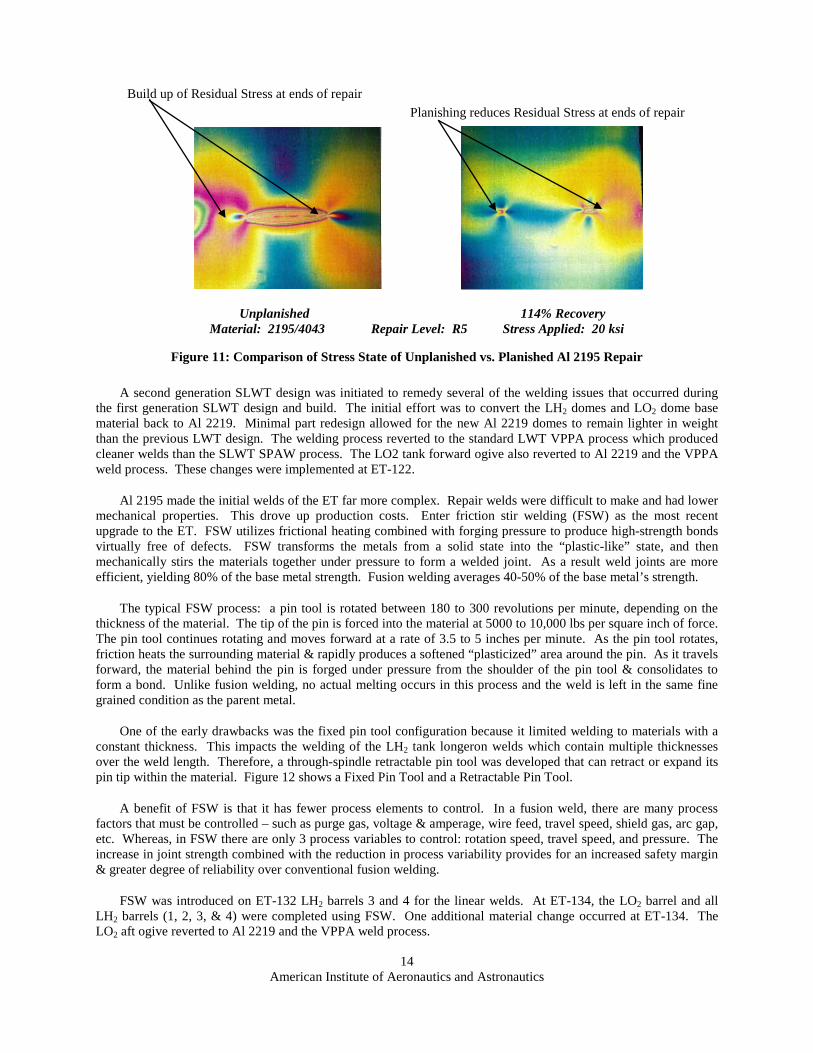
An approach was developed to mitigate the concentration of residual stress in Al 2195 weld repairs. A process was developed where the repair area bead and a portion of the adjacent original weld bead were planished (to toughen and smooth the surface of a metal by hammering or rolling it from both sides simultaneously), forcing the bead back into the joint. The joint spreads out, there by substantially reducing the recorded shrinkage and associated residual stress. Planishing activities, however, may form other cracks leading to additional weld repair/planish cycles prior to achieving an acceptable weld repair.
The welding team demonstrated that planishing weld repairs did indeed increase the weld repair properties and weld performance capabilities. The vehicle for the demonstration was an innovation for the SLWT program and it entailed the use of “wide panels”. Wide panel tensile specimens were configured to contain full size repairs with the restraint of surrounding non-repaired material to retain the residual stresses. The configuration allowed for load redistribution to be assessed during test. Nonplanished vs. planished samples were tested using photo stress material to show load redistribution. Figure 11 compares wide panel test articles with and without planishing. The typical wide panel configuration started with a 20 inch wide panel (weld length) and an overall length of 52 inches.
14 American Institute of Aeronautics and Astronautics
Unplanished 114% Recovery Material: 2195/4043 Repair Level: R5 Stress Applied: 20 ksi
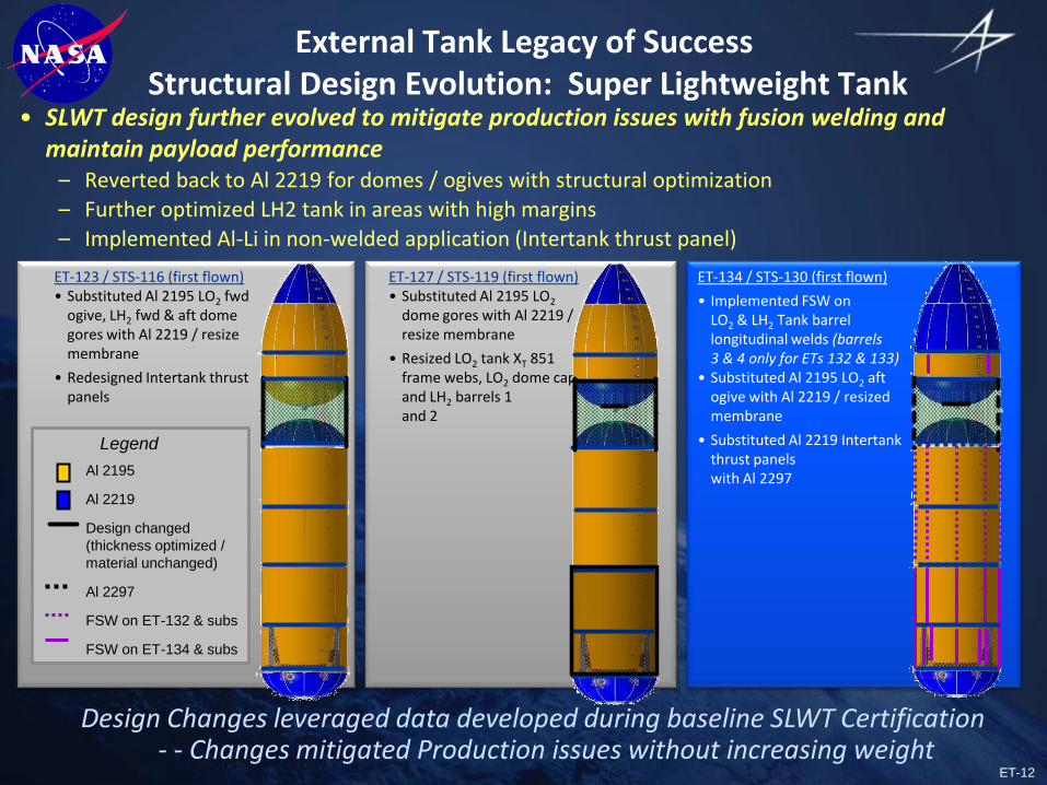
A second generation SLWT design was initiated to remedy several of the welding issues that occurred during the first generation SLWT design and build. The initial effort was to convert the LH2 domes and LO2 dome base material back to Al 2219. Minimal part redesign allowed for the new Al 2219 domes to remain lighter in weight than the previous LWT design. The welding process reverted to the standard LWT VPPA process which produced cleaner welds than the SLWT SPAW process. The LO2 tank forward ogive also reverted to Al 2219 and the VPPA weld process. These changes were implemented at ET-122.
Al 2195 made the initial welds of the ET far more complex. Repair welds were difficult to make and had lower mechanical properties. This drove up production costs. Enter friction stir welding (FSW) as the most recent upgrade to the ET. FSW utilizes frictional heating combined with forging pressure to produce high-strength bonds virtually free of defects. FSW transforms the metals from a solid state into the “plastic-like” state, and then mechanically stirs the materials together under pressure to form a welded joint. As a result weld joints are more efficient, yielding 80% of the base metal strength. Fusion welding averages 40-50% of the base metal’s strength.
The typical FSW process: a pin tool is rotated between 180 to 300 revolutions per minute, depending on the thickness of the material. The tip of the pin is forced into the material at 5000 to 10,000 lbs per square inch of force. The pin tool continues rotating and moves forward at a rate of 3.5 to 5 inches per minute. As the pin tool rotates, friction heats the surrounding material & rapidly produces a softened “plasticized” area around the pin. As it travels forward, the material behind the pin is forged under pressure from the shoulder of the pin tool & consolidates to form a bond. Unlike fusion welding, no actual melting occurs in this process and the weld is left in the same fine grained condition as the parent metal.
One of the early drawbacks was the fixed pin tool configuration because it limited welding to materials with a constant thickness. This impacts the welding of the LH2 tank longeron welds which contain multiple thicknesses over the weld length. Therefore, a through-spindle retractable pin tool was developed that can retract or expand its pin tip within the material. Figure 12 shows a Fixed Pin Tool and a Retractable Pin Tool.
A benefit of FSW is that it has fewer process elements to control. In a fusion weld, there are many process factors that must be controlled – such as purge gas, voltage & amperage, wire feed, travel speed, shield gas, arc gap, etc. Whereas, in FSW there are only 3 process variables to control: rotation speed, travel speed, and pressure. The increase in joint strength combined with the reduction in process variability provides for an increased safety margin & greater degree of reliability over conventional fusion welding.
FSW was introduced on ET-132 LH2 barrels 3 and 4 for the linear welds. At ET-134, the LO2 barrel and all LH2 barrels (1, 2, 3, & 4) were completed using FSW. One additional material change occurred at ET-134. The LO2 aft ogive reverted to Al 2219 and the VPPA weld process.
Figure 11: Comparison of Stress State of Unplanished vs. Planished Al 2195 Repair
Build up of Residual Stress at ends of repair Planishing reduces Residual Stress at ends of repair

15 American Institute of Aeronautics and Astronautics
The timeline for implementation of the various changes for the ET is shown in Table 2.
Month/Year Description of Activity
1/1972 President Nixon approves 3 element Space Shuttle
9/1973 NASA awards Martin Marietta Corporation design, development, & test of ET
5/1976 First ET test article (MPTA-098) assembled
7/1977 Fabrication begins on first Flight ET
9/1977 First ET test article (MPTA-098) delivered to NASA for test
12/1977 First ET tanking test conducted
6/1979 First ET delivered to NASA, STS-1 known as a Standard Weight Tank (SWT)
1/1980 NASA issues directive to lighten ET by at least 6,000 lbs
6/1980 Implementation of Light Weight (LWT) Design decreasing tank weight by 10,000 lbs
4/1981 First Space Shuttle flight (STS-1 @ 77,099 lbs empty)
Development of VPPA
11/1981 STS-2 Flight (SWT)
Development of VPPA
3/1982 First ET to fly without white paint on TPS (STS-3) weight savings 580 lbs
6/1982 First ET to fly without anti-geyser line (STS-4) weight savings 713 lbs
4/1983 First Light Weight flight, STS-6 (65,500 lbs empty) weight savings
1/1994 Implementation of VPPA
6/1983 STS-7 is last SWT flight (77,000 lbs empty)
8/1983 STS-8 Flight using first LWT configuration
1/1986 51L Challenger Accident
9/1988 Return to Flight with STS-26 LWT configuration
3/1993 Development of Al-Li by LM, Reynolds Metals, MSFC Huntsville
Figure 12: Friction Stir Weld Schematic and Macro Comparison
Fixed Pin Tool Retractable Pin Tool

16 American Institute of Aeronautics and Astronautics
Month/Year Description of Activity
2/1995 Initiate fabrication of ALTA (Aluminum Lithium Test Article)
6/1995 Initiate fabrication of ET-96/STS-91, first Super Light Weight Tank using Al-Li (SLWT)
5/1996 Implementation of SPAW
10/1997 First mating of major components using Al-Li alloy
1/1998 First SLWT tank, ET-96/STS-91 delivered to NASA
6/1998 First SLWT tank flight ET-96/STS-91 with Discovery (58,500 lbs empty)
6/2000 Implement change back to Al 2219 on LO2 & LH2 Domes, LO2 fwd ogive at ET122/STS-134
2000? Weld first FSW on LH2 barrel 3 & 4 (ET132/STS-128)
1/2003 Columbia breaks up on re-entry
7/2005 ET-121/STS-114 with Discovery marks the Return to Flight
8/2009 First flight using FSW barrels (ET-132/STS-128)
2/2010 ET-134/STS-130 flight with all FSW barrels (LH2 & LO2)
8/2011 Final Flight: ET-138/STS-135 with Atlantis
Table 2: ET Timeline: Welding Changes
The MAF production facility was divided into three distinct manufacturing areas called Weld Sub-Assembly (WSA) 1, 2, and 3. This allowed common manufacturing documentation for individual sub-assemblies required to complete either the LO2 or LH2 tank. WSA-1 provided the tooling to manufacture domes, a forward and aft for the LH2 Tank as well as a single dome for the LO2 tank; WSA-2 provided the tooling to complete Barrels, T-rings, and ogives; WSA-3 provided the tooling required to integrate the individual sub-assemblies into completed pressure vessels. Additional support hardware welding such as feedline and crossbeam welds were also a part of a WSA-2 remote area.
The LH2 and the LO2 tanks are shown in a flat profile in Figures 13 and 14. This allows a birds-eye view of the individual sections and welds required to complete each pressure vessel build.
Figure 13: LH2 Tank Weld Layout

17 American Institute of Aeronautics and Astronautics
Following completion of each sub-assembly, each weld was inspected for defects. In order to denote where a defect was found, the inside and outside surfaces of the tanks needed to be identified. The naming convention for the exterior surface was outer skin line while the interior surface was the inner skin line. Typical inspections included: 1) visual inspection to check for peaking and mismatch due to the weld as well as for non-conforming weld configurations; 2) radiography to check for defects internal to the weld; 3) liquid penetrant inspection to determine if any defects such as cracking or laps were open to the surface. When defects were found, repair practices such as sanding, grinding, and weld heat repairs were performed. Subsequent to any repair practice, the area worked was re-inspected to assure that the existing defect was removed and that no new defects were introduced.
V. Post Columbia ET Thermal Protection System Debris Minimization
Following the Columbia accident on February 1, 2003 the main focus for the ET Project was to minimize the debris produced by the ET during flight. The main forms of debris produced by the ET included ice and various forms of insulation. As such, the focus of design changes during the Return to Flight (RTF) activity was the minimization/elimination of areas that form ice and areas that lose insulation.
Ice formation was present in areas where insulation/heaters could not be applied adequately to eliminate exposed areas below freezing due to clearance requirements or other limitations. As active heating systems are complex and costly to maintain/operate, the goal for any post-Columbia design changes was to first look at passive systems/changes that could eliminate/reduce ice. This led to options that included changes in substrate material or configuration, addition of fairings or radiating fins, and/or use of different types of insulation. When passive changes did not provide enough reduction of ice in high risk areas, purges or heating systems were pursued.
The lightweight insulation used on the ET is sensitive to how it is applied and is not very damage tolerant. Therefore, post-Columbia work on the insulation targeted improved processes for applying the foam and increased efforts to protect the foam from damage. The improved processes for applying the foam mainly targeted the reduction of subsurface voids that could form in the foam as it was manually applied. A significant effort was put
Figure 14: LO2 Tank Weld Layout
Fwd Ogive
Aft Ogive
Barrel
Dome
Dome Cap

18 American Institute of Aeronautics and Astronautics
into spray technician training and recertification. High fidelity mockups were sprayed and dissected to quantify void formation. This process was repeated until acceptable results were obtained, and for critical applications high fidelity mockups were used as witness articles in conjunction with production sprays. The mockups would subsequently be tested and dissected and if unacceptable, the production spray would be removed and the process repeated. Additionally, nondestructive evaluation (NDE) techniques were developed and applied to critical debris locations on production tanks. Backscatter X-ray, terahertz imaging, and shearography were used to look for subsurface defects.
Areas that are subjected to cryopumping or cryoingestion accounted for the majority of the large foam losses from the ET, so design changes to mitigate foam loss were targeted heavily in areas where those conditions could exist. Cryopumping can exist when there is a “leak path” from the outside air to a subsurface void that is colder than the liquefaction temperature of air (approx -3190F). The air in the void will condense, creating a vacuum that will draw in more air that will continue to condense. This process will continue over many hours while the filled ET sits on the launch pad until either the void is filled or the leak path gets sealed (e.g. freezes). Upon warm-up, such as during flight, the air in the void will change back to gas but at a higher rate such that pressure builds up in the void causing the foam to fail and produce debris. Since liquid oxygen is at -2970F and liquid hydrogen is at -4230F, cryopumping can only occur in areas on or immediately adjacent to the hydrogen tank. Similarly, cryoingestion involves the same principles but is due to an internally fed void such as can exist near the Intertank to LH2 tank junction where gaseous nitrogen is used to purge the Intertank compartment. Design changes to reduce the potential for cryopumping and cryoingestion included reducing voids in both the foam and structure, filling of gaps, holes, and wiring bundles with filler material to eliminate leak paths, configuration changes to simplify foam application, and tool and scaffolding changes to enhance manual application of foam. Changes made to protect the insulation included new mats for working on or around the foam, new scaffolding to allow access to areas sensitive to foam damage, new guidelines for putting loads on the foam (i.e. weight limits), and new guidelines for accepting damage to foam.
Although the major RTF activity which targeted debris minimization including all of the following changes, only a few of these (shown in bold italics) will be discussed here in more detail:
1. Redesign of the bipod fitting and the elimination of the insulating ramp which contributed to the Columbia accident.
2. Redesign of the LO2 Feedline brackets to reduce ice and foam loss. 3. Redesign of the LO2 Feedline bellows to reduce ice. 4. Redesign of the LH2 to Intertank flange closeout configuration to reduce foam losses. 5. Redesign of the LH2 ice frost ramps to reduce foam losses. 6. Eliminate the LO2 and LH2 tank protuberance air load ramps to reduce foam loss. 7. Recertification of existing TPS foam on the tanks. 8. Addition of an in-flight video camera to help monitor debris performance.
1. Redesign of the Bipod Fitting and Elimination of the Insulating Ramp
The bipod configuration flown on the final Columbia mission (STS-107) is shown in Figure 15 and the Return to Flight configuration is shown in Figure 16. The original configuration had parts covered with a high density material called Super Light Ablator (SLA) which was there to protect the structure from ascent heating. A 150 watt calrod heater was used in the center of the spindle to keep the exposed end of the fitting which attached to the Orbiter strut from forming ice. This entire structure (fitting, heater, wiring, ablator, and miscellaneous hardware), minus the end of the fitting, was covered in a ramp of manually applied foam insulation to prevent/eliminate ice formation and provide protection from ascent heating. It was this foam ramp that came off and struck the Orbiter during the STS-107 Columbia mission. As a result, the main goal for the bipod redesign was to eliminate this large amount of foam as a potential debris source. Due to the direct sink to the LH2 tank and the necessity to have some parts bare it quickly became apparent that the new design would require a heater to minimize ice formation. See Figure 17 for an exploded view of the bipod hardware attached to the LH2 tank for the redesign. The final design made use of the original thermal isolator which was used between the LH2 tank wall and titanium fitting, the titanium fitting, and the internal Inconel spindle. Major new hardware components included four 300 Watt heaters,

19 American Institute of Aeronautics and Astronautics
a copper plate with 2 blocks to hold the heaters (2 each) placed between the fitting and isolator to spread the heat, and a new cover for the end of the fitting not attached to the strut.
Figure 17: Exploded View of RTF Bipod Fitting Redesign
Figure 16: RTF Bipod Configuration Figure 15: STS-107 Bipod Ramp

20 American Institute of Aeronautics and Astronautics
Figure 18 shows the fitting after installation but prior to the final foam closeout. It also shows the wires bonded as they exit the backside of the fitting and traverse over the Intertank to LH2 tank flange and enter the Intertank stringer on the forward side. Since the wires can be a reservoir for cryoingestion of N2 from the Intertank, the wires within 4 feet of the fitting were injected with a filler and bonded to the tank for the entire wire run on the LH2 tank side to try and prevent foam debris as a result of cryoingestion during loading and subsequent release of foam during drain of the LH2 tank in flight. In addition, the foam closeouts around the fitting were done in steps to eliminate/reduce voids in the foam and around the complex substructure. In some locations foam or paste was added to fill holes/gaps that could create reservoirs for cryopumping. The paste had an additional function of providing better contact between connecting structures allowing for more consistent performance of the heating system.
Due to the variations in contacts for this bipod structural stack-up and the range of weather conditions, the heaters were controlled based on feedback from two temperature sensors located on the backside of the fitting under the foam. The requirement for this complex control system was verified throughout the operation of this new design where no two fittings (+Y or –Y) required the exact same power settings from loading to loading and throughout the loading phases. One additional lesson learned with this control system was the requirement to offset the temperature readings. Due to the high conductivity of the wiring and the cold sink to which they were attached the temperature readings were not absolute and were dependent on the type of sensor and placement of the sensors in the final design.
Although foam losses still occurred occasionally in the region of the bipod fitting (and other locations on the hydrogen tank), post Columbia, the frequency and mass of foam loss was significantly reduced. It would be very difficult to completely eliminate this potential debris source without moving this attach structure to a location that is not susceptible to cryopumping/cryoingestion. However, with the increased in-flight video imagery post Columbia (namely the ET feedline camera), the time-of-release of the debris was often able to be verified and was found to agree with analytical predictions. Due to the physics governing the warmup of the hydrogen tank, such as the predictable nature of liquid depletion, the debris events due to this mechanism occurred relatively late in flight when there would be little aerodynamic drag decelerating the debris relative to the orbiter. Thus, the velocity of the debris impacts would be low and the risk of critical damage from these debris sources would likewise be acceptably low.
2. Redesign of the LO2 Feedline Brackets
During RTF II there was an initiative to reduce the debris coming from the LO2 Feedline brackets which included ice, foam, and possibly SLA. These brackets attach the LO2 feedline to the LH2 tank barrel at 5 locations and are designed to allow relative motion between the feedline and the LH2 tank during tanking/detanking cycles. Only the first four brackets, shown in Figure 19, which were identical and pose the highest risk to the Shuttle stack were redesigned. The brackets from ET-1 through ET-126 were made of aluminum and were covered with both SLA for heating and foam for ice protection. Due to the required motion of the brackets during loading/flight and clearance requirements, not enough foam could be installed to completely eliminate ice formation on these brackets. Figure 20 shows the critical icing areas which could form ice once the tank is loaded. Figure 21 shows typical ice formation as observed on the pad prior
to launch. During launch, these joints articulate which can crack both the ice and also TPS. Testing showed the majority of ice debris occurs early, just after liftoff, but the TPS debris can occur later in flight (near high dynamic pressure) and can pose a higher debris risk to the orbiter.
LH2 Tank
Intertank
Wire run
Figure 18: RTF Bipod Fitting Prior to Foam Closeout
Figure 19: LO2 Feedline Bracket Locations

21 American Institute of Aeronautics and Astronautics
Starting with ET-127 the aluminum brackets were replaced with redesigned titanium brackets which provided a totally passive ice mitigation solution. The redesigned bracket takes advantage of titanium’s high strength and low thermal conductivity (about 10 times lower than aluminum) which allows the bracket to fly with less TPS foam insulation and more exposed metal than the previous design. By decreasing the foam insulation, more surface area of the bracket is exposed and heat is transferred into the bracket through convection and radiation with the ambient environment. This results in a warmer overall bracket with a smaller “focused” area capable of producing ice during prelaunch. Also the high strength and high temperature capability allowed the titanium bracket to be thinner than
the aluminum configuration allowing more foam to be applied at the movable joints further reducing ice formation. Test results showed a minimum 70% reduction in ice mass with the redesigned bracket. Figure 22 shows the configuration before and after the redesign. The new design included a no gap “slip plane” between the outboard side of the feedline and the top part
of the bracket. This prevented ice formation in this articulating joint, eliminating foam cracking and subsequent foam loss from the bracket top in this location (which had been shown to be a high debris risk area).
Figure 22: LO2 Feedline Brackets Before and After Redesign
No gap/slip plane between bracket & F/L at outboard side of F/L
Figure 20: Critical Icing Areas Subject to Motion
Figure 21: LO2 Feedline Bracket Potential Debris Areas

22 American Institute of Aeronautics and Astronautics
3. Redesign of the LO2 Feedline Bellows to Minimize Ice Formation
The ET has 3 bellows on the LO2 feedline that runs along the LH2 tank at XT 1106, 1979, and 2026. Figure 23 shows the ice/frost formation that existed at the bellows opening for the LO2 feedline at XT 1106 prior to the redesign. Due to the location of the forward bellows relative to the Shuttle it was deemed the most critical location for debris liberation. As such, Kapton strip heaters were installed on the LO2 feedline bellows at XT 1106 to mitigate ice accumulation, starting with ET-121. The heater strips were adhesively bonded to the inner surface of the outer rain shield and the outer surface of the end convolute shield as shown in Figure 24. Each heater strip contained independent primary and secondary circuits for redundancy. Heater operation was controlled by monitoring circuit voltage and current, which eliminated the need for temperature sensors. The heater power to the rain shield and the convolute shield were approximately 30% and 70%, respectively, in order to maintain all requirements. These 2 surfaces needed to be warmed enough to prevent ice accumulation but not too much to affect the LO2 propellant running through the line or to violate the bond line temperature limit of the foam adhered to the outside of the two shields. Placement of the heater on the two shields was also critical to the success of this redesign and as such the installation requirements were stringent.
Original concepts to eliminate this ice included purges, an Atlas type boot, heaters, filling the cavity with some
type of insulation, or targeted heating but all of these concepts had issues. Heaters were not pursued heavily in the beginning due to the active heating system required and initial placement of the heaters on the metal in locations that indicated the heater power was excessive and propellant quality would be negatively impacted. Due to the small gap between the bellows shield and the convolute shield, installation of the heater was also a challenge to implementing a design with a heater.
Figure 26: RTF Bellows OML with Drip Lip Figure 25: Pre RTF LO2 Feedline Bellows OML
Figure 24: RTF LO2 Feedline Bellows with Heater
Figure 23: Pre RTF LO2 Feedline Bellows at XT 1106
Bellows
Drip Lip

23 American Institute of Aeronautics and Astronautics
While no heaters were used at XT 1979 and XT 2026 due to reduced risk of critical damage to the Orbiter from ice debris, the outer mold line (OML) of the foam on the bellows shield was redesigned to reduce the amount of ice/frost that formed at the opening by a minimum of 40%. Condensate run-off and the configuration of the foam on the rain shield were found to be major contributors to ice build-up. The pre-RTF LO2 feedline bellows configuration of the foam is shown in Figure 25. Figure 26 shows the new OML that was implemented during RTF at the 3 bellows locations which resulted from the addition of the foam labeled ‘drip lip’.
VI. Key Technical Issues and Resulting Lessons Learned
Following the Shuttle’s Return to Flight in 2006, the ET Project faced several technical challenges that put the entire Program at risk. The key issues, which involved each of the primary systems on the ET, are listed below. The items high-lighted by bolded italics will be discussed in further detail.
• Space Shuttle Main Engine (SSME) Cut Off Sensor Circuit Intermittent Failures (Electrical System)
• Ground Umbilical Carrier Plate (GUCP) GH2 Leakage (Propulsion System)
• Intertank Stringer Cracking (Structural System)
• ET-124 Hail Damage Recovery (Thermal Protection System)
• Restoration of ET-122 following damage from Hurricane Katrina (All Systems)
Each issue required an extensive investigation to identify the proximate root cause, establishing the necessary corrective action, and defining / executing the implementation plans in a way such that the impacts to the overall program milestones were minimized. The following section will briefly describe each issue, the resulting corrective action, and key lessons learned.
Space Shuttle Main Engine Cut Off Sensor Circuit Intermittent Failures
Four sensors (Figure 27) are located at the bottom of the LH2 tank and serve as a back-up system to ensure that the SSMEs never run LO2 rich due to either a leak in the LH2 tank or issues within the SSMEs. Premature depletion of LH2 would result in catastrophic explosion of the SSME. Small platinum filaments are housed within each sensor (Figure 28) and are used to detect changes in resistance as a function of temperature. Changes in resistance are converted to voltage signals which are then used by the Orbiter’s on-board computers to determine the liquid level within the LH2 tank.
Depletion Sensors Installed on Shock Mount
Depletion Sensors Installed on Shock Mount
Figure 27: Depletion Sensor Location

24 American Institute of Aeronautics and Astronautics
Prior to STS-129, sensor circuit anomalies (open circuit) would randomly occur during the filling of the LH2 tank at cryogenic temperature and subsequently regain functionality following tank drain at ambient conditions. Previous investigations were unable to conclusively identify the root cause, but the decision was made to implement process improvements to the sensor manufacturing process as the sensors were deemed to be the most likely cause. Several flights occurred with no issues observed; but during cryogenic loading for the STS-129 mission, multiple sensor circuits failed simultaneously. A subsequent instrumented tanking test was performed and isolated the fault to the feed thru connector (Figure 29). The specific root cause was determined to be the result of liquid air / condensation that would form on the pin / socket parts on the external side of the feed thru connector at cryogenic conditions (Figure 30). With the material formed on the mating surfaces, any relative motion between the two surfaces would result in an open circuit to occur at cryogenic temperatures
which would then resume functionality once the material had melted (i.e. post drain ambient conditions). Once the issue was isolated to the external mating connectors at the feed thru connector, the necessary corrective action was quickly
identified and certified for flight. The corrective action
required the implementation of soldered connection between the pin and sockets to eliminate the necessary contributors to the fault (i.e. sliding components and contamination). The system has worked flawlessly since the implementation of the corrective action.
Key lessons learned included:
1. Requires a physics-based under-standing or scenario to lead the investigation and corrective action plans.
2. Group think and outside influence can confound the situation.
ET-124 Hail Damage Restoration
ET-124 suffered significant impact damage due to a freak hail storm while the Shuttle s tack was on the launch pad prior to the STS-128 mission. Over 5,000 individual impacts were incurred on the TPS system. The damage required that the stack be rolled back to the Vertical Assembly Building for detailed assessment and repairs. A majority of the more significant impact were located on the debris critical zone section of the forward LO2 tank. Following a detailed assessment of each damage location via tactile inspection, the damage sites were grouped by severity and location. Next, unique engineering requirements were developed based on the as-built configuration (i.e. TPS thickness) and weather conditions. This was critical to the overall effort as the intent was to remove as little of the original TPS as possible while ensuring that the potential for ice formation and/or TPS liberation is minimized. The
Figure 28: Depletion Sensor
Figure 29: Feed Through Connector
Figure 30: Pin Contamination
Figure 31: ET-124 Hail Damage Repairs

25 American Institute of Aeronautics and Astronautics
repairs (Figure 31) consisted of sand/blends for minor damage sites, local filling of more significant damage sites, and finally large manual sprays where the damage density was too great to address individually. Each repair method was verified by first validating the process, and, then performing tests to the critical aero-thermal ascent environments.
The restoration of ET-124 preserved a valuable flight asset and minimized what could’ve been a major impact to the Shuttle program manifest. Post flight evaluation (Figure 32) showed that all of the hail damage repairs performed flawlessly with no debris events observed.
Key lessons learned included:
1. Think ‘outside the box’ to develop unique requirements and processes for unique circumstances.
2. Rely on efficient and conservative testing to bound performance and minimize risk exposure.
ET-137 Intertank Stringer Cracks
Following the scrub of STS-133 launch attempt due to launch commit criteria limit violation for GH2 leakage at the ground umbilical disconnect, a large TPS crack was observed adjacent to the LO2 / Intertank flange region (Figure 33). Subsequent TPS removal revealed that the TPS crack (Figure 34) was the result of cracks in the base of the Al-Li 2090 Intertank stringers where the stringers are mechanically attached to the Intertank skin panel. Five stringers were observed to exhibit similar cracks. An extensive investigation ensued to identify the root cause and assess / implement corrective actions. The cause of the cracks was isolated to material lots that were shown to have reduced fracture toughness and uncharacteristic crack growth behavior. Those factors combined with higher assembly stresses on the LO2 tank end of the stringers contributed to the observed cracks. Nondestructive evaluation of the LH2 / Intertank flange confirmed crack-free conditions. The corrective action required a design change to the LO2 tank side stringer ends to incorporate reinforcements on the stringer feet called radius blocks. The effectiveness of the radius block change was demonstrated by numerous component level tests and structural analyses. Radius blocks were implemented on the remainder of the ET fleet and successfully flown with no issues.
Figure 34: STS-133 Intertank Stringer Radius Block Repair
Figure 33: STS-133 TPS Crack as Seen On Pad
Figure 32: Hail Damage Repair Flight Performance

26 American Institute of Aeronautics and Astronautics
Key lessons learned include:
1. Ensure proper requirements and trending data are implemented for Al-Li materials used in a cryogenic environment
2. Limit or avoid using Al-Li 2090 in a cryogenic environment.
3. Use simple tests to fullest extent possible to rapidly develop engineering data to help guide the failure investigation and corrective actions.
VII. Summary
Over the past 30+ years, the Space Shuttle’s External Tank has changed very little in its outward appearance, but inwardly has been a program of continuous evolution. Numerous challenges were presented to and met by the ET contractor and NASA team. These challenges included achieving significant weight reductions (from 76,000 lbs to 58,500 lbs- nearly 25%) that enabled construction of the International Space Station in a Russian-accessible orbit. Weight savings were made possible by efficient structural design firmly anchored in testing and through use of new lightweight aluminum-lithium alloys. Numerous welding advancements were made throughout the program, culminating in the first use of friction stir welding on a human-rated launch vehicle. While ice and foam debris had always been a concern, following the Columbia accident significant debris reduction efforts were successful in reducing debris risks which culminated in the safe completion of the Shuttle Program.

ET-1
External Tank ProgramLegacy of Success
Ken Welzyn – NASA MSFCJeff Pilet – Lockheed Martin
AIAA ConferenceLong Beach CA 9/27-28/2011
ET-138 Rollout 7/8/10

ET-2
External Tank Legacy of Success
• Agenda
– External Tank Overview
– Design Evolution
• Super Lightweight Tank
– Return to Flight DebrisMinimization
– Technical IssueResolution
– Summary
Final MissionSTS-135/ ET-138
07/08/11(11:29 a.m. EDT )
STS-135/ ET-138Successful Landing 07/21/11 (5:57 a.m. EDT)
ET-138
Clean Tank
ET-3
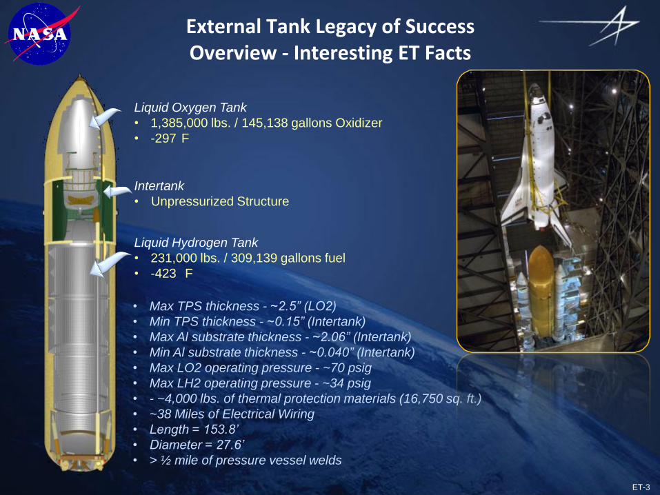
External Tank Legacy of SuccessOverview - Interesting ET Facts
Intertank
• Unpressurized Structure
Liquid Oxygen Tank
• 1,385,000 lbs. / 145,138 gallons Oxidizer
• -297 F
Liquid Hydrogen Tank
• 231,000 lbs. / 309,139 gallons fuel
• -423 F
• Max TPS thickness - ~2.5” (LO2)
• Min TPS thickness - ~0.15” (Intertank)
• Max Al substrate thickness - ~2.06” (Intertank)
• Min Al substrate thickness - ~0.040” (Intertank)
• Max LO2 operating pressure - ~70 psig
• Max LH2 operating pressure - ~34 psig
• - ~4,000 lbs. of thermal protection materials (16,750 sq. ft.)
• ~38 Miles of Electrical Wiring
• Length = 153.8’
• Diameter = 27.6’
• > ½ mile of pressure vessel welds

ET-4
Changes Implemented to Reduce Debris
• Notable Events
• ATP – 1973
• 1st Production Article – 1977
• 1st Flight Article Complete – 1979
• 1st SLWT Complete – 1998
• TPS design changes implemented post-Columbia (RTF) to reduce debris - 2003
• All manifested tanks completed and delivered to KSC – 2010
• 139 tanks manufactured in total
External Tank Legacy of SuccessOverview
1981 - 1983
S 1981 - 1998
1998 - 2011
External Tank Evolution / Weight
• HWT (1981 – 1983): 76,000 lb. (6 flown)
• LWT (1981 – 1998): 66,000 lb. (86 flown)
• SLWT (1998 – 2011: 58,500 lb. (43 flown)
6 flown
86 flown
21 flown
Tank structure ‘evolved’ to improve payload performance and producibility
22 flown

ET-5
Thrust Struts
(1 each side)
Bipod
Attachment LO2 Feedline and
Fairing
Intertank
Nose Cone
LO2 Fwd Ogive
LO2 Aft Ogive
LO2 Barrel
Slosh Baffle Assy
Aft Dome and
Vortex Assy
Ring Frames (2)
LO2 Aft Ogive
GO2 Pressline and
Electrical Cable Tray
Structural
Crossbeam
Intertank Stringer
Panels (6)
Intertank Thrust
Panels (2)
Fwd ET/SRB
Attachments (2)
GH2 Pressline
and Fairing
GH2 Pressline and
Electrical Cable Tray
LO2 TankLH2 Tank
LH2 Aft dome
and Vortex Assy
Orthogrid Barrel
Panels (32)
LO2 and LH2
Umbilicals
Aft ET/Orb
Attachments (2)
Aft ET/SRB
Attachments (Upper
and Lower each side)
Vertical Struts
(1 each side)
Ring
Frames
(5)
LH2 Fwd Dome
System Structure Propulsion Electrical Thermal Protection Interface Hardware
• LO2 Tank
• Intertank
• LH2 Tank
• Propellant Feed
• Pressurization
• Vent/Relief
• Environmental Conditioning
• Instrumentation (sensors, heaters, and associated cabling)
• Lightning Protection
• ET Camera
• Foam (Spray and Pour)
• Ablators (Spray and Molded)
• Composites
• ET/SRB
• ET/Orbiter
• ET/Ground
External Tank Legacy of SuccessOverview

ET-6
External Tank Legacy of SuccessStructural Design Evolution: Super Lightweight Tank
• Goal
– Optimize External Tank structural mass to support ISS construction
• ~7500 lbm reduction required to achieve 51.6° orbital inclination with ISS payload
• Super Lightweight Tank (SLWT) program initiated to provide performance
• Challenges
– Required parallel development of lightweight aluminum-lithium material, and associated manufacturing processes, and design
– Aggressive schedule to support ISS program
– Structural verification program constrained by funding and schedule
• Dedicated full-scale, cryogenic STAs not planned
– Significant production impacts caused by Al-Li alloy weld-related rework
• How’d We Do It?
– Leveraged government and corporate research with Al-Li alloys
– Used new orthogrid design for LH2 tank barrels to optimize performance
– Developed innovative design / material verification and acceptance test program
– Fully engaged industry experts and technical community early in design verification
– Evolved design to mitigate production issues

ET-7
LH2slwt.pct
External Tank Legacy of SuccessStructural Design Evolution: Super Lightweight Tank
• Super Lightweight Tank (SLWT) Change from Lightweight (LWT)
• Substitute Al 2195 for Al 2219• Redesign to Orthogrid Waffle• Optimize TPS Application
• Substitute Al 2090 for Al 2024 and Al 7075
Intertank
= Al Li 2090, 2195
= Other Redesigned Parts
hibbard_LO2tank.pct
hibbard SLWT_I/T.pct
LH2 Tank
• Substitute Al 2195 for Al 2219• Resize
LO2 Tank>4000 lbs wt savings
>1500 lbs wt savings
>600 lbs wt savings

ET-8
External Tank Legacy of SuccessStructural Design Evolution: Super Lightweight Tank
• Major configuration change implemented on SLWT LH2 Tank barrels
– Was: Al 2219 T-stiffened panels (SWT and LWT designs)
– Now: Al 2195 Orthogrid panels (SLWT)
– Required development of new manufacturing process for machining, forming, and welding of barrel assemblies
Standard Weight (SWT) and Lightweight (LWT) – Al 2219 alloy
Super Lightweight (SLWT) – Al 2195 alloy

ET-9
External Tank Legacy of SuccessStructural Design Evolution: Super Lightweight Tank
Existing Data Base
Component Tests(strength &
stability)
Independent Analysis (stability)
Proof Tests (strength, fracture)
Protoflight Tests(stability)
Material Acceptance
Proof Tests
Protoflight Tests
Nondestructive Evaluations
Design Verification
Acceptance Verification
• Innovative structural verification plan established for SLWT
– An independent Verification Team was formed early with industry experts
– Verification Team established plan that verified each failure mode by either test, flight history, or independent analyses
– Team utilized wealth of data from SWT and LWT heritage
– STA, GVTA, MPTA, DDT&E and 90 flights
Aluminum Lithium Test Article (ALTA)
Analysis
Partial / Complimentary
Total Tank

ET-10
External Tank Legacy of SuccessStructural Design Evolution: Super Lightweight Tank
• SLWT Verification Process
Test-based Verification performed for all Hardware and Failure Modes- - Program Mitigated Requirement for Full-scale Cryogenic Test
ALTA at MSFC
LO2 Tank Independent Stability Analysis (LaRC)
ALTA used to verify multiple hardware elements and failure modes
- - LH2 Barrel Panels, LO2 Dome, Fusion Welding

ET-11
External Tank Legacy of SuccessStructural Design Evolution: Super Lightweight Tank
• ALTA Capability Test
– Structure test demonstrated > ultimate load
ET-12
External Tank Legacy of SuccessStructural Design Evolution: Super Lightweight Tank
• SLWT design further evolved to mitigate production issues with fusion welding and maintain payload performance
– Reverted back to Al 2219 for domes / ogives with structural optimization
– Further optimized LH2 tank in areas with high margins
– Implemented Al-Li in non-welded application (Intertank thrust panel)
ET-123 / STS-116 (first flown)• Substituted Al 2195 LO2 fwd
ogive, LH2 fwd & aft dome gores with Al 2219 / resize membrane
• Redesigned Intertank thrust panels
ET-134 / STS-130 (first flown)
• Implemented FSW on LO2 & LH2 Tank barrel longitudinal welds (barrels3 & 4 only for ETs 132 & 133)
• Substituted Al 2195 LO2 aft ogive with Al 2219 / resized membrane
• Substituted Al 2219 Intertank thrust panelswith Al 2297
ET-127 / STS-119 (first flown)• Substituted Al 2195 LO2
dome gores with Al 2219 / resize membrane
• Resized LO2 tank XT 851 frame webs, LO2 dome cap and LH2 barrels 1 and 2
Legend
Al 2195
Al 2219
Design changed
(thickness optimized /
material unchanged)
Al 2297
FSW on ET-132 & subs
FSW on ET-134 & subs
Design Changes leveraged data developed during baseline SLWT Certification- - Changes mitigated Production issues without increasing weight

ET-13
Typical FSW Tool
Weld Direction
FSWTool
AdvancingSide
RetreatingSide
FSWTool
Direction of Tool
Rotation
Weld Direction
Steel Anvil
Base Metal
External Tank Legacy of SuccessStructural Design Evolution: Super Lightweight Tank
• State-of-the-Art FSW Process Improves Robustness, Producibility, and Allows for Design Optimization
FSW Fusion Welding
Pin
Shoulder
Shank

ET-14
External Tank Legacy of SuccessStructural Design Evolution: Super Lightweight Tank
• Results
– 1st SLWT tank delivered in 44 months
– SLWT tanks delivered to support program requirements andhave performed flawlessly
– SLWT tank enabled ISS construction by improving Shuttle payload capability
– ISS construction required international collaboration International Teamwork made possible by SLWT
STS-91 / ET-96 International Space Station photographed by STS-132 crew

ET-15
• Engage industry experts early in design verification cycle
• Verification program should be test-based and failure mode specific
• Tests to design capability are critical to understand margins
• Tests should be performed incrementally to reduce program risk
• Component – Large scale – Acceptance
• Protoflight tests can be used when ultimate load tests not practical
• Independent analyses can be used to extend test-based data for similarity verification
• Leverage ALL previous test, analysis, and engineering experience data to the fullest extent to minimize risk
• Designs should ‘evolve’ to more exotic material and manufacturing
External Tank Legacy of SuccessStructural Design Evolution: Super Lightweight Tank
Key Lessons Learned

ET-16
External Tank Legacy of SuccessReturn to Flight Debris Minimization
• Goal– Post-Columbia ET Project directed to eliminate
critical debris sources by redesign or provideflight rationale
• Challenges– Limited understanding of TPS material, failure
modes, and analysis methods• TPS debris never considered a ‘safety of
flight concern’ before STS-107
– Extreme amount of distrust / anxiety within technical and programmatic communities
– Schedule pressure to Return to Flight – 6 month target for RTF initially established…
– Debris expectations not effectively communicated or understood coupled with unexpected foam loss on RTF I
– Limited ability to effectively communicate integrated debris risk
– TPS performance after RTF I resulted in stand-down to perform additional debris mitigations
– Hurricane Katrina devastated south Louisiana following RTF I
– TPS scope increase from RTF I and RTF II jeopardized ET’s ability to ‘Meet the Manifest’

ET-17
External Tank Legacy of SuccessReturn to Flight Debris Minimization
Performed extensive test program to document and characterize TPS application process performance
Performed failure mode tests to relate process data to debris expectations
Enhanced flight imagery assets and post flight assessment process to further correlate understanding of failure modes
Major Tests, Analysis, and In-Flight Imagery Data Led to Improved Understanding of Failure Modes
Implemented significant design changes leveraging test and flight data

ET-18
Critical Debris Threats Eliminated Through Innovative Design Changes
External Tank Legacy of SuccessReturn to Flight Debris Minimization
LO2 Feedline Bellows TPS Drip Lip(3 Stations) & Heater @ XT 1106
Redesigned Bipod Fitting & TPS Closeout (+Y and –Y)
LO2 Feedline Bracket Ice Formation and TPS Cracking
Risk Reduced (4 Stations)- No TPS Loss Observed
Before
After
After
Before
Before
After

ET-19
• Post RTF TPS Performance Dramatically Better than Previous Designs
STS-4/ET-406/27/82
20” L x 8” W
15” L x 8” W15” L x 8” W
• LH2 tank PAL ramp loss
• Intertank foam loss (two tone acreage foam) 18 divots, 3” to 30” diameter
STS-126 / ET-12911/14/08
STS-26/ET-1907/29/85
External Tank Legacy of SuccessReturn to Flight Debris Minimization

ET-20
0.000
0.100
0.200
0.300
0.400
0.500
0.600
0.700
0.800
0.900
1.000
1.100
1.200
1.300
1.400
1.500
1.600
1.700
Redesigns Significantly Reduced Debris Risk and Orbiter Tile Damage
Large Ramp Debris
Eliminated – LH2 Tank
Flange Closeout
Redesigned
Debris Potential Further Reduced
- - LH2 Ice Frost Ramp and
LO2 Feedline Bracket Yoke
Redesigned
TPS
Loss
/ E
T (l
bm
)
Mission
Debris Potential for
Pre-Redesigned
External Tank TPS
Hardware
STS-132 Orbiter Lower Surface Damage
Total = 95 4 > 1”
Lowest in History
Total Elliptical Volume of
Orbiter Tile Damage for
Recent Mission
Significantly Reduced
External Tank Legacy of SuccessReturn to Flight Debris Minimization

ET-21
Outstanding External Tank Performance for STS-135 / ET-138- - Last Tank was the Best Tank!!
External Tank Legacy of SuccessReturn to Flight Debris Minimization
• Separation imagery confirms TPS performance improvements

ET-22
• Ensure early and clear understanding of requirements
• Acknowledge verification limitations and effectively communicate risk to program management
• Ensure a strong physics-based understanding of failure modes with test-demonstration
• Be cautious of implementing excessive process controls without having a good understanding of failure modes
• Critical to communicate and educate all stakeholders early and often
• Can be difficult but the payoff is HUGE!!
Key Lessons Learned
External Tank Legacy of SuccessReturn to Flight Debris Minimization

ET-23
External Tank Legacy of SuccessTechnical Issue Resolution
• ET Team Confronted with Numerous Complex Issues during RTF Era
S7-2 CracksS6-2 Crack
ET-137 Intertank Stringer Cracks Observed during
Loading of STS-133
ET-122 Damaged by Hurricane Katrina at MAF
ET-124 Damaged by Hail Storm on Pad

ET-24
• Let physics not emotion drive the solution set
• Maximum use of test data to demonstrate critical failure modes
• Rapid, simplistic tests often provide the greatest insight
• Critical to communicate and educate all stakeholders early and often
• Can be difficult but the payoff is HUGE!!
Key Lessons Learned
External Tank Legacy of SuccessTechnical Issue Resolution

ET-25
External Tank Legacy of SuccessSummary
• ET Design Continuously Evolved to Optimize Performance
• Structural weight reduced ~25% since beginning of program
• Debris performance optimized to fullest extent possible
• Significant technology demonstrations achieved on ET Program
• Developed and implemented design and manufacturing processes with Aluminum-Lithium
• First use of Friction Stir Welding in human rated launch vehicle
• Dedicated, cohesive team of engineers and technicians from NASA and LM resolved numerous complex issues to meet program milestones
• Hail damaged TPS, ECO sensors, and Intertank stringer cracks etc.
• External Tank Team delivered on it’s commitment to the Shuttle Program and the Astronauts
• Focused Dedication to Continuous Learning and Improvement
• Last Tank was the Best Tank – Finished Strong!!