extraction and scrubber neutralization of acid fumes and reaction gases
DESCRIPTION
Scrubber Extraction and neutralization of acid fumes and reaction gasesTRANSCRIPT

B-414ScrubberOperation Manual
96701 en


Table of contents
3 B-414 Operation Manual, Version D
Table of contents
1 About this manual . . . . . . . . . . . . . . . . . . . . . . . . . . . . . . . . . . . . . . . 51.1 Reference documents . . . . . . . . . . . . . . . . . . . . . . . . . . . . . . . . . . 51.2 Abbreviations . . . . . . . . . . . . . . . . . . . . . . . . . . . . . . . . . . . . . . 5
2 Safety. . . . . . . . . . . . . . . . . . . . . . . . . . . . . . . . . . . . . . . . . . . . . . 62.1 User qualifi cation . . . . . . . . . . . . . . . . . . . . . . . . . . . . . . . . . . . . 62.2 Proper use . . . . . . . . . . . . . . . . . . . . . . . . . . . . . . . . . . . . . . . 62.3 Improper use . . . . . . . . . . . . . . . . . . . . . . . . . . . . . . . . . . . . . . 62.4 Warning notices used in this manual . . . . . . . . . . . . . . . . . . . . . . . . . . 72.5 Product safety. . . . . . . . . . . . . . . . . . . . . . . . . . . . . . . . . . . . . . 72.5.1 Instrument-related hazards . . . . . . . . . . . . . . . . . . . . . . . . . . . . . . . 72.5.2 Other hazards . . . . . . . . . . . . . . . . . . . . . . . . . . . . . . . . . . . . . . 82.5.3 Safety measures . . . . . . . . . . . . . . . . . . . . . . . . . . . . . . . . . . . . 82.5.4 Safety elements . . . . . . . . . . . . . . . . . . . . . . . . . . . . . . . . . . . . . 82.6 General safety rules . . . . . . . . . . . . . . . . . . . . . . . . . . . . . . . . . . . 9
3 Technical data . . . . . . . . . . . . . . . . . . . . . . . . . . . . . . . . . . . . . . . . 103.1 Scope of delivery . . . . . . . . . . . . . . . . . . . . . . . . . . . . . . . . . . . 103.1.1 Standard instrument. . . . . . . . . . . . . . . . . . . . . . . . . . . . . . . . . . 103.1.2 Scrubber with condenser . . . . . . . . . . . . . . . . . . . . . . . . . . . . . . . 103.1.3 Scrubber with cold trap . . . . . . . . . . . . . . . . . . . . . . . . . . . . . . . . 113.1.4 Scrubber complete with condenser and reaction stage . . . . . . . . . . . . . . . . 113.1.5 Standard accessories . . . . . . . . . . . . . . . . . . . . . . . . . . . . . . . . . 123.1.6 Optional accessories . . . . . . . . . . . . . . . . . . . . . . . . . . . . . . . . . 123.1.7 Upgrade. . . . . . . . . . . . . . . . . . . . . . . . . . . . . . . . . . . . . . . . 133.2 Technical data overview . . . . . . . . . . . . . . . . . . . . . . . . . . . . . . . . 133.3 Materials used. . . . . . . . . . . . . . . . . . . . . . . . . . . . . . . . . . . . . 133.4 Recommended consumables . . . . . . . . . . . . . . . . . . . . . . . . . . . . . 14
4 Description of function . . . . . . . . . . . . . . . . . . . . . . . . . . . . . . . . . . . 154.1 Functional principle of the Scrubber . . . . . . . . . . . . . . . . . . . . . . . . . . 154.2 Scrubber capacity. . . . . . . . . . . . . . . . . . . . . . . . . . . . . . . . . . . 164.3 Condenser . . . . . . . . . . . . . . . . . . . . . . . . . . . . . . . . . . . . . . 174.4 Cold trap . . . . . . . . . . . . . . . . . . . . . . . . . . . . . . . . . . . . . . . 174.5 External receiving vessel (option) . . . . . . . . . . . . . . . . . . . . . . . . . . . 18
Read this manual carefully before installing and running your system and note the safety precautions in chapter 2 in particular. Store the manual in the immediate vicinity of the instrument, so that it can be consulted at any time.No technical modifi cations may be made to the instrument without the prior written agreement of Buchi. Unauthorized modifi cations may affect the system safety or result in accidents. This manual is copyright. Information from it may not be reproduced, distributed, or used for competi-tive purposes, nor made available to third parties. The manufacture of any component with the aid of this manual without prior written agreement is also prohibited.If you need another language version of this manual, you can download it at www.buchi.com.

Table of contents
4 B-414 Operation Manual, Version D
5 Putting into operation . . . . . . . . . . . . . . . . . . . . . . . . . . . . . . . . . . . . 195.1 Installation site. . . . . . . . . . . . . . . . . . . . . . . . . . . . . . . . . . . . . 195.2 General commissioning procedure for all Scrubber models . . . . . . . . . . . . . . 195.3 Commissioning the Scrubber with condenser / cold trap and reaction vessel . . . . . 205.4 External receiving vessel (optional). . . . . . . . . . . . . . . . . . . . . . . . . . . 215.5 Hose connections . . . . . . . . . . . . . . . . . . . . . . . . . . . . . . . . . . . 215.5.1 Hose connections of the basic model . . . . . . . . . . . . . . . . . . . . . . . . . 215.5.2 Hose connections for Scrubber with condenser / cold trap . . . . . . . . . . . . . . 235.5.3 Hose connections for Scrubber with condenser / cold trap and reaction vessel . . . . 245.6 Electrical connections . . . . . . . . . . . . . . . . . . . . . . . . . . . . . . . . . 255.7 Preparing washing solutions. . . . . . . . . . . . . . . . . . . . . . . . . . . . . . 255.7.1 Washing solutions for acidic vapors and gases . . . . . . . . . . . . . . . . . . . . 255.7.2 Washing solutions for alkaline vapors and gases . . . . . . . . . . . . . . . . . . . 255.7.3 Color indicator. . . . . . . . . . . . . . . . . . . . . . . . . . . . . . . . . . . . . 255.8 Filling up the prepared washing solution . . . . . . . . . . . . . . . . . . . . . . . . 26
6 Operation . . . . . . . . . . . . . . . . . . . . . . . . . . . . . . . . . . . . . . . . . . 276.1 Typical applications . . . . . . . . . . . . . . . . . . . . . . . . . . . . . . . . . . 276.2 Operation . . . . . . . . . . . . . . . . . . . . . . . . . . . . . . . . . . . . . . . 28
7 Maintenance . . . . . . . . . . . . . . . . . . . . . . . . . . . . . . . . . . . . . . . . . 297.1 Housing . . . . . . . . . . . . . . . . . . . . . . . . . . . . . . . . . . . . . . . . 297.2 Glass parts . . . . . . . . . . . . . . . . . . . . . . . . . . . . . . . . . . . . . . 297.3 Tubes / tube connectors . . . . . . . . . . . . . . . . . . . . . . . . . . . . . . . 297.4 Sealing system . . . . . . . . . . . . . . . . . . . . . . . . . . . . . . . . . . . . 297.4.1 Cleaning the seals . . . . . . . . . . . . . . . . . . . . . . . . . . . . . . . . . . . 307.4.2 Replacing the seals . . . . . . . . . . . . . . . . . . . . . . . . . . . . . . . . . . 307.5 Washing insert . . . . . . . . . . . . . . . . . . . . . . . . . . . . . . . . . . . . 307.6 Washing solution . . . . . . . . . . . . . . . . . . . . . . . . . . . . . . . . . . . 317.7 Pump . . . . . . . . . . . . . . . . . . . . . . . . . . . . . . . . . . . . . . . . . 317.8 Power supply fuses . . . . . . . . . . . . . . . . . . . . . . . . . . . . . . . . . . 327.9 Silencer . . . . . . . . . . . . . . . . . . . . . . . . . . . . . . . . . . . . . . . . 327.10 Functional test. . . . . . . . . . . . . . . . . . . . . . . . . . . . . . . . . . . . . 327.11 Customer service . . . . . . . . . . . . . . . . . . . . . . . . . . . . . . . . . . . 32
8 Troubleshooting . . . . . . . . . . . . . . . . . . . . . . . . . . . . . . . . . . . . . . . 338.1 Malfunctions and their remedy . . . . . . . . . . . . . . . . . . . . . . . . . . . . 33
9 Shutdown, storage, transport and disposal . . . . . . . . . . . . . . . . . . . . . . . . 349.1 Storage and transport . . . . . . . . . . . . . . . . . . . . . . . . . . . . . . . . . 349.2 Disposal . . . . . . . . . . . . . . . . . . . . . . . . . . . . . . . . . . . . . . . . 34
10 Spare parts . . . . . . . . . . . . . . . . . . . . . . . . . . . . . . . . . . . . . . . . . 3510.1 Spare parts on the exploded instrument view . . . . . . . . . . . . . . . . . . . . . 3510.2 Miscellaneous . . . . . . . . . . . . . . . . . . . . . . . . . . . . . . . . . . . . . 36
11 Declarations and requirements. . . . . . . . . . . . . . . . . . . . . . . . . . . . . . . 3711.1 FCC requirements (for USA and Canada) . . . . . . . . . . . . . . . . . . . . . . . 3711.2 Declaration of conformity . . . . . . . . . . . . . . . . . . . . . . . . . . . . . . . 38

1 About this manual
5 B-414 Operation Manual, Version D
1 About this manual
This manual describes the Scrubber and provides all information required for its safe operation and to maintain it in good working order.It is adressed to laboratory personnel in particular.
NOTEThe symbols pertaining to safety (WARNINGS and ATTENTIONS) are explained in chapter 2.
1.1 Reference documents
For information on the Digest System, the Digest Automat, and the Digest Unit, please refer to the corresponding manuals available in English, German, French, Italian and Spanish
Digest System K-437, Operation Manual numbers 96760 - 96764Digest Automat K-438, Operation Manual numbers 96765 - 96769Digestion Unit K-424, Operation Manual numbers 96710 - 96714Digestion Unit K-435, Operation Manual numbers 96720 - 96724
1.2 Abbreviations
CR: Chloroprene Rubber EPDM: Ethylene Propylene DimonomerFEP: Fluorinated Ethylene Propylene FPM: Fluoroelastomer pa: pro analysisPA: Polyamides PMMA: PolymethylmethacrylatePOM: PolyoxymethylenePP: Polypropylene PPS: Polyphenylenesulfi de PTFE: Polytetrafl uoroethylene (Tefl on)PUR: Polyurethanes
••••
2 Safety
6 B-414 Operation Manual, Version D
2 Safety
This chapter points out the safety concept of the instrument and contains general rules of behavior and warnings from hazards concerning the use of the product.The safety of users and personnel can only be ensured if these safety instructions and the safety-related warnings in the individual chapters are strictly observed and followed. Therefore, the manual must always be available to all persons performing the tasks described herein.
2.1 User qualifi cation
The instrument may only be used by laboratory personnel and other persons who on account of training or professional experience have an overview of the dangers which can develop when operating the instrument.Personnel without this training or persons who are currently being trained require careful instruction. The present Operation Manual serves as the basis for this.
2.2 Proper use
The instrument has been designed and built for laboratories. It serves for the neutralization and adsorption of gases that arise during chemical reactions and syntheses.Only gases with known chemical composition may be drawn off.
2.3 Improper use
Applications not mentioned above are improper. Also, applications, which do not comply with the technical data, are considered improper. In particular no gases with unknown chemical composition may be drawn off.The operator bears the sole risk for any damages caused by such improper use.
The following uses are expressly forbidden:
Use of the instrument in rooms which require ex-protected instruments. Use on samples, which can explode or infl ame (example: explosives, etc.) due to shock, friction, heat or spark formation.Use in overpressure situations.Drawing off liquids.Drawing off solvents.Drawing off vapors of organic solvents.Use for cleaning of room air.
••
•••••

2 Safety
7 B-414 Operation Manual, Version D
2.4 Warning notices used in this manual
WARNINGGenerally, the triangular warning symbol indicates the possibility of personal injury or even loss of life if the instructions are not followed.
WARNINGHot surface.
WARNINGElectrical hazard.
WARNINGBiohazard.
ATTENTIONWith the general “Read this” symbol, ATTENTIONs indicate the possibility of equipment damage, malfunctions or incorrect process results, if instructions are not followed.
NOTEUseful tips for the easy operation of the instrument.
2.5 Product safety
The Scrubber is designed and built in accordance with current state-of-the-art technology. Neverthe-less, risks to users, property, and the environment can arise when the instrument is used carelessly or improperly.
The manufacturer has determined residual dangers emanating from the instrument
if the instrument is operated by insuffi ciently trained personnel.if the instrument is not operated according to its proper use.
Appropriate warnings in this manual serve to make the user alert to these residual dangers.
2.5.1 Instrument-related hazards
Pay attention to the following safety notices:
WARNINGPotential implosion risk if used with damaged glassware.
Beware of damaged or cracked glass parts.
WARNINGPotential explosion risk if solvent vapors accumulate within the instrument housing.
Always use the instrument in a well ventilated area.Beware of damaged or cracked glass parts.Beware of the fi re hazard.
••
•
•••

2 Safety
8 B-414 Operation Manual, Version D
2.5.2 Other hazards
WARNINGCertain solvents in or in the vicinity of the Scrubber can form peroxides and/or are highly infl am-mable.
Always be aware of the explosion risk when working with hazardous substances or with substances of unknown composition.Always provide a good ventilation within or in the vicinity of the system.
WARNINGRisk of implosion when operating the instrument with an external pump and excess pressure on the overpressure valve.
Always operated the instrument with the build-in pump and do not use an external pump.
WARNINGRisk of acidic vapors forming in the vicinity of the instrument when the washing solution is not exchanged regularly.
Always use a color indicator to judge the state of the washing solution and exchange the solution as soon as the color indicator undergoes a color change.
2.5.3 Safety measures
Always wear personal protective equipment such as protective eye goggles, protective clothing and gloves when working with the instrument.
2.5.4 Safety elements
Overpressure valve The protective disc on top of the washing insert and the protective cover with the protective shield to be mounted at the neutralization vessel protects operators from broken glass and solvent splashes.
•
•
•
•
••

2 Safety
9 B-414 Operation Manual, Version D
2.6 General safety rules
Responsibility of the operator
The head of laboratory is responsible for training his personnel. The operator shall inform the manufacturer without delay of any safety-related incidents which might occur during operation of the instrument. Legal regulations, such as local, state and federal laws applying to the instrument must be strictly followed.
Duty of maintenance and care
The operator is responsible for ensuring that the instrument is operated in proper condition only, and that maintenance, service, and repair jobs are performed with care and on schedule, and by autho-rized personnel only.
Spare parts to be used
Use only genuine consumables and genuine spare parts for maintenance to assure good system performance and reliability. Any modifi cations to the spare parts used are only allowed with the prior written permission of the manufacturer.
Modifi cations
Modifi cations to the instrument are only permitted after prior consultation with and with the written approval of the manufacturer. Modifi cations and upgrades shall only be carried out by an authorized Buchi technical engineer. The manufacturer will decline any claim resulting from unauthorized modifi -cations.

3 Technical data
10 B-414 Operation Manual, Version D
3 Technical data
This chapter introduces the reader to the instrument specifi cations. It contains the scope of delivery, technical data, requirements and performance data.
3.1 Scope of delivery
Check the scope of delivery according to the order number.
NOTEFor detailed information on the listed products, see www.buchi.com or contact your local dealer.
3.1.1 Standard instrument
Table 3-1: Standard instrumentProduct Order number
B-414 Scrubber, standard
230 V / 50 Hz 37876
120 V / 60 Hz 37877
100 V / 50/60 Hz 37878
1 adsorption vessel, complete 38128
1 hose, adsorption / pump 37885
3.1.2 Scrubber with condenser
Table 3-2: Scrubber with condenserProduct Order number
230 V / 50 Hz 37882
120 V / 50 Hz 37883
100 V / 60 Hz 37884
1 condenser unit 37775
3 tube connectors, bent with screw cap 32885
1 silicone hose Ø 6/9 04133
1 spring ring 37872
1 holder ring for receiving vessel 36709
1 seal for receiving vessel 37873
1 receiving vessel 1.2 l 37776
1 hose, condenser / lye 37888
1 adsorption vessel, complete 38128
1 hose, adsorption / pump 37885

3 Technical data
11 B-414 Operation Manual, Version D
3.1.3 Scrubber with cold trap
Table 3-3: Scrubber with cold trapProduct Order number
230 V / 50 Hz 37879
120 V / 50 Hz 37880
100 V / 50/60 Hz 37881
1 cold trap complete 38083
3 tube connectors, bent with screw cap 32885
1 receiving vessel 1.2 l 37776
1 spring ring 37872
1 holder ring for receiving vessel 36709
1 seal for receiving vessel 37873
1 hose, condenser / lye 37888
1 adsorption vessel, complete 38128
1 hose, adsorption / pump 37885
3.1.4 Scrubber complete with condenser and reaction stage
Table 3-4: Scrubber complete with condenser and reaction stageProduct Order number
230 V / 50 Hz 37988
120 V / 50 Hz 37989
100 V / 50/60 Hz 37990
1 condenser unit 37775
3 hose connections bent with screw caps 32885
1 silicone hose Ø 6/9 04133
1 spring ring 37872
1 holder ring for receiving vessel 36709
1 seal for receiving vessel 37873
1 receiving vessel 1.2 l 37776
1 hose, condenser / lye 37888
1 adsorption vessel, complete 38128
1 hose, adsorption / reaction 37887
1 reaction stage 37956

3 Technical data
12 B-414 Operation Manual, Version D
3.1.5 Standard accessories
Table 3-5: Standard accessoriesProduct Order number
1 neoprene hose 10021
1 power cable
Type CH 10010
Type Schuko / Japan 10016
Type GB 17835
Type USA 33763
Type AUS 17836
Operation Manual:
English 96701
German 96700
French 96702
Italian 96703
Spanish 96704
3.1.6 Optional accessories
Table 3-6: Optional accessoriesProduct Order number
1 condenser unit 37775
1 cold trap complete 38083
1 condensate drain 37785
1 reaction vessel 37797
1 lip gasket, acid-resistant 38064
1 hose, adsorption / pump 37885
1 hose, reaction / pump 37886
1 hose, adsorption / reaction 37887
1 hose, condenser / washing solution 37888
1 connection cable B-414 / Digestion Units, Control Unit
14738
Set large receiving vessel 4 l 48668

3 Technical data
13 B-414 Operation Manual, Version D
3.1.7 Upgrade
Table 3-7: Upgrade possibilitiesProduct Order number
1 condenser with receiving vessel 1.2 l, complete
37954
Cold trap with receiving vessel 1.2 l, complete
37955
1 reaction stage, complete 37956
3.2 Technical data overview
Table 3-8: Technical dataScrubber Unit B-414
Dimensions (L x H x D) 260 x 450 x 480 mm
Weight 13 kg
Power system voltage / frequency 230 V ± 10 % / 50 Hz 120 V ± 10 % / 60 Hz 100 V ± 10 % / 50/60 Hz
140 W100 W100 W
Ambient temperature For indoor use only, altitude up to 2000 m above seal level, maximum relative humidity 80 %, 5 - 40 °C
Pump suction capacity 34 l/min
Overvoltage category II
Pollution degree 2
Power consumption 200 W
Current consumption (230 V) 1.5 A
3.3 Materials used
Table 3-9: Materials usedComponent Material designation
Housing PUR
Minor hardware PP, PA, POM
Lip gasket acid- / lye-resistant FPM, EPDM
Gasket PTFE, CR
Protective disc PMMA
Glass parts Borosilicate 3.3
Pump PPS, CR, FPM
Hoses CR, FEP

3 Technical data
14 B-414 Operation Manual, Version D
3.4 Recommended consumables
Table 3-10: Active charcoal for adsorption vessel Product Order number Fluka / Merck
Fluka, purum p.a. 4 - 8 mm 05110
Merck, granulated 102518
Table 3-11: Color indicator for washing solutionProduct Order number Merck
Bromothymol blue, Merck 3026

4 Description of function
15 B-414 Operation Manual, Version D
4 Description of function
This chapter explains the basic principle of the instrument, shows how it is structured and gives a functional description of the assemblies.
The pump draws off the gases and vapors produced in chemical reactions via a condenser or a cold trap providing a receiving vessel underneath.The condensation stage is used as a preliminary extractor for vapors, water steam (to prevent warming or an increase in volume of the washing solution) and for the liquids carried along with them, thus extending the service life of the neutraliza tion stage.The acid or alkaline gases are washed and neutralized in the neutralization stage.The next stage, the adsorption stage, holds back most of the undesired particles by means of granules of activated charcoal or a universal adsorption granulate. It also enables the aerosols to recondensate.In the reaction stage that follows specifi c redox reactions are accomplished.The built-in overpressure valve makes sure that a certain pressure limit is not exceeded. The used air is directly lead into an exhaust or into the open air through a silencer.
4.1 Functional principle of the Scrubber
24
3
1
5
� Receiving vessel� Condenser (or cold trap)� Reaction tubelet
� Adsorption vessel� Neutralization vessel
Fig. 4.1: Overview over the Scrubber

4 Description of function
16 B-414 Operation Manual, Version D
P U M P
Reaction stageNeutralisation
Adsorption
Condensation
1
2
3
4
5
6
� Condenser or cold trap� Receiving vessel� Neutralization vessel with washing solution
� Adsorption vessel with adsorbents� Reaction stage� Fume exhaust pump
Fig. 4.2: Functional principle of the Scrubber
Condensation stage
Condensation of vapors Condensation of water steam (prevention of warming or an increase in volume of the washing solu-tion)Condensation of the liquids carried along
Neutralization stage
Neutralization of acid or alkaline gases
Adsorption stage
Specifi c adsorptions and retention of particles (using granules of activated charcoal or a universal adsorption granulate)Recondensation of aerosols
Reaction stage
Specifi c reactions (e.g., redox reactions)
4.2 Scrubber capacity
The suction capacity of the Scrubber B-414 is designed for Digestion Units with a maximum of 20 sample tubes.
Connection examples:
Connection of up to two Digestion Units K-424 (6 places each)Connection of one Digestion Unit K-435 (12 places)Connection of one Digest Automat K-438 (20 places)Connection of one Digest System K-437 (20 places)
••
•
•
•
•
•
••••

4 Description of function
17 B-414 Operation Manual, Version D
4.3 Condenser
123
4
� Cooling water out� Connection to neutralization stage
� Emission in (connection to emission source)� Cooling water in
Fig. 4.3: Connections of the condenser
4.4 Cold trap
1
2
� Emission in (connection to emission source) � Connection to neutralization stage
Fig. 4.4: Connections of the cold trap

4 Description of function
18 B-414 Operation Manual, Version D
4.5 External receiving vessel (option)
A large receiving vessel for up to 4 l is optionally available. It serves for the digestion of high volumes of water samples.
Fig. 4.5: External receiving vessel

5 Putting into operation
19 B-414 Operation Manual, Version D
5 Putting into operation
This chapter describes how the instrument is installed and gives instructions on initial startup.
NOTEInspect the instrument for damages during unpacking. If necessary, prepare a status report immedia-tely to inform the postal company, railway company or transportation company.
Remove the transprotation lock at the bottom of the instrument.Keep the original packaging for future transportation.
5.1 Installation site
Install the instrument on a clean, fl at and stable base.
ATTENTIONTo ensure the instrument safety do not place any object on top of it.
ATTENTIONPlace the Scrubber B-414 on the left side of a digestion unit (e.g. Digestion Unit K-424, K-435, Digest System K-437 or Digest Automat K438). The Scrubber ventilation is located on the left side. In case the Scrubber is placed on the right side of another unit, cool air will hit the digestion sample and cool it down, so that no digestion can take place.
5.2 General commissioning procedure for all Scrubber models
To commission the Scrubber B-414, proceed as follows:Apply the protective cover and shield to the neutralization vessel.Make sure that the silencer is fi lled with cotton wool and install it. Check the glass for fl aws and cracks. Check the seals and gaskets (embrittlement, scratches). If they are not OK, take them out and replace them (see also chapter 7). Carefully insert the glass parts using a clamping ring (without pressure from above). Otherwise there is a risk of damaging the glassware.
NOTEWhen you carry out Kjeldahl digestions, the suction capacity might become too high. Therefore we recommend to fi ll activated charcoal into the adsorption vessel and to add glass wool at both ends. The glass wool prevents charcoal from being drawn into the vacuum pump. The activated charcoal should be grainy with a particle size of 2 to 6 mm.
Fig. 5.1: Adsorption vessel with activated charcoal and glass wool
••••
•

5 Putting into operation
20 B-414 Operation Manual, Version D
5.3 Commissioning the Scrubber with condenser / cold trap and reaction vessel
To prepare the complete Scrubber model for operation, proceed as follows:
Insert the white PTFE gasket into the holder ring for the receiving vessel, so that it fi ts properly into it on both sides.Press the holder ring into the gap provided for condenser / cold trap and receiving vessel. Apply the spring ring to the bottom of the condenser / cold trap (the cooling water / contaminated air inlet must be at the bottom) and introduce the condenser into the holder ring.Screw the receiving vessel counterclockwise into the holder ring underneath the condenser.
1
2
3
� Spring ring� Holder ring� Gasket PTFE
Fig.5.2: Connection between condenser and receiving vessel
Insert the reaction vessel into the housing from below.Insert the introduction tube of the reaction tubelet into the reaction vessel and screw it in tightly.
•
••
•
••
5 Putting into operation
21 B-414 Operation Manual, Version D
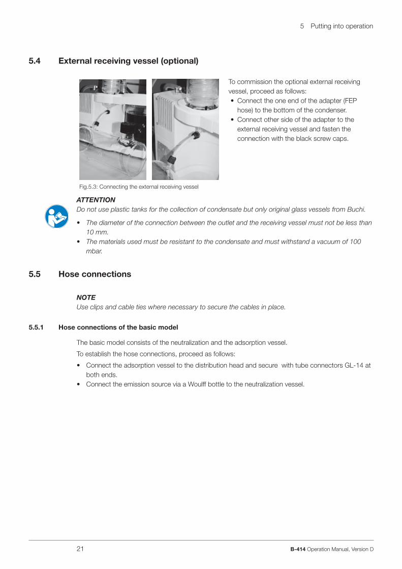
5.4 External receiving vessel (optional)
To commission the optional external receiving vessel, proceed as follows:
Connect the one end of the adapter (FEP hose) to the bottom of the condenser. Connect other side of the adapter to the external receiving vessel and fasten the connection with the black screw caps.
•
•
Fig.5.3: Connecting the external receiving vessel
ATTENTIONDo not use plastic tanks for the collection of condensate but only original glass vessels from Buchi.
The diameter of the connection between the outlet and the receiving vessel must not be less than 10 mm. The materials used must be resistant to the condensate and must withstand a vacuum of 100 mbar.
5.5 Hose connections
NOTEUse clips and cable ties where necessary to secure the cables in place.
5.5.1 Hose connections of the basic model
The basic model consists of the neutralization and the adsorption vessel.
To establish the hose connections, proceed as follows:
Connect the adsorption vessel to the distribution head and secure with tube connectors GL-14 at both ends.Connect the emission source via a Woulff bottle to the neutralization vessel.
•
•
•
•

5 Putting into operation
22 B-414 Operation Manual, Version D
3
2
1
45
� Neutralization stage� Connection of the neutralization vessel� Adsorption vessel
� Distribution head� Silencer
Fig. 5.4: Hose connections of the basic model
5 Putting into operation
23 B-414 Operation Manual, Version D
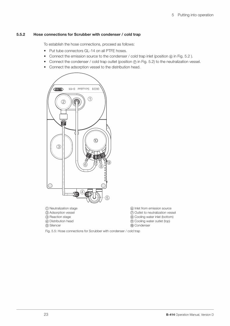
5.5.2 Hose connections for Scrubber with condenser / cold trap
To establish the hose connections, proceed as follows:
Put tube connectors GL-14 on all PTFE hoses.Connect the emission source to the condenser / cold trap inlet (position � in Fig. 5.2 ).Connect the condenser / cold trap outlet (position � in Fig. 5.2) to the neutralization vessel.Connect the adsorption vessel to the distribution head.
12
3
4
5
6 78
9
10
� Neutralization stage� Adsorption vessel� Reaction stage� Distribution head� Silencer
� Inlet from emission source� Outlet to neutralization vessel� Cooling water inlet (bottom) Cooling water outlet (top) Condenser
Fig. 5.5: Hose connections for Scrubber with condenser / cold trap
••••

5 Putting into operation
24 B-414 Operation Manual, Version D
5.5.3 Hose connections for Scrubber with condenser / cold trap and reaction vessel
To establish the hose connections, proceed as follows:
Put tube connectors GL-14 on all PTFE hoses.Connect the emission source to the condenser / cold trap inlet (position � in Fig. 5.3 ).Connect the condenser / cold trap outlet (position � in Fig. 5.3) to the neutralization vessel.Connect the adsorption vessel to the top of the reaction tubelet.Connect the reaction tubelet (connection at the front) to the distribution head
3
2 1
6 7
45
98
10
� Neutralization stage� Adsorption vessel� Reaction stage� Distribution head� Silencer
� Inlet from emission source� Outlet to neutralization vessel� Cooling water inlet (bottom) Cooling water outlet (top) Condenser
Fig. 5.6: Hose connections for Scrubber with condenser / cold trap and reaction vessel
•••••

5 Putting into operation
25 B-414 Operation Manual, Version D
5.6 Electrical connections
ATTENTIONMake sure that the voltage on the socket corresponds to the voltage given on the type plate of the instrument.
Always connect the instrument to an earthed socket. External connections and extension cables must be provided with an earthed conductor lead (3-pole couplings, cable or plug equipment) as the mains lead has a molded plug, thus avoiding risks due to inadvertent defective wiring.
Make sure that no electric sparks form in the instrument or its surroundings as they might damage the instrument.
Connect the Scubber B-414 to the mains with the power cord contained in the scope of delivery. To start the Scrubber automatically at the same time the digestion process starts, connect it to the Control Unit B-436, to a Digest System K-437 or to a Digest Automat K-438 with the optional connec-tion cable.
5.7 Preparing washing solutions
ATTENTIONAlways wear personal protective equipment such as protective eye goggles, protective clothing and gloves when working with washing solutions.
5.7.1 Washing solutions for acidic vapors and gases
Sodium hydroxide 8-10 %, max. 20 %Sodium carbonate
dissolve 600 g Na2CO3 in 3 l distilled warm water, ordissolve 1.7 kg Na2CO3 · 10H2O in 3 l distilled warm water
5.7.2 Washing solutions for alkaline vapors and gases
Hydrochloric acid, max. 15%Sulphuric acid, max. 20%
Depending on the area of application, it is recommended to use different washing solutions or concen-trations. The B-414 Scrubber is supplied ex works with a lye-resistant lip gasket. For operating with acid washing solutions, an acid-resistant lip gasket should be used.
5.7.3 Color indicator
A color indicator is added to the washing solution to assess its washing power visually as well.We recommend to use 100 mg of color indicator for 3 l of washing solution.Bromothymol blue serves as a stan dard indicator. The transition area here is between pH 6.0 to 7.6. Thus the fresh solution has a blue color while the neutralized or acidic solution has an orange yellowish color.Depending on the application purpose, other suitable color indicators should be used.
••
––
••

5 Putting into operation
26 B-414 Operation Manual, Version D
5.8 Filling up the prepared washing solution
To fi ll up the washing solution, proceed as follows:
Remove the adsorption vessel � by gently pulling it upwards.Loosen the tube connector GL-14 � at the neutralization vessel and pull off the hose.Remove the protective cover � with the protective shield.Remove the protective disc with the washing insert � from the neutralization vessel. Carefully pour the washing solution into the washing vessel and fi ll up to the wavy maximum fi lling mark.Reassemble the instrument in the reverse order.
1
2
3
45
� Adsorption vessel� Nut GL-14� Protective cover with protective shield
� Washing insert� ON/OFF switch
Fig. 5.7: Filling up the washing solution
NOTEFor information on how and when to exchange the washing solution, see chapter 7.6
•••••
•

6 Operation
27 B-414 Operation Manual, Version D
6 Operation
This chapter gives examples of typical instrument applications and instructions on how to operate the instrument properly and safely.
WARNINGRisk of injury.
Never operate the instrument when glassware is damaged.
ATTENTIONSwitch on the B-414 before a connected instrument produces gases.
6.1 Typical applications
Table 6-1: Typical applicationsGases and vapors Chemical formula Neutralization (stage 2) Specifi c reactins (stage 4)
Kjeldahl digestions SO2, H2SO4 saturated soda / NaOH 8 - 10 % (max. 20 %)
Sulfur dioxide SO2 saturated soda / NaOH 8 - 10 % (max. 20 %)
Sulfuryl chloride SO2Cl2 NaOH 8 - 10 % (max. 20 %)
Hydrochloric or hydro-bromic acids
HCI, HBr NaOH 8 - 10 % (max. 20 %)
Thionyl chloride SOCl2 NaOH 8 - 10 % (max. 20 %)
Cyanuric chloride C3N3Cl3 NaOH 8 - 10 % (max. 20 %)
Carbonic acid chloride R-COCI NaOH 8 - 10 % (max. 20 %)
Phosgene COCI2 NaOH 8 - 10 % (max. 20 %)
Ammonia NH3 HCI max. 15 % / H2SO4 max. 20 %
Nitrous oxides (nitrous gases)Nitric acid / aqua regia
NOX NaOH 20 % FESO4 saturated
Chlorine, bromine, iodine Cl2, Br2, J2 NaOH 8 - 10 % (max. 20 %) FESO4 saturated
Thiophenols Ar-SH NaOH 8 - 10 % (max. 20 %) KMnO4 saturated
Thioalcohols, mercaptan R-SH NaOH / javelle water KMnO4 saturated
Hydrogen sulphide H2S NaOH 8 - 10 % (max. 20 %) KMnO4 saturated
Carbon disulphide CS2 NaOH 8 - 10 % (max. 20 %) KMnO4 saturated
Prussic acid HCN NaOH 8 - 10 % (max. 20 %) KMnO4 saturated
•

6 Operation
28 B-414 Operation Manual, Version D
6.2 Operation
1
2
Switch on the power switch �. Make sure that the cooling water fl ow rate does not exceed 60 l/h. The suction performance can be regulated during operation by drilling a 0.1 - 0.3 mm wide hole in the screw cap GL-14 � (e.g. when samples are getting dry). Carry out a functional test as described in chapter 7.10.
••
•
•
Fig. 6.1.: Operation

7 Maintenance and repairs
29 B-414 Operation Manual, Version D
7 Maintenance
This chapter gives instructions on all maintenance work to be performed in order to keep the instru-ment in good working condition.
WARNINGElectrical hazard:
Prior to all maintenance work on the instrument switch off the power supply and remove all sources of fl ammable vapor.
ATTENTIONAlways wear personal protective equipment such as protective eye goggles, protective clothing and gloves when maintaining the instrument.
7.1 Housing
Check the housing for defects (switches, plugs) and clean it regularly with a damp cloth.
ATTENTIONNever use solvents as cleaning agents as these might damage the instrument.
7.2 Glass parts
The glass parts can be taken out and cleaned with commercially available cleaning agents or in an ultrasonic bath. After the glass parts have been cleaned and fully dried, check each part visually for cracks, scratches and for any parts or sections that might have splintered off. Take out and replace any damaged glass parts.
7.3 Tubes / tube connectors
Visually examine the tube connections regularly. When tubes become cracked and brittle, replace them with new tubes.Grease all joints on the condenser side regularly to achieve optimum tightness of the system.Flush out the tubes regularly with water or ethanol.
7.4 Sealing system
ATTENTIONWhen removing and reinstalling the seals and gaskets, make sure not to damage them. Always move them perpendicularly to the axis of the glass parts and ensure no damage occurs to the sealing lip.
Never apply grease to the seals and never touch them with sharp object, otherwise they will get damaged.
•

7 Maintenance and repairs
30 B-414 Operation Manual, Version D
7.4.1 Cleaning the seals
To prolong the lifetime of the seals, rinse them regularly with water, especially if working with crystalline products. Afterwards, dry them with a solft cloth. To remove the seals, see Fig. 7.1.
7.4.2 Replacing the seals
Seals are subject to wear and tear, thus you should check them regularly and replace them, if neces-sary, e.g. if they do not pass the functional test described in chapter 7.8 anymore.We recommend to replace the seals as follows:
Table 8-1: General malfunction and their remedyPosition in Fig. 9.1 Order no. Description Replacing interval
-- 40029 Set of seals EPDM for tube connectors once a year
8 37928 O-ring to adapter (37777) once a year
13 03575 Gasket SVL 42 x 30 PTFE once a year
17 03576 Gasket SVL 22 x 16 PTFE once a year
19 38225 Hose seal once a year
23 37873 Seal for receiving vessel once a year
34 37925 Gasket ring once a year
38 37871 Silencer unit once a year
7.5 Washing insert
The washing insert must be cleaned from time to time and the lip gasket must be replaced when brittle.
12
3
2
4
5
6 7
� Nut M20� Swirl disc� Spacer tube� Swirl disc holder
� Lip gasket� Protective disc� Tube connector adapter M20 GL-14
Fig. 7.1. Exploded view of the washing insert

7 Maintenance and repairs
31 B-414 Operation Manual, Version D
To (re)assemble the washing insert, proceed as follows:
Insert the lip gasket � into the protective disc �.Place the protective disc � on the swirl disc holder �. Screw on the adapter � and tighten it.Insert the fi rst swirl disc � .Insert the spacer tube �. Insert the second swirl disc �.Screw the washing insert into the adapter �. Introduce the washing insert into the neutralisation vessel.Put on the protective disc.Put on the protective cover with shield and center the neutralization vessel.
7.6 Washing solution
Used washing solutions may impair the functionality of the B-414 Scrubber especially in the range of the neutra lization point as a result of strong foaming. Changing the washing solution in appropriate time (when the color indicator ongoes a color change) keeps the adsorption stage and/or reaction stage from getting soiled and pre vents the possibility of the pump getting damaged. For a discription of how to prepare and fi ll up the washing solution, see chapter 5.7.
NOTEMake sure to dispose of the used washing solution according to your laboratory guidelines.
7.7 Pump
4 3
2
1
To fl ush the pump, proceed as follows: Take off the silencer � and fl ush out the pump with distilled water � through the secondary air valve �. Switch on the instrument and collect the waste water in a suitable vessel �.
•
•
Fig. 7.2: Flushing the pump
••••••••••

7 Maintenance and repairs
32 B-414 Operation Manual, Version D
7.8 Power supply fuses
1
2
To replace the power supply fuses, proceed as follows:
Pull out the power supply cable.Remove the fuse holder �. Replace the defective fuse with a new fuse � of the same type:
100 V: T 2.0 A L 250 V120 V: T 1 A L 250 V230 V: T 1 A L 250 V
Put the fuse holder back.
•••
–––
•
Fig. 7.3: Replacing the power supply fuses
7.9 Silencer
Replace the silencer once a year.
7.10 Functional test
To check whether the overpressure valve functions properly, screw off the left tube connector at the distribution head and put a fi nger on the opening. After the overpressure valve has switched, a change of sound is audible.The system is tight, when the washing solution in the neutralization vessel bubbles when the instru-ment is switched on.
7.11 Customer service
Only authorised service personnel are allowed to perform repair work on the instrument. These persons have a comprehensive technical training and knowledge of possible dangers which might arise from the instrument.Addresses of offi cial Buchi customer service offi ces are given on the Buchi website under: www.buchi.com. If malfunctions occur on your instrument or you have technical questions or applica-tion problems, contact one of these offi ces.
The customer service offers the following:
Spare part deliveryRepairsTechnical advice
•••

8 Troubleshooting
33 B-414 Operation Manual, Version D
8 Troubleshooting
This chapter helps to resume operation after a minor problem has occurred with the instrument. It lists possible occurrences, their probable cause and suggests how to remedy the problem.The troubleshooting table below lists possible malfunctions and errors of the instrument. The operator is enabled to correct some of those problems or errors by him/herself. For this, appropriate corrective measures are listed in the column “Corrective measure”.The elimination of more complicated malfunctions or errors is usually performed by a Buchi technical engineer who has access to the offi cial service manuals. In this case, please refer to your local Buchi customer service agent.
8.1 Malfunctions and their remedy
Table 8-1: General malfunction and their remedyMalfunction Possible cause Corrective measure
B-414 does not work No mains connectionFuses defective
Mains switch defective
Check whether the instrument is connected to the mainsReplace the defective fusesContact the Buchi customer service
Pump does not work Wiring defectivePump defective
Contact the Buchi customer service
Fumes are not exhausted during extraction (Scrubber suction capacity too weak)
Suction system leakingHose bentAdsorption vessel cloggedWashing solution dirtyAdsorbents cloggedPump dirtySilencer unit cloggedOverpressure valve dirty
Tighten the tube connectionsCheck the hosesCheck the adsorption vesselExchange the washing solutionRenew the adsorbentsClean the pumpReplace the silencer unitContact the Buchi customer service
Fumes are exhausted too fast during extraction (Scrubber suction capacity too strong)
Suction system clogged
Adsorbents cloggedSilencer unit defectiveOverpressure valve defective
Check all stages and the connected digestion unit as wellExchange the adsorbentsReplace the silencer unitContact the Buchi customer service
Washing solution turns yellow Washing solution dirty Exchange the washing solution

9 Shutdown, storage, transport and disposal
34 B-414 Operation Manual, Version D
9 Shutdown, storage, transport and disposal
This chapter instructs how to shut down the instrument, how to pack it for storage or transport, and specifi es the storage and shipping conditions.
9.1 Storage and transport
WARNINGBiohazard:
Remove all dangerous substances from the instrument and clean it thoroughly.
Store and transport the instrument in its original packaging.
9.2 Disposal
To dispose of the instrument in an environmentally friendly manner, a list of materials is given in chapter 3. This helps to ensure that the components are separated and recycled correctly. Make especially sure to dispose of the gas springs appropriately.Please follow valid regional and local laws concerning disposal.
•

10 Spare parts
35 B-414 Operation Manual, Version D
10 Spare parts
This chapter lists spare parts, accessories, and options including their ordering information.Order the spare parts from Buchi. Always state the product designation and the part number when ordering spare parts.Use only genuine Buchi consumables and genuine spare parts for maintenance and repair to assure good system performance and reliability. Any modifi cations to the spare parts used are only allowed with the prior written permission of the manufacturer.
10.1 Spare parts on the exploded instrument view
4
3
1
2
6
7
25
12
38
32
29
34
33
36
35
26
17
19
9
10119
30
39
161514
13
22
2324
28
21
5
27
8
18
31
20
37
Fig. 10.1: Spare parts on the exploded instrument view

10 Spare parts
36 B-414 Operation Manual, Version D
Table 10-1: Spare parts on the exploded instrument view
Position Product Order
number
Position Product Order number
1 Protective shield 37820 20 Hose adsorption / pump 37885
2 Neutralization vessel 37786 21 Condenser complete, including: 38022
3 Lip gasket lye-resistant EPDM 37874 22 - Spring ring 37872
4 Lip gasket acid-resistant FPM 38064 23 - Gasket 37873
5 Swirl disc 37821 24 - Holder ring 36709
6 Set of 4 tube connectors with cap bent FPM
40295 25 Receiving vessel, 1.2 l 37776
7 Adapter for GL-14 37777 26 Hose condenser / washing solution 37888
8 O-ring to adapter (37777) 37928 27 Cold trap 37781
9 Screw cap GL-14 (set of 10) 41956 28 O-ring FPM for cold trap 38067
- Set of seals EPDM for tube connectors (set of 10)
40029 29 Trap unit for cold trap 37782
10 Hose seal 38225 30 Connector GL-14 straight 37642
11 Screw cap GL-14 40624 31 Introduction tube assembly 37778
12 Adsorption vessel 37774 32 Reaction vessel, 1.0 l 37797
13 Gasket SVL 42 x 30 PTFE 03575 33 Screw cap SVL 42 03551
14 Adapter complete for adsorption vessel
37971 34 Gasket ring 37925
15 O-ring 47.2 for adsorption vessel 37857 35 Hose adsorption / reaction 37887
16 O-ring 39.7 for adsorption vessel 38068 36 Hose reaction / pump 37886
17 Gasket SVL 22 x 16 PTFE 03576 37 Condensate drain 37785
18 Adapter SVL 22 / GL14, complete 37972 38 Silencer unit 37871
19 Seal for FEP tube 38225 39 Distribution head, complete 37952
10.2 Miscellaneous
Table 10-2: MiscellaneousProduct Order number
Set of sealings FPM (10 pieces) 40040
Axial fl ow fan B-414 38026

11 Declarations and requirements
37 B-414 Operation Manual, Version D
11 Declarations and requirements
11.1 FCC requirements (for USA and Canada)
English:
This equipment has been tested and found to comply with the limits for a Class A digital device, pursuant to both Part 15 of the FCC Rules and the radio interference regulations of the Canadian Department of Communications. These limits are designed to provide reasonable protection against harmful interference when the equipment is operated in a commercial environment.This equipment generates, uses and can radiate radio frequency energy and, if not installed and used in accordance with the instruction manual, may cause harmful interference to radio communications. Operation of this equipment in a residential area is likely to cause harmful interference in which case the user will be required to correct the interference at his own expense.
Français:
Cet appareil a été testé et s'est avéré conforme aux limites prévues pour les appareils numériques de classe A et à la partie 15 des réglementations FCC ainsi qu’à la réglementation des interférences radio du Canadian Department of Communications. Ces limites sont destinées à fournir une protec-tion adéquate contre les interférences néfastes lorsque l’appareil est utilisé dans un environnement commercial.Cet appareil génère, utilise et peut irradier une énergie à fréquence radioélectrique, il est en outre susceptible d’engendrer des interférences avec les communications radio, s’il n’est pas installé et utilisé conformément aux instructions du mode d’emploi. L’utilisation de cet appareil dans les zones résidentielles peut causer des interférences néfastes, auquel cas l’exploitant sera amené à prendre les
dispositions utiles pour palier aux interférences à ses propres frais.

11 Declarations and requirements
38 B-414 Operation Manual, Version D
11.2 Declaration of conformity
We BÜCHI Labortechnik AGdo hereby declare on our responsibility that the product:
Scrubber B-414
which is the object of this certifi cation, is in accordance with the following norms:
EN 61010-1:2001 (~ IEC 61010-1) Safety requirements for electrical equipment for measurement, control, and laboratory usePart 1: General requirements
EN 55011:1998 + A1:1999 (IEC/CISPR 11:1997, modifi ed + A1:1999) Industrial, scientifi c and medical (ISM) radio-frequency equipment - Radio disturbance characteristics - Limits and methods of measurement
EN 60335-1:2002: Household and similar electrical appliances - Safety - Part 1: General requirements
EN 6100-3-2:2000 Limits for harmonic current emissions
EN 6100-3-3:2000 Limitations of voltage fl uctuations and fl icker
In accordance with the regulations of the EU guidelines
73/23/EEC (electrical operating equipment/low-voltage guidelines)89/336/EEC (electromagnetic compatibility)
Flawil, 12.01.06BÜCHI Labortechnik AGMeierseggstrasse 40PostfachCH-9230 Flawil 1Switzerland Tel.: +41 (0)71 394 63 63 Guido Worch Fax: +41 (0)71 394 65 65 Quality [email protected]


BÜCHI Labortechnik AGCH-9230 Flawil 1 / SwitzerlandT +41 71 394 63 63 F +41 71 394 65 65 096701
www.buchi.com Quality in your hands