extron mlm-wb+ user guide, rev. e
TRANSCRIPT

User Guide
MLM-WB+
Architectural Mounting Frames
Lockable Metal Wall Box
68-609-01 Rev. E04 13
Safety Instructions • English
WARNING: This symbol, , when used on the product, is intended to alert the user of the presence of uninsulated dangerous voltage within the product’s enclosure that may present a risk of electric shock.
ATTENTION: This symbol, , when used on the product, is intended to alert the user of important operating and maintenance (servicing) instructions in the literature provided with the equipment.
For information on safety guidelines, regulatory compliances, EMI/EMF compatibility, accessibility, and related topics, see the Extron Safety and Regulatory Compliance Guide, part number 68-290-01, on the Extron website, www.extron.com.
Instructions de sécurité • Français
AVERTISSEMENT: Ce pictogramme, , lorsqu’il est utilisé sur le produit, signale à l’utilisateur la présence à l’intérieur du boîtier du produit d’une tension électrique dangereuse susceptible de provoquer un choc électrique.
ATTENTION: Ce pictogramme, , lorsqu’il est utilisé sur le produit, signale à l’utilisateur des instructions d’utilisation ou de maintenance importantes qui se trouvent dans la documentation fournie avec le matériel.
Pour en savoir plus sur les règles de sécurité, la conformité à la réglementation, la compatibilité EMI/EMF, l’accessibilité, et autres sujets connexes, lisez les informations de sécurité et de conformité Extron, réf. 68-290-01, sur le site Extron, www.extron.fr.
Sicherheitsanweisungen • Deutsch
WARNUNG: Dieses Symbol auf dem Produkt soll den Benutzer darauf aufmerksam machen, dass im Inneren des Gehäuses dieses Produktes gefährliche Spannungen herrschen, die nicht isoliert sind und die einen elektrischen Schlag verursachen können.
VORSICHT: Dieses Symbol auf dem Produkt soll dem Benutzer in der im Lieferumfang enthaltenen Dokumentation besonders wichtige Hinweise zur Bedienung und Wartung (Instandhaltung) geben.
Weitere Informationen über die Sicherheitsrichtlinien, Produkthandhabung, EMI/EMF-Kompatibilität, Zugänglichkeit und verwandte Themen finden Sie in den Extron-Richtlinien für Sicherheit und Handhabung (Artikelnummer 68-290-01) auf der Extron-Website, www.extron.de.
Instrucciones de seguridad • Español
ADVERTENCIA: Este símbolo, , cuando se utiliza en el producto, avisa al usuario de la presencia de voltaje peligroso sin aislar dentro del producto, lo que puede representar un riesgo de descarga eléctrica.
ATENCIÓN: Este símbolo, , cuando se utiliza en el producto, avisa al usuario de la presencia de importantes instrucciones de uso y mantenimiento recogidas en la documentación proporcionada con el equipo.
Para obtener información sobre directrices de seguridad, cumplimiento de normativas, compatibilidad electromagnética, accesibilidad y temas relacionados, consulte la Guía de cumplimiento de normativas y seguridad de Extron, referencia 68-290-01, en el sitio Web de Extron, www.extron.es.
Chinese Simplified(简体中文)
警告: 产品上的这个标志意在警告用户该产品机壳内有暴露的危险
电压,有触电危险。
注意: 产品 上 的 这个标 志意在 提 示用户设备 随 附的用户手 册 中有 重要的操作和维护(维修)说明。
关于我们产品的安全指南、遵循的规范、EMI/EMF 的兼容性、无障碍
使用的特性等相关内容,敬请访问 Extron 网站 www.extron.cn,参见 Extron
安全规范指南,产品编号 68-290-01。
Chinese Traditional(繁體中文)
警告: 若產品上使用此符號,是為了提醒使用者,產品機殼內存在著
可能會導致觸電之風險的未絕緣危險電壓。
注意 若產品上使用此符號,是為了提醒使用者。
有關安全性指導方針、法規遵守、EMI/EMF 相容性、存取範圍和相關主題的詳細資訊,請瀏覽 Extron 網站:www.extron.cn,然後參閱《Extron 安全性與法規
遵守手冊》,準則編號 68-290-01。
Japanese
警告:この記号 が製品上に表示されている場合は、筐体内に絶縁されて いない高電圧が流れ、感電の危険があることを示しています。
注意:この記号 が製品上に表示されている場合は、本機の取扱説明書に 記載されている重要な操作と保守(整備)の指示についてユーザーの
注意を喚起するものです。
安全上のご注意、法規厳守、EMI/EMF適合性、その他の関連項目に ついては、エクストロンのウェブサイトwww.extron.jpより
『Extron Safety and Regulatory Compliance Guide』 (P/N 68-290-01) をご覧ください。
Korean
경고: 이 기호 , 가 제품에 사용될 경우, 제품의 인클로저 내에 있는 접지되지 않은 위험한 전류로 인해 사용자가 감전될 위험이 있음을 경고합니다.
주의: 이 기호 , 가 제품에 사용될 경우, 장비와 함께 제공된 책자에 나와 있는 주요 운영 및 유지보수(정비) 지침을 경고합니다.
안전 가이드라인, 규제 준수, EMI/EMF 호환성, 접근성, 그리고 관련 항목에 대한 자세한 내용은 Extron 웹 사이트(www.extron.co.kr)의 Extron 안전 및 규제 준수 안내서, 68-290-01 조항을 참조하십시오.
Safety Instructions
Inside front cover

FCC Class A NoticeThis equipment has been tested and found to comply with the limits for a Class A digital device, pursuant to part 15 of the FCC rules. The Class A limits provide reasonable protection against harmful interference when the equipment is operated in a commercial environment. This equipment generates, uses, and can radiate radio frequency energy and, if not installed and used in accordance with the instruction manual, may cause harmful interference to radio communications. Operation of this equipment in a residential area is likely to cause interference; the user must correct the interference at his own expense.
NOTE: For more information on safety guidelines, regulatory compliances, EMI/EMF compatibility, accessibility, and related topics, see the “Extron Safety and Regulatory Compliance Guide” on the Extron website.
Copyright© 2013 Extron Electronics. All rights reserved.
TrademarksAll trademarks mentioned in this guide are the properties of their respective owners.
The following registered trademarks(R), registered service marks(SM), and trademarks(TM) are the property of RGB Sys-tems, Inc. or Extron Electronics:
Registered Trademarks (®)
AVTrac, Cable Cubby, CrossPoint, eBUS, EDID Manager, EDID Minder, Extron, Flat Field,GlobalViewer, Hideaway, Inline, IP Intercom, IP Link, Key Minder, LockIt, MediaLink, PoleVault, PowerCage, PURE3, Quantum, SoundField, System Integrator, TouchLink, V-Lock, VersaTools, VN-Matrix, VoiceLift, WallVault, WindoWall
Registered Service Mark(SM) : S3 Service Support Solutions
Trademarks (™)
AAP, AFL (Accu-Rate Frame Lock), ADSP (Advanced Digital Sync Processing), AIS (Advanced Instruction Set), Auto-Image, CDRS (Class D Ripple Suppression), DDSP (Digital Display Sync Processing), DMI (Dynamic Motion Interpolation), Driver Configurator, DSP Configurator, DSVP (Digital Sync Validation Processing), FastBite, FOXBOX, IP Intercom HelpDesk, MAAP, MicroDigital, ProDSP, QS-FPC (QuickSwitch Front Panel Controller), Scope-Trigger, SIS, Simple Instruction Set, Skew-Free, SpeedMount, SpeedNav, SpeedSwitch, Triple-Action Switching, XTP, XTP Systems, XTRA, ZipCaddy, ZipClip

Conventions Used in this Guide
Notifications the following are used:
WARNING: A warning indicates a situation that has the potential to result in death or severe injury.
CAUTION: A caution indicates a situation that may result in minor injury.
ATTENTION: Attention indicates a situation that may damage or destroy the product or associated equipment.
NOTE: A note draws attention to important information.
Specifications Availability
Product specifications are available on the Extron website, www.extron.com.

vMLM-WB+ • Contents
Contents
Introduction ................................................... 1
About this Guide................................................ 1About the MLM-WB+ ........................................ 1Features Diagram .............................................. 2
Installation ..................................................... 3
Installation Overview ......................................... 3Accessibility Requirements ............................... 4
UL Requirements ........................................... 4ADA Requirements ........................................ 4Recommended Installation ............................ 6
Components, Hardware, and Required Tools ................................................................. 7
Main MLM-WB+ Components ...................... 7Included Mounting Hardware ........................ 7Required Tools ............................................... 8
Adjusting the Door Angle .................................. 8
Mounting the MLM-WB+ ................................... 9Selecting a Mounting Location ...................... 9Mounting the MLM-WB+ on a Masonry Wall ............................................................... 9
Mounting the MLM-WB+ on a Nonmasonry Wall ....................................... 11
Routing Cables into the MLM-WB+ ................ 13Installing the Junction Box .......................... 13Installing AV and Control Cables ................. 14
Installing Equipment ........................................ 15Installing and Cabling Equipment in the 2U Rack Enclosure ..................................... 15
Installing and Cabling Equipment in the 4U Rack Enclosure ..................................... 16
Testing the Installation ..................................... 18Completing the Installation.............................. 18Adjusting the Door Lock .................................. 20Ordering Additional or Replacement Keys ...... 20

MLM-WB+ • Contents vi

MLM-WB+ • Introduction 11
Introduction
This section gives an overview of the capabilities of the Extron MLM-WB+ wall box and provides a diagram of its features. The following topics are covered:
• About this Guide
• About the MLM-WB+
• Features Diagram
About this Guide
This guide contains a description and specifications of the MLM-WB+ wall box and provides installation instructions.
About the MLM-WB+
The Extron MLM-WB+ is a locking metal wall box with two enclosures for mounting Extron controllers and audio-video (AV) equipment.
The upper, 2U rack enclosure can hold Extron mounting frames and faceplates for mounting Architectural Adapter Plates (AAPs) and control pads such as the MediaLink 226 IP. Alternatively, Extron quarter-rack width products that are 3 inches (7.6 cm) deep can be mounted in this space using an Extron 3.5 inches deep rack shelf.
The lower, 4U rack enclosure can hold a VCR, DVD player, rack-mountable switcher, or other rack-mountable equipment. The top of the enclosure also provides a stable platform for a laptop or other small, portable device.
The MLM-WB+ can be installed on masonry walls, walls with wood or aluminum studs, and walls with a combination of solid and hollow areas.
WARNINGS: Risk of Severe Bodily Injury:
• Do not sit on or lean against the door or 4U rack enclosure.
• When properly installed, the open 4U door can hold up to 150 pounds (68 kg). For safety considerations, Extron recommends that no more than 15 pounds (7 kg) be placed on top of the open door.

MLM-WB+ Series • Introduction 2
Features Diagram
Figure 1 shows the parts of the MLM-WB+.
PROJECTOR1
2
3
4
5
6
VOLUMECONFIG
IR
PC
AUX
VIDEO
DVD
VCR
LAPTOP
AUTO
IMAGE
MUTE
ON
OFF
MLC 226 IP L
DVD-RW/-R RECORDING
Precision Cinema Progressive
MLS 406MA
MediaLink Switcher
CONTROL
PEAK
CLIP
SIGNAL
INPUT SELECT
1
2
3
4
5
6
DVD Player
Cam Lock
4U Rack Enclosure
MediaLink Switcher
MLC 226 IP L AAPs
UCM RAAP
Figure 1. The MLM-WB+ Wall Box

MLM-WB+ • Installation 3
Installation
This section contains instructions for installing the MLM-WB+ and for connecting cables to equipment in the wall box. The following topics are discussed:
• Installation Overview
• Accessibility Requirements
• Components, Hardware, and Required Tools
• Adjusting the Door Angle
• Mounting the MLM-WB+
• Routing Cables into the MLM-WB+
• Installing Equipment
• Testing the Installation
• Completing the Installation
• Adjusting the Door Lock
• Ordering Additional or Replacement Keys
Installation Overview
WARNINGS: Risk of Severe Bodily Injury:
• Do not sit on or lean against the door or the 4U rack enclosure.
• For safety considerations, Extron recommends that no more than 15 pounds (7 kg) be placed on top of the open door.
ATTENTION: Potential Damage to Property: All installation and service procedures should be performed by a qualified Extron installer or an electrician. Extron is not responsible for equipment failure or damage occurring as a result of an improper installation.
NOTE: Contact a contractor or hardware specialist for assistance with the installation. Your installation may require additional hardware beyond what Extron provides with the MLM-WB+.
Identify components and mounting hardware for the MLM-WB+ and obtain the tools required for installation (see Components, Hardware, and Required Tools on page 7).
1. Select the installation site. On nonmasonry walls, the MLM-WB+ must be attached to at least one stud. The recommended installation suggests that the wall box be attached to two wall studs or to a concrete or masonry wall.
2. Mount the outer enclosure onto the wall, and route power cables of the electrical devices into the junction box inside the MLM-WB+.
3. Wire power cables to the duplex receptacles, and secure the receptacles and junction box cover to the junction box.

MLM-WB+ • Installation 4
4. Route the audio, video, control, and power cables of the electrical devices through the small rectangular openings on top of the MLM-WB+. Remove the left and right side panels and continue routing these cables to the lower part of the enclosure (see Routing Cables into the MLM-WB+ on page 13).
5. Install all devices into the MLM-WB+ 2U and 4U rack enclosures. To do this, perform the setup procedure (if applicable) for each AV device to be installed and then connect power and AV cables to all equipment (see Installing Equipment on page 15).
6. Test all installed equipment. Make adjustments to settings and cabling as needed. Be sure to disconnect power from all electrical devices before making wiring changes.
WARNING: Risk of Electric Shock. Disconnect power from the computer, all input and output devices, and any controllers before adjusting the wiring.
7. Secure all equipment in the 2U and 4U rack enclosures.
Accessibility Requirements
Keep the following safety and accessibility requirements in mind when choosing an installation location and method.
UL Requirements
The Underwriters Laboratories (UL) requirements listed below pertain to the installation of an MLM-WB+ wall box.
• Power supplies used with devices such as an MLC must be secured in the MLM-WB+ with the flat side down.
• You must use a UL-listed junction box.
NOTE: The UL-listed electrical box (junction box) is included with the MLM-WB+.
• This unit must be installed in accordance with the National Electrical Code and with all local codes.
NOTE: For specific and location-based requirements, contact UL (1-877-ULHELPS or www.ul.com) or a UL specialist.
ADA Requirements
The following Americans with Disabilities Act (ADA) requirements pertain to the installation of the MLM-WB+ into a masonry or non-masonry wall. ADA compliance is a legal requirement in most of the U.S., and is intended to ensure safety for the disabled while they are moving about public places. For specific requirements in your area, contact an ADA specialist (see the note below for contact information).
NOTE: For specific and location-based requirements, contact the ADA (1-800-514-0301 or www.ada.gov) or an ADA specialist.

MLM-WB+ • Installation 5
The MLM-WB+ must be mounted with the bottom edge at a maximum of 27 inches (68.6 cm) above the finished floor. This regulation was created to ensure that the blind or visually impaired, using a cane or guide animal, will be able to detect the MLM-WB+ without collision.
27” (68.6 cm)or lower
ExtronMLM-WB+MediaLink Wall Box
Figure 2. MLM-WB+ as a Protruding Object Along a Wall
The topmost controls of devices housed in the MLM-WB+ must be 48 inches (122 cm) or less from the finished floor. This regulation was proposed so that a person in a wheelchair has access to the controls with a maximum side reach of 48 inches (122 cm).
48" (122 cm)
ExtronMLM-WB+MediaLink Wall Box
or lower
Figure 3. Wheelchair Access to the MLM-WB+
MLM-WB+ • Installation 6
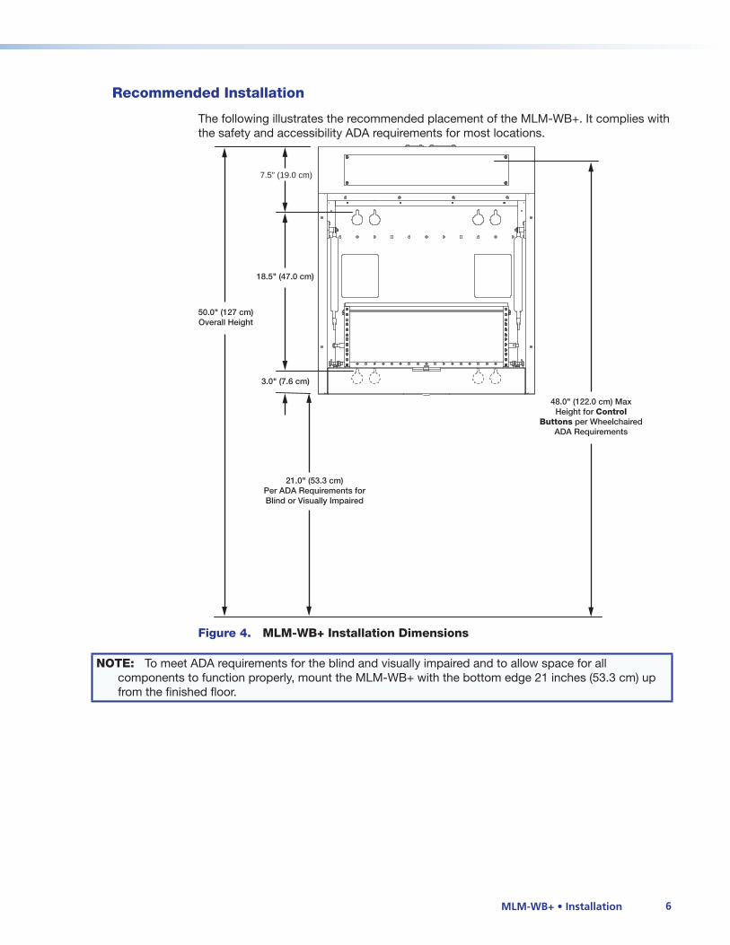
Recommended Installation
The following illustrates the recommended placement of the MLM-WB+. It complies with the safety and accessibility ADA requirements for most locations.
18.5" (47.0 cm)
3.0" (7.6 cm)
7.5" (19.0 cm)
21.0" (53.3 cm) Per ADA Requirements for Blind or Visually Impaired
50.0" (127 cm)Overall Height
48.0" (122.0 cm) MaxHeight for Control
Buttons per WheelchairedADA Requirements
Figure 4. MLM-WB+ Installation Dimensions
NOTE: To meet ADA requirements for the blind and visually impaired and to allow space for all components to function properly, mount the MLM-WB+ with the bottom edge 21 inches (53.3 cm) up from the finished floor.

MLM-WB+ • Installation 7
Components, Hardware, and Required Tools
The illustrations in this section identify the components of the MLM-WB+ and the mounting hardware provided with it. Also included is a list of tools required to perform the installation. The installation steps in this section refer to these components, hardware, and tools.
Main MLM-WB+ Components
Adjustable Clamp Brackets
Extension Damper
12" (30.5 cm) and 16" (40.6 cm)OC Spaced Mounting Slots
Cable Opening (2 per side)
Cable Tie Holes
Removable Side Panel(to access cable channel)
Clevis Bracket(for door leveling adjustment)
Rubber Stop
4U Rack Enclosure
Work Space/Equipment Cover (Max. 15 lb [7 kg])
2U Rack Enclosure
Figure 5. MLM-WB+ Main Components
Included Mounting Hardware
The following mounting hardware is included with the MLM-WB+:
(6) 1/4" x 1 3/4" Masonry Screws #40-373-01
(6) 1/4" x 1" O.D., 5/16" I.D. Metal Washers #40-376-01
(6) #14 x 1 3/4" Self-tapping Metal/Wood Screws #40-372-01
(4) 1/4-20 x 2" Pan Head Bolts #40-375-01
(4) 1/4" Kap Toggle Assemblies #40-374-01
Figure 6. Mounting Hardware
MLM-WB+ • Installation 8
Required Tools
To install the MLM-WB+ you need the following tools:
• Phillips screwdriver • Pencil
• Flat head screwdriver • 3/8-inch wrench or ratchet
• Drill with drill bits • Wire cutter
• Level
Adjusting the Door Angle
Before mounting the MLM-WB+, ensure that the door opens to a 90º angle. To adjust the door angle:
1. Set the MLM-WB+ upright on a flat surface and open the door.
CAUTION: Risk of Bodily Injury: If not properly secured in place, the MLM-WB+ can potentially fall forward.
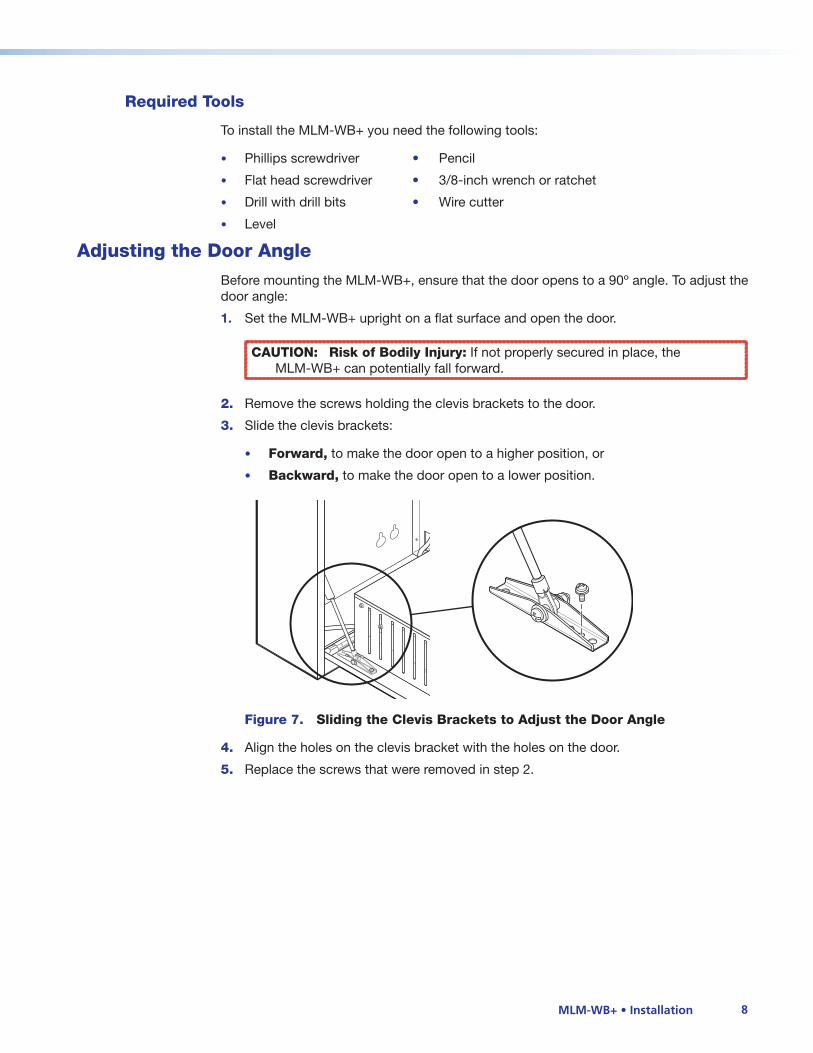
2. Remove the screws holding the clevis brackets to the door.
3. Slide the clevis brackets:
• Forward, to make the door open to a higher position, or
• Backward, to make the door open to a lower position.
Figure 7. Sliding the Clevis Brackets to Adjust the Door Angle
4. Align the holes on the clevis bracket with the holes on the door.
5. Replace the screws that were removed in step 2.

MLM-WB+ • Installation 9
Mounting the MLM-WB+
The procedures in this section enable you to securely mount the MLM-WB+ to a masonry or nonmasonry wall. These procedures assume that you have already unpacked the MLM-WB+ and installed necessary cables into the wall or conduits in conformance with local and national electrical codes and equipment size requirements.
ATTENTION: Potential Damage to Property: All installation and service procedures should be performed by a qualified Extron installer or an electrician. Extron is not responsible for equipment failure or damage occurring as a result of an improper installation.
NOTE: Review UL and ADA mounting and installation requirements (see Accessibility Requirements on page 4).
WARNING: Risk of Severe Bodily Injury. The MLM-WB+ weighs approximately 63 pounds (29 kg) without equipment installed. To avoid injury, use at least two individuals to unpack and mount the MLM-WB+, following, as a minimum, these safe lifting and moving guidelines:
• Avoid lifting with your back.
• Use both hands to hold the MLM-WB+.
• Avoid unnecessary reaching, bending, or twisting.
Selecting a Mounting Location
When determining a mounting location for the MLM-WB+, consider the following factors:
• Type of wall — This section contains installation instructions for both masonry and nonmasonry walls. In addition, the thickness of the wall and the accessibility of wall studs determine the number of mounting holes to be used and whether toggle bolts are required.
• Adequate clearance on all sides of the MLM-WB+ — Keep in mind that when fully lowered, the door extends out about 20.5 inches (52 cm) from the front of the MLM-WB+. Sufficient space is also required on each side of the MLM-WB+ to remove the side panels, to route cables, and to access the rear panel of any AV device mounted in the 2U rack enclosure.
• Proximity of the MLM-WB+ to installed cables — For example, if you plan to route cables from the wall into the opening in the back of the MLM-WB+, you should prepare the cables and position the MLM-WB+ accordingly.
Mounting the MLM-WB+ on a Masonry Wall
To mount the MLM-WB+ onto a brick, stone, or concrete wall:
1. With the help of at least one other person, hold the MLM-WB+ against the wall and use a carpentry level or similar tool as a guide for leveling the unit.
2. Mark at least six locations for masonry screws to ensure the strength and stability of the installation. As shown in figure 8 on the next page, mark four positions to line up with slotted mounting holes on the MLM-WB+ enclosure and two positions to line up with round mounting holes (indicated by + marks).
3. Set the MLM-WB+ aside.

MLM-WB+ • Installation 10
FIG_Mounting hole locations
4.
MLM-WB+ mounting 4corners.eps
Figure 8. MLM-WB+ Mounting Hole Locations (Viewed from the Front)
NOTE: To more clearly indicate where mounting holes should be marked, the rear panel of the MLM-WB+ is shown.
5. Using a masonry drill bit, drill pilot holes in the wall at the locations you marked in step 2; make the holes 1.75 inches (4.4 cm) deep.
ATTENTION: Potential Damage to Property. If you make the pilot hole too shallow, the screw head might break off while it is being fastened into the hole.
6. Install masonry screws in slotted mounting hole locations as follows:
a. Prepare the screw for installation by inserting it through a flat metal washer (1 inch [2.5 cm] outer diameter and 0.25 inch [0.6 cm] inner diameter).
b. Insert the screw and washer into one of the pilot holes on the wall.
NOTE: At this time, install only the masonry screws that line up with slotted mounting holes on the MLM-WB+.
c. Securely fasten the screw into the wall until a gap of 1/8 to 3/8 inch (3 to 9 mm) remains between the wall and the metal washer.
d. Repeat these steps until all masonry screws have been installed for slotted mounting hole locations.
7. Align the slotted mounting holes ( ) in the back of the MLM-WB+ with the screws in the wall. Move the MLM-WB+ forward over the washers and down, as shown at right.
8. Insert a masonry screw and washer through each round mounting hole on the MLM-WB+ enclosure for which you drilled a pilot hole.
9. Tighten all masonry screws to secure the unit to the wall.
+
A B
+

MLM-WB+ • Installation 11
Mounting the MLM-WB+ on a Nonmasonry Wall
NOTE: On nonmasonry walls, the MLM-WB+ must be attached to at least one stud. The recommended installation suggests that the wall box be attached to two wall studs or to a concrete or masonry wall.
1. Locate the wall studs in the area where you will install the MLM-WB+, and use a pencil to mark their locations on the wall.
2. With the help of at least one other person, hold the MLM-WB+ against the wall so that the mounting holes line up with the studs as follows:
• If two wall studs are accessible, align the slotted and round mounting holes on the back of the MLM-WB+ with the studs as shown in figure 9 (choose either option A or option B).
• If only one wall stud is accessible, align the round mounting hole in the center of the MLM-WB+ with the stud (option C in figure 9).
12" (30.5 cm)16" (40.6 cm)
Level
A B C
Figure 9. Options for Securing the MLM-WB+ to Wall Studs (View of Rear Panel as Seen from the Front)
3. Use a carpentry level or similar tool as a guide for leveling the unit.
4. When the MLM-WB+ is level and properly aligned with the studs, mark the locations of the slotted and round mounting holes on the MLM-WB+ (indicated by + marks in figure 9).
If you are mounting the MLM-WB+ to only one stud (option C in figure 9) also mark the slotted holes indicated by the four X marks to add toggle bolts to increase the stability and strength of the installation.
5. Set the MLM-WB+ aside.
6. Drill pilot holes in the wall at the locations you marked in step 4.
• If drilling into a stud, make each hole 1.75 inches (4.4 cm) deep.
• If drilling into the wall where no stud is present, make each hole through to the hollow part of the wall.

MLM-WB+ • Installation 12
7. Install a self-tapping screw and washer in each slotted mounting hole ( ) location lined up with a wall stud:
a. Prepare the screw for installation by inserting it through a flat metal washer (1 inch [2.5 cm] outer diameter and 0.25 inch [0.6 cm] inner diameter).
b. Insert the screw and washer into one of the pilot holes on the wall.
NOTE: At this time, install only screws that line up with slotted mounting holes on the MLM-WB+.
c. Securely fasten the screw into the wall until a gap of 1/8 inch to 3/8 inch (3 to 9 mm) remains between the wall and the metal washer.
d. Repeat these steps until all self-tapping screws have been installed for slotted mounting hole locations.
8. Install toggle bolts (if required) as follows:
a. While holding the plastic handle, collapse the toggle assembly and insert it into the wall through one of the pilot holes.
b. Secure the toggle assembly by sliding the plastic washer down the plastic handle into the pilot hole in the wall.
c. Using a cutting tool, cut off the plastic handle close to the plastic washer in the wall. The plastic washer creates a threaded hole for a toggle bolt.
d. Insert a pan head bolt through a metal washer, then into the threaded hole, leaving a gap of 1/8 to 3/8 inch (3 to 9 mm) between the washer and the wall.
a. b.
c. d.
Figure 10. Installing Toggle Bolts
ATTENTION: Potential Damage to Property. Install the toggle bolt by hand; do not use a power tool. A power tool may create too much pressure, causing the plastic washer of the toggle assembly to break. If this happens, the assembly will fall into the wall.
e. Repeat these steps until all toggle bolts have been installed.
MLM-WB+ • Installation 13
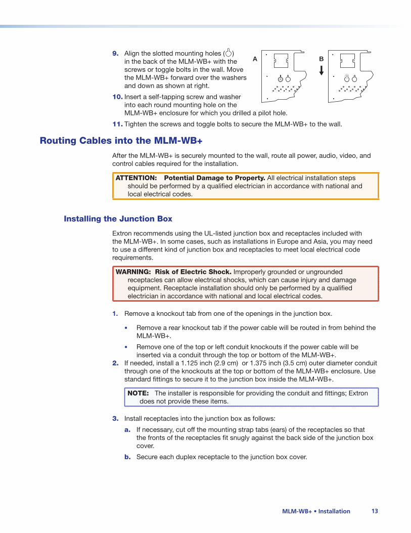
9. Align the slotted mounting holes ( ) in the back of the MLM-WB+ with the screws or toggle bolts in the wall. Move the MLM-WB+ forward over the washers and down as shown at right.
10. Insert a self-tapping screw and washer into each round mounting hole on the MLM-WB+ enclosure for which you drilled a pilot hole.
11. Tighten the screws and toggle bolts to secure the MLM-WB+ to the wall.
Routing Cables into the MLM-WB+
After the MLM-WB+ is securely mounted to the wall, route all power, audio, video, and control cables required for the installation.
ATTENTION: Potential Damage to Property. All electrical installation steps should be performed by a qualified electrician in accordance with national and local electrical codes.
Installing the Junction Box
Extron recommends using the UL-listed junction box and receptacles included with the MLM-WB+. In some cases, such as installations in Europe and Asia, you may need to use a different kind of junction box and receptacles to meet local electrical code requirements.
WARNING: Risk of Electric Shock. Improperly grounded or ungrounded receptacles can allow electrical shocks, which can cause injury and damage equipment. Receptacle installation should only be performed by a qualified electrician in accordance with national and local electrical codes.
1. Remove a knockout tab from one of the openings in the junction box.
• Remove a rear knockout tab if the power cable will be routed in from behind the MLM-WB+.
• Remove one of the top or left conduit knockouts if the power cable will be inserted via a conduit through the top or bottom of the MLM-WB+.
2. If needed, install a 1.125 inch (2.9 cm) or 1.375 inch (3.5 cm) outer diameter conduit through one of the knockouts at the top or bottom of the MLM-WB+ enclosure. Use standard fittings to secure it to the junction box inside the MLM-WB+.
NOTE: The installer is responsible for providing the conduit and fittings; Extron does not provide these items.
3. Install receptacles into the junction box as follows:
a. If necessary, cut off the mounting strap tabs (ears) of the receptacles so that the fronts of the receptacles fit snugly against the back side of the junction box cover.
b. Secure each duplex receptacle to the junction box cover.
+
A B
+

MLM-WB+ • Installation 14
Installing AV and Control Cables
This section explains how to route AV and control cables through the MLM-WB+.
NOTE: To reduce electromagnetic interference, route the AV and control cables separately from the power cables.
1. Remove the right, left, or both side panels from the MLM-WB+ by loosening the nuts on the inside of the unit and then pushing the panels out. Set the panels aside.
Loosen nutto removeside panel.
Figure 11. Removing the MLM-WB+ Side Panels
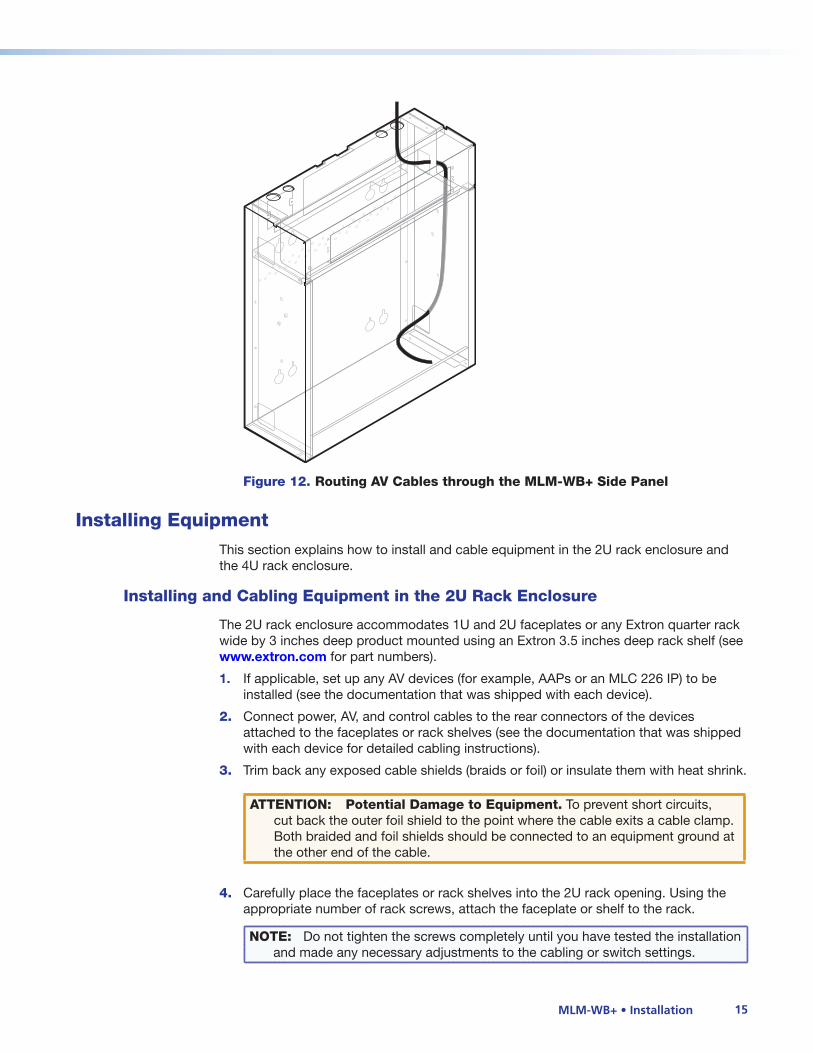
2. Feed the AV cables through the small rectangular openings in the right side panel to route cables to and from the 4U and 2U rack enclosures.
3. Route the AV and control cables through the opening in the rear panel or through the top or bottom of the enclosure through the knockout.
If you route cables through the top or bottom of the MLM-WB+, install a conduit or raceway through a knockout. Allow enough cable inside the MLM-WB+ to permit the door to open fully when cabled equipment is installed.
NOTE: The installer is responsible for providing the conduit and fittings; Extron does not provide these items.
MLM-WB+ • Installation 15
Figure 12. Routing AV Cables through the MLM-WB+ Side Panel
Installing Equipment
This section explains how to install and cable equipment in the 2U rack enclosure and the 4U rack enclosure.
Installing and Cabling Equipment in the 2U Rack Enclosure
The 2U rack enclosure accommodates 1U and 2U faceplates or any Extron quarter rack wide by 3 inches deep product mounted using an Extron 3.5 inches deep rack shelf (see www.extron.com for part numbers).
1. If applicable, set up any AV devices (for example, AAPs or an MLC 226 IP) to be installed (see the documentation that was shipped with each device).
2. Connect power, AV, and control cables to the rear connectors of the devices attached to the faceplates or rack shelves (see the documentation that was shipped with each device for detailed cabling instructions).
3. Trim back any exposed cable shields (braids or foil) or insulate them with heat shrink.
ATTENTION: Potential Damage to Equipment. To prevent short circuits, cut back the outer foil shield to the point where the cable exits a cable clamp. Both braided and foil shields should be connected to an equipment ground at the other end of the cable.
4. Carefully place the faceplates or rack shelves into the 2U rack opening. Using the appropriate number of rack screws, attach the faceplate or shelf to the rack.
NOTE: Do not tighten the screws completely until you have tested the installation and made any necessary adjustments to the cabling or switch settings.

MLM-WB+ • Installation 16
PROJECTOR1
2
3
4
5
6
VOLUMECONFIG
IR
PC
AUX
VIDEO
DVD
VCR
LAPTOP
AUTO
IMAGE
MUTEON
OFF
Extron
MLC 226 IP L
Figure 13. Installing Faceplate-mounted Equipment in the 2U Rack Enclosure
Installing and Cabling Equipment in the 4U Rack Enclosure
The 4U rack enclosure is designed to hold full-rack wide equipment such as switchers, VCRs, and DVD players.
1. Remove the top of the 4U rack enclosure by unscrewing the four screws that secure it to the enclosure, as shown below.
PROJECTOR1
2
3
4
5
6
VOLUMECONFIG
IR
PC
AUX
VIDEO
DVD
VCR
LAPTOP
AUTO
IMAGE
MUTEON
OFF
Extron
MLC 226 IP L
Figure 14. Removing the Top of the 4U Rack Enclosure
MLM-WB+ • Installation 17
2. Remove the screws attaching the adjustable clamp brackets to the inside of the enclosure. Set the brackets and cover aside.
3. Stack equipment on the door, making sure not to exceed the maximum equipment height of 5.5 inches (14.0 cm) or the maximum rack depth of 16.0 inches (40.6 cm).
ATTENTION: Potential Damage to Equipment. Be careful not to scrape the equipment against the cam lock of the door.
NOTES:
• Remove rubber feet from the bottom of any equipment you are mounting using rack ears.
• You can use custom rack shelves to mount equipment such as VCRs and DVD players in the 4U enclosure (Extron does not supply these shelves).
4. Attach power and AV cables to all equipment.
5. Trim back any exposed cable shields (braids or foil) or insulate them with heat shrink.
ATTENTION: Potential Damage to Equipment. To prevent short circuits, cut back the outer foil shield to the point where the cable exits a cable clamp. Both braided and foil shields should be connected to an equipment ground at the other end of the cable.
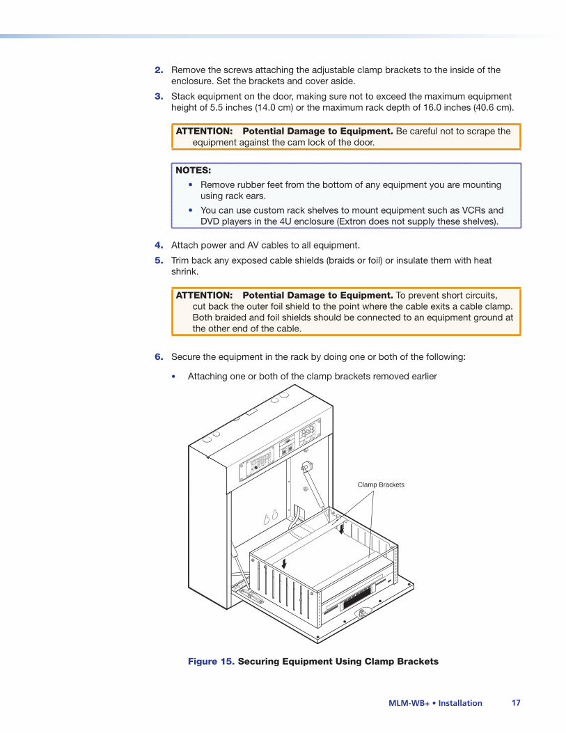
6. Secure the equipment in the rack by doing one or both of the following:
• Attaching one or both of the clamp brackets removed earlier
Clamp Brackets
PROJECTOR1
2
3
4
5
6
VOLUMECONFIG
IR
PC
AUX
VIDEO
DVD
VCR
LAPTOP
AUTO
IMAGE
MUTEON
OFF
Extron
MLC 226 IP L
Figure 15. Securing Equipment Using Clamp Brackets

MLM-WB+ • Installation 18
• Using mounting screws to secure each piece of equipment with rack mounting ears to the holes in the enclosure
SYSTEM 5 IP
PC VIDEOINPUT 5
CLIP
NORMALVOLUME AUDIO
ADJUST
SIGNAL
DISPLAY
ROOM CONTROL
INPUT SELECTION
SWSTEM
SWITCHER
CONFIG
IR
MENUNEXT
2
3
4
5/ RGB
1
LAPTOP
DVD
VCR
DESKTOP
PC 1
ROOM
RELAY3
ROOM
RELAY2
ROOM
RELAY1
OFF
ON
PROJECTOR1
2
3
4
5
6
VOLUMECONFIG
IR
PC
AUX
VIDEO
DVD
VCR
LAPTOP
AUTO
IMAGE
MUTEON
OFF
Extron
MLC 226 IP L
Figure 16. Securing Equipment with Rack Mounting Brackets (Rack Ears)
NOTE: Do not tighten the clamps or screws completely until you have tested the installation and made any needed adjustments to the cabling or switch settings.
7. Replace the top of the enclosure and use the four screws you removed in step 1 to reattach it.
Testing the Installation
Test the installation as follows:
1. Supply power to all input and output devices, the host computer, and so on.
2. Test all equipment, connections, and devices. Make adjustments to wiring, switch settings, and so on, as needed.
Completing the Installation
After you have pretested the installation and made any necessary adjustments, you can secure all equipment in the MLM-WB+.
1. Secure the equipment in the 4U rack enclosure by completely tightening the clamps or rack mounting screws.
2. Using cable ties, secure all power and AV cables to the cable guide behind the 4U rack enclosure (cut off any excess cable tie that protrudes). This provides strain relief as you open and close the door.

MLM-WB+ • Installation 19
PROJECTOR1
2
3
4
5
6
VOLUMECONFIG
IR
PC
AUX
VIDEO
DVD
VCR
LAPTOP
AUTO
IMAGE
MUTEON
OFF
Extron
MLC 226 IP L
Figure 17. Securing Cables to the Cable Guide
3. Replace the left and right side panels. Hand tighten the nuts that hold each side panel in place.
NOTE: Do not overtighten the nuts.
4. Completely tighten the mounting screws for the faceplates or rack shelves in the 2U rack enclosure.
5. Close and lock the door.
ATTENTION: Potential Damage to Property: To avoid damaging the equipment in the 4U rack enclosure, always remove CDs, DVDs, or tapes before closing the door.

MLM-WB+ • Installation 20
Adjusting the Door Lock
By default, the key to the door lock cannot be removed when the door is unlocked. To adjust the lock so that the key can be removed at any time:
1. Remove the nut, washer, and cam and set them aside.
2. Remove the cam, flip it over, and then thread it back onto the screw.
3. Replace the cam, washer, and nut and tighten securely.
Flip
Nut
Washer
Cam
Figure 18. Flipping the Cam to Adjust the Door Lock
Ordering Additional or Replacement Keys
To save our dealers time and expense, Extron directs all requests for replacement keys to our supplier, McMaster-Carr. Extron does not provide additional or replacement keys.
NOTE: Be sure to write down the MLM-WB+ serial number and the key number found on the key itself. Save these numbers in a safe place; you need them to order additional or replacements keys. Different MLM-WB+ wall boxes may have differently numbered keys.
Write these numbers below for easy access:
MLM-WB+ serial number:_________________ Key Number: _____________________
If you require additional or replacement keys for your MLM-WB+, you must purchase them through McMaster-Carr (www.mcmaster.com) directly. To do so,
1. Call McMaster-Carr customer service at 330-342-6100.
2. Provide the sales representative with item part number 1682A41.
3. Specify the unique key number inscribed on your key and the required quantity.
4. You can also purchase a master key through McMaster-Carr. Provide the sales representative with the part number 1682A15; key number Y18A.

Extron Headquarters
+1.800.633.9876(InsideUSA/CanadaOnly)
ExtronUSA-West ExtronUSA-East+1.714.491.1500 +1.919.863.1794+1.714.491.1517FAX +1.919.863.1797FAX
Extron Europe
+800.3987.6673(InsideEuropeOnly)
+31.33.453.4040+31.33.453.4050FAX
Extron Asia
+800.7339.8766(InsideAsiaOnly)
+65.6383.4400+65.6383.4664FAX
Extron Japan
+81.3.3511.7655+81.3.3511.7656FAX
Extron China
+4000.398766InsideChinaOnly
+86.21.3760.1568+86.21.3760.1566FAX
Extron Middle East
+971.4.2991800+971.4.2991880FAX
Extron Korea
+82.2.3444.1571+82.2.3444.1575FAX
Extron India
1800.3070.3777InsideIndiaOnly
+91.80.3055.3777+91.80.3055.3737FAX
© 2013ExtronElectronicsAllrightsreserved.www.extron.com
Extron WarrantyExtronElectronicswarrantsthisproductagainstdefectsinmaterialsandworkmanshipforaperiodofthreeyearsfromthedateofpurchase.Intheeventofmalfunctionduringthewarrantyperiodattributabledirectlytofaultyworkmanshipand/ormaterials,ExtronElectronicswill,atitsoption,repairorreplacesaidproductsorcomponents,towhateverextentitshalldeemnecessarytorestoresaidproducttoproperoperatingcondition,providedthatitisreturnedwithinthewarrantyperiod,withproofofpurchaseanddescriptionofmalfunctionto:
USA, Canada, South America, and Central America: Extron Electronics1001EastBallRoadAnaheim,CA92805U.S.A.
Japan: ExtronElectronics,JapanKyodoBuilding,16IchibanchoChiyoda-ku,Tokyo102-0082Japan
Europe, Africa, and the Middle East: ExtronEuropeHanzeboulevard103825PHAmersfoortTheNetherlands
China: ExtronChina686RonghuaRoadSongjiangDistrictShanghai201611China
Asia: ExtronAsia135JooSengRoad,#04-01PMIndustrialBldg.Singapore368363Singapore
Middle East: ExtronMiddleEastDubaiAirportFreeZoneF12,POBox293666UnitedArabEmirates,Dubai
ThisLimitedWarrantydoesnotapplyifthefaulthasbeencausedbymisuse,improperhandlingcare,electricalormechanicalabuse,abnormaloperatingconditions,orifmodificationsweremadetotheproductthatwerenotauthorizedbyExtron.
NOTE: Ifaproductisdefective,pleasecallExtronandaskforanApplicationEngineertoreceiveanRA(ReturnAuthorization)number.Thisbeginstherepairprocess.
USA: 714.491.1500 Europe: +31.33.453.4040Asia: +65.6383.4400 Japan: +81.3.3511.7655
Unitsmustbereturnedinsured,withshippingchargesprepaid.Ifnotinsured,youassumetheriskoflossordamageduringshipment.Returnedunitsmustincludetheserialnumberandadescriptionoftheproblem,aswellasthenameofthepersontocontactincasethereareanyquestions.
Extron Electronicsmakesnofurtherwarrantieseitherexpressedorimpliedwithrespecttotheproductanditsquality,performance,merchantability,orfitnessforanyparticularuse.InnoeventwillExtronElectronicsbeliablefordirect,indirect,orconsequentialdamagesresultingfromanydefectinthisproductevenifExtronElectronicshasbeenadvisedofsuchdamage.
Pleasenotethatlawsvaryfromstatetostateandcountrytocountry,andthatsomeprovisionsofthiswarrantymaynotapplytoyou.
Contactinformation
Warranty
Contact Information
Contents
Warranty .............................................................vContact Information ............................................v