extrusion of glass - philips bound...extrusion of glass e. roeder in recent years many new types of...
TRANSCRIPT

96 Philips tech. Rev. 32, 96-101,1971, No. 3/4
Extrusion of glass
E. Roeder
In recent years many new types of glass have become available which do not alwayslend themselves readily to the conventional methods of shaping. Increasing interest hastherefore been shown in new methods. The artiele below discusses the application ofextrusion techniques to glass. Extrusion is shown to be especially suitable for glassesthat have a strong tendency la crystallize.
ln the metal and plastics industry extrusion is nowa-days a widely used method of manufacturing rods andtubes of various profiles [11. There are two main formsof this essentially simple method: direct and indirect(or inverse) extrusion. In direct extrusion a quantity ofmaterial contained in a cylinder is subjected to pressureby a plunger or punch, which forces it through the rela-tively small aperture of a die; see jig. la. The materialis heated before extrusion to increase its plasticity. Theprofile of the bars extruded in this way is determinedby the shape of the die aperture. Tubes instead of barscan be obtained by fitting a mandrel in the die aperture
Dr. Ing. E. Roeder is with Philips Forschung slaboratorium AcehenGl11bH, Aachen, Germany.
(fig. Ib). During this process the punch and the ex-truded rod or tube move in the same direction.
In the indirect extrusion process a hollow punch isused, to which the die is fixed. Pressure on the diecauses it to move towards the material, so that thematerial is forced through the hollow punch (fig. I c).The compressed material thus flows in the directionopposite to that of the punch. There are no frictionalforces at the cylinder wall in this case, since there is norelative motion between the cylinder and the material.Although this method therefore requires less compres-sive force, the use of a hollow punch involves so manydifficulties that indirect extrusion today is employedonly in special cases.

Philips tech. Rev. 32, No. 3/4 EXTRUSION OF GLASS 97
6
6 6 D [JD D D D [J DD D D D [J tUD D D D D DtU D D D D 0DJ D D 0 [J 0D D Cl 0 Dl DDJ D D D
Q_
Fig. 1. The three types of extrusion equipment (schematic): a) for direct extrusion of rods(punch and glass rod move in the same direction), b) for direct extrusion of tubes andc) for indirect extrusion of rods (punch and rod move in opposite directions). 1 glass billet.2 punch. 3 die. 4 extruded product. 5 thermocouple (only partly visible in b; the weld hereis at the end of the hollow mandrel 7). 6 high-frequency coil for induction heating.
In the glass ind ustry extrusion is not yet a widelyused method. This is presumably because the glassesused until the present in industry have mainly beentypes that can be shaped in an economic way by theconventional methods, such as moulding, blowing, draw-ing, pressing or rolling. Recently, however, there hasbeen an increasing demand for new types of glass withspecial chemical and physical properties, and often ofunusual compositions. Extrusion lends itself better tothe shaping of such glasses than the conventionalmethods [21, and in some cases it is in fact the onlypossi bie method.
Just as with metals and plastics, extrusion of glassalso provides a simple means of producing tubes androds ofwidely different shapes and cross-sections. Sometypical extruded glass products are shown in the titlephotograph.
Which types of glass are most suitable for extrusion?
Short glasses
In the working of glass, one of the most importantproperties is its viscosity. The viscosity range that canbe covered is no less than 17 powers of ten. As an
[1] See for example C. E. Pearson and R. N. Parkins, Theextrusion of metals, Chapman and Hall, London 1960;R. Chadwick, Metallurg. Rev. 4, 189, 1959; E. C. Bernhardt,Processing of thermoplastic materials, Reinhold, New York1959.
t2] B. Frank, E. Roeder and S. Scholz, Ber. Dtsch. Kerarn. Ges.45,231, 1968; E. Roeder, J. non-cryst. Solids 5,377,1971.
example .fig. 2 shows the viscosity-temperature curveof a common soda-lime-silica glass. The various shap-ing processes have to take place within specific viscositylimits, that determine the "working range". The figureshows the working ranges for mechanical blowing (b),pressing (p) and drawing (d).]f the viscosity varies strongly with temperature the
temperature range within which the material can beworked is very narrow. G lasses of this type are calledshort glasses. The fact that large temperature changesare not permissible in the working of such glasses formsa problem in hand-drawing, for example, owing to the
10
104
1lo
1~OLO~--6~0~0~~80~0~~m~0~0~~~~0~0---1~40~0~o~C-T
Fig.2. Viscosity-temperature curve for soda-lime-silica glass,showing the viscosity ranges for blowing (b), pressing (p) anddrawing (d). Also shown is the range where devitrification(crystallization) occurs (D). Extrusion is normally carried out atviscosities between 105 and 10' Ns/rn".

Fig.3. Polished sections of products obtained by extruding "frit". a) Boron-silicate glass,extruded at a temperature of 860°C, a pressure of 107 N/m2 and a viscosity of 104.7 Ns/rn''.b) Calcium-aluminate glass, extruded at a ternperature of 880°C, a pressure of 3 x 10⁷ N/m2and a viscosity of 106.7 Ns/rn>. In the boron-silicate glass there is almost complete fusionof the original grains; in the calcium-aluminate glass the grain boundaries are still clearlyvisible in the product. A distance of I ern in the photograph is approximately lOO microns.The etchant used was concentrated H N03.
98 E.ROEDER
considerable cooling that occurs during this process.In the extrusion process, on the other hand, the tem-perature of the zone in which the actual shaping takesplace remains fairly constant. This makes extrusionhighly suitable for working short glasses.
Glasses that crystallize easily
In the extrusion process the glass is enclosed onpractically all sides by the solid walls of the cylinder,the punch and the die. Because of this, greater defor-mation forces can be exerted on the glass than would bepossible in the case of unidirectional loading, as forexample in the drawing process. This means that in theextrusion method the glass can be shaped at a higherviscosity, and hence at a lower temperature, than in aconventional method. Applying pressures of the order
•
•-a
of 108 Njm2 (a few thousand atmospheres) it is possibleto go up to a viscosity of 107 Nsjm2 (108 poise); seefig. 2. This is a great advantage with glasses that readilydevitrify, i.e. crystallize. As can be seen in fig. 2, theviscosity range D in which the crystallization tendencyis very marked lies in the middle of the working rangeof the conventional methods. The application of suchmethods to glasses of this type is therefore limited.Extrusion makes it possible to stay "above" the dan-gerous region.
The viscosity range is somewhat narrower than forthe conventional glasses (about 106 to 107 Ns/rn''). Theupper limit ofthe working range is, of course, the same,but the lower limit - i.e. the upper limit ofthe crystal-lization range, which is determined by the ion mobility- is higher in the case of unstable glasses. (In the caseof conventional glasses this limit lies at only about105 Nsjm2.)
The extrusion of unstable glasses requires specialmeasures for filling the cylinder; the cylinder cannot be
Philips tech. Rev. 32, No. 3/4
filled, in the usual way, with a billet pre-cast in a mould,since the glass will already have crystallized to a con-siderable extent.It is therefore necessary to make "frit",which is done by quenching small quantities of glassrapidly to room temperature. The rapid cooling sup-presses crystallization. This can also be done by heatingthe starting material in a high-temperature source (e.g.a plasma torch), resulting in molten droplets which arequenched as they fall. In some cases the glass area of asystem can even be enlarged in this manner [31.
Fig. 3 illustrates the microstructure of a glass afterextrusion starting from frit. This structure is highlytemperature-dependent. In general, the higher the ex-trusion temperature, the greater will be the fusion ofthe original glass grains. In fig. 3b the "grain boun-daries" can still clearly be distinguished.
b
High-melting glasses
We have already indicated that working at a higherviscosity than in the conventionalmethods is equivalentto working at a lower temperature. Depending on thesteepness of the viscosity-temperature curve a workingternperature 70 to 250 oe lower may be chosen (fig. 4).In terms of energy saving, this is an advantage for alltypes of glass, but it is particularly advantageous forglasses with a high softening point. The energy savingis then considerable, and moreover it is not so difficultto control the temperature. For example, quartz glasscan be extruded at a temperature of only 1750 oe,whereas a temperature of about 2000 oe is requiredfor melting and drawing quartz glass.
Working at a lower temperature, and hence at ahigher viscosity, reduces the effect of surface tension,enabling prod ucts to be obtained that have sharp edges;see the title photograph.
[3) B. Frank and J. Liebertz, G lastechn. Ber. 41, 253, 1968.
Philips tech. Rev. 32, No. 3/4 EXTRUSION OF GLASS 99
The equipment
The equipment we have developed for. glass extru-sion does not differ in essentials from that used forextruding metals or plastics. The equipment is made ofa heat-resistant Cr-Ni steel; for higher ternperaturesand pressures a nickel-base alloy is used, which iscapable of withstanding a pressure of 108 N/m2 atternperatures up to about 950°C. For extrusion at atemperature higher than this the metal tools must bereplaced by graphite, and the pressure must not exceed3 X 107 N/m2.
The pressure is applied to the punch hydraulicallyand is kept constant during extrusion by means of aregulating valve. The cylinder may be heated either byhigh-frequency induction, with a heating element or bymeans of a gas burner. The extrusion temperature is
1\, \ -,1~ 2 \3 N\ '"\ 1\ r-,
r-, <,<,
<, -.....
100o WO 800 1200 1600 2000 2400°C---T
Fig. 4. Viscosity-temperature curves for various extruded glasses.Curve 1 a boron-silicate glass (Philips No. 28). Curve 2 an alkalilime-silicate glass. Curve 3 a calcium-alurninate glass. Curve 4quartz glass. The maximum viscosity at which the glass can beshaped is higher in the extrusion technique than in the conven-tional methods, which means that a lower working temperaturecan be used.
monitored and regulated by a thermocouple near thedie aperture. An important design consideration is thatthe temperature distribution inside cylinder and diemust possess rotational symmetry, otherwise the ex-truded products willleave the die aperture on the skew.
The flow behaviour of the glass
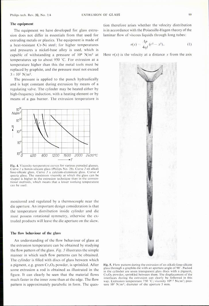
An understanding of the flow behaviour of glass atthe extrusion temperature can be obtained by studyingthe flow pattern of the glass. Fig. 5 illustrates the simplemanner in which such flow patterns can be obtained.The cylinder is filled with discs of glass between whicha pigment, e.g. green Cr203 powder, is sprinkled. Aftersome extrusion a rod is obtained as illustrated in thefigure. It can clearly be seen that the material flowsmuch faster in the inner zone than at the edge. The flowpattern is approximately parabolic in form. The ques-
tion therefore arises whether the velocity distributionis in accordance with the Poiseuille-Hagen theory ofthelaminar flow of viscous liq uids through long tubes:
LipvCx) = - (r2- x2).41}!
(1)
Here vex) is the velocity at a distance x from the axis
Fig. 5. Flow pattern during the extrusion of an alkali-lime-silicateglass through a graphite die with an aperture angle of90°. Packedin the cylinder are seven transparent glass discs with a pigment,Cr203 powder, sprinkled between them. The displacement of theinterfaces during the extrusion can clearly be followed in thisway. Extrusion temperature 750°C; viscosity 106.2 Ns/m>; pres-sure 107 N/m2; diameter of die aperture 5 mm.

lOO E.ROEDER Philips tech. Rev. 32, No. 3/4
of the tube (the die channel), LIp is the pressure differ-ence between the two ends of the tu be, 1 is the lengthand r the radius of the tube and 11the dynamic viscos-ity. At the wall (x = r) this law states that vex) is zero.
Whether the flow due to the extrusion of glass doesin fact obey this theory can be ascertained by plottingmeasured velocity values as a function of the pressuredifference LIp (fig. 6). A straight line is then obtainedin accordance with the well-known Poiseuille-Hagenequation for the volume flow V, given after integration 002of equation (I) by:
nLlpr4v=--8111
The theoretical curve (chai n-dotted li ne) agrees wellwith the experimental curve J, obtained using a diemade of a nickel-base alloy.
If however a die of graphite or boron nitride is used(curves 2 and 3) the curves, though still straight, arevery much steeper. This may be explained by assuming"slip" of the glass along the wallof these self-lubricat-ing materials, resulting in a higher velocity.
008cmls _J_o
V,L'u
!LVI
h.~2~(I
~ ~ .....x--V_ ~_:. - -1-=~~.
006
v
rooI,
(2)4 6
-L1pFig. 6. The extrusion rate v (the volume flow V divided by :n;r2)of an alkali lime-silicate glass plotted as a function of the pres-sure difference Lip between the ends of the die channel. Low ex-trusion rates were used to keep the experimental conditions con-stant. Extrusion temperature 680°C; viscosity 107.67 Ns/m2;diameter and length of the die channel 4 and JO mm. The chain-dotted line is the theoretical curve corresponding to the Poiseuille-Hagen theory. 1,2 and 3 are experimental curves obtained usingdies made of three different materials: a nickel-base alloy, boronnitride and graphite. The steeper slope of curves 2 and 3 is con-nected with the occurrence of slip along the wall.
2
Fig.7. Cross-section of extruded alkali lime-silicate glass, using a Cr-Ni steel die (on theleft) and a graphite die (on the right), compared with the cross-section of the die aperture.It can be seen that the extruded glass "swells" in the first case but not in the second case.Extrusion temperature 750°C; viscosity 107.4 Ns/rn"; pressure 107 N/m'; side of triangle10 mm.
The speed of the extrusion process may be as highas a few tens of centimetres per minute for glasses thatdo not crystallize easily (in which case a high tempera-ture can be chosen). For glasses that do crystallizeeasily, however, lower temperatures and thereforelower speeds have to be accepted.
Accuracyafshape
In the extrusion of glass through metal dies of cir-cular cross-section it is almost always found that thediameter of the product is about 10% greater than thatof the die aperture. This is not the case, however, inextrusion through a graphite die.
With round profiles these changes of diameter areeasy to correct by changing the die aperture. Non-cir-cular cross-sections, however, give rise to more com-plicated deviations, which are not so easy to correct.
For example, a triangular aperture in a die of Cr-Nisteel results in a rod with a cross-section as illustratedin fig. 7 (on the left), showing a "swelling" of the sidewalls. This swelling effect is not found with the samedie made of graphite (fig. 7, on the right).
This effect may possibly be attributable to the cool-ing of the emergi ng mass of glass, gi ving rise to a colder,more viscous outside layer which is consequently"blown up" [4] as a result of the central part of themass flowing at a higher speed. When a graphite dieis used, the difference in speed between the outside layerand the bulk of the material is so much less, owing toslip at the walls, that the effect is negligible.
[4J Visco-elastic effects mayalso be involved here ; see forexample A. C. Merrington. Nature 152, 663, 1943, andJ. Sertin in Encyclopedia of Physics VIlTjI, Springer, Berlin1959, in particular p. 242.

Philips tech. Rev. 32, No. 3/4 EXTRUSION OF GLASS 101
a
b
Fig. 8. Principle of two methods of extrusion cladding. In (a)two discs of different glass are used (light and dark grey). Thelower disc provides the cladding, the upper disc the core. In (b)the core material is introduced beforehand into a hollowmandrel.
Extrusion cladding
To conclude this article we shall briefly discuss aninteresting variant of the glass extrusion process, madepossible by the characteristic flow pattern in extrusion.This variant, which we have called extrusion cladding,is a method of extruding bars or tubes with a sleeve ofa different type ofglass. In its simplest form the methodconsists in extruding two discs of dissimilar glass placedone on top of the other (fig. 8a). There are two con-ditions to be met by this method ofextrusion cladding:the viscosities of the two types of glass must not differtoo widely, and the coefficient of expansion of thecladding glass must not be greater than that of the coreglass. If the cladding glass shrinks more than the coreglass during the cooling, then tensile stresses are createdand cracks appear in the surface.
It is easy to see that the thickness of the cladding isnot constant over the whole length of the prod uct ex-truded in this way. A product with a cladding of con-stant thickness can be obtained using the method illus-trated in fig. 8b. A rod of core glass is introduced be-forehand into a hollow mandrel. The cladding glass isthen applied around it and heated to its appropriateextrusion temperature. In this method the viscosity ofthe core glass must be much higher than that of thecladding glass. In a similar way a metal wire can becoated with glass. The relative coefficients of expansionmust then meet the same requirements as for glass onglass.
Summary. The extrusion technique has much to offer forthe shaping of "short" glasses, glasses that easily crystallize(devitrify) and high-melting glasses. Rods and tubes of widelydifferent profile can be produced with this technique. Extrusionrates can be of the order of a few tens of cm/min. A good pictureof the flow pattern during extrusion can be obtained by fillingthe extrusion cylinder with glass discs and applying a pigmentbetween them. If the extrusion die is made of Cr-Ni steel theflow behaviour follows the Poiseuille-Hagen theory. If it is madeof graphite, the glass exhibits "slip" along the walls. In the firstcase the extruded product "swells" upon emerging from the dieaperture, in the second case it does not. The article concludeswith a description of a variant of the technique, called extrusioncladding, which produces a glass rod or tube coated with glassof a different type. The method can also be used for coating ametal wire with glass.

102 Philips tech. Rev. 32, No. 3/4
under the objective in a stationary temperature field; the solid/liquid interface is then also stationary with respect to the objec-tive. By using eutectics with at least one birefringent phase,differences in crystal orientation can be made visible as differ-ences in colour by using polarizers.
The photograph (magnification 1200 x) shows a thin layer ofthis type after solidification. It consists of a eutectic in which onephase is birefringent and the other (the phase that is mainlybrown) is not. The unidirectional solidification started at thelower polycrystalline layer. It can be seen that with the upwardmovement of the solid/liquid interface from seed crystals in theoriginal structure various regions have grown, each of which hasits own typical lamellar orientation. During the solidificationprocess some regions are gradually ousted by others (competitivegrowth), so that finally only a few remain. Traces of growth ratefluctuations, splitting up the lamellae, can be seen just above thecentre of the photograph.
Growth of "composites" by unidirectional solidification
Composites are anisotropic materials in which two (or possiblymore) different phases are arranged in a periodic pattern, forexample in the form of lamellae or needles. They can be obtainedby unidirectional solidification of a melt of eutectic composition.This requires a flat solid/liquid interface moving at a constantrate (e.g. 10 cm/h). The segregating phases then arrange them-selves into a periodic structure (order of magnitude of the periodI micron). Certain relationships characteristic of the eutectic arefound between the growth direction, the crystallographic direc-tions of the phases and the geometry of the crystals. There isusually a small angle between the lamellae or needles and thegrowth direction.
In investigations of these solidification processes at PhilipsResearch Laboratories the solid/liquid interface where thecrystal-growth process takes place is directly observed with amicroscope. A thin layer (about 10 [J.m) of a molten eutecticmixture between fused-silica plates is moved at a suitable rate