ezradiopro-dk · pdf filethis user's guide describes the development kits of the...
TRANSCRIPT

Rev. 0.5 9/14 Copyright © 2014 by Silicon Laboratories EZRadioPRO-DK
EZRadioPRO-DK
EZRADIOPRO® DEVELOPMENT KITS USER’S GUIDE
1. Kits Overview
This user's guide describes the development kits of the EZRadioPRO wireless development kit family. Each kitcontains two RF nodes based on the Wireless Motherboard to support evaluation and development of sub-GHz RFlinks with the different EZRadioPRO devices. Table 1 lists the RF pico boards of the kits that use the latest C2Arevision of the EZRadioPRO ICs. Table 2 lists the RF pico boards of the obsolete kits that use the previous B1Brevision of the EZRadioPRO ICs. Table 3 lists the content that is common to all kits.
Table 1. RF Pico Boards of the EZRadioPRO Development Kits
Qty Description Part Number
Si4461 Development Kit 868 MHz 4461C-868-PDK
2 Si4461 RF Transceiver Pico board 868 MHz, 14 dBm, direct tie 4461CPCE14D868-EK
Si4438 Development Kit 490 MHz 4438C-490-PDK
2 Si4438 RF Transceiver Pico board 490 MHz, 20 dBm, direct tie 4438CPCE20D490-EK
Si4463 Development Kit 915 MHz 4463C-915-PDK
2 Si4463 RF Transceiver Pico board 915 MHz, 20 dBm, switched 4463CPCE20C915-EK
Table 2. RF Pico Boards of the obsolete EZRadioPRO Development Kits
Qty Description Part Number
Si4060/Si4362 Development Kit 868 MHz 4060-868-PDK
1 Si4060 RF Transmitter Pico Board 868 MHz, 10 dBm 4060-PCE10B868-EK
1 Si4362 RF Receiver Pico Board 868 MHz 4362-PRXB868-EK
Si4063/Si4362 Development Kit 915 MHz 4063-915-PDK
1 Si4063 RF Transmitter Pico board 915 MHz, 20 dBm 4063-PCE20B915-EK
1 Si4362 RF Receiver Pico board 915 MHz 4362-PRXB915-EK
Si4461 Development Kit 868 MHz 4461-868-PDK
2 Si4461 RF Transceiver Pico board 868 MHz, 14 dBm, direct tie 4461-PCE14D868-EK
Si4438 Development Kit 490 MHz 4438-490-PDK
2 Si4438 RF Transceiver Pico board 490 MHz, 20 dBm, direct tie 4438-PCE20D490
Si4463 Development Kit 915 MHz 4463-915-PDK
2 Si4463 RF Transceiver Pico Board 915 MHz, 20 dBm, switched 4463-PCE20C915-EK
Table 3. Content Common to Every Kit
Qty Description Part Number
2 Wireless Motherboard MSC-WMB93X
2 C8051F930 MCU Pico Board UPPI-930-RF
2 USB cable (USBA-USB mini)
2 Antenna with SMA connection MSC-AT50-XXX
1 Kit user guide

EZRadioPRO-DK
2 Rev. 0.5
2. Software Setup
There are two software tools provided by Silicon Labs to aid in EZRadioPRO software development, the WirelessDevelopment Suite (WDS) and the Silicon Labs Integrated Development Environment (IDE). The recommendedstarting point for EZRadioPRO development is the WDS software tool. This tool is able to identify the connectedboards by reading their identification memories (EBID) and provides valuable help by greatly simplifying radioconfiguration, evaluation, and application development.
2.1. Hardware and Software Requirements for WDSThe following hardware and software is required to run the WDS:
Windows XP or later
Microsoft .NET framework 3.5 or later
Silicon Labs CP210x VCP driver
WDS v3.2.7.0 or later
The lack of the .NET framework and VCP driver are recognized during the WDS installation. The install wizard willinstall the missing components after prompting the user for consent.
2.2. Download WDSWDS can be obtained from the Silicon Labs web site free of charge at
http://www.silabs.com/Support%20Documents/Software/WDS3-Setup.exe
2.3. Installation StepsIf WDS is already installed on your machine, skip this section.
Note: Before installing this software, local administration rights must be obtained from your network administrator.
1. Start WDS3-Setup.exe.
2. Click “Next” to start the installation process.
3. Accept the license agreement by clicking the check box, and then press the “Next” button.
4. Select the installation folder.It is recommended to use the default folder, C:\Program Files\Silabs\WDS3
5. When your settings are confirmed, click “Install” to continue.
6. Click “Finish” to close the WDS Installer.

EZRadioPRO-DK
Rev. 0.5 3
3. Hardware Setup
After checking the kit contents against Tables 2 and 3, the kit can be put into operation by performing the stepslisted below.
Figure 1. Wireless Motherboard Top Markings
1. Insert an RF Pico board into the connectors labeled as CON1 and CON2 on the Wireless Motherboard (WMB).
2. Insert a UPPI-930-RF MCU Pico Board into the connectors, J5, J6, J7, and J8, on the WMB. The dotted corner of the F930 MCU has to point to the triangle symbol on the WMB.
3. Connect the antenna to the SMA connector on the RF Pico Board.
4. Set the SUPPLY SELECT switch to the USB position.
5. Set the MCU DC/DC switch to the OFF position.
6. Ensure that all the CURRENT MEASUREMENT jumpers are in place.
7. Start the WDS on your PC.
8. Using one of the USB cables in the kit, connect the WMB to the PC.
9. If necessary wait for Windows to install the debug interface driver.
10. WDS must identify the connected board and open an Application Manager window that lists information about the identified board.
11. Boards are shipped without preloaded software. Sample codes can be configured and downloaded to the MCU from WDS. For details on how to use the WDS, see the WDS User's Guides listed in "4. Useful Documentation" on page 5".

EZRadioPRO-DK
4 Rev. 0.5
Figure 2. WDS Application Manager Window
Repeat steps 1 to 9 for the other node of the kit.
The two nodes are now ready for evaluation. Detailed descriptions of the example codes can be found in theprogramming guide listed in "4. Useful Documentation" on page 5.
The following is a quick-step guide to performing simple packet TX/RX.
1. Leave both nodes powered from the USB as described above.
2. Select “Radio Configuration Application”.
3. From the Radio Configuration Application window, select “Standard Packet TX” for one node and “Standard Packet RX” for the other node.
4. 4Leave the default parameter settings untouched; simply click “Download project”.
5. Now, the simple TX/RX sample project is running on the boards. When pressing one of the SW1 to SW4 buttons on the TX board, packets are sent, and the corresponding LED of LED1 to LED4 lights up during the transmission. On the RX side, LED1 is always on, while different combinations of LED2 to LED4 light up during successful packet reception according to the button pressed.

EZRadioPRO-DK
Rev. 0.5 5
4. Useful Documentation
For general information on the EZRadioPRO chips, see the following data sheets:
Si406x Data Sheet
Si4362 Data Sheet
Si446x Data Sheet
For hardware design guidance, see the following application notes:
AN627: Si4060/Si4460/61 Low-Power PA Matching
AN629: Si4460/61/63/64 RF ICs Layout Design Guide
AN643: Si446x/Si4362 RX LNA Matching
AN648: Si4063/Si4463/64 TX Matching
For detailed information on lab measurements and data sheet parameter verification, refer to the followingapplication notes:
AN655: Range Test Application for EZRadio® and EZRadioPRO®
AN796: Wireless Development Suite General Description
AN632: WDS User's Guide for EZRadioPRO® Devices
For detailed information on programming the radio, refer to the following documents:
Si406x API Descriptions
Si4362 API Descriptions
Si446x API Descriptions
AN633: Programming Guide for EZRadioPRO® Si4x6x Devices
Download WDS3 installer
Download Silicon Laboratories IDE installer
More useful documents can be accessed via the EZRadioPRO web pages athttp://www.silabs.com/products/wireless/EZRadioPRO/Pages/default.aspx

EZRadioPRO-DK
6 Rev. 0.5
5. The Wireless Motherboard Hardware Platform
The wireless motherboard platform is a demo, evaluation, and development platform for EZRadioPRO radio ICs. Itconsists of a wireless motherboard and interchangeable MCU and RF pico boards.
Figure 3. 8-bit Wireless Motherboard Platform

EZRadioPRO-DK
Rev. 0.5 7
5.1. The Wireless Motherboard
Figure 4. Wireless Motherboard
The wireless motherboard contains four pushbuttons, four LEDs, and a buzzer as simple user interfaces. Agraphical LCD displays menu items for range testing purposes and a potentiometer demonstrates analogcapabilities of the MCU. A switch supports the power options of the MCU's built-in dc/dc converter. Using thecurrent measurement jumpers, current consumption can be measured separately either for the MCU, the radio, orthe peripherals. The motherboard contains test pins for all I/O pins of the MCU and for all digital pins of the radio. Inaddition, there are SMA connectors for the GPIOs of the radio for test equipment connection. A USBcommunication interface as well as a built-in Silicon Labs USB-to-C2 debug adapter are integrated onto the boardso that the wireless motherboard (WMB) can be directly connected via USB to the PC for downloading anddebugging code on the MCU.
An interface connection towards sensor modules can also be found. The MCU is also connected to the RF picoboard through a connector pair.
MCU Pico Board RF Pico Board
Current Measurement Pins
Radio Test Pins
Radio GPIO Connectors
BuzzerReset ButtonPush ButtonsPotentiometer
MCU DC/DC Converter
Switch
MCU Test Pins
Power Supply Switch
Sensor Module
Connector
External Power Supply
Connection
USB Communication
and Debug Interface

EZRadioPRO-DK
8 Rev. 0.5
5.2. Power SchemeThe power source of the platform can be selected with the power supply selector switch “SUPPLY SELECT” on theWMB board. If this switch is in the ”USB” position, supply voltage is provided by the PC that is connected to the”J16” mini USB connector. If this switch is in the ”BAT” position, the supply voltage is provided by two AA batteriesin the battery holder on the bottom side of the board. If the ”SUPPLY SELECT” switch is in the ”EXT” position,supply voltage is provided by an external power source through the ”TP7” and “TP9” points.
Using the ”MCU dc/dc” switch, the internal dc/dc converter of the C88051F930 MCU on the MCU pico board canbe activated if the connected pico board supports this function. If the switch is in ”OFF” position, the MCU's dc/dcconverter is inactive and the supply voltage is only determined by the state of the “SUPPLY SELECT” switch.
Positioning the switch to either ”LDO (1.25 V)” or ”1 CELL” position will turn on the MCU's dc/dc converter byconnecting 1.25–1.5 V supply voltage to the VBAT pin and removing external power from the VDC pin. The MCUwill provide 1.9 V in default setting on its VDC pin to all the other connected loads. Since this current is limited, itmay be necessary to disconnect or disable some loading part of the board. For further details, see the MCU datasheet and the board schematic. The board schematic can be found in the EZRadioPRO Development Kit User'sGuide. A complete CAD design pack of the board is also available at www.silabs.com.
5.3. RF Pico Board
Figure 5. RF Pico Board Front Side
The RF pico board is a radio module that contains an EZRadioPRO radio IC, matching network and an SMAconnector on the top side. These components apart from the antenna connector are covered by a metal shield fornoise reduction. The digital signals of the radio (SCLK, SDI, SDO, NSEL, SCL, SDA, VDD and GND) can beaccessed on test points at the edge of the board. The boards also have a factory loaded board identificationmemory (EBID) on the bottom side that contains data that describes the board properties. Via the unified RF picoconnector pair on the bottom side of the board, any RF pico board can be connected to the WMB.

EZRadioPRO-DK
Rev. 0.5 9
The schematic of an RF Pico Board can be found in the next chapter. The complete CAD design pack of each RFpico board type is also available at www.silabs.com.
5.4. Setting up and Connecting the WMB to the PCSteps for connecting the platform to the PC:
1. Connect an RF Pico Board to the WMB board through the CON1 and CON2 connectors.
2. Insert a UPPI-930-RF MCU pico board in the connectors J5, J6, J7, J8 on the WMB. The dotted corner of the C8051F930 MCU has to point to the triangle symbol on the WMB.
3. Connect an antenna to the SMA connector on the RF Pico Board.
4. Select the desired power source with the SUPPLY SELECT switch.
5. Ensure that all the CURRENT MEASUREMENT jumpers are in place.
6. Connect the WMB board to a USB port of the PC.
7. Wait for Windows to install the driver of the debug interface if necessary.
Table 4. Connections between the WMB Board and the RF Pico Board
Si446x, Si4362, Si406x, Si4438 WMB C8051F930
Pin Number Pin Name Pin Function RF Pico board J1 connector
WMB Con2 connector
Pin Name
EP,18 GND Ground 2 1,2,19,20 GND
8 VDD Voltage Supply input 1 17,18 VDD
11 NIRQ Interrupt outputactive low
10 7 P0.1
1 SDN Shutdown inputactive high
3 8 P2.3
15 NSEL SPI select input 6 6 P1.4
12 SCLK SPI clock input 9 5 P1.0
14 SDI SPI data input 7 3 P1.2
13 SDO SPI data output 8 4 P1.1
9 GPIO_0 General Purpose I/O 12 11 P2.6 (2nd)
10 GPIO_1 General Purpose I/O 11 12 P1.3
19 GPIO_2 General Purpose I/O 5 13 P2.5
20 GPIO_3 General Purpose I/O 4 14 P2.4

EZRadioPRO-DK
10 Rev. 0.5
6. Wireless Motherboard Schematics
Fig
ure
6.W
irel
ess
Mo
ther
bo
ard
Sch
emat
ic (
1 o
f 4)

EZRadioPRO-DK
Rev. 0.5 11
Fig
ure
7.W
irel
ess
Mo
ther
bo
ard
Sch
emat
ic (
2 o
f 4)

EZRadioPRO-DK
12 Rev. 0.5
Fig
ure
8.W
irel
ess
Mo
ther
bo
ard
Sch
emat
ic (
3 o
f 4)

EZRadioPRO-DK
Rev. 0.5 13
Fig
ure
9.W
irel
ess
Mo
ther
bo
ard
Sch
emat
ic (
4 o
f 4)

EZRadioPRO-DK
14 Rev. 0.5
RF S
ection
RF E
BID
50O
hm lo
ad
Si44
63 C
lass
-E +
20 d
Bm m
atch
ing
for
915
MHz
C1 2.2u
F
C2 100n
F
C3 100p
F
C4 33pF
C5 100n
F
Q1
30M
Hz
R7 4R7
1A0
2A1
3A2
4VS
S5
SDA
6SC
L7
WP
8VC
CU3
24AA
64T-
I/M
NY
C11
100n
F
1 2 3 4 5 6 7 8 9 10 11 12 13 14 15
J1
CM2
4.3p
F
CM1
2.7p
F
CR2
1.0p
F
CR1
3.0p
F
C0
3.3p
F
LM1
10nH
LR1
18nH
CC2
56pF
LM3
8.2n
H
LM2
10nH
LR2
22nH
L0 13nH
1O
UT1
2GND
3O
UT2
4VC
25
RF_I
N6
VC1
U2
uPG22
14TB
CC1
56pF
SJ9
SJ10
LC3
120nH
C9
56pF
CM3
4.3p
F
SJ1
1TX
RAM
P
RF S
hiel
d
U4
SHIE
LD_B
MI-
S-20
3-F
TRX
CC3
56pF
1SD
N2
RXP
3RX
N4
TX5
NC
6VBATA 7TXRAMP 8VBATD 9GPIO_0 10GPIO_1
11NIR
Q12
SCLK
13SD
O14
SDI
15NSE
L
16 XOUT17 XIN18 GNDX19 GPIO_220 GPIO_3
EPEP
U1
SI44
63
CM 4.7p
F
12
34
56
78
910
1112
1314
1516
1718
1920
RFP1
SFH31
-NPP
B-D10
-SP_
ASSY
MET
RIC
12
34
56
78
910
1112
1314
1516
1718
1920
RFP2
SFH31
-NPP
B-D10
-SP_
ASSY
MET
RIC
PCB
stic
ker
1S1
PCB_
STIC
KER_
13X2
5MM
RF_SDN
RF_GPIO_3RF_GPIO_2
RF_M
OSI
RF_M
ISO
RF_S
CLK
RF_N
IRQ
RF_G
PIO
_0
RFVD
D
RF_M
OSI
RF_M
ISO
RF_S
CLK
RF_N
SEL
RF_N
IRQ
RF_S
DN
RF_G
PIO
_0RF
_GPI
O_1
RF_G
PIO
_2RF
_GPI
O_3
RFVD
DRF
VDD
EBID
_SCL
EBID
_SDA
VPP
VPP
VPP
VPP
VPP
RF_S
DN
RF_G
PIO
_3RF
_GPI
O_2
RF_N
SEL
RF_M
OSI
RF_M
ISO
RF_S
CLK
RF_N
IRQ
RF_G
PIO
_1RF
_GPI
O_0
EBID
_SCL
EBID
_SDA
RF_G
PIO
_1
RF_N
SEL
RFVD
D_T
X
RF_G
PIO
_2
RF_G
PIO
_0
RXN
RXP
TX1
RFVD
DRF
VDD
RFVD
D_T
X
Fig
ure
10.R
F P
ico
Bo
ard
EZRadioPRO-DK
Rev. 0.5 15
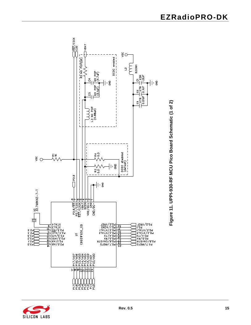
Fig
ure
11.U
PP
I-93
0-R
F M
CU
Pic
o B
oar
d S
chem
atic
(1
of
2)

EZRadioPRO-DK
16 Rev. 0.5
Fig
ure
12.U
PP
I-93
0-R
F M
CU
Pic
o B
oar
d S
chem
atic
(2
of
2)

DisclaimerSilicon Laboratories intends to provide customers with the latest, accurate, and in-depth documentation of all peripherals and modules available for system and software implementers using or intending to use the Silicon Laboratories products. Characterization data, available modules and peripherals, memory sizes and memory addresses refer to each specific device, and "Typical" parameters provided can and do vary in different applications. Application examples described herein are for illustrative purposes only. Silicon Laboratories reserves the right to make changes without further notice and limitation to product information, specifications, and descriptions herein, and does not give warranties as to the accuracy or completeness of the included information. Silicon Laboratories shall have no liability for the consequences of use of the information supplied herein. This document does not imply or express copyright licenses granted hereunder to design or fabricate any integrated circuits. The products must not be used within any Life Support System without the specific written consent of Silicon Laboratories. A "Life Support System" is any product or system intended to support or sustain life and/or health, which, if it fails, can be reasonably expected to result in significant personal injury or death. Silicon Laboratories products are generally not intended for military applications. Silicon Laboratories products shall under no circumstances be used in weapons of mass destruction including (but not limited to) nuclear, biological or chemical weapons, or missiles capable of delivering such weapons.
Trademark InformationSilicon Laboratories Inc., Silicon Laboratories, Silicon Labs, SiLabs and the Silicon Labs logo, CMEMS®, EFM, EFM32, EFR, Energy Micro, Energy Micro logo and combinations thereof, "the world’s most energy friendly microcontrollers", Ember®, EZLink®, EZMac®, EZRadio®, EZRadioPRO®, DSPLL®, ISOmodem ®, Precision32®, ProSLIC®, SiPHY®, USBXpress® and others are trademarks or registered trademarks of Silicon Laboratories Inc. ARM, CORTEX, Cortex-M3 and THUMB are trademarks or registered trademarks of ARM Holdings. Keil is a registered trademark of ARM Limited. All other products or brand names mentioned herein are trademarks of their respective holders.
http://www.silabs.com
Silicon Laboratories Inc.400 West Cesar ChavezAustin, TX 78701USA
Simplicity StudioOne-click access to MCU tools, documentation, software, source code libraries & more. Available for Windows, Mac and Linux!
www.silabs.com/simplicity
MCU Portfoliowww.silabs.com/mcu
SW/HWwww.silabs.com/simplicity
Qualitywww.silabs.com/quality
Support and Communitycommunity.silabs.com