f-14 tomcat park jet -...
TRANSCRIPT

Page
© 2005 3D Foamy All Rights Reserved
1
F-14 Tomcat Park Jet Made In Washington State, USA!
Kit# 3DF0F14
A High Performance Electric Jet
About This Construction Manual This booklet divides the construction into sub-assemblies; wing, fuselage, etc. Please read each section carefully before starting on that particular sub-assembly. There is a complete description of all parts under “Kit Contents” Please check to make sure your kit is complete. We are human, and occasionally miss something! If you have trouble identifying a part, or are missing something, please contact us and we can help. During the construction process the steps will outline what part to use. We have used actual pictures instead of unclear or often inaccurate illustrations to assist in the building process. This manual is intended for English users, and all measurements are made in standard units (inch, foot, etc.)
Customer Service: Should you experience a problem building or flying this kit, we recommend you see your hobby shop first. If you are unable to solve the problem, feel free to contact: Further updates can be found on our website
[email protected] or online at www.3DFoamy.com
This product is sold with exclusion of all warrantee, expressed or implied, statutory or otherwise.
Pilot assumes all risk in building and operating this model. Do not operate if you are not an experienced modeler. Refer to and abide by AMA rules at www.modelaviation.com for regulations on Radio Control Models.

Page
© 2005 3D Foamy All Rights Reserved
2
Kit Contents Part No. QTY. Dimensions Description
007201a 1 Laser Cut Foam Foam Kit Parts A 6mm 007201b 1 Laser Cut Foam Foam Kit Parts B 6mm 007201c 1 Laser Cut Foam Foam Kit Parts C 6mm 007201d 1 Laser Cut Foam Foam Kit Parts D 3mm
007207 2 ¼ Nylon Bolts Wing swing bolts 007206 1 (1)2-56 rod and (4)ends Swing wing pushrods 007205 2 EZ links and pushrods Stabilator control parts 007204 1 Laser cut 1/8” ply Plywood parts 007202 2 .21” dia carbon tube Wing Spar 007203 2 .21” carbon tube Stabilator spar/pivot 007209 1 Laser Cut Plastic Control Horns/Doublers 007210 1 Intro Sheet Getting Started Paper

Page
© 2005 3D Foamy All Rights Reserved
3
Additional items you will need
□ 5 Ch radio system with 3-4 micro servos (HS-55 or similar) and micro receiver (Hitec Electron 6)
□ Motor (Himax 2015-4100 gearbox recommended)
□ Props (APC 9x6 recommended)
□ Odorless Medium CA and accelerator. (Accelerator a must)
□ Connectors – Dean’s Ultra connectors are recommend for this model.
□ Speed Control (Castle Creations Phoenix 25 recommended)
□ 5 or 15 minute Epoxy □ Li-Poly Battery pack (1200-1500 mah 3s1p recommended)**
□ Li-Po Charger (Must be approved for Li-Po Cells!)
□ 3M Satin tape □ Extra high quality flexible hook up wire (16 gauge minimum)
□ Foam-safe contact glue (sold at most craft stores)
Building supplies that make it easy
□ Scissors □ Sand paper (150, 220, and 320 grit) □ Steel straight edge □ Razor saw □ Hobby Knife and extra blades □ Small building square □ Rubbing Alcohol □ Pencil and Pen □ Wire cutters □ Soldering iron □ Assorted screwdrivers □ Paper towels
Definitions• LE- Leading Edge • CA- “Super Glue” • Brushless- New
motors, no brushes, computer controlled.
• 3S1P- 3 cells, 1 Pack • 3S2P- 3 cells, 2 packs
• ESC—Electronic Speed Control
• TE- Trailing Edge • Brushed- Normal motor type, brushes, can, magnets.
• Li-Poly-New Battery packs. Lithium Polymer (Cell phone battery)
• “C” Rating- the maximum charge or discharge rate of the cell. A 1000 mah pack rated at “10C” could provide a 10 amp discharge. All packs should be charged at “1C”(1000mah pack should charge at 1000 mah max. That means a 1 hour charge time.

Page
© 2005 3D Foamy All Rights Reserved
4
tems
will
General Construction Notes 1) Start by thoroughly reading this manual, and also look carefully at the plans. Many i
are addressed more clearly on the plans. 2) Normal CA will melt the foam, but odorless CA can be used. Accelerator is a must! It
take hours to dry on its own… 3) PAINTING: Painting is not necessary. However, test the paint on a small scrap first. If
masking for painting, use blue low adhesive tape or else when the tape is removed, the film will inadvertently be removed as well. When removing the tape, pull the tape towards any edge of the film so that the film is not pulled loose. You will likely need to put striping tape between the colors as they can bleed under the tape. An alternative to painting is colored packing tape. It is easy to use, self adhesive, and low cost.
Electronics Notes There are many choices to make when deciding on your power system and it can get confusing. For good performance, it’s important that the motor/gearing/prop used for this model generate at least 18-20 oz static thrust and a 45-50 mph pitch speed. A program like MotoCalc (www.motocalc.com) is invaluable for analyzing potential power systems and is highly recommended. The recommended power setups for this model are summarized below. Both of these setups utilize efficient high-power brushless motors, and will provide excellent jet-like performance. Note that brushed motors (such as the GWS EPS-350) will not provide good performance on this model and are not recommended. Standard Brushless Setup Motor: Himax 2015-4100 with "B gearing (4.4:1) or Himax 2015-5300 with “C” gearing (5.3:1) Battery: High performance 1200-1500 mAh 11.1V lithium-polymer pack capable of supplying at least 12 amps continuous. Note that 7.4V lithium-polymer battery packs will not provide adequate performance on this model and should not be used. Speed Control: Castle Creations Phoenix 25 brushless controller Prop: APC 9x6 or 9x7.5 slow flyer This setup will produce 21 oz static thrust with 50 mph top speed and will provide exhilarating performance with nearly 1:1 thrust-to-weight ratio (if you build light).

Page
© 2005 3D Foamy All Rights Reserved
5 Brushless Outrunner Setup Motor: Axi 2212/26, Hacker A20-20L, 22L Battery: High performance 1200-1500 mAh 11.1V lithium-polymer pack capable of supplying at least 12 amps continuous. Note that 7.4V lithium-polymer battery packs will not provide adequate performance on this model and should not be used. Speed Control: Castle Creations Phoenix 25 brushless controller Prop: APC 9x6 or 9x7.5 slow flyer This setup will produce 19 oz static thrust with 50 mph top speed. It doesn’t have quite as much power as the recommended Himax motors above, but the Axi outrunner is extremely smooth and quiet in operation and has none of the gearbox noise of the Himax. This motor is a pleasure to fly. Note that you’ll need a GWS stick mount adapter to mount the Axi and Hacker to the hardwood motor mount on this model. Please note this model was designed to be a lightweight parkflyer and was not designed to handle extremely powerful motor systems and high flying weights. Thus, avoid the temptation to overpower this model unless you have the knowledge and experience to modify the design appropriately!

Page
© 2005 3D Foamy All Rights Reserved
6 About your Plane Your aircraft was designed by computer (CAD) for accuracy and construction ease. All parts have been precision cut on a CNC laser cutting system right here in the 3D Foamy shop! The foam used in your kit is the best quality available. Depron is very light and stiff and is also very forgiving and easy to paint. However, because we want weight at the minimums, the planes are still somewhat fragile, so a little care can go a long way. Note that this model is intended for experienced modelers, and is not suitable for beginners. If you’re comfortable flying a fast sport aerobatic airplane, you can probably handle this model. I hope that you are going to enjoy building and flying this plane as much as I have! Best of luck, and don’t hesitate to e-mail me with any questions or comments at [email protected]. P.S. If you think I can improve or clarify something in this manual, please let me know! Construction
Before Beginning All parts have been accurately cut on a computer-controlled laser cutting machine. Remove the aircraft parts from the foam packing sheets. Cut the tabs loose with a razor blade for best results. This model can be built using the following types of adhesives:
• Epoxy • Odorless cyanoacrylate (CA) with accelerator • UHU Creativ for Styrofoam (or UHU POR) (pictured at left) • 3M 77 spray adhesive • Hot glue gun • ProBond (or Gorilla Glue)
To minimize weight, try to use as little epoxy as possible on this model, saving it for only critical joints such as wing spars and motor mounts. For best results, the majority of construction should use a lightweight and quick-drying adhesive such as CA, UHU Creativ, and 3M 77.

Page
© 2005 3D Foamy All Rights Reserved
7
1. Begin assembly with the forward fuselage. Lay the two fuselage sides down flat on the work bench and glue the foam doublers to the locations shown on the plans. Be sure to make two mirror image parts—a left side and a right side. After the glue has dried, glue the three fuselage bulkheads to one of the fuselage sides at the locations shown, making sure they are perpendicular.
2. Next glue the two fuselage sides together. Set the fuselage sides upright and flat on the workbench, apply glue to the edge of the bulkheads, and push the sides together. After the glue has dried, glue this assembly to the fuselage bottom piece as shown. Glue the two forward fuselage top pieces in forward of the canopy (not shown in this photo).

Page
© 2005 3D Foamy All Rights Reserved
8
3. Laminate the nose cone pieces together using 3M 77 spray adhesive. Then glue the assembled nosecone block to the forward fuselage as shown (5 minute epoxy recommended). Once the glue has dried, carve the nose cone to shape. Start by tracing the top view on the top of the block and cutting the block to that outline. Begin with coarse sandpaper (60 grit) to rough out the basic shape, then move to progressively finer sandpaper (first 150, then 220 grit) to do the final shaping. Make the canopy using the same procedure. Note the canopy has two smaller sill pieces that glue on to each side of the canopy to form the lower sill.

Page
© 2005 3D Foamy All Rights Reserved
9
4. Begin assembly of the inlets. Be sure to make two mirror-image inlets! First glue the small plastic stabilizer support discs to each side around the laser cut circles for the stabilators, Then glue all the foam support strips as shown to both the inboard and outboard inlet sides. Glue the taileron servo doubler to the inboard inlet side. Use a heat gun to gently form the required curves in these pieces. Hold each piece next to the inlet bottom piece to judge the curvature required.
Page
© 2005 3D Foamy All Rights Reserved
10
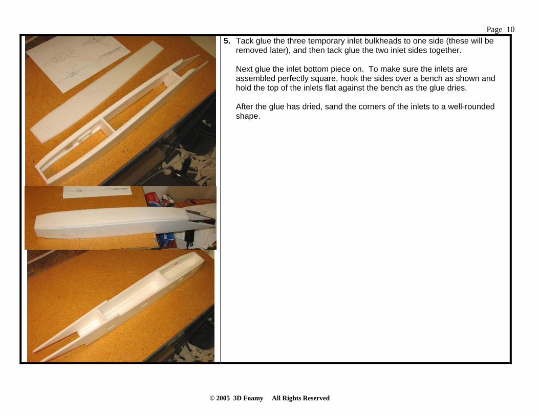
5. Tack glue the three temporary inlet bulkheads to one side (these will be removed later), and then tack glue the two inlet sides together. Next glue the inlet bottom piece on. To make sure the inlets are assembled perfectly square, hook the sides over a bench as shown and hold the top of the inlets flat against the bench as the glue dries. After the glue has dried, sand the corners of the inlets to a well-rounded shape.

Page
© 2005 3D Foamy All Rights Reserved
11 6. Glue the inlet diverters to the fuselage sides. Note the bottom of the
diverter butts up against the step in the fuselage bottom piece.
7. Laminate the five motor mount pieces together using 3M 77. Note the tabbed piece goes in the middle. Then sand the assembly to a tapered shape as shown. Laminate the motor mount with the 3 pieces from the ply sheet, glue in the motor mount using 5 minute epoxy.
Page
© 2005 3D Foamy All Rights Reserved
12
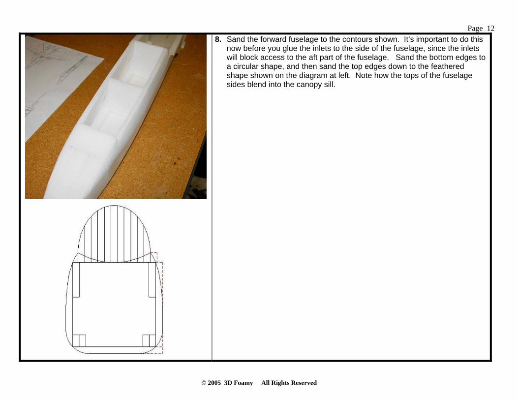
8. Sand the forward fuselage to the contours shown. It’s important to do this now before you glue the inlets to the side of the fuselage, since the inlets will block access to the aft part of the fuselage. Sand the bottom edges to a circular shape, and then sand the top edges down to the feathered shape shown on the diagram at left. Note how the tops of the fuselage sides blend into the canopy sill.
Page
© 2005 3D Foamy All Rights Reserved
13
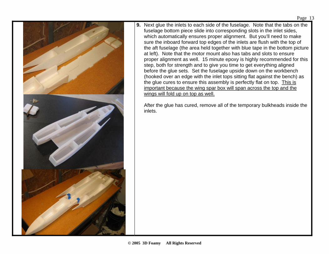
9. Next glue the inlets to each side of the fuselage. Note that the tabs on the fuselage bottom piece slide into corresponding slots in the inlet sides, which automatically ensures proper alignment. But you’ll need to make sure the inboard forward top edges of the inlets are flush with the top of the aft fuselage (the area held together with blue tape in the bottom picture at left). Note that the motor mount also has tabs and slots to ensure proper alignment as well. 15 minute epoxy is highly recommended for this step, both for strength and to give you time to get everything aligned before the glue sets. Set the fuselage upside down on the workbench (hooked over an edge with the inlet tops sitting flat against the bench) as the glue cures to ensure this assembly is perfectly flat on top. This is important because the wing spar box will span across the top and the wings will fold up on top as well. After the glue has cured, remove all of the temporary bulkheads inside the inlets.

Page
© 2005 3D Foamy All Rights Reserved
14 10. Next we’ll build the wing sweep mechanism. Begin by removing all the
laser-cut parts. Touch-up sand the pieces where necessary.
11. Glue the doublers to both ends of the spar box top and bottom pieces. Laminate the two spacer pieces and glue them in place on top of the doublers on one side. Then glue the balsa shear webs in place on the same side. Medium viscosity CA is recommended for all of these joints. Next laminate the two swing arm pieces together with CA. Be sure to make two mirror-image parts—the piece with the control arm goes on bottom for each side.
NOTE: Picture shows prototype with servo mount attached, this has been changed since and it is no longer one piece.

Page
© 2005 3D Foamy All Rights Reserved
15 12. Test fit the top and bottom spar box pieces together. Sand the balsa shear
webs as required until you get a perfect fit. Then glue the top and bottom pieces together with CA. Now drill the four holes for the nylon bolt wing pins to size—one in each end of the spar box and one in each swing arm. Use a drill press if at all possible to ensure the holes are perfectly perpendicular! I left them a tad undersized so you can drill to fit perfectly, I left the top holes a bit undersized and threaded the bolts into them so they stay in place. Test fit the swing arms and nylon bolts in place, and check to see if they rotate smoothly. You want them to fit tightly but still rotate smoothly. Sand the swing arms as required to thin them down until they turn smoothly. Note that you can also adjust the tension of the swing arms by tightening the nylon nut and bolt, so it’s OK if the swing arms end up a little loose.

Page
© 2005 3D Foamy All Rights Reserved
16 13. Cut the carbon tube wing spars to length and test fit the swing arms and
spars into the wing, trimming as required. Then glue the swing arms and spars in place using epoxy (note that the side with the control arm goes down on the swing arms). Place wax paper and heavy books on top of the wings as the epoxy cures to ensure everything stays perfectly flat. After the glue cures, put a strip of 3M Satin tape over the top and bottom of the spar to help hide the joint and provide a smooth wing surface. Now sand the wing to shape. Sand the leading edge to a well-rounded shape and sand the trailing edge down to a tapered shape from the top. This will result in a thin flat-bottom airfoil. Put a strip of Satin tape over the leading edge to provide durability and smoothness.
14. Glue the 3 1/8” thick spacer blocks in the bottom center of the wing swing box. However, check the fit of your servo first to see if this thickness puts the servo arm at the same height as the control arms on the wing swing arms. You may need to use a thicker or thinner spacer depending on your servo. 3/8” is what worked for the HS-81MG servo used in the prototype.

Page
© 2005 3D Foamy All Rights Reserved
17 15. Attach the 1/8” lite-ply servo arm extension to the nylon servo arm with two
screws as shown. You may need to experiment to find the exact hole locations that result in both wings swinging identically forward to back—and those locations may not be symmetrical. I found that the left wing needs a little longer moment arm than the right wing to swing equally. If one wing swings more than the other, simply increase the moment arm on that side. The already laser cut positions are what worked (after much experimenting) with the HS-81MG servo used in the prototype. Also note that if this horn seems weak to you (only .25” wide), that’s by design! This servo arm is intended to be the weak link in the wing swing mechanism. That way, if you catch a wing on landing, this horn will break before anything else in the system breaks. This is good because this horn is easy and quick to replace via the hatch in the top of the fuselage. This design has already paid off for me—I had a crash landing in one of the early flights and this arm broke just as intended, preventing any further damage to the wing or swing mechanism!
16. Glue 1/8” lite-ply strengthener to the bottom of the servo tray as shown. Then check the fit of the servo and trim as required. When done, the assembly should look like the picture on bottom. A Hitec HS-81MG servo was used on the prototype, which works OK but is definitely straining in this application. An HS-85MG servo is a little heavier but provides more torque and will work better for most and is recommended. But whatever servo you choose, make sure to use a METAL geared servo since a nylon geared servo is very likely to strip.

Page
© 2005 3D Foamy All Rights Reserved
18 17. Glue the servo tray on the bottom of the spacer.
Make and install the wing swing pushrods using 2-56”” threaded rods with steel clevises on each side. Silver solder the inside clevices onto the rod.
18. Now plug the servo into your receiver and test the wing swing mechanism, adjusting it as required until it works perfectly. You want both wings to swing easily and also swing the same amount. If one wing swings more than the other, adjust the control throws on the servo control arm. If the wings tend to bind, sand the swing arms down in thickness. Use the buzzing of the servo to tell you where the problems are—it’ll buzz heavily if it encounters something it doesn’t like! For reference, there are mechanical stops on both ends of the wing swing travel. The step in the wing trailing edges should just touch the back of the wing swing spar box when the wings are swept fully aft. And the control arms on the wing swing arms should hit the forward side of the spacer inside the spar box when the wings are fully forward. Use those extremes to gauge how much swing is required. Note that a key feature of this design is that it is independent from the rest of the airframe. Thus, everything can be tested and adjusted to work perfectly BEFORE you install it.

Page
© 2005 3D Foamy All Rights Reserved
19 19. Test fit the wing swing box onto the fuselage. The forward side of the spar
box butts up against the step in the inlet tops. Cut clearance holes as shown for the wing pushrods on the top of each inlet side (4 total). Be sure to make those holes wide enough to clear the pushrods throughout the entire swing of the wings. Use this forward wing strake piece as a guide to help you glue the spar box in with perfect alignment. First test fit the wing strake piece to ensure it fits well and trim as required. Then draw centerlines on everything (strake, fuselage, spar box) to help align everything. After you’re confident everything fits well and is aligned, glue in the spar box and strake together using epoxy. Note that the wings are easily removable on this model, even after it’s finished. To remove the wing, just pull out the nylon bolts at the wing pivot and unsnap the clevis on the servo arm (using needle-nose pliers through the access hatch on top). Then slide the wing out, being careful to pull the pushrods carefully through the clearance holes. Reverse this procedure to put the wing back on, being careful to guide the wing pushrods back through the clearance holes. Note there’s no need to ever take the clevis off the wing control arm—use the clevis at the servo instead.

Page
© 2005 3D Foamy All Rights Reserved
20
20. Next install the tailerons. Each taileron has a .21” diameter carbon spar that pivots inside two small pieces of laser cut plastic which are glued to the foam inside the inlets. The ply discs keep the rod from moving side to side. Begin by sanding the tailerons to shape. Sand the leading edges to a well-rounded shape and the trailing edges to a tapered shape. Put a strip of 3M Satin tape on the leading edges to provide durability and smoothness. Also put a few layers of Satin tape on the forward root of the tailerons to increase strength. If you have not already, glue the plastic discs onto the fuselage sides. Make sure to put the carbon rods in the bearings while the epoxy cures to ensure everything is aligned. Then glue the spars into the tailerons using epoxy. After the glue is cured, slide the carbon rods through the plastic bearings and slide the end stops and control horns onto each rod (but don’t glue them yet). Hitec HS-55 micro servos were used on each taileron in the prototype (shown at bottom) and are the bare minimum servos that will work. However, a slightly stronger mini servo is recommended, such as the JR 241 shown in the middle picture. Don’t use a larger servo than that, though, since it may make the model tail heavy. Install the servo and use the pushrod of 1/16” music wire. An EZ connector provides a strong control linkage that’s easy to adjust. Set the length of the pushrod so that the servo arm and taileron control arm are perfectly vertical. I you can CA, or use tape to hold the servos in place, combined with the friction from a tight-fitting hole in the foam. Adjust as required until everything is aligned—the control arms are vertical, the tailerons are level, and the end stops fit snugly against the inlet sides. Then put a few drops of CA on the end stops and taileron control horns to secure them in place. NOTE: it may work easier to put the control horns the opposite way as shown, facing down to clear the rudder

Page
© 2005 3D Foamy All Rights Reserved
21 doublers.
21. Glue the vertical tail support doublers to the inside of each inlet top piece, making left and right versions. Then cut the slot for the vertical tails at a roughly 5 degree cant angle (canted outboard). Use a heat gun to form the small curve in the aft end for the exhaust nozzle. Glue the inlet top pieces onto the inlets. Note that the forward edge of these pieces butts up against the rear edge of the wing spar box.

Page
© 2005 3D Foamy All Rights Reserved
22 22. Install the speed control and battery extension wiring. Note that the
battery extension wiring should be twisted and then wrapped with aluminum foil to reduce RF interference. In the photo here, the speed control is installed inside the airplane. However, I later learned (the hard way) that the speed control must be installed OUTSIDE the airplane to provide cooling and prevent shutdown due to overheating. So cut a hole in the bottom of the fuselage and route the wiring so that the speed control is located on the bottom outside of the airplane (see bottom picture). Laminate the 2 parts for the wing cover center support and glue in place on the back of the wing spar box (shown in the top picture).
23. Sand the vertical tails to shape, giving the leading edges a round shape and the trailing edges a tapered shape. If you’re installing rudders, cut those out and hinge them with Satin tape. Glue the tails in place using epoxy, canting them outboard at a 5 degree angle.

Page
© 2005 3D Foamy All Rights Reserved
23
24. If you’re installing rudders on this model, install the control runs now. I used Sullivan light flexible cable pushrods, with 1/32” music wire soldered on the rudder end and Dubro micro EZ connectors on the servo end. Note the two small pieces of scrap foam that support the cables near the servo. Rudders are nice to have and are useful during aerobatics and very low speed maneuvering. But they are not required for this model to fly well and may not be worth the effort for most.
25. Install the center aft fuselage top piece using epoxy.
26. Now install all the remaining wing strake pieces, including the aft upper wing cover (2 pieces) and the forward and aft lower strake pieces. Note that the forward lower wing strake pieces may need to be notched inside a little to clear the wing swing pushrods. Install the turtledeck sides and top. Note that the turtledeck sides are glued on at a roughly 15 degree angle (canted inboard) to give them that characteristic F-14 shape.

Page
© 2005 3D Foamy All Rights Reserved
24 27. Sand the wing strake and turtledeck to shape as shown.
To reduce the friction of the wing swing mechanism, place a single layer of packing tape on the insides of the wing slot (top only) and on the top and bottom of the wing root (but only where it contacts the wing slot). Bare foam and plywood joints may swing freely on the bench, but once the wing gets deflected with 1g flight loads these joints need packing tape to keep the friction down.

Page
© 2005 3D Foamy All Rights Reserved
25
28. Cut an access hole for the wing swing servo as shown. Also cut the access hole for the receiver (not shown here, but shown on the plans) and install the receiver. Tape can be used to hold both hatches on.

Page
© 2005 3D Foamy All Rights Reserved
26 29. The canopy is removable to allow easy access to the battery compartment.
It is held in place with two bamboo skewers forward (toothpicks or carbon rod could also be used) that slide into matching holes in the forward bulkhead, and two small strips of Velcro aft that are mounted to short pieces of ¼” balsa triangle stock. Cut two 2” lengths of bamboo and sharpen both ends. Stick the bamboo into the foam at the front of the canopy so that only ½” protrudes and glue into place. After the glue dries, push the canopy onto the airplane so that the protruding ends poke holes into the forward bulkhead. Then glue the Velcro mounts to the fuselage sides as shown on the plans and attach the matching Velcro pieces to the mounts and to the canopy.
30. Install the motor and plug it into the speed control leads. Install the prop. Using a prop-saver is a very good idea to prevent damage to the prop or airplane during landings.
Page
© 2005 3D Foamy All Rights Reserved
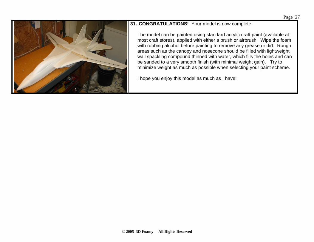
27 31. CONGRATULATIONS! Your model is now complete.
The model can be painted using standard acrylic craft paint (available at most craft stores), applied with either a brush or airbrush. Wipe the foam with rubbing alcohol before painting to remove any grease or dirt. Rough areas such as the canopy and nosecone should be filled with lightweight wall spackling compound thinned with water, which fills the holes and can be sanded to a very smooth finish (with minimal weight gain). Try to minimize weight as much as possible when selecting your paint scheme. I hope you enjoy this model as much as I have!

Page
© 2005 3D Foamy All Rights Reserved
28 Additional Photos
Here are some additional photos of the prototype F-14 Tomcat Park Jet for reference

Page
© 2005 3D Foamy All Rights Reserved
29 Flight Setup
1. The center of gravity location is critical on this model. Make sure to locate it as shown on the plans for your first flights, which is 0.5” ahead of the wing pivot bolts. Depending on how your model is built and set up, you may need to add ballast to the nose to achieve this CG (the prototype model required about 0.75 oz of ballast in the nose). After you’ve gained some experience flying this model and have it trimmed out, the CG can be moved as far aft as the wing pivots for improved maneuverability.
2. Set up the flight controls to provide the following recommended deflections (all dimensions are measured at the root trailing edge):
• Tailerons (pitch): +/- 1.5" (-40% expo) • Tailerons (roll): +/- 1.75" (-40% expo) • Rudder: +/- 7/8" (-30% expo)
Note that these settings will work fine with the wing in all sweep positions. The F-14 is naturally quick in pitch and sluggish in roll with the wings fully unswept, but quick in roll and sluggish in pitch with the wings fully swept aft. However, these control deflections provide a good compromise for both cases so that you don’t have to flick a switch every time you change the wing sweep.
3. Note that the F-14 has a natural aerodynamic tendency to pitch down slightly when the wings are swept from forward to aft. To counter this and keep the airplane trimmed, a custom mix must be set up in the transmitter to automatically add a small amount of up elevator trim as the wing is swept aft. This mix should be set up so that swinging from full forward to full aft sweep provides 1/4" trailing edge up stabilator (about 5% mix rate if using the recommended control deflections). You may need to experiment with your particular model to find the mix that works best, but once you’ve got this adjusted properly you can swing the wings forward and aft at will at any time during the flight and the airplane will always stay perfectly trimmed.
4. Recommended hand launch procedure: Grip the airplane by either the left or right inlet near the CG, set about 75% throttle,
and throw the model moderately hard straight ahead and parallel to the ground. Be careful to keep your hand away from the prop as you throw it! It’s important to launch at less than full throttle to minimize prop torque effects at launch, which could cause the model to roll left immediately after you throw it. Full throttle can be added right after launch once the airplane has some speed.
5. Landing: Remember to ALWAYS release the elevator control right before touchdown during landings, since the forward stabilator tips can dig into to grass or soft ground—which can significantly damage the model and/or stabilator servos! A good hard flare a couple feet off the ground will slow the model down to a very low airspeed, then simply release the elevator and let the model plop gently onto the ground. Also remember to pull the throttle back to zero just before touchdown so that the propeller and/or motor mount is not damaged on landing.

Page
© 2005 3D Foamy All Rights Reserved
30 Repairs Should the inevitable happen, here are some tips:
• Cracks in the foam are fixed with some foam safe CA. Just use accelerator to speed up the process. • Almost anything is repairable. I cracked my plane in 5 pieces, and everyone thought it was finished. 15 minutes later it was
flying. Just take some CA, accelerator and packing tape to the field with you!
If you are using more then 2 bottles of CA a day for fixes… order some more kits!
Best of flying to you, and I hope you have enjoyed building this kit as much as I have designing them!
Remember to send your pictures and videos to post on the website!!!
“I live for this stuff!” 3D Foamy