f-500baf/-c service manual - hoshizaki … · side panel front panel. 8 2. ice making unit. 9...
TRANSCRIPT
Hoshizaki
“A Superior Degree of Reliability”
www.hoshizaki.com
ModelF-500BAF
Self-Contained Flaker
Hoshizaki America, Inc.
Number: 73074Issued: 3-2-1999Revised: 12-26-2003
SERVICE MANUAL
2
IMPORTANTOnly qualified service technicians should attempt to service or maintain thisicemaker. No service or maintenance should be undertaken until the technicianhas thoroughly read this Service Manual.
HOSHIZAKI provides this manual primarily to assist qualified service technicians in theservice and maintenance of the icemaker.
Should the reader have any questions or concerns which have not been satisfactorilyaddressed, please call or write to the HOSHIZAKI Technical Support Department forassistance.
HOSHIZAKI AMERICA, INC.618 Highway 74 SouthPeachtree City, GA 30269
Attn: HOSHIZAKI Technical Support Department
Phone: 1-800-233-1940 Technical Service (770) 487-2331
Fax: (770) 487-3360
Web Site: www.hoshizakiamerica.com
Note: To expedite assistance, all correspondence/communication MUST include thefollowing information:
• Model Number
• Serial Number
• Complete and detailed explanation of the problem

3
Please review this manual. It should be read carefully before the icemaker is serviced ormaintenance operations are performed. Only qualified service technicians should service andmaintain the icemaker. This manual should be made available to the technician prior to serviceor maintenance.
CONTENTSI. Specifications .................................................................................................................... 5
F-500BAF ........................................................................................................................ 5F-500BAF-C..................................................................................................................... 6
II. General Information .......................................................................................................... 71. Construction ................................................................................................................. 7
F-500BAF, F-500BAF-C ............................................................................................. 72. Ice Making Unit ............................................................................................................. 83. Control Box Layout ....................................................................................................... 9
F-500BAF, F-500BAF-C ............................................................................................. 94. Timer Board ................................................................................................................ 10
[a] Solid-State Control .............................................................................................. 10[b] Timer Board ......................................................................................................... 10[c] Sequence ............................................................................................................ 11
III. Technical Information ..................................................................................................... 141. Water Circuit and Refrigerant Circuit ........................................................................... 14
F-500BAF, F-500BAF-C ........................................................................................... 142. Wiring Diagram ........................................................................................................... 15
F-500BAF, F-500BAF-C ........................................................................................... 153. Sequence of Electrical Circuit .................................................................................... 16
F-500BAF, F-500BAF-C ......................................................................................... 164. Timing Chart ............................................................................................................... 215. Performance Data ....................................................................................................... 24
F-500BAF ................................................................................................................ 24F-500BAF-C ............................................................................................................. 25
IV. Service Diagnosis .......................................................................................................... 261. No Ice Production ....................................................................................................... 262. Low Ice Production ..................................................................................................... 293. Other ........................................................................................................................... 30
V. Removal and Replacement of Components .................................................................. 311. Service for Refrigerant Lines ...................................................................................... 31
[a] Refrigerant Recovery........................................................................................... 31[b] Evacuation and Recharge [R-404A] .................................................................... 31
2. Brazing ....................................................................................................................... 323. Removal and Replacement of Compressor ................................................................ 334. Removal and Replacement of Drier ........................................................................... 345. Removal and Replacement of Expansion Valve......................................................... 356. Removal and Replacement of Evaporator Assembly ................................................ 367. Removal and Replacement of Fan Motor ................................................................... 408. Removal and Replacement of Control Water Valve .................................................... 40

4
VI. Cleaning and Maintenance .......................................................................................... 411. Preparing the Icemaker for Long Storage ................................................................... 412. Cleaning and Sanitizing Instructions .......................................................................... 42
[a] Cleaning Solution ................................................................................................ 42[b] Cleaning Procedure ............................................................................................ 42[c] Sanitizing Solution............................................................................................... 43[d] Sanitizing Procedure - Initial ................................................................................ 44[e] Sanitizing Procedure - Final ................................................................................ 44
3. Maintenance Instructions ............................................................................................ 46
5
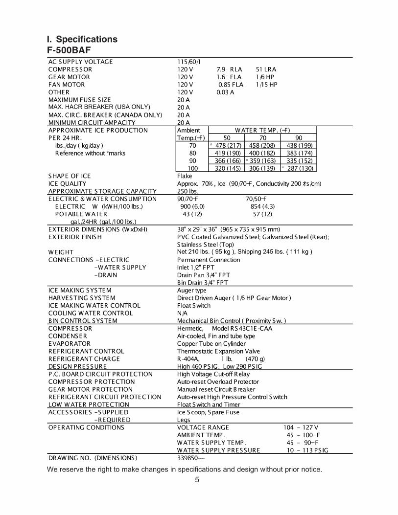
I. SpecificationsF-500BAFAC SUPPLY VOLTAGE 115/60/1COMPRESSOR 120 V 7.9 RLA 51 LRAGEAR MOTOR 120 V 1.6 FLA 1/6 HPFAN MOTOR 120 V 0.85 FLA 1/15 HPOTHER 120 V 0.03 AMAXIMUM FUSE S IZE 20 AMAX. HACR BREAKER (USA ONLY) 20 AMAX. CIRC. BREAKER (CANADA ONLY) 20 AMINIMUM CIRCUIT AMPACITY 20 AAPPROXIMATE ICE PRODUCTION Ambient WATER TEMP. ( Fー)PER 24 HR. Temp.( Fー) 50 70 90 lbs./day ( kg/day ) 70 * 478 (217) 458 (208) 438 (199) Reference without *marks 80 419 (190) 400 (182) 383 (174)
90 366 (166) * 359 (163) 335 (152)100 320 (145) 306 (139) * 287 (130)
SHAPE OF ICE FlakeICE QUALITY Approx. 70% , Ice (90/70 Fー, Conductivity 200 オs/cm)APPROXIMATE STORAGE CAPACITY 250 lbs.ELECTRIC & WATER CONSUMPTION 90/70 Fー 70/50 Fー ELECTRIC W (kWH/100 lbs.) 900 (6.0) 854 (4.3) POTABLE WATER 43 (12) 57 (12) gal./24HR (gal./100 lbs.)EXTERIOR DIMENSIONS (WxDxH) 38" x 29" x 36" (965 x 735 x 915 mm)EXTERIOR FINISH PVC Coated Galvanized Steel; Galvanized Steel (Rear);
Stainless Steel (Top)WEIGHT Net 210 lbs. ( 95 kg ), Shipping 245 lbs. ( 111 kg )CONNECTIONS - ELECTRIC Permanent Connection - WATER SUPPLY Inlet 1/2" FPT - DRAIN Drain Pan 3/4" FPT
Bin Drain 3/4" FPTICE MAKING SYSTEM Auger typeHARVESTING SYSTEM Direct Driven Auger ( 1/6 HP Gear Motor )ICE MAKING WATER CONTROL Float SwitchCOOLING WATER CONTROL N/ABIN CONTROL SYSTEM Mechanical Bin Control ( Proximity Sw. )COMPRESSOR Hermetic, Model RS43C1E-CAACONDENSER Air-cooled, Fin and tube typeEVAPORATOR Copper Tube on CylinderREFRIGERANT CONTROL Thermostatic Expansion ValveREFRIGERANT CHARGE R-404A, 1 lb. (470 g)DESIGN PRESSURE High 460 PS IG, Low 290 PS IGP.C. BOARD CIRCUIT PROTECTION High Voltage Cut-off RelayCOMPRESSOR PROTECTION Auto-reset Overload ProtectorGEAR MOTOR PROTECTION Manual reset Circuit Breaker REFRIGERANT CIRCUIT PROTECTION Auto-reset High Pressure Control SwitchLOW WATER PROTECTION Float Switch and TimerACCESSORIES - SUPPLIED Ice Scoop, Spare Fuse - REQUIRED LegsOPERATING CONDITIONS VOLTAGE RANGE 104 - 127 V
AMBIENT TEMP. 45 - 100 ーFWATER SUPPLY TEMP. 45 - 90 ーFWATER SUPPLY PRESSURE 10 - 113 PS IG
DRAWING NO. (DIMENSIONS) 339850---
We reserve the right to make changes in specifications and design without prior notice.
6
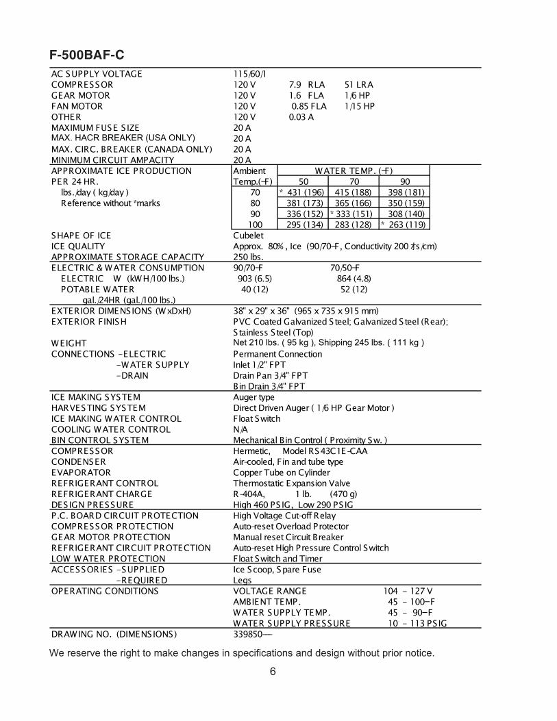
F-500BAF-CAC SUPPLY VOLTAGE 115/60/1COMPRESSOR 120 V 7.9 RLA 51 LRAGEAR MOTOR 120 V 1.6 FLA 1/6 HPFAN MOTOR 120 V 0.85 FLA 1/15 HPOTHER 120 V 0.03 AMAXIMUM FUSE S IZE 20 AMAX. HACR BREAKER (USA ONLY) 20 AMAX. CIRC. BREAKER (CANADA ONLY) 20 AMINIMUM CIRCUIT AMPACITY 20 AAPPROXIMATE ICE PRODUCTION Ambient WATER TEMP. ( Fー)PER 24 HR. Temp.( Fー) 50 70 90 lbs./day ( kg/day ) 70 * 431 (196) 415 (188) 398 (181) Reference without *marks 80 381 (173) 365 (166) 350 (159)
90 336 (152) * 333 (151) 308 (140)100 295 (134) 283 (128) * 263 (119)
SHAPE OF ICE CubeletICE QUALITY Approx. 80% , Ice (90/70 Fー, Conductivity 200 オs/cm)APPROXIMATE STORAGE CAPACITY 250 lbs.ELECTRIC & WATER CONSUMPTION 90/70 Fー 70/50 Fー ELECTRIC W (kWH/100 lbs.) 903 (6.5) 864 (4.8) POTABLE WATER 40 (12) 52 (12) gal./24HR (gal./100 lbs.)EXTERIOR DIMENSIONS (WxDxH) 38" x 29" x 36" (965 x 735 x 915 mm)EXTERIOR FINISH PVC Coated Galvanized Steel; Galvanized Steel (Rear);
Stainless Steel (Top)WEIGHT Net 210 lbs. ( 95 kg ), Shipping 245 lbs. ( 111 kg )CONNECTIONS - ELECTRIC Permanent Connection - WATER SUPPLY Inlet 1/2" FPT - DRAIN Drain Pan 3/4" FPT
Bin Drain 3/4" FPTICE MAKING SYSTEM Auger typeHARVESTING SYSTEM Direct Driven Auger ( 1/6 HP Gear Motor )ICE MAKING WATER CONTROL Float SwitchCOOLING WATER CONTROL N/ABIN CONTROL SYSTEM Mechanical Bin Control ( Proximity Sw. )COMPRESSOR Hermetic, Model RS43C1E-CAACONDENSER Air-cooled, Fin and tube typeEVAPORATOR Copper Tube on CylinderREFRIGERANT CONTROL Thermostatic Expansion ValveREFRIGERANT CHARGE R-404A, 1 lb. (470 g)DESIGN PRESSURE High 460 PS IG, Low 290 PS IGP.C. BOARD CIRCUIT PROTECTION High Voltage Cut-off RelayCOMPRESSOR PROTECTION Auto-reset Overload ProtectorGEAR MOTOR PROTECTION Manual reset Circuit Breaker REFRIGERANT CIRCUIT PROTECTION Auto-reset High Pressure Control SwitchLOW WATER PROTECTION Float Switch and TimerACCESSORIES - SUPPLIED Ice Scoop, Spare Fuse - REQUIRED LegsOPERATING CONDITIONS VOLTAGE RANGE 104 - 127 V
AMBIENT TEMP. 45 - 100 ーFWATER SUPPLY TEMP. 45 - 90 ーFWATER SUPPLY PRESSURE 10 - 113 PS IG
DRAWING NO. (DIMENSIONS) 339850---
We reserve the right to make changes in specifications and design without prior notice.
7
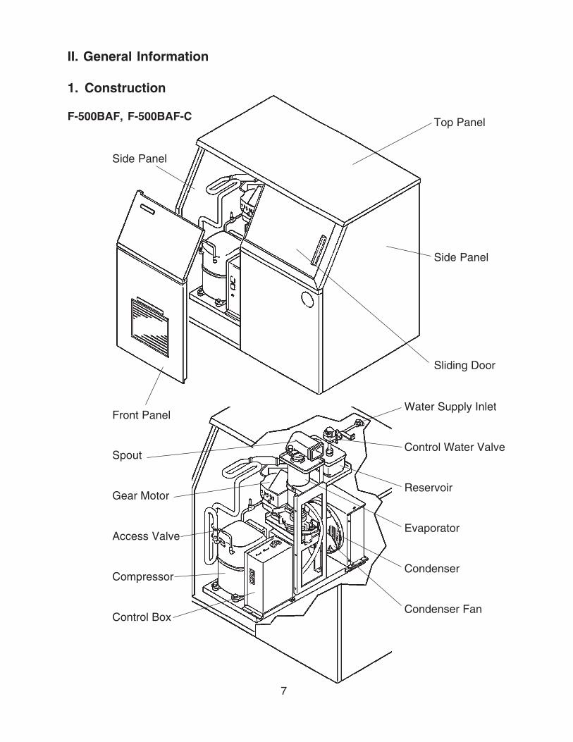
II. General Information
1. Construction
F-500BAF, F-500BAF-C Top Panel
Side Panel
Sliding Door
Water Supply Inlet
Control Water Valve
Reservoir
Evaporator
Condenser
Condenser Fan
Spout
Gear Motor
Access Valve
Compressor
Control Box
Side Panel
Front Panel

8
2. Ice Making Unit
9
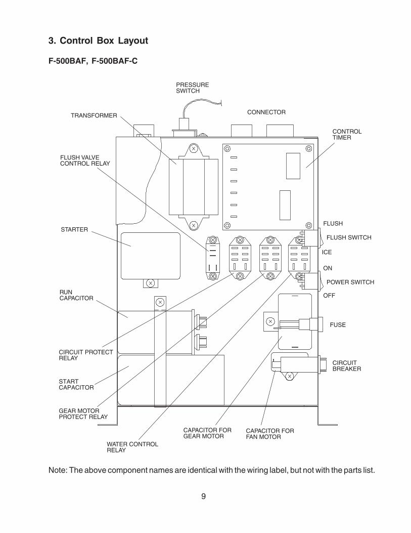
CONTROLTIMER
CONNECTOR
PRESSURESWITCH
TRANSFORMER
WATER CONTROLRELAY
FLUSH
FLUSH SWITCH
ICE
FUSE
CIRCUITBREAKER
OFF
ON
POWER SWITCH
CIRCUIT PROTECTRELAY
GEAR MOTORPROTECT RELAY
CAPACITOR FORGEAR MOTOR
CAPACITOR FORFAN MOTOR
STARTCAPACITOR
RUNCAPACITOR
STARTER
FLUSH VALVECONTROL RELAY
Note: The above component names are identical with the wiring label, but not with the parts list.
3. Control Box Layout
F-500BAF, F-500BAF-C
10
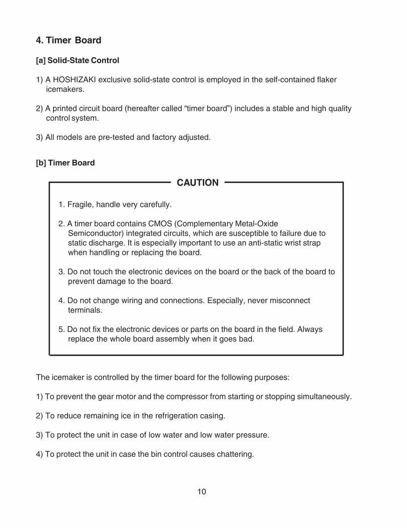
4. Timer Board
[a] Solid-State Control
1) A HOSHIZAKI exclusive solid-state control is employed in the self-contained flakericemakers.
2) A printed circuit board (hereafter called “timer board”) includes a stable and high qualitycontrol system.
3) All models are pre-tested and factory adjusted.
[b] Timer Board
CAUTION
1. Fragile, handle very carefully.
2. A timer board contains CMOS (Complementary Metal-OxideSemiconductor) integrated circuits, which are susceptible to failure due tostatic discharge. It is especially important to use an anti-static wrist strapwhen handling or replacing the board.
3. Do not touch the electronic devices on the board or the back of the board toprevent damage to the board.
4. Do not change wiring and connections. Especially, never misconnectterminals.
5. Do not fix the electronic devices or parts on the board in the field. Alwaysreplace the whole board assembly when it goes bad.
The icemaker is controlled by the timer board for the following purposes:
1) To prevent the gear motor and the compressor from starting or stopping simultaneously.
2) To reduce remaining ice in the refrigeration casing.
3) To protect the unit in case of low water and low water pressure.
4) To protect the unit in case the bin control causes chattering.
11
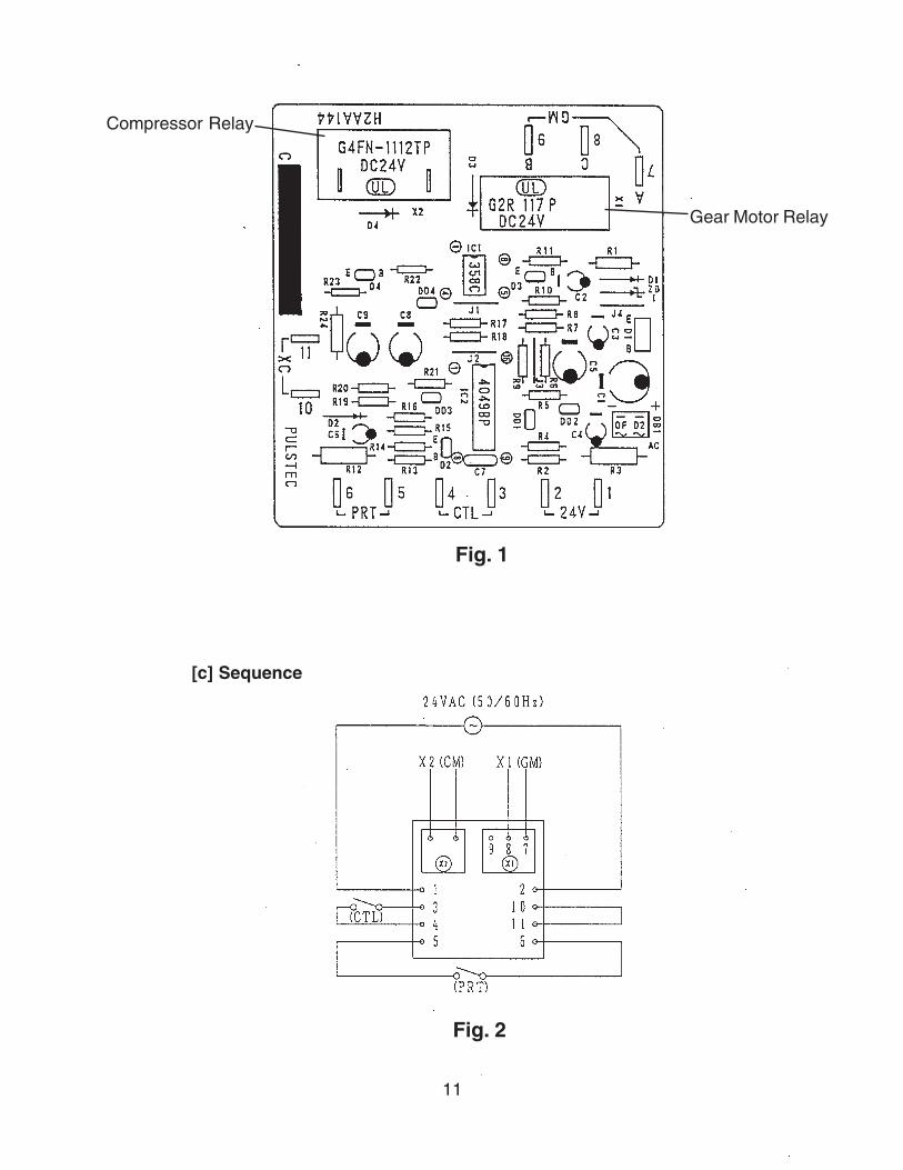
Fig. 1
[c] Sequence
Fig. 2
Gear Motor Relay
Compressor Relay

12
Fig. 3
EDOCTRAP 10-503734LEDOM 10C441AA2HGNITAR zH06/05CAV42
1T .ces51±062T .ces22±093T .ces54±0514T sselro.ces15T %07±.ces7.66T %07±.ces7.6
13
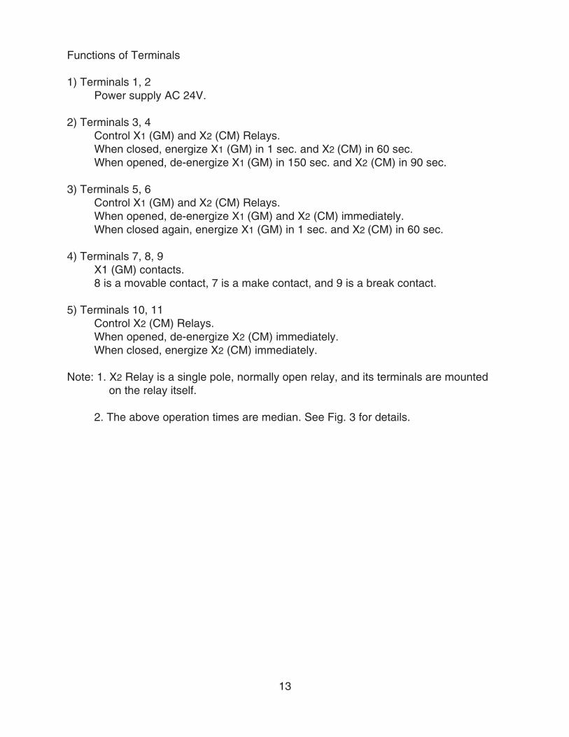
Functions of Terminals
1) Terminals 1, 2Power supply AC 24V.
2) Terminals 3, 4Control X1 (GM) and X2 (CM) Relays.When closed, energize X1 (GM) in 1 sec. and X2 (CM) in 60 sec.When opened, de-energize X1 (GM) in 150 sec. and X2 (CM) in 90 sec.
3) Terminals 5, 6Control X1 (GM) and X2 (CM) Relays.When opened, de-energize X1 (GM) and X2 (CM) immediately.When closed again, energize X1 (GM) in 1 sec. and X2 (CM) in 60 sec.
4) Terminals 7, 8, 9X1 (GM) contacts.8 is a movable contact, 7 is a make contact, and 9 is a break contact.
5) Terminals 10, 11Control X2 (CM) Relays.When opened, de-energize X2 (CM) immediately.When closed, energize X2 (CM) immediately.
Note: 1. X2 Relay is a single pole, normally open relay, and its terminals are mountedon the relay itself.
2. The above operation times are median. See Fig. 3 for details.
14
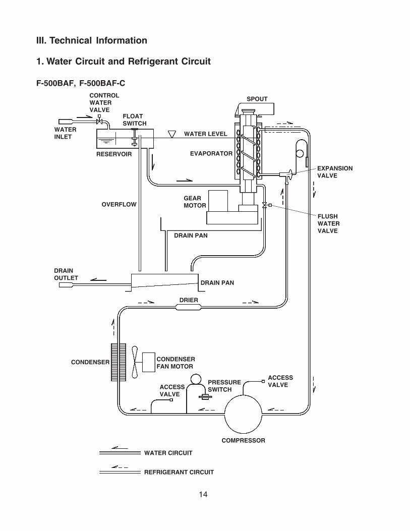
III. Technical Information
1. Water Circuit and Refrigerant Circuit
F-500BAF, F-500BAF-C
SPOUTCONTROLWATERVALVE
FLOATSWITCH
RESERVOIR
OVERFLOWGEARMOTOR
WATER LEVEL
EVAPORATOR
WATERINLET
DRIER
CONDENSER CONDENSERFAN MOTOR
PRESSURESWITCH
COMPRESSOR
WATER CIRCUIT
REFRIGERANT CIRCUIT
ACCESSVALVE
DRAINOUTLET
DRAIN PAN
DRAIN PAN
FLUSHWATERVALVE
ACCESSVALVE
EXPANSIONVALVE
15
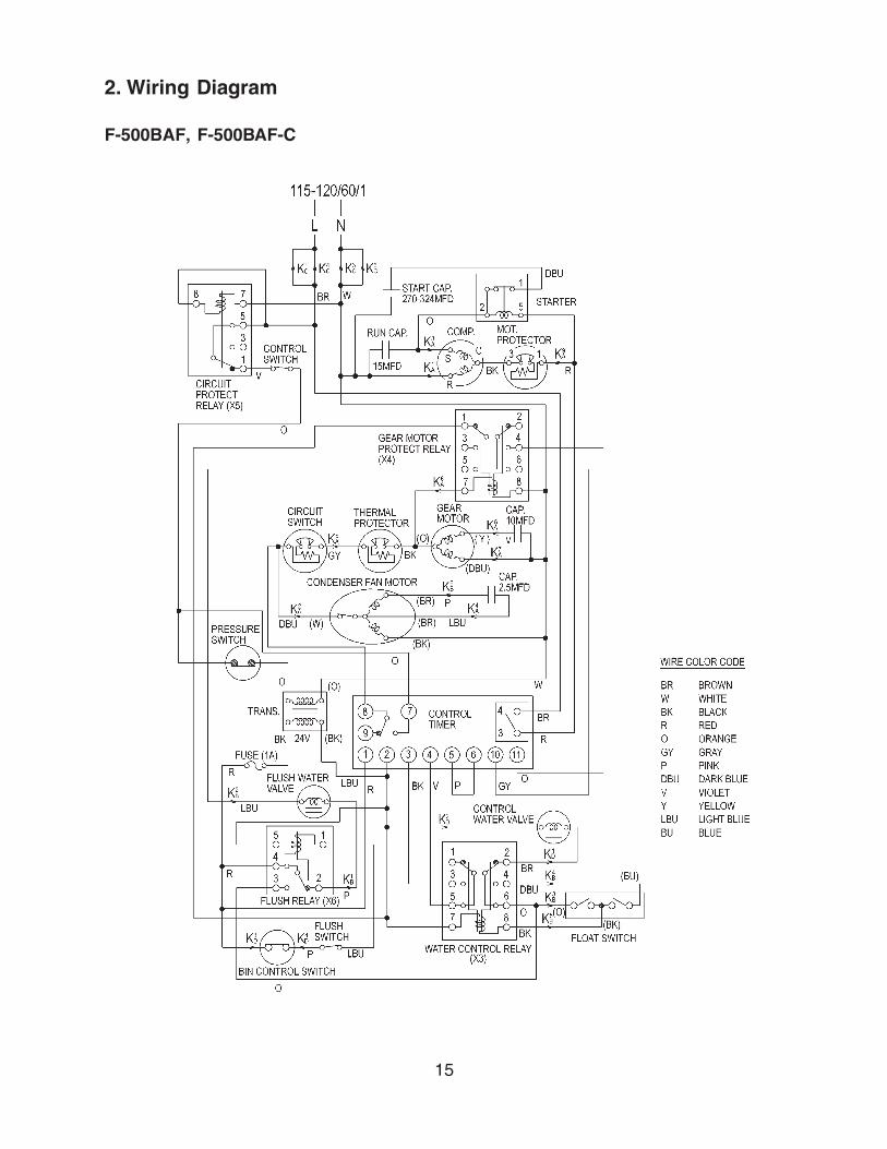
2. Wiring Diagram
F-500BAF, F-500BAF-C

16
�������������
�� �� �
� �
� �
�
�����������������������
�������������
�
!� ������������� ���"�#$
�
�����
�
�!
�
�
�
%
�
�
�
"
�
�
&������������������������"�
�
��
&��������
���� �#$ �
�
�� �
� "�
��
�
'�
��
%
����������������
�������������
&� !
��� � � �
�$!���������#$
�!�� �
�!��!��
�! �
�!
"�
���$������#��������
��
���$!���������������
�
� � " �
� "
�
�
'
�
!�
�
�&��%! �
�!�
������������
������
� ���
�������������%��%�
!�
$!�
�
!
�!��
�! �#�����������
�
�
"
�
�
�
$
"!
�!
!
�����������������������
�$
! �"% �! �
#����������%��%�
#�������
�
�!
�!�
"
� �
!
#���������������
�$ "
$
!�����������������
�
#����������
�!�
���
��������
�#$
�
$!�
�������
�
�
�
�
!��! ��&��$!�%��!�!�
!���������!��� ��$����&�&������ $�� �!���%�������������&���!���!���
�������������$�
(F-500BAF(-C))
3. Sequence of Electrical Circuit
F-500BAF, F-500BAF-C [a] When power switch is moved to "ON" position and flush switch to "ICE" position, water starts to be supplied to reservoir.
17
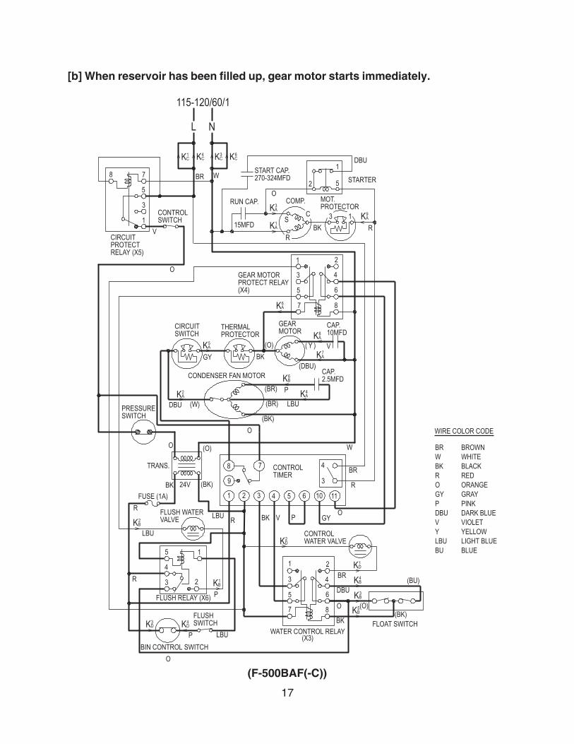
[b] When reservoir has been filled up, gear motor starts immediately.
�������������
�� �� �
� �
� �
�
�����������������������
�������������
�
!� ������������� ���"�#$
�
�����
�
�!
�
�
�
%
�
�
�
"
�
�
&������������������������"�
�
��
&��������
���� �#$ �
�
�� �
� "�
��
�
'�
��
%
����������������
�������������
&� !
��� � � �
�$!���������#$
�!�� �
�!��!��
�! �
�!
"�
���$������#��������
��
���$!���������������
�
� � " �
� "
�
�
'
�
!�
�
�&��%! �
�!�
������������
������
� ���
�������������%��%�
!�
$!�
�
!
�!��
�! �#�����������
�
�
"
�
�
�
$
"!
�!
!
�����������������������
�$
! �"% �! �
#����������%��%�
#�������
�
�!
�!�
"
� �
!
#���������������
�$ "
$
!�����������������
�
#����������
�!�
���
��������
�#$
�
$!�
�������
�
�
�
�
!��! ��&��$!�%��!�!�
!���������!��� ��$����&�&������ $�� �!���%�������������&���!���!���
�������������$�
(F-500BAF(-C))
18
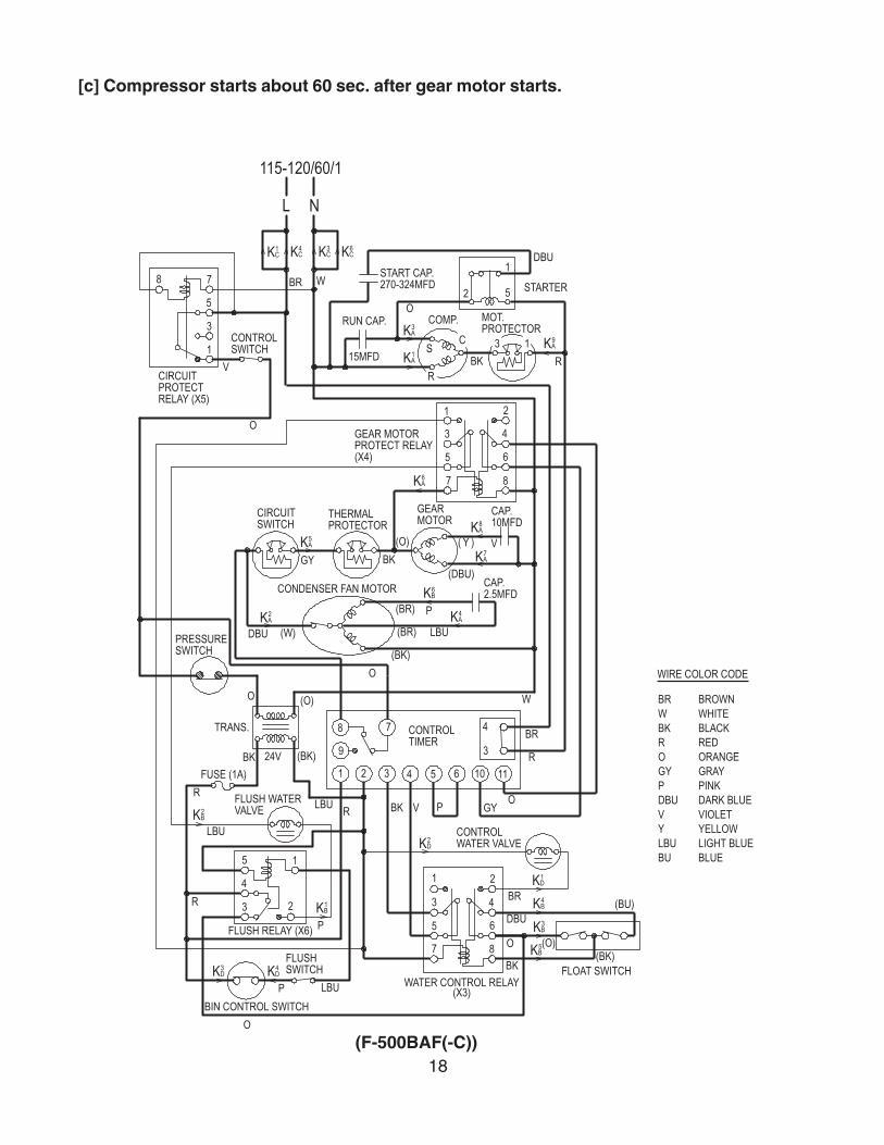
[c] Compressor starts about 60 sec. after gear motor starts.
�������������
�� �� �
� �
� �
�
�����������������������
�������������
�
!� ������������� ���"�#$
�
�����
�
�!
�
�
�
%
�
�
�
"
�
�
&������������������������"�
�
��
&��������
���� �#$ �
�
�� �
� "�
��
�
'�
��
%
����������������
�������������
&� !
��� � � �
�$!���������#$
�!�� �
�!��!��
�! �
�!
"�
���$������#��������
��
���$!���������������
�
� � " �
� "
�
�
'
�
!�
�
�&��%! �
�!�
������������
������
� ���
�������������%��%�
!�
$!�
�
!
�!��
�! �#�����������
�
�
"
�
�
�
$
"!
�!
!
�����������������������
�$
! �"% �! �
#����������%��%�
#�������
�
�!
�!�
"
� �
!
#���������������
�$ "
$
!�����������������
�
#����������
�!�
���
��������
�#$
�
$!�
�������
�
�
�
�
!��! ��&��$!�%��!�!�
!���������!��� ��$����&�&������ $�� �!���%�������������&���!���!���
�������������$�
(F-500BAF(-C))
19
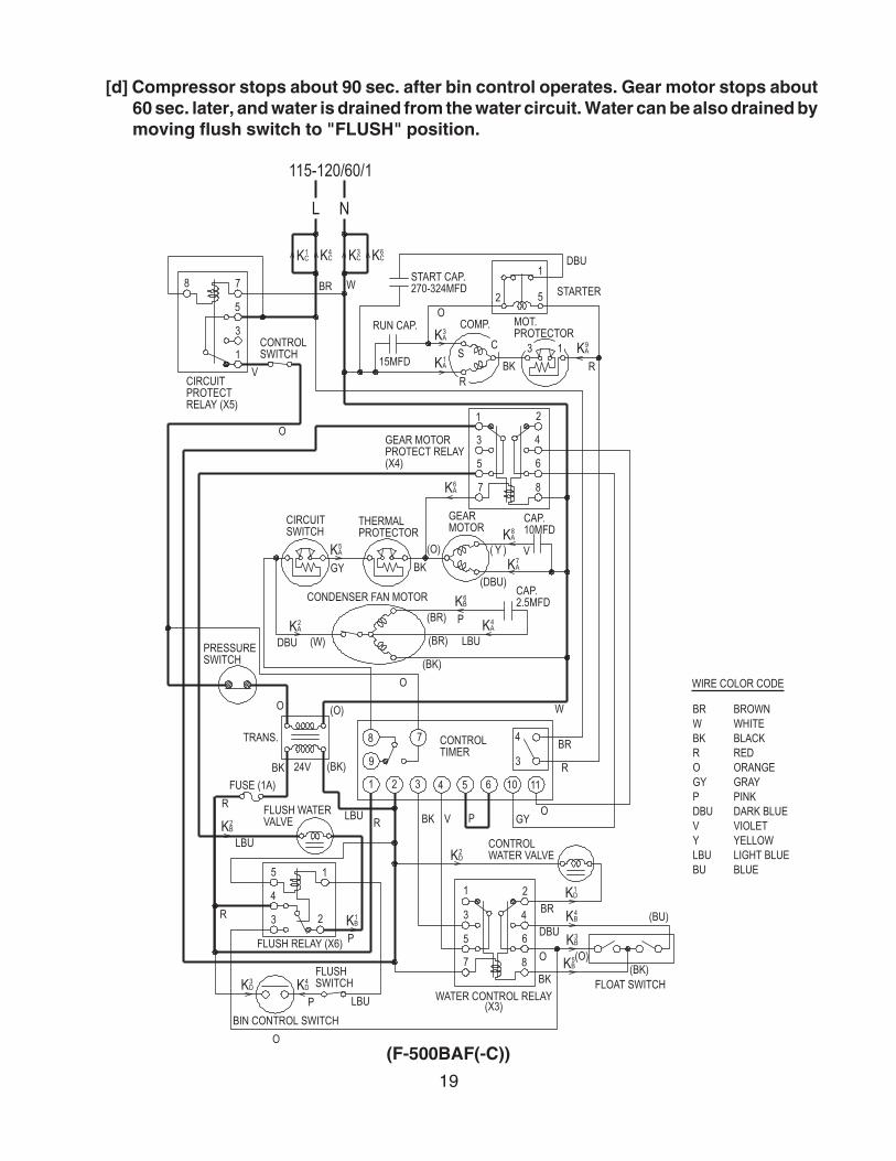
[d] Compressor stops about 90 sec. after bin control operates. Gear motor stops about60 sec. later, and water is drained from the water circuit. Water can be also drained bymoving flush switch to "FLUSH" position.
�������������
�� �� �
� �
� �
�
�����������������������
�������������
�
!� ������������� ���"�#$
�
�����
�
�!
�
�
�
%
�
�
�
"
�
�
&������������������������"�
�
��
&��������
���� �#$ �
�
�� �
� "�
��
�
'�
��
%
����������������
�������������
&� !
��� � � �
�$!���������#$
�!�� �
�!��!��
�! �
�!
"�
���$������#��������
��
���$!���������������
�
� � " �
� "
�
�
'
�
!�
�
�&��%! �
�!�
������������
������
� ���
�������������%��%�
!�
$!�
�
!
�!��
�! �#�����������
�
�
"
�
�
�
$
"!
�!
!
�����������������������
�$
! �"% �! �
#����������%��%�
#�������
�
�!
�!�
"
� �
!
#���������������
�$ "
$
!�����������������
�
#����������
�!�
���
��������
�#$
�
$!�
�������
�
�
�
�
!��! ��&��$!�%��!�!�
!���������!��� ��$����&�&������ $�� �!���%�������������&���!���!���
�������������$�
(F-500BAF(-C))

20
[e] When 208 - 230V are supplied to the power supply due to miswiring, circuit protectrelay operates, and the icemaker does not run.
�������������
�� �� �
� �
� �
�
�����������������������
�������������
�
!� ������������� ���"�#$
�
�����
�
�!
�
�
�
%
�
�
�
"
�
�
&������������������������"�
�
��
&��������
���� �#$ �
�
�� �
� "�
��
�
'�
��
%
����������������
�������������
&� !
��� � � �
�$!���������#$
�!�� �
�!��!��
�! �
�!
"�
���$������#��������
��
���$!���������������
�
� � " �
� "
�
�
'
�
!�
�
�&��%! �
�!�
������������
������
� ���
�������������%��%�
!�
$!�
�
!
�!��
�! �#�����������
�
�
"
�
�
�
$
"!
�!
!
�����������������������
�$
! �"% �! �
#����������%��%�
#�������
�
�!
�!�
"
� �
!
#���������������
�$ "
$
!�����������������
�
#����������
�!�
���
��������
�#$
�
$!�
�������
�
�
�
�
!��! ��&��$!�%��!�!�
!���������!��� ��$����&�&������ $�� �!���%�������������&���!���!���
�������������$�
(F-500BAF(-C))
21
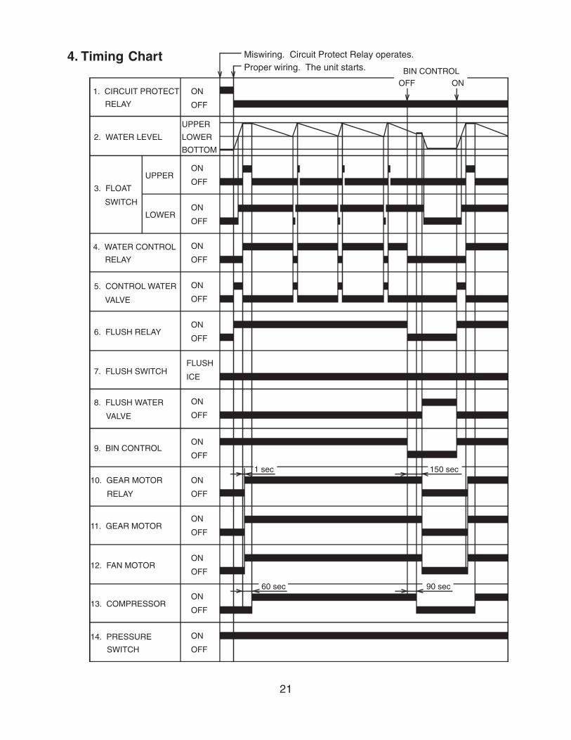
Miswiring. Circuit Protect Relay operates.Proper wiring. The unit starts. BIN CONTROL
OFF ON1. CIRCUIT PROTECT
RELAY
2. WATER LEVEL
3. FLOAT
SWITCH
UPPER
LOWER
4. WATER CONTROL
RELAY
5. CONTROL WATER
VALVE
6. FLUSH RELAY
7. FLUSH SWITCH
8. FLUSH WATER
VALVE
9. BIN CONTROL
10. GEAR MOTOR
RELAY
11. GEAR MOTOR
12. FAN MOTOR
13. COMPRESSOR
14. PRESSURE
SWITCH
ON
OFF
ON
OFF
ON
OFF
ON
OFF
ON
OFF
FLUSH
ICE
ON
OFF
ON
OFF
ON
OFF
ON
OFF
ON
OFF
ON
OFF
ON
OFF
1 sec
60 sec
150 sec
90 sec
UPPER
LOWER
BOTTOM
ON
OFF
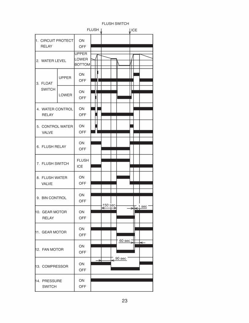
4. Timing Chart
22
1. CIRCUIT PROTECT
RELAY
2. WATER LEVEL
3. FLOAT
SWITCH
UPPER
LOWER
4. WATER CONTROL
RELAY
5. CONTROL WATER
VALVE
6. FLUSH RELAY
7. FLUSH SWITCH
8. FLUSH WATER
VALVE
9. BIN CONTROL
10. GEAR MOTOR
RELAY
11. GEAR MOTOR
12. FAN MOTOR
13. COMPRESSOR
14. PRESSURE
SWITCH
ON
OFF
ON
OFF
ON
OFF
ON
OFF
ON
OFF
FLUSH
ICE
ON
OFF
ON
OFF
ON
OFF
ON
OFF
ON
OFF
ON
OFF
ON
OFF
UPPER
LOWER
BOTTOM
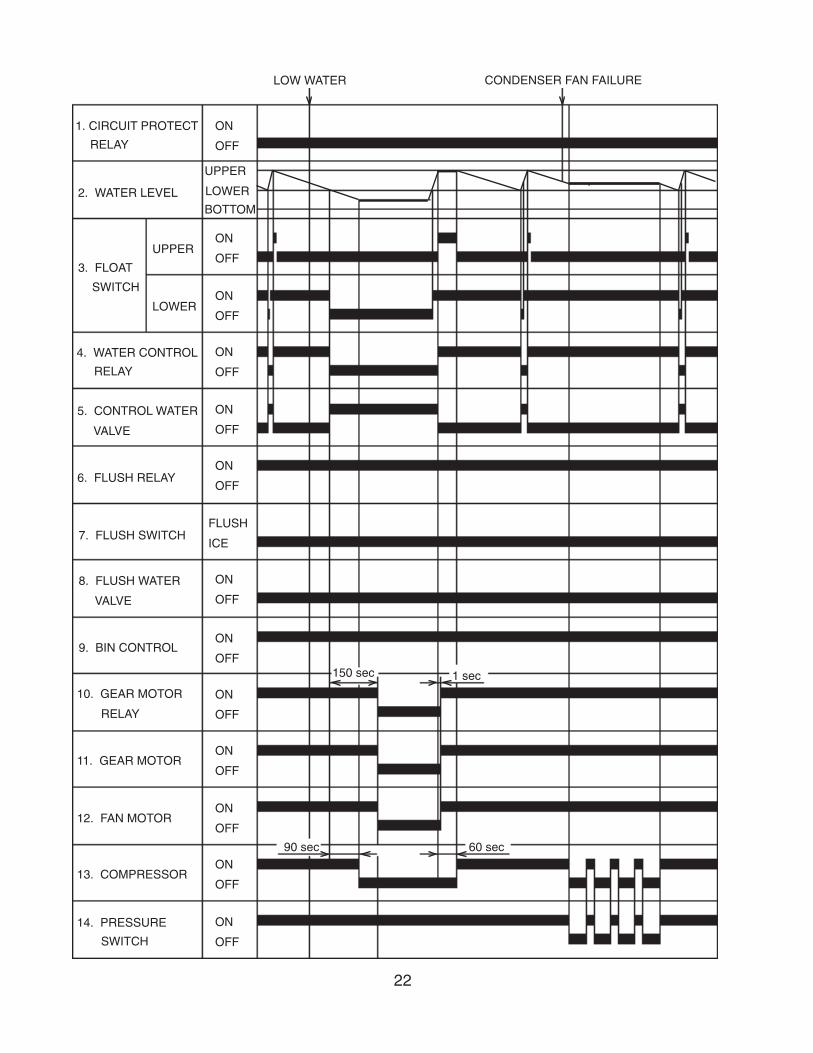
LOW WATER CONDENSER FAN FAILURE
150 sec 1 sec
90 sec 60 sec
ON
OFF
23
1. CIRCUIT PROTECT
RELAY
2. WATER LEVEL
3. FLOAT
SWITCH
UPPER
LOWER
4. WATER CONTROL
RELAY
5. CONTROL WATER
VALVE
6. FLUSH RELAY
7. FLUSH SWITCH
8. FLUSH WATER
VALVE
9. BIN CONTROL
10. GEAR MOTOR
RELAY
11. GEAR MOTOR
12. FAN MOTOR
13. COMPRESSOR
14. PRESSURE
SWITCH
ON
OFF
ON
OFF
ON
OFF
ON
OFF
ON
OFF
FLUSH
ICE
ON
OFF
ON
OFF
ON
OFF
ON
OFF
ON
OFF
ON
OFF
ON
OFF
UPPER
LOWERBOTTOM
FLUSH SWITCH
FLUSH ICE
ON
OFF
150 sec 1 sec
90 sec
60 sec
24
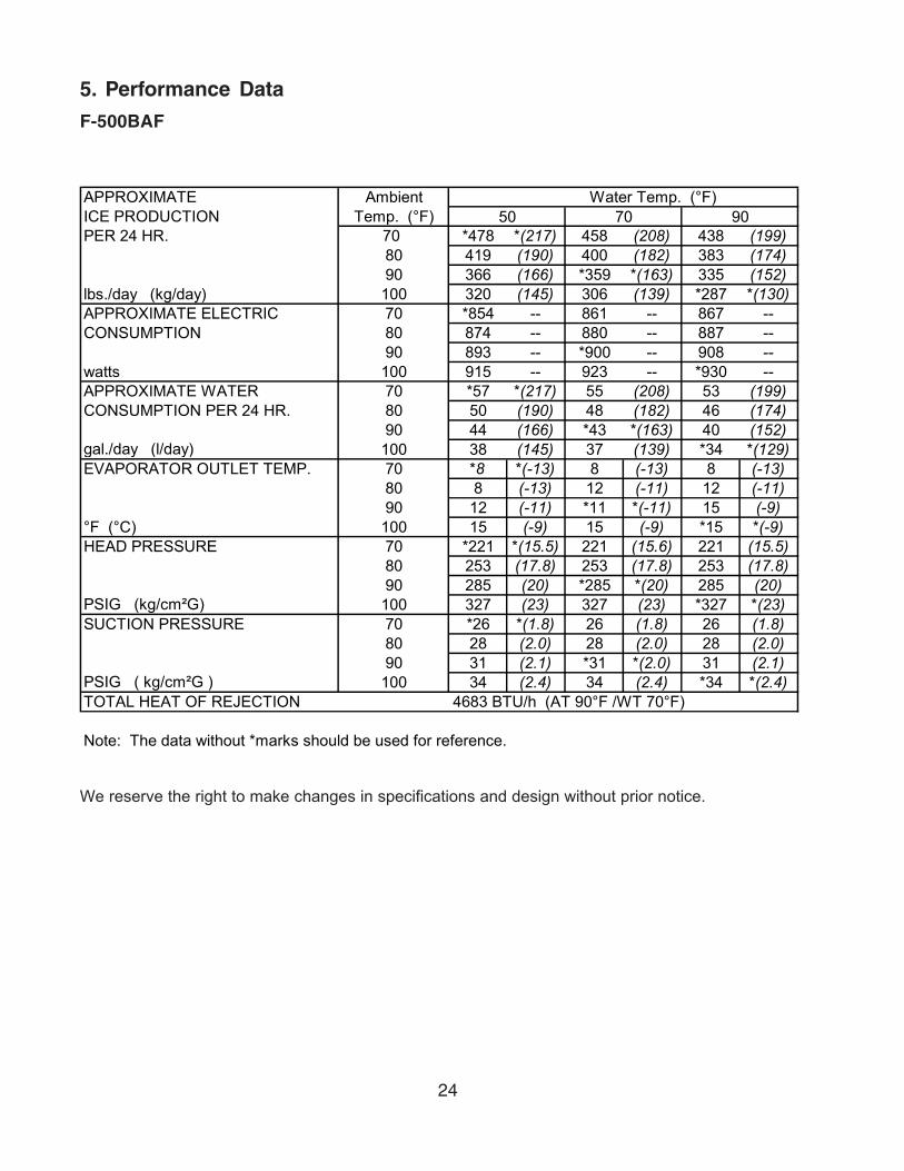
5. Performance Data
F-500BAF
APPROXIMATE Ambient Water Temp. (°F)ICE PRODUCTION Temp. (°F)PER 24 HR. 70 *478 *(217) 458 (208) 438 (199)
80 419 (190) 400 (182) 383 (174)90 366 (166) *359 *(163) 335 (152)
lbs./day (kg/day) 100 320 (145) 306 (139) *287 *(130)APPROXIMATE ELECTRIC 70 *854 -- 861 -- 867 --CONSUMPTION 80 874 -- 880 -- 887 --
90 893 -- *900 -- 908 --watts 100 915 -- 923 -- *930 --APPROXIMATE WATER 70 *57 *(217) 55 (208) 53 (199)CONSUMPTION PER 24 HR. 80 50 (190) 48 (182) 46 (174)
90 44 (166) *43 *(163) 40 (152)gal./day (l/day) 100 38 (145) 37 (139) *34 *(129)EVAPORATOR OUTLET TEMP. 70 *8 *(-13) 8 (-13) 8 (-13)
80 8 (-13) 12 (-11) 12 (-11)90 12 (-11) *11 *(-11) 15 (-9)
°F (°C) 100 15 (-9) 15 (-9) *15 *(-9)HEAD PRESSURE 70 *221 *(15.5) 221 (15.6) 221 (15.5)
80 253 (17.8) 253 (17.8) 253 (17.8)90 285 (20) *285 *(20) 285 (20)
PSIG (kg/cm²G) 100 327 (23) 327 (23) *327 *(23)SUCTION PRESSURE 70 *26 *(1.8) 26 (1.8) 26 (1.8)
80 28 (2.0) 28 (2.0) 28 (2.0)90 31 (2.1) *31 *(2.0) 31 (2.1)
PSIG ( kg/cm²G ) 100 34 (2.4) 34 (2.4) *34 *(2.4)TOTAL HEAT OF REJECTION 4683 BTU/h (AT 90°F /WT 70°F)
Note: The data without *marks should be used for reference.
50 70 90
We reserve the right to make changes in specifications and design without prior notice.

25
F-500BAF-C
APPROXIMATE Ambient Water Temp. (°F)ICE PRODUCTION Temp. (°F)PER 24 HR. 70 *431 *(196) 415 (188) 398 (181)
80 381 (173) 365 (166) 350 (159)90 336 (152) *333 *(151) 308 (140)
lbs./day (kg/day) 100 295 (134) 283 (128) *263 *(119)APPROXIMATE ELECTRIC 70 *864 -- 869 -- 875 --CONSUMPTION 80 880 -- 886 -- 891 --
90 897 -- *902 -- 907 --watts 100 912 -- 917 -- *922 --APPROXIMATE WATER 70 *52 *(196) 50 (188) 48 (181)CONSUMPTION PER 24 HR. 80 46 (173) 44 (166) 42 (159)
90 40 (152) *40 *(151) 37 (140)gal./day (l/day) 100 35 (134) 34 (128) *32 *(119)EVAPORATOR OUTLET TEMP. 70 *9 *(-13) 9 (-13) 9 (-13)
80 9 (-13) 12 (-11) 12 (-11)90 12 (-11) *12 *(-11) 15 (-9)
°F (°C) 100 15 (-9) 15 (-9) *15 *(-9)HEAD PRESSURE 70 *225 *(15.8) 225 (15.8) 225 (15.8)
80 258 (18.1) 258 (18.1) 258 (18.1)90 292 (20.5) *292 *(20.5) 292 (20.5)
PSIG (kg/cm²G) 100 332 (23.3) 332 (23.3) *332 *(23.3)SUCTION PRESSURE 70 *27 *(1.9) 27 (1.9) 27 (1.9)
80 30 (2.1) 30 (2.1) 30 (2.1)90 32 (2.3) *32 *(2.3) 32 (2.3)
PSIG ( kg/cm²G ) 100 35 (2.5) 35 (2.5) *35 *(2.5)TOTAL HEAT OF REJECTION 4724 BTU/h (AT 90°F /WT 70°F)
Note: The data without *marks should be used for reference.
50 70 90
We reserve the right to make changes in specifications and design without prior notice.
26
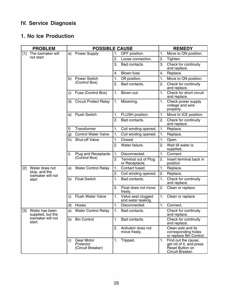
IV. Service Diagnosis
1. No Ice Production
PROBLEM POSSIBLE CAUSE REMEDY[1] The icemaker will
not start.a) Power Supply 1. OFF position. 1. Move to ON position.
2. Loose connection. 2. Tighten.3. Bad contacts. 3. Check for continuity
and replace.4. Blown fuse. 4. Replace.
b) Power Switch(Control Box)
1. Off position. 1. Move to ON position.2. Bad contacts. 2. Check for continuity
and replace.c) Fuse (Control Box) 1. Blown out. 1. Check for short circuit
and replace.d) Circuit Protect Relay 1. Miswiring. 1. Check power supply
voltage and wireproperly.
e) Flush Switch 1. FLUSH position. 1. Move to ICE position.2. Bad contacts. 2. Check for continuity
and replace.f) Transformer 1. Coil winding opened. 1. Replace.g) Control Water Valve 1. Coil winding opened. 1. Replace.h) Shut-off Valve 1. Closed. 1. Open.
2. Water failure. 2. Wait till water issupplied.
i) Plug and Receptacle(Control Box)
1. Disconnected. 1. Connect.2. Terminal out of Plug
or Receptacle.2. Insert terminal back in
position[2] Water does not
stop, and theicemaker will notstart
a) Water Control Relay 1. Contact fused. 1. Replace.2. Coil winding opened. 2. Replace.
b) Float Switch 1. Bad contacts. 1. Check for continuityand replace.
2. Float does not movefreely.
2. Clean or replace.
c) Flush Water Valve 1. Valve seat cloggedand water leaking.
1. Clean or replace
d) Hoses 1. Disconnected. 1. Connect.[3] Water has been
supplied, but theicemaker will notstart.
a) Water Control Relay 1. Bad contacts. Check for continuityand replace.
b) Bin Control 1. Bad contacts. Check for continuityand replace.
2. Activator does notmove freely.
Clean axle and itscorresponding holesor replace Bin Control.
c) Gear MotorProtector(Circuit Breaker)
1. Tripped. 1. Find out the cause,get rid of it, and pressReset Button onCircuit Breaker.

27
PROBLEM POSSIBLE CAUSE REMEDYd) Gear Motor Protect
Relay1. Coil winding opened. 1. Replace.2. Bad contacts. 2. Check for continuity
and replace.e) Control Timer
(Printed CircuitBoard)
1. Broken. 1. Replace.
[4] Gear Motor starts,but Compressor willnot start or operatesintermittently
a) Pressure Switch 1. Dirty Air Filter orCondenser.
1. Clean.
2. Ambient temperaturetoo warm.
2. Get cooler.
3. Fan not rotating. 3. See "3. [1] a) FanMotor."
4. Refrigerantovercharged.
4. Recharge.
5. Refrigerant line orcomponentsplugged.
5. Clean and replacedrier.
6. Bad contacts. 6. Check for continuityand replace.
7. Loose connections. 7. Tighten.b) X2 Relay on Control
Timer1. Bad contacts. 1. Check for continuity
and replace.2. Coil winding opened. 2. Replace Timer.
c) Starter 1. Bad contacts. 1. Check for continuityand replace.
2. Coil winding opened. 2. Replace.3. Loose Connections. 3. Tighten.
d) Start Capacitor orRun Capacitor
1. Defective. 1. Replace.

28
PROBLEM POSSIBLE CAUSE REMEDYe) Compressor 1. Loose connections. 1. Tighten.
2. Motor windingopened or grounded.
2. Replace.
3. Motor Protectortripped.
3. Find out the cause ofoverheat orovercurrent.
f) Power Supply 1. Circuit Ampacity toolow.
1. Install a larger-sizedconductor.
[5] Gear Motor andCompressor startbut no ice isproduced.
a) Refrigerant Line 1. Gas leaks. 1. Check for leaks with aleak detector. Reweldleak, replace drier andcharge withrefrigerant. Theamount of refrigerantis marked onNameplate or Label.
2. Refrigerant lineclogged.
2. Replace the cloggedcomponent.

29
2. Low Ice Production
PROBLEM POSSIBLE CAUSE REMEDY[1] Low ice production a) Refrigerant Line 1. Gas leaks. 1. See "1. [5] a)
Refrigerant Line."2. Refrigerant line
clogged.2. Replace the clogged
component.3. Overcharged. 3. Recharge.
b) High-side PressureToo High
1. Dirty Air Filter orCondenser.
1. Clean.
2. Ambient temperaturetoo warm.
2. Get cooler.
3. Fan rotating tooslow.
3. See "3 [1] a) FanMotor."
c) Expansion Valve(not adjustable)
1. Low-side pressuretoo low.
1. Replace.
2. Low-side pressuretoo high.
2. See if ExpansionValve Bulb is mountedproperly, and replacethe valve if necessary.

30
3. Other
PROBLEM POSSIBLE CAUSE REMEDY[1] Abnormal noise a) Fan Motor 1. Bearing worn out. 1. Replace.
2. Fan blade deformed. 2. Replace fan blade.3. Fan blade does not
move freely.3. Replace.
b) Compressor 1. Bearings worn out,or cylinder valvebroken.
1. Replace.
2. Mounting pad out ofposition.
2. Reinstall.
c) Refrigerant Lines 1. Rub or touch lines orother surfaces.
1. Replace.
d) Gear Motor (IceMaking)
1. Bearing or Gearworn out / damaged.
1. Replace.
e) Evaporator 1. Low-side pressuretoo low.
1. See if ExpansionValve Bulb is mountedproperly, and replacethe valve if necessary.
2. Scale on inside wallof Freezing Cylinder.
2. Remove Auger. Use"SCALE AWAY" or"LIME-A-WAY"solution to cleanperiodically. If thewater is found hard bytesting, install asoftener.
[2] Overflow fromReservoir (Waterdoes not stop.)
a) Water Supply 1. Water pressure toohigh.
1. Install a pressureReducing Valve
b) Control Water Valve 1. Diaphragm does notclose.
1. Clean or replace.
c) Float Switch 1. Bad contacts. 1. Check for continuityand replace.
[3] Gear Motor Fuseblows or CircuitBreaker tripsfrequently.
a) Power SupplyVoltage
1. Too high or too low. 1. Connect the unit to apower supply ofproper voltage.
b) Evaporator Assy 1. Bearings or Augerworn out.
1. Replace Bearing orAuger.
c) Bin Control 1. Bad contacts. 1. Check for continuityand replace.
2. Activator does notmove freely.
2. Clean Axle and itscorresponding holesor replace Bin Control.

31
V. Removal and Replacement of Components
1. Service for Refrigerant Lines
[a] Refrigerant Recovery
The icemaker unit is provided with two refrigerant access valves - one on the low-side andone on the high-side line. Using proper refrigerant practices recover the refrigerant from theaccess valves and store it in an approved container. Do not discharge the refrigerant intothe atmosphere.
[b] Evacuation and Recharge [R-404A]
1) Attach charging hoses, a service manifold and a vacuum pump to the system. Be sureto connect charging hoses to both high-side and low-side access valves.
IMPORTANT
The vacuum level and vacuum pump may be the same as those for currentrefrigerants. However, the rubber hose and gauge manifold to be used forevacuation and refrigerant charge should be exclusively for POE oils.
2) Turn on the vacuum pump. Never allow the oil in the vacuum pump to flow backward.
3) Allow the vacuum pump to pull down to a 29.9" Hg vacuum. Evacuating perioddepends on pump capacity.
4) Close the low-side valve and high-side valve on the service manifold.
IMPORTANT
Ensure all components, fasteners and thumbscrews are securely in placeafter the equipment is serviced.
IMPORTANT
1. The Polyol Ester (POE) oils used in R-404A units can absorb moisturequickly. Therefore it is important to prevent moisture from entering thesystem when replacing or servicing parts.
2. Always install a new filter drier every time the sealed refrigeration systemis opened.
3. Do not leave the system open for longer than 15 minutes when replacingor servicing parts.

32
2. Brazing
WARNING
1. Refrigerant R-404A itself is not flammable at atmospheric pressure andtemperatures up to 176°F.
2. Refrigerant R-404A itself is not explosive or poisonous. However, whenexposed to high temperatures (open flames) R-404A can bedecomposed to form hydrofluoric acid and carbonyl fluoride both ofwhich are hazardous.
3. Always recover the refrigerant and store it in an approved container. Donot discharge the refrigerant into the atmosphere.
4. Do not use silver alloy or copper alloy containing arsenic.
5. Do not use R-404A as a mixture with pressurized air for leak testing.Refrigerant leaks can be detected by charging the unit with a littlerefrigerant, raising the pressure with nitrogen and using an electronicleak detector.
Note: All brazing-connections are clear-paint coated. Sandpaper the brazing-connections before unbrazing the components. Use a good abrasive cloth toremove coating.
5) Disconnect the vacuum pump, and attach a refrigerant service cylinder to the high-side line. Remember to loosen the connection, and purge the air from the hose. Seethe nameplate for the required refrigerant charge. Hoshizaki recommends only virginrefrigerant or reclaimed refrigerant which meets ARI Standard No. 700-88 be used.
6) A liquid charge is recommended for charging an R-404A system. Invert the servicecylinder. Open the high-side, service manifold valve.
7) Allow the system to charge with liquid until the pressures balance.
8) If necessary, add any remaining charge to the system through the low-side. Use athrottling valve or liquid dispensing device to add the remaining liquid chargethrough the low-side access port with the unit running.
9) Close the two refrigerant access valves, and disconnect the hoses and servicemanifold.
10) Cap the access valves to prevent a possible leak.
33
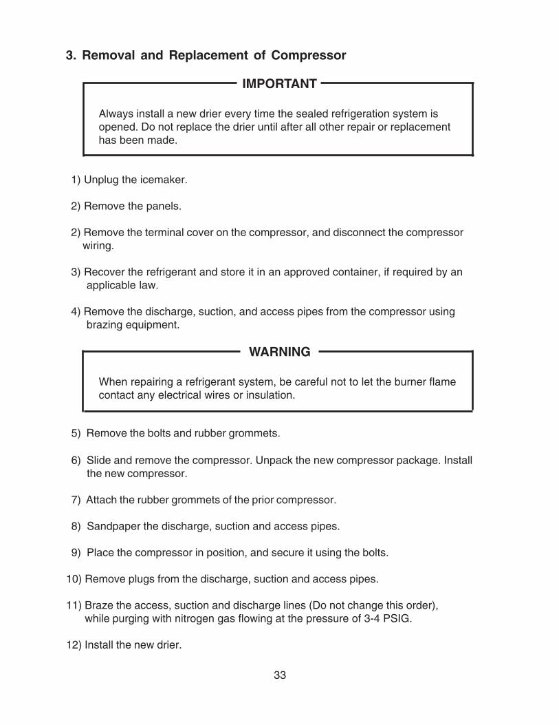
3. Removal and Replacement of Compressor
IMPORTANT
Always install a new drier every time the sealed refrigeration system isopened. Do not replace the drier until after all other repair or replacementhas been made.
1) Unplug the icemaker.
2) Remove the panels.
2) Remove the terminal cover on the compressor, and disconnect the compressor wiring.
3) Recover the refrigerant and store it in an approved container, if required by anapplicable law.
4) Remove the discharge, suction, and access pipes from the compressor usingbrazing equipment.
WARNING
When repairing a refrigerant system, be careful not to let the burner flamecontact any electrical wires or insulation.
5) Remove the bolts and rubber grommets.
6) Slide and remove the compressor. Unpack the new compressor package. Installthe new compressor.
7) Attach the rubber grommets of the prior compressor.
8) Sandpaper the discharge, suction and access pipes.
9) Place the compressor in position, and secure it using the bolts.
10) Remove plugs from the discharge, suction and access pipes.
11) Braze the access, suction and discharge lines (Do not change this order), while purging with nitrogen gas flowing at the pressure of 3-4 PSIG.
12) Install the new drier.
34
13) Check for leaks using nitrogen gas (140 PSIG) and soap bubbles.
14) Evacuate the system, and charge it with refrigerant. See the nameplate for therequired refrigerant charge and type.
15) Connect the terminals to the compressor, and replace the terminal cover in itscorrect position.
16) Replace the panels in their correct position.
17) Plug in the icemaker.
4. Removal and Replacement of Drier
IMPORTANT
Always install a new drier every time the sealed refrigeration system isopened. Do not replace the drier until after all other repair or replacementhas been made.
1) Unplug the icemaker.
2) Remove the panels.
3) Recover the refrigerant and store it in an approved container, if required by anapplicable law.
4) Remove the drier using brazing equipment.
5) Install the new drier with the arrow on the drier in the direction of the refrigerant flow.Use nitrogen gas at the pressure of 3-4 PSIG when brazing the tubings.
6) Check for leaks using nitrogen gas (140 PSIG) and soap bubbles.
7) Evacuate the system, and charge it with refrigerant. See the nameplate for therequired refrigerant charge and type.
8) Replace the panels in their correct position.
9) Plug in the icemaker.

35
1) Unplug the icemaker.
2) Remove the panels.
3) Recover the refrigerant and store it in an approved container, if required by anapplicable law.
4) Remove the expansion valve bulb at the evaporator outlet.
5) Remove the expansion valve cover, and remove the expansion valve usingbrazing equipment.
6) Braze the new expansion valve with nitrogen gas flowing at the pressure of 3-4PSIG.
WARNING
Always protect the valve body by using a damp cloth to prevent the valvefrom overheating. Do not braze with the valve body exceeding 250°F.
5. Removal and Replacement of Expansion Valve
IMPORTANT
Sometimes moisture in the refrigerant circuit exceeds the drier capacityand freezes up at the expansion valve. Always install a new drier everytime the sealed refrigeration system is opened. Do not replace the drieruntil after all other repairs or replacement have been made.
7) Install the new drier.
8) Check for leaks using nitrogen gas (140 PSIG) and soap bubbles.
9) Evacuate the system. Charge it with refrigerant. See the nameplate for the requiredrefrigerant charge and type.
10) Attach the bulb to the suction line. Be sure to secure the bulb using a band and to insulate it.
11) Place the expansion valve cover in position.
12) Replace the panels in their correct position.
13) Plug in the icemaker.
36
.02” Round Stock or Pin Gauge
ExtrudingHead
Auger
6. Removal and Replacement of Evaporator Assembly
1) Drain the water from the evaporator by switching the flush switch to “FLUSH” on thecontrol box.
2) Unplug the icemaker.
3) Remove the panels.
4) Remove the three thumbscrews and take off the spout from the evaporator.
Cutter
5) Loosen the cutter by a wrench and remove it.
6) Remove the cylinder gasket at the top of the evaporator.
Extruding Head
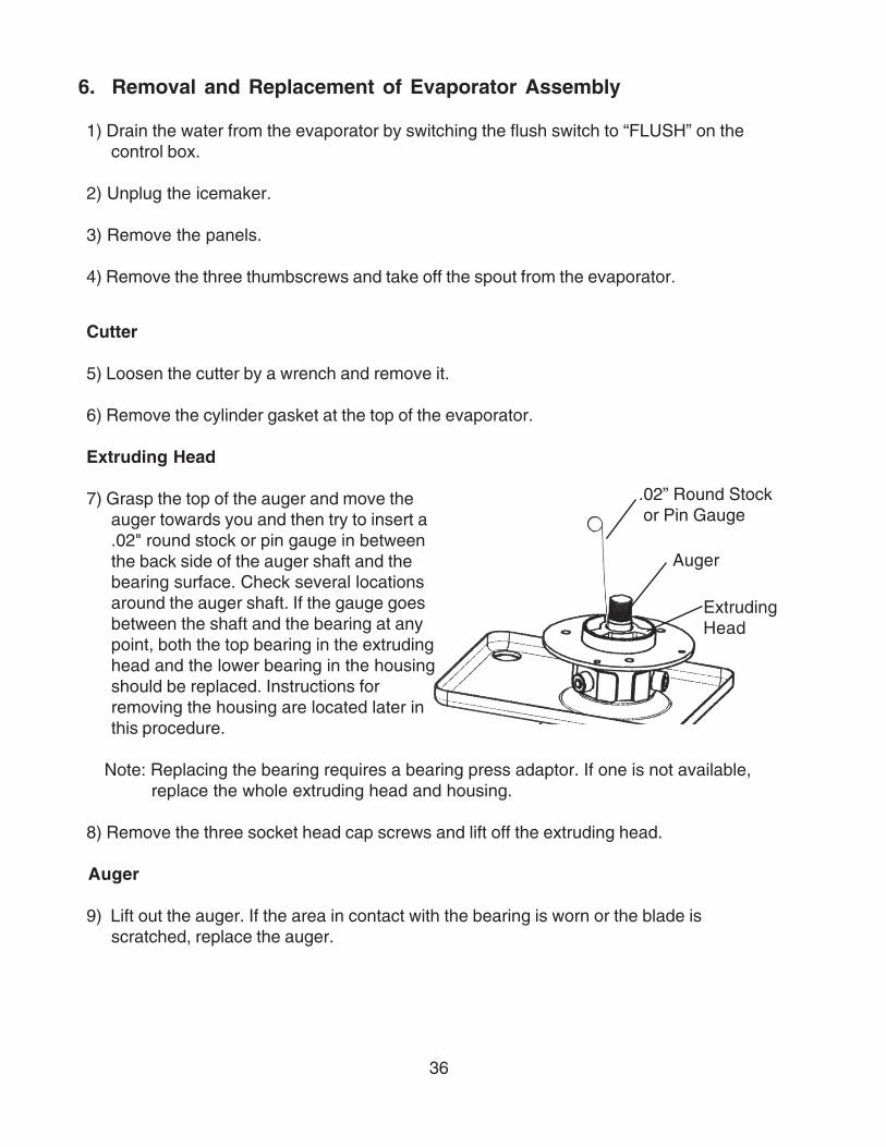
7) Grasp the top of the auger and move theauger towards you and then try to insert a.02" round stock or pin gauge in betweenthe back side of the auger shaft and thebearing surface. Check several locationsaround the auger shaft. If the gauge goesbetween the shaft and the bearing at anypoint, both the top bearing in the extrudinghead and the lower bearing in the housingshould be replaced. Instructions forremoving the housing are located later inthis procedure.
Note: Replacing the bearing requires a bearing press adaptor. If one is not available,replace the whole extruding head and housing.
8) Remove the three socket head cap screws and lift off the extruding head.
Auger
9) Lift out the auger. If the area in contact with the bearing is worn or the blade isscratched, replace the auger.
37
Evaporator
Note: Skip the following steps 10) through 12) when the evaporator does not needreplacement.
10) Recover the refrigerant and store it in an approved container, if required by an applicable law.
IMPORTANT
Always install a new drier every time the sealed refrigeration system isopened. Do not replace the drier until after all other repair or replacementhas been made.
11) Remove the bulb of the expansion valve.
12) Disconnect the brazing-connections of the expansion valve and the copper tube- low side from the evaporator, using brazing equipment.
13) Remove the two truss head machine screws and the bracket securing the evaporator.
14) Disconnect the three hoses from the evaporator.
15) Remove the four socket head cap screws securing the evaporator with the bearing-lower.
16) Lift off the evaporator.
Housing, Lower Bearing and Mechanical Seal
17) The mechanical seal consists of two parts. One moves along with the auger, and theother is fixed on the housing. If the contact surfaces of these two parts are worn orscratched, the mechanical seal may cause water leaks and should be replaced.
18) Remove the O-ring from the housing.
19) Remove the four bolts and the housing from the gear motor. If inspection of thebearing inside the extruding head (earlier in this procedure) indicated that it is out oftolerance, replace both it and the bearing inside the housing.
Note: Replacing the bearing requires a bearing press adaptor. If one is not available,replace the whole extruding head and housing.
38
Gear Motor
20) Remove the coupling-spline on the gear motor shaft.
21) Remove the three bolts securing the gear motor.
22) Assemble the removed parts in the reverse order of the above procedure.
WARNING
Be careful not to scratch the surface of the O-ring, or it may cause water leaks.Handle the mechanical seal with care not to scratch nor to contaminate itscontact surface.
23) When replacing the evaporator:
(a) Braze the new evaporator with nitrogen gas flowing at the pressure of 3-4 PSIG.
(b) Replace the drier.
(c) Check for leaks using nitrogen gas (140 PSIG) and soap bubbles.
(d) Evacuate the system. Charge it with refrigerant. See the nameplate for required refrigerant charge and type.
24) Replace the panels in their correct position.
25) Plug in the icemaker.
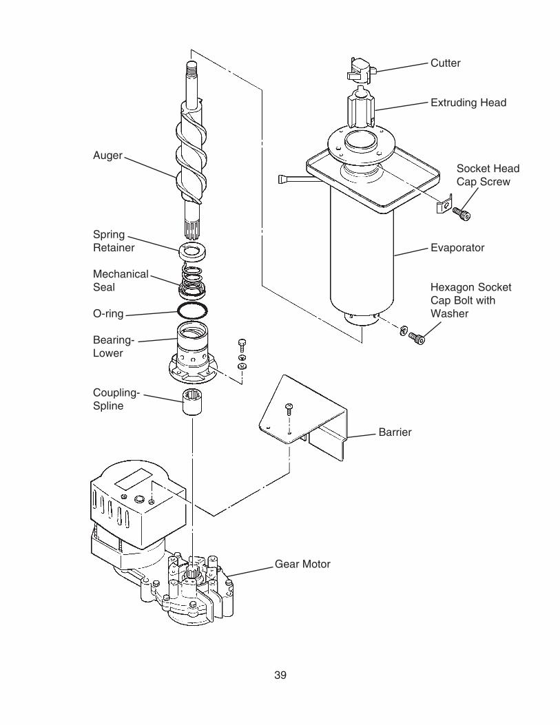
39
Cutter
Extruding Head
AugerSocket HeadCap Screw
SpringRetainer Evaporator
MechanicalSeal Hexagon Socket
Cap Bolt withO-ring Washer
Bearing-Lower
Coupling-Spline
Barrier
Gear Motor

40
7. Removal and Replacement of Fan Motor
1) Unplug the icemaker.
2) Remove the panels.
3) Remove the wire connectors from the fan motor leads.
4) Remove the fan motor bracket and fan motor.
5) Install the new fan motor.
6) Replace the fan motor bracket and the wire connectors.
7) Replace the panels in their correct position
8) Plug in the icemaker.
8. Removal and Replacement of Control Water Valve
1) Unplug the icemaker.
2) Remove the panels.
3) Close the water supply line shut-off valve.
4) Disconnect the terminal from the control water valve.
5) Loosen the fitting nut on the control water valve inlets, and remove the control watervalve. Do not lose the packings inside the fitting nut.
6) Remove the water supply hose from the control water valve.
7) Install the new control water valve.
8) Assemble the removed parts in the reverse order of the above procedure.
9) Open the water supply line shut-off valve.
10) Check for water leaks.
11) Replace the panels in their correct position.
12) Plug in the icemaker.
41
VI. Cleaning and Maintenance
IMPORTANT
Ensure all components, fasteners and thumbscrews are securely in place afterany maintenance or cleaning is done to the equipment.
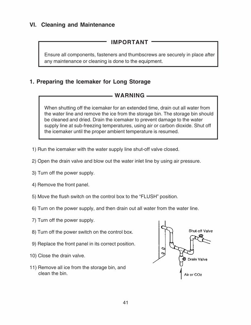
1. Preparing the Icemaker for Long Storage
WARNING
When shutting off the icemaker for an extended time, drain out all water fromthe water line and remove the ice from the storage bin. The storage bin shouldbe cleaned and dried. Drain the icemaker to prevent damage to the watersupply line at sub-freezing temperatures, using air or carbon dioxide. Shut offthe icemaker until the proper ambient temperature is resumed.
1) Run the icemaker with the water supply line shut-off valve closed.
2) Open the drain valve and blow out the water inlet line by using air pressure.
3) Turn off the power supply.
4) Remove the front panel.
5) Move the flush switch on the control box to the “FLUSH” position.
6) Turn on the power supply, and then drain out all water from the water line.
7) Turn off the power supply.
8) Turn off the power switch on the control box.
9) Replace the front panel in its correct position.
10) Close the drain valve.
11) Remove all ice from the storage bin, and clean the bin.
42
2. Cleaning and Sanitizing Instructions
WARNING1. HOSHIZAKI recommends cleaning this unit at least once a year. More
frequent cleaning, however, may be required in some existing waterconditions.
2. To prevent injury to individuals and damage to the icemaker, do not use ammonia type cleaners.3. Always wear liquid-proof gloves to prevent the cleaning and sanitizing
solutions from coming into contact with skin.
[a] Cleaning Solution
Dilute 4.8 fl. oz. (142 ml) of recommended cleaner Hoshizaki “Scale Away” or“LIME-A-WAY” (Economics Laboratory, Inc.) with 0.8 gallons (3 l) of warm water. This is aminimum amount. Make more solution if necessary.
IMPORTANTFor safety and maximum effectiveness, use the solution immediately afterdilution.
[b] Cleaning Procedure
1) Remove the front panel and the top panel, then turn off the power supply.
2) Close the water supply line shut-off valve.
3) Remove all ice from the storage bin.
4) Move the flush switch to the “FLUSH” position.
5) Turn on the power supply and drain out all water from the water line.
6) Turn off the power supply.Note: This unit is designed to start operating when the
reservoir is filled with water.
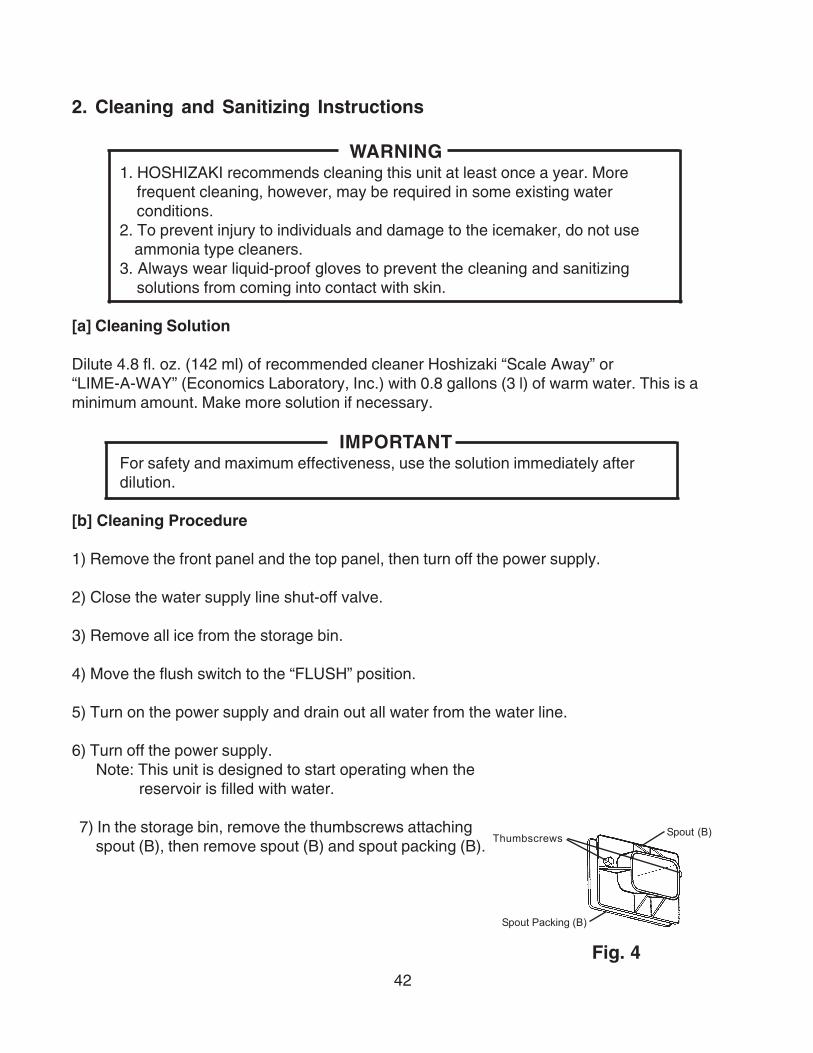
7) In the storage bin, remove the thumbscrews attachingspout (B), then remove spout (B) and spout packing (B).
Thumbscrews Spout (B)
Spout Packing (B)
Fig. 4
43
8) Remove the thumbscrews attaching spout (A) to the evaporator assembly and lift offspout (A) and spout packing (A).
9) Pour the cleaning solution over the extruding head until the evaporator assembly and thereservoir are filled and the solution starts to overflow into the drain pan.
Note: If there is excess scale on the extruding head, fill the evaporator assembly andreservoir as described above, then use a clamp on the reservoir hose between thereservoir and evaporator assembly to block flow. Pour additional cleaning fluidover the extruding head until the evaporator assembly is completely full.
10) Using the thumbscrews, replace spouts (A) and (B) and spout packings (A) and (B) intheir correct positions.
11) Allow the icemaker to sit for about 10 minutes before operation. If you placed a clamp onthe reservoir hose in step 9, remove it before operation.
12) Move the flush switch to the “ICE” position, then turn on the power supply. Replace thetop panel and the front panel in their correct positions. Make ice using the solution untilthe icemaker stops making ice.
13) Remove the front panel.
14) Move the flush switch to the “FLUSH” position to drain the remainder of the solution.
15) After the solution is drained, move the flush switch to the “ICE” position.
16) Replace the front panel in its correct position.
17) Open the water supply line shut-off valve, and supply water to the reservoir.
18) When the gear motor starts, remove the top panel and front panel. Turn off the powersupply.
19) Drain out all water from the water line. See 4) through 6).
[c] Sanitizing Solution
Dilute 2.5 fl. oz. (74 ml or 5 tbs) of IMS-II Sanitizer or a 5.25% sodium hypochlorite solution(chlorine bleach) with 5 gallons (19 l) of warm water.
IMPORTANTFor safety and maximum effectiveness, use the solution immediately afterdilution.
44
[d] Sanitizing Procedure - Initial
1) Close the water supply line shut-off valve.
2) In the storage bin, remove the thumbscrews attaching spout (B), then remove spout (B)and spout packing (B).
3) Remove the thumbscrews attaching spout (A) to the evaporator assembly and lift offspout (A) and spout packing (A), and the cylinder packing.
4) Pour the sanitizing solution over the extruding head until the evaporator assembly andthe reservoir are filled and the solution starts to overflow into the drain pan.
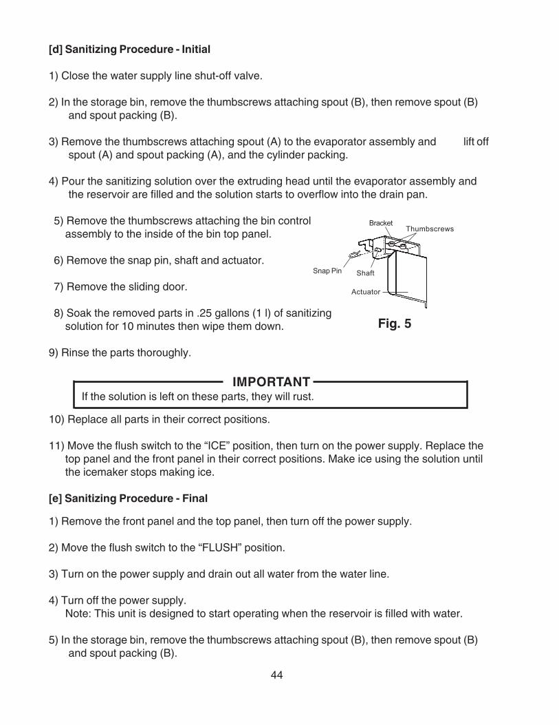
5) Remove the thumbscrews attaching the bin controlassembly to the inside of the bin top panel.
6) Remove the snap pin, shaft and actuator.
7) Remove the sliding door.
8) Soak the removed parts in .25 gallons (1 l) of sanitizingsolution for 10 minutes then wipe them down.
9) Rinse the parts thoroughly.
IMPORTANTIf the solution is left on these parts, they will rust.
10) Replace all parts in their correct positions.
11) Move the flush switch to the “ICE” position, then turn on the power supply. Replace thetop panel and the front panel in their correct positions. Make ice using the solution untilthe icemaker stops making ice.
[e] Sanitizing Procedure - Final
1) Remove the front panel and the top panel, then turn off the power supply.
2) Move the flush switch to the “FLUSH” position.
3) Turn on the power supply and drain out all water from the water line.
4) Turn off the power supply.Note: This unit is designed to start operating when the reservoir is filled with water.
5) In the storage bin, remove the thumbscrews attaching spout (B), then remove spout (B)and spout packing (B).
BracketThumbscrews
ShaftSnap Pin
Actuator
Fig. 5

45
6) Remove the thumbscrews attaching spout (A) to the evaporator assembly and lift off spout(A) and spout packing (A).
7) Pour the sanitizing solution over the extruding head until the evaporator assembly andthe reservoir are filled and the solution starts to overflow into the drain pan.
8) Using the thumbscrews, replace spouts (A) and (B) and spout packings (A) and (B) intheir correct positions.
9) Allow the icemaker to sit for about 10 minutes before operation.
10) Move the flush switch to the “ICE” position, then turn on the power supply. Replace thetop panel and the front panel in their correct positions. Make ice using the solution untilthe icemaker stops making ice.
11) Remove the front panel.
12) Move the flush switch to the “FLUSH” position to drain the remainder of the solution.
13) After the solution is drained, move the flush switch to the “ICE” position.
14) Replace the front panel in its correct position.
15) Open the water supply line shut-off valve and supply water to the reservoir.
16) When the gear motor starts, remove the front panel and turn off the power supply.
17) Drain out all water from the water line. See 2) and 3).
18) Move the flush switch to the “ICE” position and run the icemaker.
19) Turn off the power supply after 30 minutes.
20) Pour warm water into the storage bin to melt all ice, then clean the bin liner with thesolution.
21) Flush out any solution from the storage bin.
22) Turn on the power supply and start the automatic icemaking process.
IMPORTANT1. After cleaning, do not use ice made from the sanitizing solution. Be careful
not to leave any solution in the storage bin.2. Follow carefully any instructions provided with the bottles of cleaning or
sanitizing solution.3. Never run the icemaker when the reservoir is empty.
46
3. Maintenance Instructions
IMPORTANT
1. This icemaker must be maintained individually, referring to the instruction manual and labels provided with the icemaker.
2. To have the optimum performance of this icemaker, the following consumable parts need periodic inspection, maintenance and replacement:
Extruding HeadHousingGear MotorAugerMechanical Seal
These parts should be inspected at least once a year or every 10,000 hours ofoperation. Their service life, however, depends on water quality andenvironment. More frequent inspection and maintenance are recommended.
Consult with your local distributor about inspection and maintenance service.To obtain the name and phone number of your local distributor, call HoshizakiTechnical Support at 1-800-233-1940 in the USA.
1) Stainless Steel Exterior
To prevent corrosion, wipe the exterior occasionally with a clean and soft cloth. Use adamp cloth containing a neutral cleaner to wipe off oil or dirt build up.
2) Storage Bin and Scoop
• Wash your hands before removing ice. Use the plastic scoop provided (bin accessory).
• The storage bin is for ice use only. Do not store anything else in the bin.
• Keep the scoop clean. Clean using a neutral cleaner and rinse thoroughly.
• Clean the bin liner using a neutral cleaner. Rinse thoroughly after cleaning.
47
3) Air Filter
A plastic mesh air filter removes dirt or dust from the air, and keeps the condenserfrom getting clogged. As the filter gets clogged, the icemaker’s performance will bereduced. Check the filter at least twice a month. When clogged, use warm water anda neutral cleaner to wash the filter.
4) Condenser
Check the condenser once a year, and clean if required by using a brush or vacuumcleaner. More frequent cleaning may be required depending on the location of theicemaker.