argus f at001 0514 owserveco 9 ball valves – full bore: ... flowserve corporation has established...
TRANSCRIPT

Experience in Motion
TECHNICAL BULLETINArgus FK 76M FCD ARENTB0001

Argus FCD ARENTB001 05/14
2
Ball Valve FK 76M:
ASME Pressure Classes: DN 2 ½“ – DN 36“ Class 150 - 900
DIN Pressure Classes: DN 65 – DN 900 PN 16 – 160
Design to API 6D /ASME B16.34 / PED 97/23/EC.
Materials: ASME Section II; Pressure / Temperature rating: ASME B16.34; Wall thickness: ASME B16.34; face to face dimension: ASME B16.10, Flange connection ASME B16.5
DIN Design and materials according to PED 97/23/EC.
Split body / 3-piece design, trunnion mounted design, full bore, ends ASME B16.5 or EN or EN 1092-1.
• Fire-safe according to BS 6755 Part 2, ISO 10497 or API 607 6th ed.
• Anti-blow out stem, long life double stem seal system and stem supported in bearings to ensure seals are free form operation loads
• Stem sealing system according to TA-Luft VDI 2440, EPA or EN ISO 15848-1:2006
• Face to face dimensions according to EN 558-1, EN 12980 or ASME B16.10
• Anti-static Design according to DIN EN ISO 17292, chapter 5.2.7
• Ball valve certification for “Exida” for Functional safety according to IEC 61598 SIL 3
Designed to meet API-6D / ASME B16.34 / PED 97/23/EC requirements, the FK76M ball valve represents the highest standards in valve technology. Innovative design features include a superfine finished trunnion mounted ball, low operating torques and an extended service life.
Sizes:
Technical Design Features:
Argus FCD ARENTB001 05/14
3flowserve.com
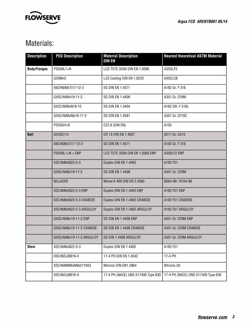
Materials:
Description PPED Description Material Description DIN EN
Nearest theoretical ASTM Material
Body/Flanges P355NL1+N LCS TSTE 355N DIN EN 1.0566 A35OLF2
G20Mn5 LCS Casting DIN EN 1.6220 A352LCB
X6CRNiMoTi17-12-2 SS DIN EN 1.4571 A182 Gr. F 316
GX5CrNiMo19-11-2 SS DIN EN 1.4408 A351 Gr. CF8M
GX2CrNiMoN18 10 SS DIN EN 1.4404 A182 GR. F 316L
GX5CrNiMoNb19-11-2 SS DIN EN 1.4581 A351 Gr. CF10C
P250GH+N C22.8 (DIN EN) A105
Ball GX20Cr14 CR 13 DIN EN 1.4027 A217 Gr. CA15
X6CrNiMoTi17-12-2 SS DIN EN 1.4571 A182 Gr. F 316
P355NL1+N + ENP LCS TSTE 355N DIN EN 1.0566 ENP A350LF2 ENP
X2CrNiMoN22-5-3 Duplex DIN EN 1.4462 A182 F51
GX5CrNiMo19-11-2 SS DIN EN 1.4408 A351 Gr. CF8M
NiCu3OFE Monel K 400 DIN EN 2.4360 B564-99 / B164-98
X2CrNiMoN22-5-3 ENP Duplex DIN EN 1.4462 ENP A182 F51 ENP
X2CrNiMoN22-5-3 CRABIDE Duplex DIN EN 1.4462 CRABIDE A182 F51 CRABIDE
X2CrNiMoN22-5-3 ARGULOY Duplex DIN EN 1.4462 ARGULOY A182 F51 ARGULOY
GX5CrNiMo19-11-2 ENP SS DIN EN 1.4408 ENP A351 Gr. CF8M ENP
GX5CrNiMo19-11-2 CRABIDE SS DIN EN 1.4408 CRABIDE A351 Gr. CF8M CRABIDE
GX5CrNiMo19-11-2 ARGULOY SS DIN 1.4408 ARGULOY A351 Gr. CF8M ARGULOY
Stem X2CrNiMoN22-5-3 Duplex DIN EN 1.4462 A182 F51
X5CrNiCuNB16-4 17-4 PH DIN EN 1.4542 17-4 PH
X2CrNiMNMoNNb211653 Nitronic DIN EN1.3964 Nitronic 50
X5CrNiCuNB16-4 17-4 PH (NACE) UNS S17400 Type 630 17-4 PH (NACE) UNS S17400 Type 630

Argus FCD ARENTB001 05/14
4
Materials (...):
Valve Body Design: (Standard, alternative design on request)
Stem Seals PTFE; FPM, Graphite
Ball seats PTFE/ss, POM/ss; LYTON/ss spring loaded, Cavity Relief
X2CrNiMon22-5-3 ENP Duplex DIN EN 1.4462 ENP A182 F51 ENP
X2CrNiMoN22-5-3 CRABIDE Duplex DIN EN 1.4462 CRABIDE A182 F51 CRABIDE
X2CrNiMoN22-5-3 ARGULOY Duplex DIN EN 1.4462 ARGULOY A182 F51 ARGULOY
Body Seals PTFE; FPM, Graphite
Screws A193 Gr. B8MN Cl.2; A193 GR. 88mN2 Cl.2B; A4-70; A198 Gr. B7; A198 Gr. B7M; A320 Gr.L7; A320Gr. L/M; 1.4980
Nuts A192 Gr.8M; A4-70; A194 Gr.2HM; A194 Gr. 7M;A194 Gr. 4; 1.4980
Note: Speccial materials and alloy on requesty; e.g. inconel, Alloy 20, Super Duplex, Monel, Hastelloy or seawater resistant bronze
mm ln
900 36
850 34
800 32
750 30
700 280 Design: 3-pc. Body650 65
600 24
500 20
450 18
400 16
350 14
300 12
250 10 Design:2-pc. Split body200 8
150 6
100 4
80 3
ANSI CLASS: 150 300 400 600 900
DIN PN: 10/16 40 63 100 160

Argus FCD ARENTB001 05/14
5flowserve.com
Soft Seat Materials:PTFE: Polytetrafluorethene; very high chemical resistance, minimized coefficient of friction
POM: Polyoxymethylene; high solidity, hardness and rigidity values by high abrasion resistance and low coefficient of friction
LYTON (PEEK): Polyetheretherketone; high chemical resistance, higher temperature rating; high solidity in combination with high abrasion resistance

Argus FCD ARENTB001 05/14
6
Ball Seat Systems:
PTFE (TA-Luft)/Graphite (Fire-safe)
PTFE (ISO 15848)/Graphite (Fire-safe)
Graphite (TA-luft) High temperature
Graphite (ISO 15848)High temperature
PTFE / SS / Duplex POM / SS / Duplex Lyton (PEEK) / POM / SS / Duplex Chambered version
POM / SS /. Duplex – Secondary - sealing system
Metal seated O-ring Version Metal seated Graphite version DN 80-150
Metal seated Graphite version from DN 200
Optional: Double Piston, cavity relief
on request
Stem Sealing Systems:
Argus FCD ARENTB001 05/14
7flowserve.com
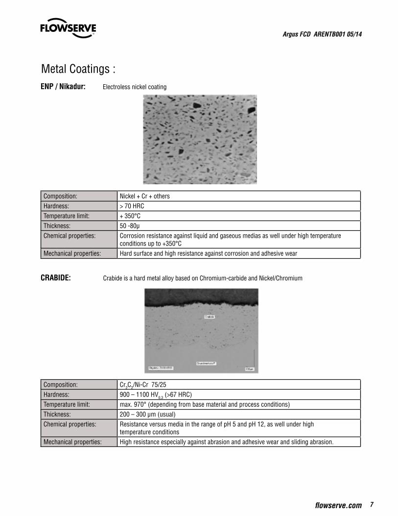
Metal Coatings : ENP / Nikadur: Electroless nickel coating
CRABIDE: Crabide is a hard metal alloy based on Chromium-carbide and Nickel/Chromium
Composition: Nickel + Cr + othersHardness: > 70 HRCTemperature limit: + 350°CThickness: 50 -80µChemical properties: Corrosion resistance against liquid and gaseous medias as well under high temperature
conditions up to +350°CMechanical properties: Hard surface and high resistance against corrosion and adhesive wear
Composition: Cr2C2/Ni-Cr 75/25Hardness: 900 – 1100 HV0,3 (>67 HRC)Temperature limit: max. 970° (depending from base material and process conditions) Thickness: 200 – 300 µm (usual)Chemical properties: Resistance versus media in the range of pH 5 and pH 12, as well under high
temperature conditionsMechanical properties: High resistance especially against abrasion and adhesive wear and sliding abrasion.
Argus FCD ARENTB001 05/14
8
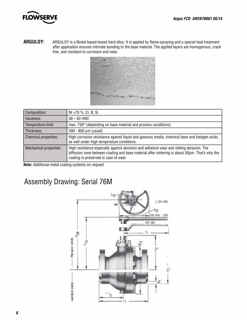
Assembly Drawing: Serial 76M
ARGULOY: ARGULOY is a Nickel based-based hard alloy. It is applied by flame-spraying and a special heat treatment after application ensures intimate bonding to the base material. The applied layers are homogenous, crack free, and resistant to corrosion and wear.
Composition: Ni >70 %, Cr, B, SiHardness: 58 – 62 HRCTemperature limit: max. 750° (depending on base material and process conditions)Thickness: 500 - 800 µm (usual)Chemical properties: High corrosion resistance against liquid and gaseous media; chemical base and halogen acids,
as well under high temperature conditions. Mechanical properties: High resistance especially against abrasion and adhesive wear and sliding abrasion. The
diffusion zone between coating and base material after sintering is about 50µm. That’s why the coating is preserved in case of wear.
Note: Additional metal coating systems on request
Argus FCD ARENTB001 05/14
9flowserve.com
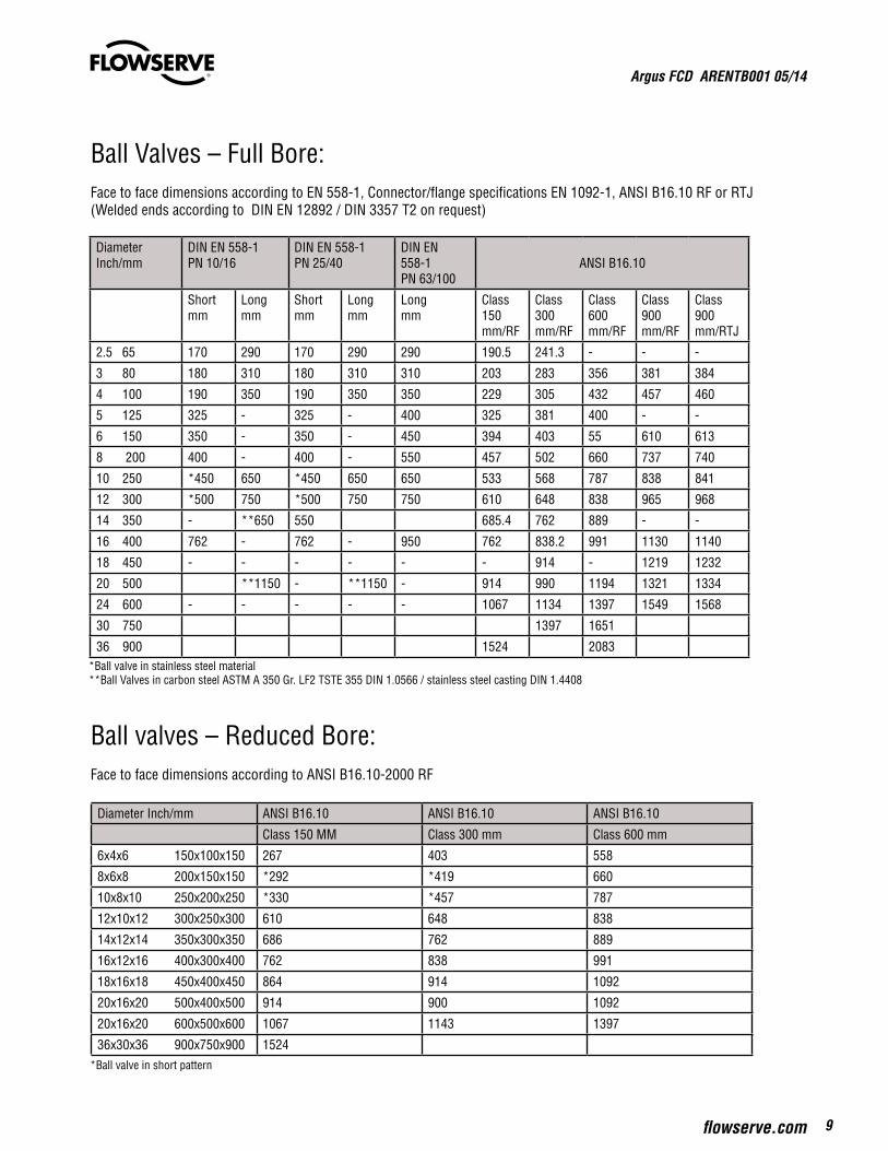
Ball Valves – Full Bore: Face to face dimensions according to EN 558-1, Connector/flange specifications EN 1092-1, ANSI B16.10 RF or RTJ(Welded ends according to DIN EN 12892 / DIN 3357 T2 on request)
Ball valves – Reduced Bore:Face to face dimensions according to ANSI B16.10-2000 RF
DiameterInch/mm
DIN EN 558-1PN 10/16
DIN EN 558-1PN 25/40
DIN EN558-1PN 63/100
ANSI B16.10
Shortmm
Longmm
Shortmm
Longmm
Longmm
Class 150mm/RF
Class 300mm/RF
Class 600mm/RF
Class 900mm/RF
Class 900mm/RTJ
2.5 65 170 290 170 290 290 190.5 241.3 - - -
3 80 180 310 180 310 310 203 283 356 381 384
4 100 190 350 190 350 350 229 305 432 457 460
5 125 325 - 325 - 400 325 381 400 - -
6 150 350 - 350 - 450 394 403 55 610 613
8 200 400 - 400 - 550 457 502 660 737 740
10 250 *450 650 *450 650 650 533 568 787 838 841
12 300 *500 750 *500 750 750 610 648 838 965 968
14 350 - **650 550 685.4 762 889 - -
16 400 762 - 762 - 950 762 838.2 991 1130 1140
18 450 - - - - - - 914 - 1219 1232
20 500 **1150 - **1150 - 914 990 1194 1321 1334
24 600 - - - - - 1067 1134 1397 1549 1568
30 750 1397 1651
36 900 1524 2083*Ball valve in stainless steel material **Ball Valves in carbon steel ASTM A 350 Gr. LF2 TSTE 355 DIN 1.0566 / stainless steel casting DIN 1.4408
Diameter Inch/mm ANSI B16.10 ANSI B16.10 ANSI B16.10
Class 150 MM Class 300 mm Class 600 mm
6x4x6 150x100x150 267 403 558
8x6x8 200x150x150 *292 *419 660
10x8x10 250x200x250 *330 *457 787
12x10x12 300x250x300 610 648 838
14x12x14 350x300x350 686 762 889
16x12x16 400x300x400 762 838 991
18x16x18 450x400x450 864 914 1092
20x16x20 500x400x500 914 900 1092
20x16x20 600x500x600 1067 1143 1397
36x30x36 900x750x900 1524*Ball valve in short pattern

Argus FCD ARENTB001 05/14
10
Serial Classification: FK 76M DN 80, 100, 150, 200, 250, 300FK 76 (M) DN 65, 125, 350, 400FK 76M DN 450, 500, 600, 750, 900
Design Options:
Heating jackets, double sided Wearing bushes (abrasive wear)
Seat pocket design: Solids / Fines / Slurry (ball seat area)
Argus FCD ARENTB001 05/14
11flowserve.com
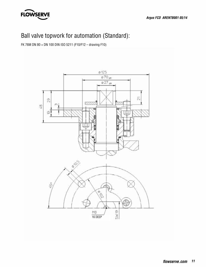
Ball valve topwork for automation (Standard):FK 76M DN 80 + DN 100 DIN ISO 5211 (F10/F12 – drawing F10)
16 DEEP

Argus FCD ARENTB001 05/14
12
FK 76M DN 80 + DN 100 DIN ISO “419”
Center of valve

Argus FCD ARENTB001 05/14
13flowserve.com
FK 76M DN 80 + DN 100 DIN ISO “419” High temperature design:

Argus FCD ARENTB001 05/14
14
FK 76M DN 150 + DN 200 DIN ISO “419”
Center of valve

Argus FCD ARENTB001 05/14
15flowserve.com
FK 76M DN 150 + DN 200 DIN ISO “419”High temperature design:
25 DEEP

Argus FCD ARENTB001 05/14
16
FK 76M DN 250 + DN 300 DIN ISO “419”
DEEP
DEEP

Argus FCD ARENTB001 05/14
17flowserve.com
FK 76M DN 250-900 (3-pc design) Topwork ; “519”
FK 76M DN 250 -900 (3-pc.- Design) High temperature design
topview
Dimension on request
topview
To find your local Flowserve representative or for more information about Flowserve Corporation, visit www.flowserve.com or call USA 1 800 225 6989
FCD ARENTB0001 Printed in France 05/14
Flowserve Corporation has established industry leadership in the design and manufacture of its products. When properly selected, this Flowserve product is designed to perform its intended function safely during its useful life. However, the purchaser or user of Flowserve products should be aware that Flowserve products might be used in numerous applications under a wide variety of industrial service conditions. Although Flowserve can (and often does) provide general guidelines, it cannot provide specific data and warnings for all possible applications. The purchaser/user must therefore assume the ultimate responsibility for the proper sizing and selection, installation, operation, and maintenance of Flowserve products. The purchaser/user should read and understand the Installation Operation Maintenance (IOM) instructions included with the product, and train its employees and contractors in the safe use of Flowserve products in connection with the specific application.
While the information and specifications contained in this literature are believed to be accurate, they are supplied for informative purposes only and should not be considered certified or as a guarantee of satisfactory results by reliance thereon. Nothing contained herein is to be construed as a warranty or guarantee, express or implied, regarding any matter with respect to this product. Because Flowserve is continually improving and upgrading its product design, the specifications, dimensions and information contained herein are subject to change without notice. Should any question arise concerning these provisions, the purchaser/user should contact Flowserve Corporation at any one of its worldwide operations or offices.
© 2014 Flowserve Corporation, Irving, Texas, USA. Flowserve is a registered trademark of Flowserve Corporation.
Flowserve Flow Control GmbHRudolf-Plank-Straße 2D-76275 EttlingenGermany,T: +49 7243 103-0F: +49 7243 103-222