f-cdm-poa-dd programme design document form for...
TRANSCRIPT
F-CDM-PoA-DD
Version 03.0 Page 1 of 92
Programme design document form for CDM programmes of activities
(Version 03.0)
PART I. Programme of activities (PoA)
SECTION A. General description of PoA A.1. Title of the PoA >> (a) RE2Grid PoA (b) Version number 5 (c) 21/12/2012
A.2. Purpose and general description of the PoA >> The RE2Grid PoA aims to promote the utilization of renewable energy (RE) resources by supporting the development of a number of greenfield renewable energy projects (wind, run-of-river hydroelectric, geothermal, solar PV, wave and tidal energy) that feed electric power into a grid. The Coordinating and Managing Entity (CME) is Carbonergy Business Consultancy Services (CBCS). CBCS and Cornland International (a project participant) have created a platform that enables developers of such projects to overcome financial and other barriers to developing and implementing their projects, by harnessing the financial support made available through the sale of carbon credits. This PoA platform will initially be utilized in the Republic of the Philippines. Expansion to additional host countries is anticipated. The PoA will contribute to reducing developing countries’ heavy and increasing dependence on fossil fuels for electricity generation while helping to mitigate global climate change. (a) Policy/measure or stated goal that the PoA seeks to promote The development objective of the PoA is to facilitate the implementation of grid-connected renewable energy projects. There are no legal requirements to implement RE projects in the Philippines. However, there are a number of national legislative instruments that have been put in place to support the development of the sector in general. Our intent is to support the goals set in two of those instruments, namely the National Renewable Energy Program (NREP) 1 and the National Climate Change Action Plan (NCCAP) 2011-2028.2 The NCCAP calls for “enhancement in the development of sustainable and renewable energy”. NREP has set goals to add the following PoA-eligible RE technology capacity by 2030:
• 5,394MW hydropower (ca. 90% to come from large hydro, i.e. over 10MW facilities3);• 2,345MW wind power; • 1,495MW geothermal
1 http://www.doe.gov.ph/nrep/index.asp?opt=nrepbook, page 23, table 3 2 National Climate Change Action Plan 2011-2028, Section 6, pages 23-26. Provided to DOE for validation. 3 Large hydro is classified by the Philippine Department of Energy (PDOE) as more than 10MW while mini-hydro is
1.01-10MW
F-CDM-PoA-DD
Version 03.0 Page 2 of 92
• 284MW solar power; and • 70.5MW ocean energy.
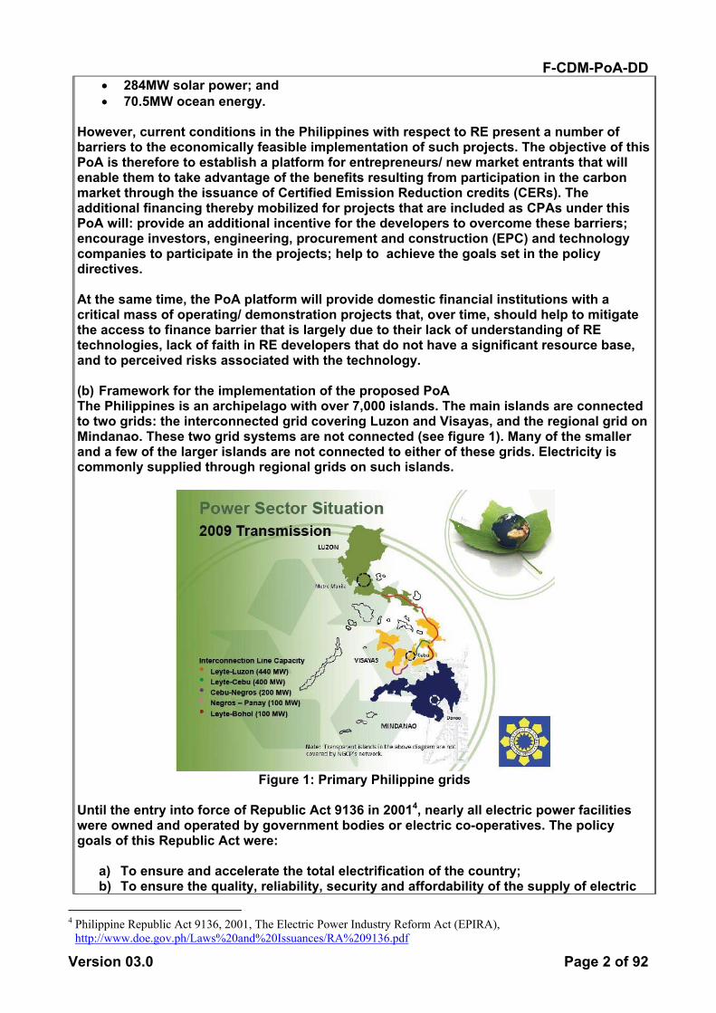
However, current conditions in the Philippines with respect to RE present a number of barriers to the economically feasible implementation of such projects. The objective of this PoA is therefore to establish a platform for entrepreneurs/ new market entrants that will enable them to take advantage of the benefits resulting from participation in the carbon market through the issuance of Certified Emission Reduction credits (CERs). The additional financing thereby mobilized for projects that are included as CPAs under this PoA will: provide an additional incentive for the developers to overcome these barriers; encourage investors, engineering, procurement and construction (EPC) and technology companies to participate in the projects; help to achieve the goals set in the policy directives. At the same time, the PoA platform will provide domestic financial institutions with a critical mass of operating/ demonstration projects that, over time, should help to mitigate the access to finance barrier that is largely due to their lack of understanding of RE technologies, lack of faith in RE developers that do not have a significant resource base, and to perceived risks associated with the technology. (b) Framework for the implementation of the proposed PoA The Philippines is an archipelago with over 7,000 islands. The main islands are connected to two grids: the interconnected grid covering Luzon and Visayas, and the regional grid on Mindanao. These two grid systems are not connected (see figure 1). Many of the smaller and a few of the larger islands are not connected to either of these grids. Electricity is commonly supplied through regional grids on such islands.
Figure 1: Primary Philippine grids
Until the entry into force of Republic Act 9136 in 20014, nearly all electric power facilities were owned and operated by government bodies or electric co-operatives. The policy goals of this Republic Act were:
a) To ensure and accelerate the total electrification of the country; b) To ensure the quality, reliability, security and affordability of the supply of electric
4 Philippine Republic Act 9136, 2001, The Electric Power Industry Reform Act (EPIRA),
http://www.doe.gov.ph/Laws%20and%20Issuances/RA%209136.pdf

F-CDM-PoA-DD
Version 03.0 Page 3 of 92
power; c) To ensure transparent and reasonable prices of electricity in a regime of free and
fair competition and full public accountability to achieve greater operational and economic efficiency and enhance the competitiveness of Philippine products in the global market;
d) To enhance the inflow of private capital and broaden the ownership base of the power generation, transmission and distribution sectors in order to minimize the financial risk exposure of the national government;
e) To ensure fair and non-discriminatory treatment of public and private sector entities in the process of restructuring the electric power industry;
f) To protect the public interest as it is affected by the rates and services of electric utilities and other providers of electric power;
g) To assure socially and environmentally compatible energy sources and infrastructure;
h) To promote the utilization of indigenous and new and renewable energy resources in power generation in order to reduce dependence on imported energy;
i) To provide for an orderly and transparent privatization of the assets and liabilities of the National Power Corporation (NPC).
j) To establish a strong and purely independent regulatory body and system to ensure consumer protection and enhance the competitive operation of the electricity market; and
k) To encourage the efficient use of energy and other modalities of demand side management.
Since then a large portion of the mostly large-scale government-owned power facilities, several of which employ renewable energy technologies (largely hydropower and geothermal), have been privatized by the Power Sector Assets and Liabilities Management Corporation (PSALM). More recently, Republic Act 95135 ‘harmonized’ a number of hitherto disparate regulations for different renewable energy technologies. This Act declared that the Philippines aimed to:
• Accelerate exploration and development of renewable energy resources; • Adopt sustainable energy development strategies; • Reduce dependence on imported fossil fuels; • Reduce exposure to fluctuations in prices of fossil fuels; • Increase RE utilization; • Provide fiscal and non-fiscal incentives; and • Reduce harmful emissions.
In 2011, net electricity generation in the Luzon-Visayas grid was 76.32% fossil fuel (coal, oil-based and natural gas) and 23.68% RE (geothermal, hydro, wind and biomass). The Mindanao grid roughly reverses these figures with 66.23% RE (mostly large hydro and geothermal with a small solar installation) and 33.77% fossil fuel (coal and oil-based)6. Regional grids are currently most commonly supplied with diesel gensets. The Mindoro regional grid is no exception to this rule, with 95.5 percent of all power generation over the past five years supplied with diesel gensets, and the remaining 4.5 percent supplied with small-scale hydropower.7
5 Philippine Republic Act 9513, 2008, The Renewable Energy Act of 2008,
http://www.doe.gov.ph/Laws%20and%20Issuances/RA%209513.pdf 6 Provided to the DOE for validation 7 Provided to the DOE for validation

F-CDM-PoA-DD
Version 03.0 Page 4 of 92
Due to increasing demand from a growing population and economy, there is an impending shortage of power in all regions of the Philippines and several coal-fired power plants are being built or are in advanced stages of planning (610MW came on-grid in 2010-2011 in the Visayas)8. The Philippine government through the Department of Energy (PDOE) has set a target to double RE capacity between 2010 and 20309; RE plants have averaged close to 27% of total capacity for the last three years in the Luzon-Visayas grid, which accounts for close to 85% of on-grid power generated in the country10. The majority of RE developers in the Philippines are confronted with significant barriers to reaching financial closure of their projects that, despite the expectations raised by the Renewable Energy Act, continue to be major contributing factors that are delaying the emergence of a vibrant RE sector in the country. While power generation from renewable resources is incentivized under the Renewable Energy Act, the expectations it raised had not been realized at the time of preparing this document (42 months after the Act’s passage) and submitting it for global stakeholder review. Therefore, all proposed wind, geothermal, large-scale hydropower, solar and ocean power facilities remained in limbo. This was partly due to the lengthy processes required to complete the details of the Act’s Implementing Rules and Regulations (IRR) such as the Renewable Portfolio Standard (RPS) and the Feed-in-Tariffs (FiTs). It was expected at that time that several more months would be required just to finalize the FiTs11. There are several other RE Act instruments that also need to be completed. In addition, legislators are now considering changes to the way in which some initial permits will be allocated,12 so additional delays can be expected in finalizing all rules and regulations required to fully operationalize the Act. Also, despite lengthy discussions with RE project developers preceding the National Renewable Energy Board’s (NREB) petition to the Energy Regulatory Committee (ERC), the FiT proposals submitted were generally deemed by developers to be insufficient to provide their hoped-for levels of return13,14. At the same time, the public and non-governmental organizations (NGOs) were voicing their opposition to the increased power bills that consumers would have to bear from the pass through charges under the FiT Allowance (FiT-All)15 and one government agency threatened to remove mandated tax holidays once FiTs were in place.16 Consequently, there was increasing doubt among RE developers that the Act would ever deliver the returns they were expecting. Therefore, additional incentives, such as financial flows that can be derived from the CDM, are again receiving attention by developers and investors/ financiers alike. RE project developers that have already been or soon will be awarded pre-development contracts by PDOE are taking a risk by investing in the initial studies and activities to flesh
8 Provided to the DOE for validation 9 Op. cit. Ref 1 10 Op. cit Ref 8 11 FiTs for wind, run-of-river hydropower, solar PV and biomass were finally approved by Energy Regulatory
Committee (ERC) July 27th 2012, while the FiT for ocean technologies was deferred pending further review 12 http://www.mb.com.ph/articles/352919/congress-lays-down-policy-direction-for-auction-of-re-installations 13 Provided to the DOE for validation 14 Provided to the DOE for validation 15 Article provided to the DOE for validation16 http://www.mb.com.ph/articles/338762/domingo-rejects-ith-to-re17
http://www.erc.gov.ph/pdf/NREB(Petition-FIT).pdf 16 http://www.mb.com.ph/articles/338762/domingo-rejects-ith-to-re17 http://www.erc.gov.ph/pdf/NREB(Petition-
FIT).pdf

F-CDM-PoA-DD
Version 03.0 Page 5 of 92
out their projects as they may not be able to complete all requirements in time to be awarded FiTs anyway due to the proposed first phase RE installation target of 830MW17 that includes the following caps for PoA-eligible technologies:
• 250MW for run-of-river hydro; • 220MW for wind power; • 100 for solar PV; and • 10MW for ocean (thermal).
However, Philippine legislators are now considering introducing a bidding system18 for some projects that will be accepted under these installation caps and the Department of Energy has been asked to review the draft policy directive. This recent development and the proposed caps create a non-transparent environment and uncertainty among investors on whether their project will be awarded a FiT. The PDOE has received many more applications for pre-development contracts (a pre-condition for being awarded a FiT) than can possibly be accepted under the caps for all but hydro. This, together with the pending legislative change, means that many developers will have to wait to develop their projects if they are dependent on a FiT or take a risk by investing in the required pre-development activities. In either case, the developers could offset these risks by applying for CERs for their projects. There are also many projects under development that are located in regional grid areas that are not eligible for FiTs where the decision to invest will have to rely even more on additional revenue streams such as from CERs to become more interesting to the investors.
The proposed PoA is a voluntary action taken by the CME. Individual RE project developers mostly in the private sector (CPA owners), will plan, design, construct and operate their projects that will be included in the PoA as single CPAs. This PoA addresses the challenges to increased implementation of renewable energy technologies and intends to promote their contribution to electricity supply in the national and regional grids of CPA countries. Among the overall macro development benefits of the PoA are:
• Reduced use of fossil fuels that have various negative effects on the local and global environment;
• Improved balance of payments/ foreign currency reserves (fossil fuel prices are increasing and the domestic currencies are becoming stronger against the US$);
• Utilization of nationally-available, renewable, zero-carbon and zero-cost feedstock; • Increased share of RE in the energy mix; • Promotion of rural electrification objectives and improved infrastructure for rural
development. In addition, at the micro level, CPAs will:
• Contract domestic companies and workers for planning, engineering design, construction and operation of facilities;
• Contribute new financial resources to host communities in the form of taxes (e.g. real property, local business and special privilege taxes);
• Contribute to improving the power supply to the communities served by the local electric cooperatives;
17 http://www.erc.gov.ph/pdf/NREB(Petition-FIT).pdf 18 Op cit. Ref 12
F-CDM-PoA-DD
Version 03.0 Page 6 of 92
• Improve the local road network by building/ improving all-weather roads to facilitate access to plant sites;
• Provide livelihoods, jobs & income o During construction (office staff & personnel, engineers, technicians, drivers,
labourers, guards, medical staff) o In the completed plant (plant manager, plant operators, security guards,
bookkeeper/secretary, maintenance staff) and related service jobs (repair & maintenance, professional services, health support) during operation
o Through enabling new & alternative productive activities; • Provide ancillary benefits (technical visitors, overnight stays, servicing meetings/
conferences) to the local community.
A.3. CMEs and participants of PoA >> (a) Coordinating/ Managing Entity: Carbonergy Business Consultancy Services
(b) Project participants to the PoA: Carbonergy Business Consultancy Services, Cornland
International AB and Bulalacao Wind Power Corp.
A.4. Party(ies)
Name of Party involved (host) indicates a host
Party
Private and/or public entity(ies) project participants (as
applicable)
Indicate if the Party involved wishes to be considered as project participant (Yes/No)
Republic of the Philippines (host)
Private entity a): Carbonergy Business Consultancy Services Private entity b): Bulalacao Wind Power Corp.
No
Sweden Private entity a): Cornland International AB
No
A.5. Physical/ Geographical boundary of the PoA >> The geographical boundary of the PoA is defined as the geographical area within which all the implemented CPAs included in the PoA will be physically installed. All CPAs under this PoA will be within the borders of the PoA Host Parties (Philippines). If the boundary of the PoA is amended post-registration to expand the geographic coverage or to include one or more additional host Parties, the CME shall update the eligibility criteria to reflect the consequent changes. A new version of the PoA DD (e.g. version 1.2) containing updated eligibility criteria validated by a DOE shall be submitted to the Board for approval.
(a) Once changes have been approved by the Board, the inclusion of all new CPAs shall be based on the updated eligibility criteria; (b) CPAs that were included before the boundary of the PoA was amended shall apply the revised eligibility criteria only at the time of the renewal of the crediting period.
F-CDM-PoA-DD
Version 03.0 Page 7 of 92
A.6. Technologies/measures >> In accordance with ACM0002 version 13, “The PoA may consist of one or several types of CPAs. CPAs are regarded to be of the same type if they are similar with regard to the demonstration of additionality, emission reduction calculations and monitoring.” Further, “The CME shall describe transparently and justify in the CDM-PoA-DD which CPAs are regarded to be of the same type. CPAs shall not be regarded to be of the same type if one of the following conditions is different:”
a. The project activity with regard to any of the following aspects: (i) Renewable power generation technology;
(ii) Project activity type:
b. The legal and regulatory framework; This PoA contains six CPA-types, comprising the following power-generation technologies:
1. CPA type 1: wind 2. CPA type 2: run-of-river hydro 3. CPA type 3: solar PV 4. CPA type 4: wave 5. CPA type 5: tidal 6. CPA type 6: geothermal.
The first five types (wind, run-of-river hydro, solar PV, wave and tidal project activities) are all renewable power generation technologies, are the same project activity type (greenfield), and are implemented under the same legal and regulatory framework. They are also similar with regard to the demonstration of additionality, emission reduction calculations and monitoring. The sixth type, CPA-type 6, is defined for geothermal project activities. Geothermal is also a renewable energy technology, must be greenfield under this PoA, and is similar with regard to the demonstration of additionality. In the Philippines, geothermal is also implemented under the same regulatory framework as the other CPA-type technologies. Geothermal CPAs differ compared to CPA-types 1-5 with respect to emission-reduction calculations and monitoring. The detailed technical characteristics of the individual CPAs will differ. However, the following general conditions will apply for typical CPAs. A typical CPA will consist of the construction of a greenfield renewable energy project utilizing either wind, run-of-river hydroelectric19, solar PV, wave, tidal or geothermal power technology (PoA-eligible projects) utilizing new equipment. The CPA will feed electric power into a grid, avoiding grid-based greenhouse-gas emissions. Typical design capacity ranges for each technology in the Philippines are:
• Wind 2-120 MW • Solar PV 0.5-50 MW
19 This PoA is not applicable to hydro power plants that result in the creation of a new accumulation reservoir or
increases the volume of an existing reservoir where the resulting power density is less than 4 W/m2. See Eligibility criteria for inclusion of a CPA in the PoA, Part I Section B.2.

F-CDM-PoA-DD
Version 03.0 Page 8 of 92
• Run-of-river hydropower 0.2-45MW • Geothermal 20-120MW • Tidal 1-10MW • Wave (not available)
These ranges have been derived from PDOE published sources on renewable energy development in the Philippines20,21. The construction of such RE projects usually includes the following common components:
• Connection lines to the feed-in point of the grid; • Transformer station; • Electricity meters.
The specific technologies will, depending on the solution chosen, usually include the following components:
• CPA type 1: Wind: turbines and towers/ masts; • CPA type 2: Run-of-river hydro: diversion facilities (canal or penstock for run-of-
river), with turbines and generator(s); • CPA type 3: Solar PV: photovoltaic panels (direct to electricity); • CPA type 4: Wave: wave-power systems vary significantly by design, but can
include point absorbers or buoys, hydraulic or mechanical pumps, offshore reservoirs, turbines or generators;
• CPA type 5: Tidal: tidal-power systems vary significantly by design, but can include tidal stream generators or tidal barrage structures and turbines;
• CPA type 6: Geothermal: steam turbines, generators, steam/water separators, heat exchangers.
A.7 Public funding of PoA >> The PoA does not receive public funding.
SECTION B. Demonstration of additionality and development of eligibility criteria
B.1. Demonstration of additionality for PoA >>
In accordance with the Standard for Demonstration of Additionality, Development of Eligibility Criteria and Application of Multiple Methodologies for Programme of Activities (Version 02.1), paragraph 7, “Additionality shall be demonstrated by establishing that in the absence of CDM, none of the implemented CPAs would occur.”
Framework for demonstrating the additionality of a CPA
The additionality framework for this PoA requires the following procedures to be followed for all project activities in each CPA seeking inclusion (see also figure 2):
20 http://www.doe.gov.ph/RE%20Regis&accred/Awarded%20Contracts/Hydro/Hydro.pdf 21 Op. Cit. Ref 1

F-CDM-PoA-DD
Version 03.0 Page 9 of 92
Procedure 0: Determine the CPA type for the CPA seeking inclusion.
For CPA types 1, 2, 3 and 6 proceed to Procedure 1. CPA types 4 and 5 are for wave- and tidal-power systems, respectively. Wave- and tidal-power system are nascent technologies with few applications globally and no applications to date in the Philippines. Credible alternative to the project activity: Delivering electricity to the grid by the operation of grid-connected power plants and by the addition of new generation sources, as reflected in the combined margin (CM) calculations described in the “Tool to calculate the emission factor for an electricity system” is clearly a realistic and credible alternative scenario(s) to project activities applying tidal- and wave-power technologies. Consistency with mandatory laws and regulations: There are no laws or regulations requiring greenfield grid-connected renewable power plant/unit(s). However, as mentioned in section A.2 above, there are national legislative instruments that encourage the development of the sector in general, e.g. the Renewable Energy Act, the National Renewable Energy Program, and the National Climate Change Action Plan.Therefore, project activities applying tidal- and wave-power technologies are consistent with Philippine mandatory laws and regulations. Barrier analysis: These are unfamiliar and untested technologies for the ASEAN region. As such, they clearly face significant technological barriers that prevent their implementation in the Philippines. (a) These technologies are not manufactured in the ASEAN region available in the relevant
region and must, therefore, be imported; (b) Skilled and/or properly trained labour to operate and maintain the technology is not
available in the Philippines, which leads to an unacceptably high risk of equipment disrepair and malfunctioning or other underperformance;
(c) The Philippines lacks necessary infrastructure for implementation and logistics for maintenance of these technologies. For example, because key electro-mechanical components must be imported, replacement parts must be ordered from abroad and significant repair delays can occur;
(d) Risk of technological failure: the process/technology failure risk in the local circumstances is significantly greater than for other technologies that provide services or outputs comparable to those applying tidal and wave technologies. As these are nascent technologies with very few applications internationally, and no technological expertise or experience adapting them to the specific conditions of the Philippines, there is a higher risk of technology failure for these power options as compared to fossil fuel energy generation technologies that have a well-established supportive infrastructure22;
(e) The levelized cost of energy using these technologies is much higher than for other technologies delivering the same quality and quantity of service (power). According to the United States Department of Energy, ocean technologies have by far the highest overnight capital cost of any other power-generation technology and a levelized cost of energy USD0.21-0.23/kWh, compared to USD0.08/kWh for coal-fired integrated gasification combined cycle power plants.23
The continued relevance of these barriers shall be re-assessed at the PoA level at the start
22 For example, in the Philippines frequent natural disasters, such as typhoons, strong winds and tsunamis, pose
significant equipment failure risks for which these technologies are particularly vulnerable. 23 http://en.openei.org/apps/TCDB/ (USDOE/ NREL’s online data system) –2010-2012 values
F-CDM-PoA-DD
Version 03.0 Page 10 of 92
of the second and third crediting periods of the PoA. Creating additional sources of revenue through the sale of CERs can clearly alleviate the types of barriers indicated above, by increasing investor incentive, improving cash flow, and creating buffers to cover expenditures related to such risks as they arise during the operational phase of an investment in such technologies. Common practice: Further, as neither of these technologies has ever been applied in the Philippines, they are clearly not common practice. Therefore, we can establish at the PoA level that all CPAs applying tidal or wave technologies (CPA types 4 and 5), and that can provide documentary evidence that their registration as CDM projects alleviates each of the identified barriers listed above to a level that the project is not prevented from occurring, are clearly additional.
Procedure 1: Determine whether or not the project activity is eligible to demonstrate that it is additional as per the following requirements for micro-scale projects:
• Is the electricity-generation capacity of the project less than or equal to 5MW? • Does the project activity employ a specific renewable energy technology/measure
recommended by the host country DNA and approved by the Board to be additional in the host country?
• Using data not older than 3 years, is the specific contribution of the project technology less than or equal to 3% of the total installed grid connected capacity in the host country?
In accordance with EB68 report, Annex 26, ‘Guidelines for Demonstrating Additionality of Microscale Project Activities’ (Version 04.0)24, if the answer to all three questions “a” through “c” is yes, the CPA shall be considered additional. If the answer to any of the three questions “a” through “c” is no, proceed to Procedure 2.
Figure 2: Framework
24 Note that in accordance with EB68 Annex 26, footnote 2: “all CDM project activities that meet the criteria specified in these guidelines are eligible to apply the guidelines irrespective of the scale of the approved CDM methodology applied to the project activity.” Hence, CPAs under this PoA are eligible to demonstrate their additionality using the micro-scale guideline.

F-CDM-PoA-DD
Version 03.0 Page 11 of 92
Procedure 2: In accordance with ACM0002 version 13.0.0, “The additionality of the project activity shall be demonstrated and assessed using the latest version of the Tool for the demonstration and assessment of additionality agreed by the Board (currently version 07.0.0), which is available on the UNFCCC CDM website.” Hence, this Tool (hereinafter referred to as the Additionality Tool) will be used to establish the additionality of each CPA seeking inclusion in the PoA. The approach to applying the Additionality Tool, with specific requirements for this PoA, is outlined below.
F-CDM-PoA-DD
Version 03.0 Page 12 of 92
Step 0: Demonstration whether the proposed project activity is the first-of-its-kind This step is optional. If it is not applied it shall be considered that the proposed project activity is not the first-of-its-kind. If the proposed CDM project activity(ies) apply measure(s) that are listed in the definitions section of the Tool for the demonstration and assessment of additionality, the latest version of the “Guidelines on additionality of first-of-its-kind project activities” available on the UNFCCC website shall be applied to demonstrate that the project activity is the first-of-its-kind. If the proposed CDM project activity(ies) apply other measure(s) than those identified in the definitions section of the Tool for the demonstration and assessment of additionality, the project proponents shall propose approach for demonstrating that a project is a “first-of-its-kind”. For CPAs located in the Philippines, the following technologies are not “first of its kind”:
• small-scale run-of-river hydro • large-scale run-of-river hydro • geothermal larger than 100MW.
Outcome of Step 0: If the proposed project is the first-of-its-kind, its additionality is demonstrated; otherwise, proceed to Step 1. Step 1: Identification of alternatives to the project activity consistent with mandatory laws and regulations Sub-step 1a: Define alternatives to the project activity: In accordance with ACM0002 version 13.0.0, the following credible alternatives shall, inter alia, be considered:
• The proposed project activity undertaken without being registered as a CDM project activity, and
• Electricity delivered to the grid by the project activity would have otherwise been generated by the operation of grid-connected power plants and by the addition of new generation sources, as reflected in the combined margin (CM) calculations described in the “Tool to calculate the emission factor for an electricity system”.
Outcome of Step 1a: Identified realistic and credible alternative scenario(s) to the project activity Sub-step 1b: Consistency with mandatory laws and regulations: Documentation shall be provided to demonstrate that the alternatives identified under Step 1a are in compliance with all mandatory applicable legal and regulatory requirements, even if these laws and regulations have objectives other than GHG reductions, e.g. to mitigate local air pollution. (This Sub-step does not consider national and local policies that do not have legally-binding status.) If an alternative does not comply with all mandatory applicable legislation and regulations, then show that, based on an examination of current practice in the country or region in which the law or regulation applies, those applicable legal or regulatory requirements are systematically not enforced and that noncompliance with those requirements is

F-CDM-PoA-DD
Version 03.0 Page 13 of 92
widespread in the country. If this cannot be shown, then eliminate the alternative from further consideration; Under this PoA, it is expected that operation of existing grid-connected power plants and the addition of new generation sources to the relevant grid system is in compliance with mandatory regulations. Therefore, the proposed project activity will never be the only alternative amongst the ones considered by the project participants that is in general compliance. For projects implemented in the Republic of the Philippines: There are no laws or regulations requiring greenfield grid-connected renewable power plant/unit(s). However, as mentioned in section A.2 above, there are national legislative instruments that encourage the development of the sector in general, e.g. the Renewable Energy Act, the National Renewable Energy Program, and the National Climate Change Action Plan. Therefore, project activities of all six CPA types eligible under this PoA are consistent with Philippine mandatory laws and regulations. Outcome of Step 1b: Identified realistic and credible alternative scenario(s) to the project activity that are in compliance with mandatory legislation and regulations taking into account the enforcement in the region or country and EB decisions on national and/or sectoral policies and regulations. Proceed to Step 2 (Barrier analysis) or Step 3 (Investment analysis) Step 2: Barrier analysis This step serves to identify barriers and to assess which alternatives are prevented by these barriers. Please note that the latest approved version of the ’Guidelines for objective demonstration and assessment of barriers’, available on the UNFCCC website, shall be taken into account when applying this step. CPA proponents that elect to confirm their additionality by performing a barrier analysis may demonstrate that one or more barriers are significant and applicable to their CPA at the time of their application for inclusion. CPAs that are subject to one or more barriers shall be considered additional under this PoA. If this Step is used, determine whether the proposed project activity faces barriers that:
(a) Prevent the implementation of this type of proposed project activity; and (b) Do not prevent the implementation of at least one of the alternatives.
The identified barriers are only sufficient grounds for demonstrating additionality if they would prevent potential project proponents from carrying out the proposed project activity undertaken without being registered as a CDM project activity. If the CDM does not alleviate the identified barriers that prevent the proposed project activity from occurring, then the project activity is not additional. To demonstrate the additionality of a CPA using barrier analysis, apply the following Sub-steps: Sub-step 2a: Identify barriers that would prevent the implementation of the proposed CDM project activity: Establish that there are realistic and credible barriers that would prevent the implementation of the proposed project activity from being carried out if the project activity was not registered as a CDM activity. Such realistic and credible barriers may include, among others:

F-CDM-PoA-DD
Version 03.0 Page 14 of 92
(a) Investment barriers, other than the economic/financial barriers in Step 3 below, inter alia: (i) For alternatives undertaken and operated by private entities: Similar activities
have only been implemented with grants or other non-commercial finance terms. Similar activities are defined as activities that rely on a broadly similar technology or practices, are of a similar scale, take place in a comparable environment with respect to regulatory framework and are undertaken in the relevant country/region. In the Philippines the only wind power project installed so far (NorthWind Bangui Bay Project) was done so with concessional foreign financing and grants and was registered under the CDM (reference number 0453). Also, most of the existing (large and small-scale) hydropower and geothermal facilities were installed by the government;
(ii) No private capital is available from domestic or international capital markets due to real or perceived risks associated with investment in the country where the proposed CDM project activity is to be implemented, as demonstrated by the credit rating of the country or other country investments reports of reputed origin. The Philippines has been assigned a total risk premium of 10.13% by Damodoran at NY University25 and was recently ranked as 138th by the World Bank and IFC in relation to the ease of doing business26. There is therefore a significant global perception of risk in investing in the country.
(b) Technological barriers, inter alia:
(i) Skilled and/or properly trained labour to operate and maintain the technology is not available in the relevant country/region, which leads to an unacceptably high risk of equipment disrepair and malfunctioning or other underperformance. In the Philippines this is not a barrier for hydropower or geothermal technology but it is for the other PoA-eligible technologies;
(ii) Lack of infrastructure for implementation and logistics for maintenance of the technology (e.g. the key electro-mechanical components of nearly all of the PoA-eligible technologies commonly have to be imported, due to lack of domestic RE manufacturing capacity. As a result, replacement parts must be ordered from abroad and significant repair delays can occur). This is a barrier for all PoA-eligible technologies in the Philippines although there is a nascent manufacturing capacity for solar PV27;
(iii) Risk of technological failure: the process/technology failure risk in the local circumstances is significantly greater than for other technologies that provide services or outputs comparable to those of the proposed CDM project activity. As there is only human and technological expertise in the hydro and geothermal industry in the Philippines and no manufacturing capacity for any of the PoA-eligible technologies there is a higher risk of technology failure for these power options as compared to fossil fuel energy generation technologies that have a well-established supportive infrastructure28;
25 http://pages.stern.nyu.edu/~adamodar/New_Home_Page/datafile/ctryprem.html 26 http://www.doingbusiness.org/~/media/GIAWB/Doing%20Business/Documents/Annual-Reports/English/DB13-full-
report.pdf 27 One solar PV manufacturing facility has recently been established that could eventually supply units to solar power
plants 28 For example, in the Philippines frequent natural disasters pose significant equipment failure risks for which
renewable energy installations are particularly vulnerable. Such natural disasters include typhoons, strong winds, landslides, seismic activity, tsunamis, floods and droughts.
F-CDM-PoA-DD
Version 03.0 Page 15 of 92
(iv) The particular technology used in the proposed project activity is not available in the relevant region. PoA-eligible technologies are not manufactured in the ASEAN region.
(c) Other barriers. For CPAs implemented in the Republic of the Philippines: Financial barrier: access to finance Some PoA-eligible projects are being developed by ‘blue chip’ corporations with significant balance sheets or government agencies/ utilities. In contrast to new RE market entrants/ entrepreneurs, the blue chip corporations are able to reach financial closure by securing on-the-books financing for their projects or are readily granted debt financing by banks because of their significant and publicly-acknowledged assets. Other PoA-eligible projects are being developed by government/ parastatal agencies or public-oriented utilities that do not operate on a commercial basis. However, there are many potential commercial developers of PoA-eligible projects in the Philippines that are confronted with significant barriers to reaching financial closure of their projects. They do not have the same leverage or financial track record as blue chip corporations to fund their projects and are unable to develop and run them with a low profit margin or loss as some parastatal organizations and utilities do. Hence, access to finance is the primary hurdle that must be overcome by these developers. It is well known in the Philippine renewable energy market that domestic banks do not provide non-recourse (i.e. project) finance for projects in this sector, especially for new RE market entrants/ entrepreneurs29, 30, demanding that applicants assign additional and often personal collateral as ‘Joint and Solidary Suretyship (JSS)’ as evidenced by their lists of requirements31,32. This “strict regulation(s) from (the) Central Bank of the Philippines”33 creates a major access to finance barrier34. Developers are required by financial institutions to provide significant collateral so many PoA-eligible projects, whether applying for incentives under the RE Act or not, will encounter difficulties/ delays in raising the capital needed to go ahead. Such project developers are generally viewed as less ‘credible’ than the large, established and well-funded corporations even those that are new to the RE sector. This barrier has been a major contributing factor to the delayed emergence of a vibrant RE sector in the country. CPA proponents in the Philippines that elect to confirm their additionality by performing a barrier analysis may demonstrate that this barrier is applicable to their CPA at the time of their application for inclusion. CPAs that are subject to the access to finance barrier presented here shall be considered additional under this PoA. Demonstrating that the CDM alleviates identified barriers As per the Guidelines for Objective Demonstration and Assessment of Barriers version 1 (EB50 Annex 13), demonstrate in an objective way how the CDM alleviates each of the
29 The Renewable Energy Conference and Expo Manila 2010: Final Report, session on financing & summary of key
challenges (provided to the DOE for validation) 30 http://www.c-cred.org/re2010/materials.php 31 Provided to the DOE for validation 32 Provided to the DOE for validation 33 CDM project 4447: http://cdm.unfccc.int/Projects/DB/SGS-UKL1296667766.19/view (validation report) 34 The existence of this barrier has also been clearly documented and acknowledged through the validation of two
recently-registered SHP CDM projects in the Philippines (Projects 4546 http://cdm.unfccc.int/Projects/DB/SGS-UKL1299250853.42/view & 4547 http://cdm.unfccc.int/Projects/DB/SGS-UKL1299251386.6/view ).

F-CDM-PoA-DD
Version 03.0 Page 16 of 92
identified barriers to a level that the project is not prevented anymore from occurring by any of the barriers. Provide transparent and documented evidence, and offer conservative interpretations of this documented evidence. Anecdotal evidence can be included, but alone is not sufficient proof. Example 1: For example, the prospects of a project, that it will generate CERs, may attract financiers who would normally not finance this kind of project without CDM. Example 2: Project proponents (PPs) can make an argument that additional CDM revenues have helped overcome the increased risk associated with the barrier. For this, they have to transparently demonstrate that the expected revenues from the CDM are significant when put into relation with the risk(s) caused by the barrier(s) and/or total cost of the project. Outcome of Step 2a: Identified barriers that may prevent one or more alternative scenarios to occur or conclusion that the project is additional. Sub-step 2b: Show that the identified barriers would not prevent the implementation of at least one of the alternatives (except the proposed project activity): If the identified barriers also affect other alternatives, explain how they are affected less strongly than they affect the proposed CDM project activity. In other words, demonstrate that the identified barriers do not prevent the implementation of at least one of the alternatives. Any alternative that would be prevented by the barriers identified in Sub-step 3a is not a viable alternative, and shall be eliminated from consideration. In applying Sub-steps 2a and 2b, provide transparent and documented evidence, and offer conservative interpretations of this documented evidence, as to how it demonstrates the existence and significance of the identified barriers and whether alternatives are prevented by these barriers. Anecdotal evidence can be included, but alone is not sufficient proof of barriers. The type of evidence to be provided should include at least one of the following:
(a) Relevant legislation, regulatory information or industry norms; (b) Relevant (sectoral) studies or surveys (e.g. market surveys, technology studies,
etc) undertaken by universities, research institutions, industry associations, companies, bilateral/multilateral institutions, etc;
(c) Relevant statistical data from national or international statistics; (d) Documentation of relevant market data (e.g. market prices, tariffs, rules); (e) Written documentation of independent expert judgments from industry, educational
institutions (e.g. universities, technical schools, training centres), industry associations and others.
Outcome of Step 2: If both Sub-steps 2a - 2b are satisfied, proceed to Step 4 (Common practice analysis). If one of the Sub-steps 2a - 2b is not satisfied, proceed to Step 3. Step 3: Investment analysis: This step serves to assess whether alternatives are prevented by investment barriers. Please note that the latest version of the Guidelines on the assessment of investment analysis, available on the UNFCCC website (currently version 5 (EB62 Report Annex 5), shall be taken into account when applying this step. In particular:
• CPA proponents shall demonstrate that their project activity at the time of their application for inclusion is not economically or financially feasible, without the
F-CDM-PoA-DD
Version 03.0 Page 17 of 92
revenue from the sale of certified emission reductions CERs and shall therefore be considered additional under this PoA;
• Project IRR35 shall be used with the following framework: o Input parameters (duly documented as to source)
General (year of assumptions & relevant exchange rates) Capital expenditure items or CapEx (unit capacity, number of units,
cost per unit, transport cost, balance of plant cost, switch yard & transformer costs, transmission line distance and unit cost, access road distance and unit cost, development related costs, contingency, tax on imported goods if relevant, and initial working capital)
Operation and maintenance costs or OpEx (cost of spare parts and maintenance equipment, staff costs and yearly O&M cost)
Revenues (installed capacity, net capacity factor, operating hours/ year, electricity tariff and grid emission factor);
o These input values shall be used to derive Total project costs or TPC (the sum of CapEx and OpEx) for each year
of the project cycle and CER crediting period Yearly project revenues A pre-tax net cash flow and finally The pre-tax project IRR derived from all net cash flows;
o The project IRR shall be compared with the benchmark established under 3b below;
• As per the Additionality Tool, a sensitivity analysis of variables that constitute more
than 20% of either total project costs or total project revenues shall be performed, using a range of +10% and -10%, unless this is not deemed appropriate in the context of the specific project circumstances. The following parameters shall be used
o plus and minus 10% of the revenues from power sales o plus and minus 10% of the CapEx o plus and minus 10% of the OpEx/ O&M and o with CDM revenues.
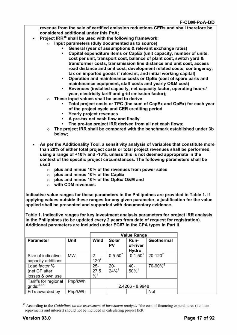
Indicative value ranges for these parameters in the Philippines are provided in Table 1. If applying values outside these ranges for any given parameter, a justification for the value applied shall be presented and supported with documentary evidence. Table 1. Indicative ranges for key investment analysis parameters for project IRR analysis in the Philippines (to be updated every 2 years from date of request for registration). Additional parameters are included under EC#7 in the CPA types in Part II.
Value Range Parameter Unit Wind Solar
PV Run-of-river Hydro
Geothermal
Size of indicative capacity additions
MW 2-1207
0.5-507 0.1-501 20-1207
Load factor % (net CF after losses & own use
25-27.5%1
20-24%1
40-50%1
70-90%6
Tariffs for regional grids:2,3,4
Php/kWh 2.4266 - 8.9948
FiTs awarded by Php/kWh Not
35 According to the Guidelines on the assessment of investment analysis “the cost of financing expenditures (i.e. loan
repayments and interest) should not be included in calculating project IRR”
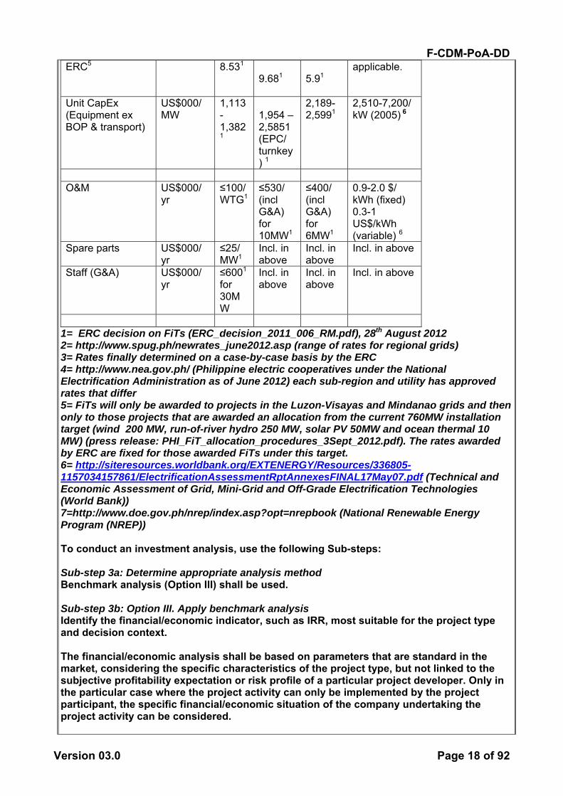
F-CDM-PoA-DD
Version 03.0 Page 18 of 92
ERC5 8.531 9.681
5.91
applicable.
Unit CapEx (Equipment ex BOP & transport)
US$000/ MW
1,113-1,3821
1,954 – 2,5851 (EPC/ turnkey) 1
2,189-2,5991
2,510-7,200/ kW (2005) 6
O&M US$000/
yr ≤100/ WTG1
≤530/ (incl G&A) for 10MW1
≤400/ (incl G&A) for 6MW1
0.9-2.0 $/ kWh (fixed) 0.3-1 US$/kWh (variable) 6
Spare parts US$000/ yr
≤25/ MW1
Incl. in above
Incl. in above
Incl. in above
Staff (G&A) US$000/ yr
≤6001
for 30MW
Incl. in above
Incl. in above
Incl. in above
1= ERC decision on FiTs (ERC_decision_2011_006_RM.pdf), 28th August 2012 2= http://www.spug.ph/newrates_june2012.asp (range of rates for regional grids) 3= Rates finally determined on a case-by-case basis by the ERC 4= http://www.nea.gov.ph/ (Philippine electric cooperatives under the National Electrification Administration as of June 2012) each sub-region and utility has approved rates that differ 5= FiTs will only be awarded to projects in the Luzon-Visayas and Mindanao grids and then only to those projects that are awarded an allocation from the current 760MW installation target (wind 200 MW, run-of-river hydro 250 MW, solar PV 50MW and ocean thermal 10 MW) (press release: PHI_FiT_allocation_procedures_3Sept_2012.pdf). The rates awarded by ERC are fixed for those awarded FiTs under this target. 6= http://siteresources.worldbank.org/EXTENERGY/Resources/336805-1157034157861/ElectrificationAssessmentRptAnnexesFINAL17May07.pdf (Technical and Economic Assessment of Grid, Mini-Grid and Off-Grade Electrification Technologies (World Bank)) 7=http://www.doe.gov.ph/nrep/index.asp?opt=nrepbook (National Renewable Energy Program (NREP)) To conduct an investment analysis, use the following Sub-steps: Sub-step 3a: Determine appropriate analysis method Benchmark analysis (Option III) shall be used. Sub-step 3b: Option III. Apply benchmark analysis Identify the financial/economic indicator, such as IRR, most suitable for the project type and decision context. The financial/economic analysis shall be based on parameters that are standard in the market, considering the specific characteristics of the project type, but not linked to the subjective profitability expectation or risk profile of a particular project developer. Only in the particular case where the project activity can only be implemented by the project participant, the specific financial/economic situation of the company undertaking the project activity can be considered.

F-CDM-PoA-DD
Version 03.0 Page 19 of 92
Discount rates and benchmarks shall be derived from: (a) Government bond rates, increased by a suitable risk premium to reflect private
investment and/or the project type, as substantiated by an independent (financial) expert or documented by official publicly available financial data;
(b) Estimates of the cost of financing and required return on capital (e.g. commercial lending rates and guarantees required for the country and the type of project activity concerned), based on bankers views and private equity investors/funds’ required return on comparable projects;
(c) A company internal benchmark (weighted average capital cost of the company), only in the particular case referred to above. The project developers shall demonstrate that this benchmark has been consistently used in the past, i.e. that project activities under similar conditions developed by the same company used the same benchmark;
(d) Government/official approved benchmark where such benchmarks are used for investment decisions;
(e) Any other indicators, if the project participants can demonstrate that the above Options are not applicable and their indicator is appropriately justified.
If for a CPA the project-based internal rate of return (IRR) without carbon credits is below an appropriate benchmark for the host country, the project shall be considered additional under this PoA. Philippine benchmarks For CPA proponents in the Philippines, project IRR pre-tax benchmarks for investment analyses have been determined at the PoA level for each of the CPA types 1 to 3 using NREB (government agency) data and analyses that were the basis of their petition to the ERC to determine FiTs for these technology types. CPA types 4-6 benchmarks shall be determined at the CPA level due to lack of a government analysis of these technologies. The benchmarks determined by NREB (source references are contained in the CPA#1 IRR analysis file) are:
• CPA type 1: wind 14%; • CPA type 2: run-of-river hydro 13.9%; and • CPA type 3: solar PV 13.4%.
The PoA-level benchmarks are to be reviewed and updated every two years at the time of updating the parameters in Table 1.
Given these IRR benchmark values and their relevance from the various perspectives of the stakeholders in the Philippines energy sector, our assumed benchmarks are reasonable and conservative. CPA proponents of types 1-3 in the Philippines that elect to confirm their additionality by performing a benchmark investment analysis must demonstrate that their project IRR does not exceed these benchmarks established at the PoA level. Proponents of CPA types 4-6 electing to perform such an analysis shall establish the benchmark at the CPA level prior to demonstrating additionality. Sub-step 3c: Calculation and comparison of financial indicators

F-CDM-PoA-DD
Version 03.0 Page 20 of 92
Calculate the suitable financial indicator for the proposed CDM project activity. Include all relevant costs (including, for example, the investment cost, the operations and maintenance costs), and revenues (excluding CER revenues, but possibly including inter alia subsidies/fiscal incentives,36 ODA, etc, where applicable), and, as appropriate, non-market cost and benefits in the case of public investors if this is standard practice for the selection of public investments in the host country. Present the investment analysis in a transparent manner and provide all the relevant assumptions, preferably in the CDM-PDD, or in separate annexes to the CDM-PDD, so that a reader can reproduce the analysis and obtain the same results. Refer to all critical techno-economic parameters and assumptions (such as capital costs, fuel prices, lifetimes, and discount rate or cost of capital). Justify and/or cite assumptions in a manner that can be validated by the DOE. In calculating the financial/economic indicator, the project’s risks can be included through the cash flow pattern, subject to project-specific expectations and assumptions (e.g. insurance premiums can be used in the calculation to reflect specific risk equivalents). Assumptions and input data for the investment analysis shall not differ across the project activity and its alternatives, unless differences can be well substantiated. Present in the CDM-PDD submitted for validation a clear comparison of the financial indicator for the proposed CDM activity and the financial benchmark. If the CDM project activity has a less favourable indicator (e.g. lower IRR) than the benchmark, then the CDM project activity cannot be considered as financially attractive. Sub-step 3d: Sensitivity analysis Include a sensitivity analysis that shows whether the conclusion regarding the financial/economic attractiveness is robust to reasonable variations in the critical assumptions. The investment analysis provides a valid argument in favour of additionality only if it consistently supports (for a realistic range of assumptions) the conclusion that the project activity is unlikely to be the most financially/economically attractive (as per Step 3c) or is unlikely to be financially/economically attractive (as per Step 3c). Outcome of Step 3: If after the sensitivity analysis it is concluded that: (1) the proposed CDM project activity is unlikely to be the most financially/economically attractive (as per Step 3c) or is unlikely to be financially/economically attractive (as per Step 3c), then proceed to Step 4 (Common practice analysis).37 Otherwise, unless barrier analysis above is undertaken and indicates that the proposed project activity faces barriers that do not prevent at least one alternative from occurring, the project activity is considered not additional. Step 4 (substeps a and b): Common practice For all CPAs, a common practice analysis shall be performed for the specific technology to be utilized in the CPA. This analysis shall be carried out with respect to the geographical boundary of the grid to which the CPA will be connected. The above generic additionality tests shall be complemented with an analysis of the extent to which the proposed project type (e.g. technology or practice) has already diffused in the relevant sector and region. This test is a credibility check to complement the investment analysis (Step 3) or barrier analysis (Step 2). Identify and discuss the existing common practice through the following Sub-steps. If the proposed project activity(ies) applies measure(s) that are listed in the definitions section of the Tool for the demonstration and assessment of additionality proceed to Sub-step 4a; otherwise, proceed to Sub-step 4b.
36 See EB guidance on the consideration of national/local/sectoral policies and measures for the baseline setting. 37 If the project participants so wish, they may apply Step 2 (Barrier analysis) as well.
F-CDM-PoA-DD
Version 03.0 Page 21 of 92
Sub-step 4a: The proposed CDM activity(ies) applies measure(s) that are listed in the definitions section of the Tool for the demonstration and assessment of additionality The latest version of the “Guidelines on common practice” available on the UNFCCC website shall be applied. Proceed directly to the outcome of Step 4. Sub-step 4b: The proposed CDM project activity(ies) does not apply any of the measures that are listed in the Tool for the demonstration and assessment of additionality Provide an analysis to which extent similar activities to the proposed CDM project activity have been implemented previously or are currently underway. Similar activities are defined as activities (i.e. technologies or practices) that are of similar scale, take place in a comparable environment, inter alia, with respect to the regulatory framework and are undertaken in the applicable geographical area, as defined above. Other CDM project activities (registered project activities and project activities which have been published on the UNFCCC website for global stakeholder consultation as part of the validation process) are not to be included in this analysis. Provide documented evidence and, where relevant, quantitative information. On the basis of that analysis, describe whether and to which extent similar activities have already diffused in the applicable geographical area. If similar activities to the proposed project activity are identified, then compare the proposed project activity to the other similar activities and assess whether there are essential distinctions between the proposed project activity and the similar activities. If this is the case, point out and explain the essential distinctions between the proposed project activity and the similar activities and explain why the similar activities enjoyed certain benefits that rendered them financially attractive (e.g., subsidies or other financial flows) and which the proposed project activity cannot use or why the similar activities did not face barriers to which the proposed project activity is subject. Essential distinctions may include a serious change in circumstances under which the proposed CDM project activity will be implemented when compared to circumstances under which similar projects were carried out. For example, new barriers may have arisen, or promotional policies may have ended, leading to a situation in which the proposed CDM project activity would not be implemented without the incentive provided by the CDM. The change must be fundamental and verifiable. The proposed project activity is regarded as “common practice” if similar activities can be observed and essential distinctions between the proposed CDM project activity and similar activities cannot be identified. Outcome of Step 4: If outcome of Step 4 is that the proposed project activity is not regarded as “common practice”, then the proposed project activity is additional. 65. If outcome of Step 4 is that the proposed project activity is regarded as “common practice” then the proposed CDM project activity is not additional. Common Practice in the Philippines38 In this section we assess common practice at the PoA level, in accordance with the Guidelines on Common Practice version 2.0. More detailed information for each CPA type is provided in texts for each generic CPA (Parts II through VII).
38 The descriptions and calculation results presented in this section are based on data from the Philippines Department
of Energy. The data (including plant investment types (government, non-profit cooperative and private)) and detailed analysis are available to the DOE for validation.

F-CDM-PoA-DD
Version 03.0 Page 22 of 92
As explained in Part I Section A.2, the Philippines is an island-based country containing two main regional grid systems (the interconnected grid covering Luzon and Visayas, and the regional grid on Mindanao) and many additional smaller regional grids. The penetration and regional distribution of the existing installations of the PoA-eligible technologies in the Philippines is highly influenced by the regional resource bases and market conditions, which differ considerably amongst the isolated island regions of the country. Also explained in Part I Section A.2, nearly all electric power facilities in the Philippines were owned by government bodies or non-profit electric co-operatives until the entry into force of the Electric Power Industry Reform Act (EPIRA) in September 2001. Even after the passing of this Act, the private sector’s appetite for commercial investments in renewable power production has been slow to develop. Very few of the newer, post-EPIRA, renewable-energy power plants were established as commercial investments, and those that were established as CDM projects. With the exception of CDM projects, there are currently no power plants that were invested in on a commercial basis anywhere in the Philippines employing the following technologies:
• Wind (CPA type 1) • Large-scale run-of-river hydro (CPA type 2) • Solar PV (CPA type 3) • Wave (CPA type 4) • Tidal (CPA type 5) • Geothermal (CPA type 6)
Therefore, these technologies are clearly not common practice in any of the grid systems in the Philippines. With the exception of small-scale hydro, the regional grids in the Philippines do not have any of the PoA-eligible technologies installed, relying almost 100% on diesel power generation.39 Therefore a CPA utilizing any of the other PoA-eligible technologies in any of the regional grid systems outside of Luzon-Visayas and Mindanao cannot be considered as common practice. Small-scale hydro (part of CPA type 2): There may be small-scale hydro power plants invested in commercially outside the Luzon-Visayas and Mindanao regions40 However, there have been no commercial investments in small-scale hydro power in either Luzon-Visayas or Mindanao so private investments in small-scale hydropower plants are not common practice in either of these regional grids. For small-scale type 2 CPAs that will connect to other regional grids, common practice analysis shall be performed at the CPA level. An updated common practice analysis for the PoA-eligible technologies determined above to be not common practice for CPAs in the Philippines shall be provided at the end of each seven-year crediting period of this PoA. CPAs applying PoA-eligible technologies that are not approved micro-scale technologies in their host country and have not been demonstrated here to be not common practice shall provide a common practice analysis in accordance with the Guidelines on Common Practice that are current at the time of application for inclusion in this PoA.
B.2. Eligibility criteria for inclusion of a CPA in the PoA
39 Provided to the DOE for validation 40 We are unable to document this because the Philippines Department of Energy only maintains a comprehensive
database on the Luzon-Visayas and Mindanao regional grids: not the other regional grids in the country.
F-CDM-PoA-DD
Version 03.0 Page 23 of 92
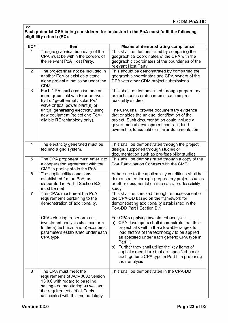
>> Each potential CPA being considered for inclusion in the PoA must fulfil the following eligibility criteria (EC):
EC# Item Means of demonstrating compliance 1 The geographical boundary of the
CPA must be within the borders of the relevant PoA Host Party.
This shall be demonstrated by comparing the geographical coordinates of the CPA with the geographic coordinates of the boundaries of the relevant Host Party
2 The project shall not be included in another PoA or exist as a stand-alone project submission under the CDM.
This should be demonstrated by comparing the geographic coordinates and CPA owners of the CPA with other CDM project submissions
3 Each CPA shall comprise one or more greenfield wind/ run-of-river hydro / geothermal / solar PV/ wave or tidal power plant(s) or unit(s) generating electricity using new equipment (select one PoA-eligible RE technology only).
This shall be demonstrated through preparatory project studies or documents such as pre-feasibility studies. The CPA shall provide documentary evidence that enables the unique identification of the project. Such documentation could include a governmental development contract, land ownership, leasehold or similar documentation.
4 The electricity generated must be fed into a grid system.
This shall be demonstrated through the project design, supported through studies or documentation such as pre-feasibility studies
5 The CPA proponent must enter into a cooperation agreement with the CME to participate in the PoA
This shall be demonstrated through a copy of the PoA Participation Contract with the CME
6 The applicability conditions established for the PoA, as elaborated in Part II Section B.2, must be met
Adherence to the applicability conditions shall be demonstrated through preparatory project studies or other documentation such as a pre-feasibility study
7 The CPAs must meet the PoA requirements pertaining to the demonstration of additionality. CPAs electing to perform an investment analysis shall conform to the a) technical and b) economic parameters established under each CPA type
This shall be checked through an assessment of the CPA-DD based on the framework for demonstrating additionality established in the PoA-DD Part I Section B.1 For CPAs applying investment analysis: a) CPA developers shall demonstrate that their
project falls within the allowable ranges for load factors of the technology to be applied as specified under each generic CPA type in Part II.
b) Further they shall utilize the key items of capital expenditure that are specified under each generic CPA type in Part II in preparing their analysis
8 The CPA must meet the
requirements of ACM0002 version 13.0.0 with regard to baseline setting and monitoring as well as the requirements of all Tools associated with this methodology
This shall be demonstrated in the CPA-DD
F-CDM-PoA-DD
Version 03.0 Page 24 of 92
9 The reported start date of the CPA
must be supported by documentary evidence, such as a project schedule.
The status of various tasks leading up to commencement of the project should be reflected in the CME’s CPA process management template to confirm that the reported start date is realistic
10 The CPAs must have complied with CDM and host country requirements to hold a local stakeholder consultation
This shall be demonstrated through documentary evidence such as: copies of invitations to stakeholder dialogues, newspaper announcements, signed and dated meeting participation lists, photographs, meeting minutes
11 The CPAs must have complied with host country requirements to assess potential environmental impacts of the project activity
This shall be demonstrated through documentary evidence of the host country requirements as well as approval, in for example the form of a license or environmental compliance certificate
12 The CPA owner must provide the CME with a declaration as to whether or not the CPA will receive donor funding
For CPAs that are funded partially or wholly with donor funding, the CPA owner must provide the CME with written confirmation from the Annex I party that the funding provided does not result in a diversion of official development assistance
The conditions related to sampling requirements for a CPA are not relevant as each CPA will be monitored individually.
B.3. Application of methodologies >> As indicated in Part I Sections A.2 and A.6, this PoA is applicable to CPAs employing the following renewable energy technologies and selling electricity to a grid system:
• Wind; • Run-of-river hydro; • Solar PV; • Wave; • Tidal; and • Geothermal;
Further, this PoA is restricted to CPAs that meet the applicability criteria established for methodologyACM0002 Consolidated baseline methodology for grid-connected electricity generation from renewable sources --- Version 13.0.0. This methodology is applicable for all of the technologies listed above.
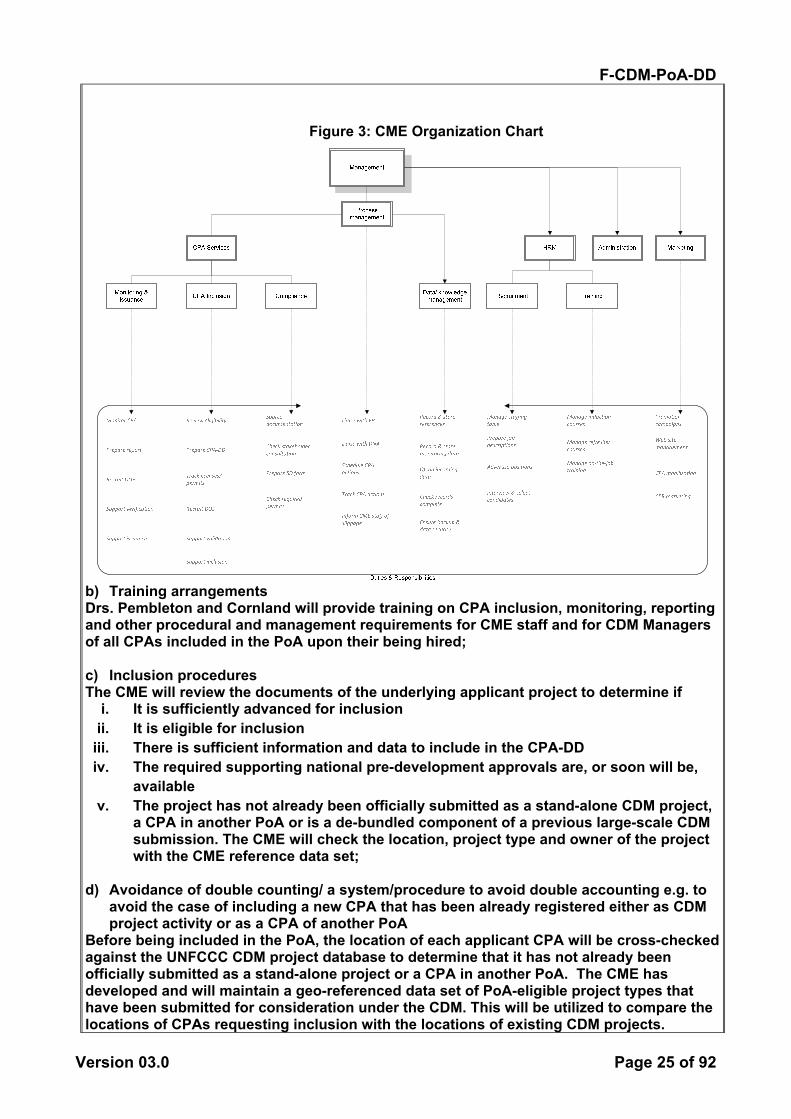
SECTION C. Management system >> a) Roles and responsibilities The PoA will initially be undertaken by Dr. Peter Pembleton, CEO of Carbonergy Business Consultancy Services (CBCS, in the Philippines) and Dr. Deborah Cornland, Director of Cornland International (CI, in Sweden), the originators and authors of this PoA. Additional staff will be recruited once the volume of work increases to a level that justifies recruitment. Specific roles and responsibilities of the CME are shown in the following organization chart (figure 3).
F-CDM-PoA-DD
Version 03.0 Page 25 of 92
Figure 3: CME Organization Chart
b) Training arrangements Drs. Pembleton and Cornland will provide training on CPA inclusion, monitoring, reporting and other procedural and management requirements for CME staff and for CDM Managers of all CPAs included in the PoA upon their being hired; c) Inclusion procedures The CME will review the documents of the underlying applicant project to determine if
i. It is sufficiently advanced for inclusion ii. It is eligible for inclusion
iii. There is sufficient information and data to include in the CPA-DD iv. The required supporting national pre-development approvals are, or soon will be,
available v. The project has not already been officially submitted as a stand-alone CDM project,
a CPA in another PoA or is a de-bundled component of a previous large-scale CDM submission. The CME will check the location, project type and owner of the project with the CME reference data set;
d) Avoidance of double counting/ a system/procedure to avoid double accounting e.g. to
avoid the case of including a new CPA that has been already registered either as CDM project activity or as a CPA of another PoA
Before being included in the PoA, the location of each applicant CPA will be cross-checked against the UNFCCC CDM project database to determine that it has not already been officially submitted as a stand-alone project or a CPA in another PoA. The CME has developed and will maintain a geo-referenced data set of PoA-eligible project types that have been submitted for consideration under the CDM. This will be utilized to compare the locations of CPAs requesting inclusion with the locations of existing CDM projects.

F-CDM-PoA-DD
Version 03.0 Page 26 of 92
e) Records management and control/ a record keeping system for each CPA under the
PoA The CME will develop and maintain an electronic data storage and retrieval system that will, inter alia, include the following key data elements for each CPA
• Name of the CPA • Site location/ coordinates (GPS coordinates of the power house and the water
intake) • Owner/ developer name and contact details • Project status and progress through the CDM cycle • Installed capacity • Meter measurements of electricity supplied to grid • Sales records of electricity sold; and • Records documenting meter calibrations.
f) Continuous improvement of system A generic project management template has been developed reflecting the different stages of inclusion, monitoring, verification and issuance for a CPA. The template will be used on a day-to-day basis to monitor progress, determine and address any slippage and improve the overall CPA management process over time. g) Others/ provisions to ensure that those operating the CPA are aware and have agreed
that their activity is being subscribed to the PoA The Proponent of each proposed CPA will be required to enter into a PoA Participation Contract with the CME that includes sections on responsibilities and warranties among the contracted terms of participation. The CPA Process & Management Manual contains more information on the CPA management system.
SECTION D. Duration of PoA
D.1. Start date of PoA >> 17/07/2012 (the date of PoA publication for global stakeholder consultation).
D.2. Duration of the PoA >> The PoA is expected to last 28 years from the start date.

F-CDM-PoA-DD
Version 03.0 Page 27 of 92
SECTION E. Environmental impacts
E.1. Level at which environmental analysis is undertaken >> Environmental Analysis is done at CPA level. The Philippines Department of Environment and Natural Resources (DENR) requires all projects to apply for approval under its Environmental Impact Statement (EIS) system41 (which is equivalent to an Environmental Impact Assessment (EIA) system). Therefore, performing the environmental analysis at the CPA level is appropriate.
E.2. Analysis of the environmental impacts >> N/A
E.3. Environmental impact assessment >> N/A
SECTION F. Local stakeholder comments
F.1. Solicitation of comments from local stakeholders >> Local stakeholder consultation is done at CPA level. While the Philippine DNA has not yet developed specific procedures for PoAs, they do have strong concerns about the correct conduct of stakeholder consultations to the extent that they require “the physical presence of stakeholders” with various levels of evidence.42 The required level of information can only be obtained at the CPA level. Therefore, performing stakeholder consultations at the CPA level is appropriate.
F.2. Summary of comments received >> N/A
F.3. Report on consideration of comments received >> N/A
41http://www.google.at/url?sa=t&rct=j&q=&esrc=s&source=web&cd=1&sqi=2&ved=0CE0QFjAA&url=http%3A%2F
%2Femb.gov.ph%2Flaws%2Fenvironmental%2520impact%2520assessment%2FDAO30.doc&ei=9LvmT8XrE8bO4QTv_6nPAQ&usg=AFQjCNFc0SYlE3JtHbfa67IXCqAKYfBEIg
42 Interim Guidelines On The Conduct Of Stakeholders’ Consultation Under DAO 2005-17, http://cdmdna.emb.gov.ph/cdm/public/cdm-techResources.php?main=tech&ListCategories=03

F-CDM-PoA-DD
Version 03.0 Page 28 of 92
SECTION G. Approval and authorization >> Two Parties are involved in this PoA: the Host Party of the first CPA, the Republic of the Philippines and Sweden. The Letters of Approval (LoAs) were not available at the time of submitting the PoA-DD to the DOE for validation.
F-CDM-PoA-DD
Version 03.0 Page 29 of 92
PART II. Generic component project activity (CPA)
For CPA type 1 (wind)
SECTION A. General description of a generic CPA
A.1. Purpose and general description of generic CPAs >> The generic purpose of CPAs included in this PoA is to support the development of renewable energy projects that feed electric power into a grid in the Host Country. In general, the PoA enables developers of such CPAs to overcome financial and other barriers to developing and implementing their projects, by harnessing the financial support made available through the sale of carbon credits.
SECTION B. Application of a baseline and monitoring methodology
B.1. Reference of the approved baseline and monitoring methodology(ies) selected >> For all of the applicable technologies in this PoA: ACM0002 Consolidated baseline methodology for grid-connected electricity generation from renewable sources --- Version 13.0.0 The latest approved versions of the following tools are referred to in this methodology:
• The Tool to calculate the emission factor for an electricity system (current version: 03.0.0)
• The Tool for the demonstration and assessment of additionality (current version: 07.0.0)
• The Combined tool to identify the baseline scenario and demonstrate additionality (current version: 5.0.0)43
• The Tool to calculate project or leakage CO2 emissions from fossil fuel combustion (current version: 2).
B.2. Application of methodology(ies) >> Compliance with the applicability conditions in ACM0002 Version 13.0.0 and all associated Tools is included as an eligibility requirement for all CPAs applying for inclusion in this PoA. Table 2. Relevance of ACM0002 to the proposed PoA Applicability Condition from the Meth Relevance to Proposed PoA
43 This tool is only applicable to project activities that involve the retrofit or replacement of existing grid-connected
renewable power plant/unit(s) at the project site. As such projects are not eligible under this PoA, this tool is not applied.
F-CDM-PoA-DD
Version 03.0 Page 30 of 92
This methodology is applicable to grid-connected renewable power generation project activities that: (a) install a new power plant at a site where no renewable power plant was operated prior to the implementation of the project activity (greenfield plant); (b) involve a capacity addition; (c) involve a retrofit of (an) existing plant(s); or (d) involve a replacement of (an) existing plant(s).
The proposed PoA is applicable to project activities that install a new power plant at a site where there was no renewable energy power plant operating prior to the implementation of the project activity (Greenfield plant). The proposed PoA is not applicable to project activities that involve capacity additions, retrofits of existing plants, or replacements of existing plants. Adherence to this condition shall be confirmed through supporting studies or documentation such as feasibility studies and/or business plans.
The methodology is applicable under the following conditions: • The project activity is the installation,
capacity addition, retrofit or replacement of a power plant/unit of one of the following types: hydro power plant/unit (either with a run-of-river reservoir or an accumulation reservoir), wind power plant/unit, geothermal power plant/unit, solar power plant/unit, wave power plant/unit or tidal power plant/unit;
• In the case of capacity additions, retrofits or replacements (except for wind, solar, wave or tidal power capacity addition projects which use Option 2 on page 10 of version 13.0.0 of the methodology to calculate the parameter EGPJ,y): the existing plant started commercial operation prior to the start of a minimum historical reference period of five years, used for the calculation of baseline emissions and defined in the baseline emission section, and no capacity expansion or retrofit of the plant has been undertaken between the start of this minimum historical reference period and the implementation of the project activity.;
The proposed PoA is applicable to installation of greenfield run-of-river hydro, wind, geothermal, solar PV, wave and tidal power plants/units supplying electricity to a grid. The PoA is not applicable to solar thermal projects. The PoA is not applicable to hydropower projects that create new accumulation reservoirs or increase the volume of an existing reservoir. Adherence to this condition shall be confirmed through supporting studies or documentation such as feasibility studies and/or business plans.
In case of hydro power plants: • One of the following conditions must apply:
o The project activity is implemented in an existing single or multiple reservoirs, with no change in the volume of any of the reservoirs; or
o The project activity is implemented in an existing single or multiple reservoirs, where the volume of any of the reservoirs is increased and the power density of each reservoir, as per the definitions given in the project emissions section, is greater than 4 W/m2; or
o The project activity results in new single
As this CPA type does not relate to hydro this applicability condition does not apply.

F-CDM-PoA-DD
Version 03.0 Page 31 of 92
or multiple reservoirs and the power density of each reservoir, as per the definitions given in the project emissions section, is greater than 4 W/m2.
In case of hydro power plants using multiple reservoirs where the power density of any of the reservoirs is lower than 4 W/m2 all of the following conditions must apply:
• The power density calculated for the entire project activity using equation 5 is greater than 4 W/m2;
• Multiple reservoirs and hydro power plants located at the same river and where are designed together to function as an integrated project that collectively constitute the generation capacity of the combined power plant;
• Water flow between multiple reservoirs is not used by any other hydropower unit which is not a part of the project activity;
• Total installed capacity of the power units, which are driven using water from the reservoirs with a power density lower than 4 W/m2, is lower than 15 MW;
• Total installed capacity of the power units, which are driven using water from reservoirs with a power density lower than 4 W/m2, is less than 10% of the total installed capacity of the project activity from multiple reservoirs.
As this CPA type does not relate to hydro this applicability condition does not apply.
The methodology is not applicable to the following: • Project activities that involve switching from
fossil fuels to renewable energy sources at the site of the project activity, since in this case the baseline may be the continued use of fossil fuels at the site;
• Biomass fired power plants; • A hydro power plant that results in the
creation of a new single reservoir or in the increase in an existing single reservoir where the power density of the reservoir is less than 4 W/m2.
As this CPA type relates to non-biomass non-hydro greenfield projects, this applicability condition is met.
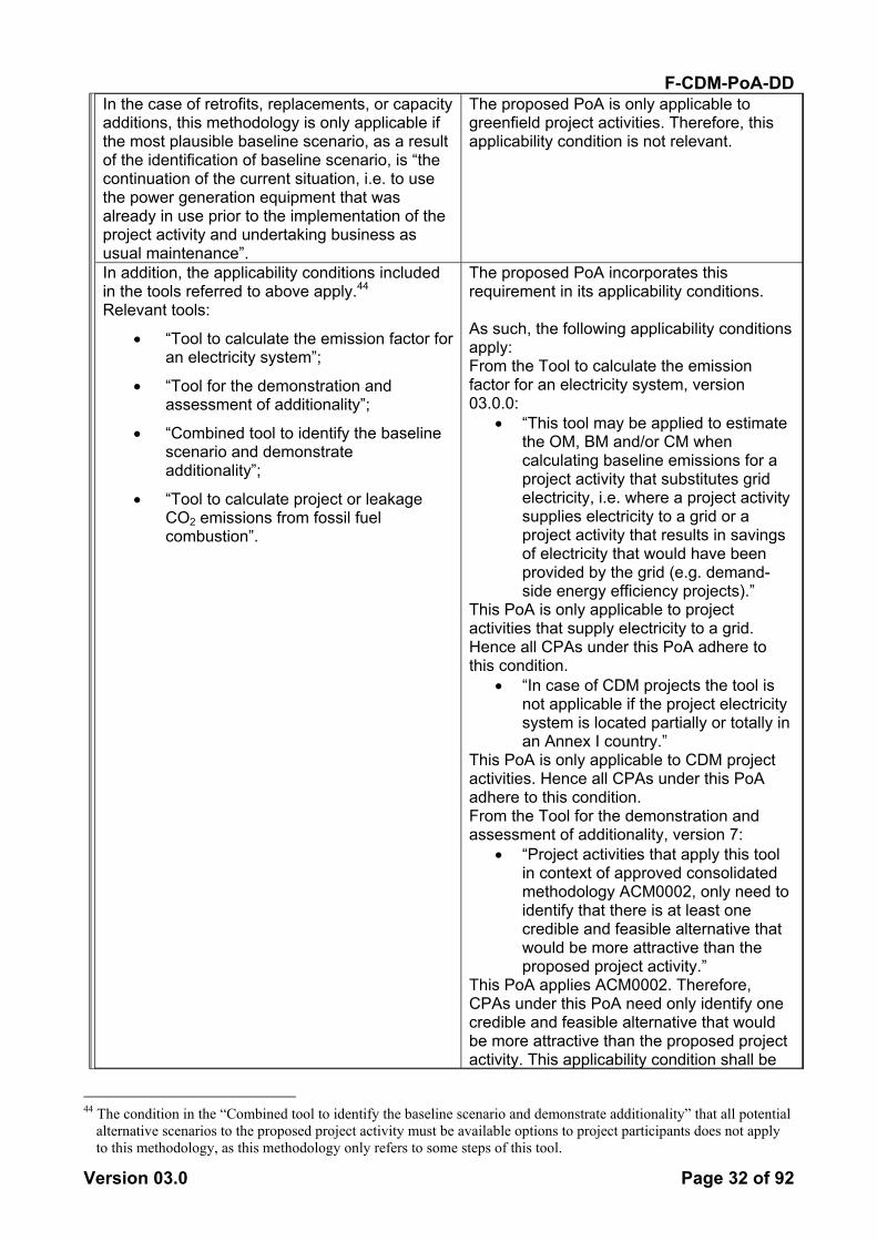
F-CDM-PoA-DD
Version 03.0 Page 32 of 92
In the case of retrofits, replacements, or capacity additions, this methodology is only applicable if the most plausible baseline scenario, as a result of the identification of baseline scenario, is “the continuation of the current situation, i.e. to use the power generation equipment that was already in use prior to the implementation of the project activity and undertaking business as usual maintenance”.
The proposed PoA is only applicable to greenfield project activities. Therefore, this applicability condition is not relevant.
In addition, the applicability conditions included in the tools referred to above apply.44 Relevant tools:
• “Tool to calculate the emission factor for an electricity system”;
• “Tool for the demonstration and assessment of additionality”;
• “Combined tool to identify the baseline scenario and demonstrate additionality”;
• “Tool to calculate project or leakage CO2 emissions from fossil fuel combustion”.
The proposed PoA incorporates this requirement in its applicability conditions. As such, the following applicability conditions apply: From the Tool to calculate the emission factor for an electricity system, version 03.0.0:
• “This tool may be applied to estimate the OM, BM and/or CM when calculating baseline emissions for a project activity that substitutes grid electricity, i.e. where a project activity supplies electricity to a grid or a project activity that results in savings of electricity that would have been provided by the grid (e.g. demand-side energy efficiency projects).”
This PoA is only applicable to project activities that supply electricity to a grid. Hence all CPAs under this PoA adhere to this condition.
• “In case of CDM projects the tool is not applicable if the project electricity system is located partially or totally in an Annex I country.”
This PoA is only applicable to CDM project activities. Hence all CPAs under this PoA adhere to this condition. From the Tool for the demonstration and assessment of additionality, version 7:
• “Project activities that apply this tool in context of approved consolidated methodology ACM0002, only need to identify that there is at least one credible and feasible alternative that would be more attractive than the proposed project activity.”
This PoA applies ACM0002. Therefore, CPAs under this PoA need only identify one credible and feasible alternative that would be more attractive than the proposed project activity. This applicability condition shall be
44 The condition in the “Combined tool to identify the baseline scenario and demonstrate additionality” that all potential
alternative scenarios to the proposed project activity must be available options to project participants does not apply to this methodology, as this methodology only refers to some steps of this tool.
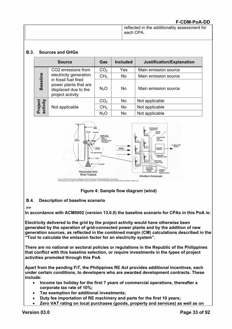
F-CDM-PoA-DD
Version 03.0 Page 33 of 92
reflected in the additionality assessment for each CPA.
B.3. Sources and GHGs
Source Gas Included Justification/Explanation
Bas
elin
e
CO2 emissions from electricity generation in fossil fuel fired power plants that are displaced due to the project activity
CO2 Yes Main emission source CH4 No Main emission source
N2O No Main emission source
Proj
ect
activ
ity
Not applicable CO2 No Not applicable CH4 No Not applicable N2O No Not applicable
Figure 4: Sample flow diagram (wind)
B.4. Description of baseline scenario >> In accordance with ACM0002 (version 13.0.0) the baseline scenario for CPAs in this PoA is: Electricity delivered to the grid by the project activity would have otherwise been generated by the operation of grid-connected power plants and by the addition of new generation sources, as reflected in the combined margin (CM) calculations described in the “Tool to calculate the emission factor for an electricity system”. There are no national or sectoral policies or regulations in the Republic of the Philippines that conflict with this baseline selection, or require investments in the types of project activities promoted through this PoA. Apart from the pending FiT, the Philippines RE Act provides additional incentives, each under certain conditions, to developers who are awarded development contracts. These include:
• Income tax holiday for the first 7 years of commercial operations, thereafter a corporate tax rate of 10%;
• Tax exemption for additional investments; • Duty fee importation of RE machinery and parts for the first 10 years; • Zero VAT rating on local purchases (goods, property and services) as well as on

F-CDM-PoA-DD
Version 03.0 Page 34 of 92
power sold. However, all of these policies, including the FiT, were established after the adoption by the COP of the CDM M&P (decision 17/CP.7, 11 November 2001) and therefore need not be taken into account in establishing a baseline scenario.45 For CPAs connected to the Luzon-Visayas integrated grid or the Mindoro regional grid, the grid emission factor has been established at the PoA-level. Details of how the Tool to calculate the emission factor for an electricity system has been applied for these two grid systems are provided in section B.6.1, below. For CPAs connected to any other regional grid system, the grid emission factor will be calculated at the CPA-level.
B.5. Demonstration of eligibility for a generic CPA >> Confirming compliance with the PoA eligibility criteria: Each CPA proponent must submit a complete CPA-DD and the supporting documentation called for under the eligibility criteria presented in Part I Section B.2 and demonstrate compliance filling in the Compliance check column in table 4. Table 4. Eligibility compliance check (wind CPAs) EC# Item Means of demonstrating
compliance Compliance check
1 The geographical boundary of the CPA must be within the borders of the relevant PoA Host Party.
This shall be demonstrated by comparing the geographical coordinates of the CPA with the geographic coordinates of the boundaries of the relevant Host Party
[Refer to relevant supporting documentation]
2 The project shall not be included in another PoA or exist as a stand-alone project submission under the CDM.
This should be demonstrated by comparing the geographic coordinates and CPA owners of the CPA with other CDM project submissions
[Refer to relevant supporting documentation]
3 Each CPA shall comprise one or more greenfield power plant(s) or unit(s) generating electricity using new equipment.
This shall be demonstrated through preparatory project studies or documents such as pre-feasibility studies. The CPA shall provide documentary evidence that enables the unique identification of the project. Such documentation could include a governmental development contract, land ownership, leasehold or similar documentation.
[Refer to relevant supporting documentation]
4 The electricity generated must be fed into a grid
This shall be demonstrated through the project design,
[Refer to relevant supporting
45 See EB65 Annex 5 paragraph 45(b)
http://cdm.unfccc.int/filestorage/Q/9/N/Q9NO4DL7S15VKA23MGE6PW8YIFTCRH/eb65_repan05.pdf?t=cnR8bTllanE4fDC0ExuMpbtb35nZNPeHpzhE
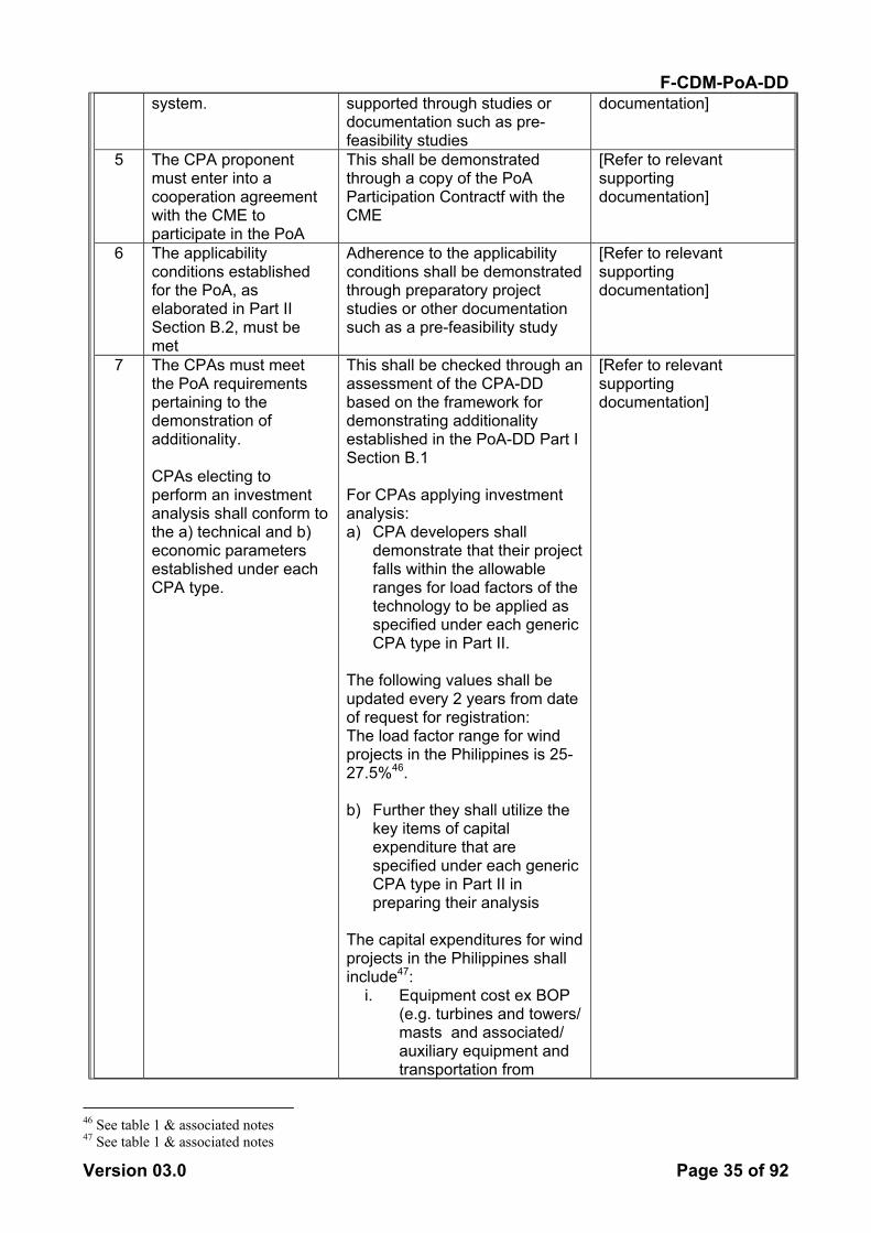
F-CDM-PoA-DD
Version 03.0 Page 35 of 92
system. supported through studies or documentation such as pre-feasibility studies
documentation]
5 The CPA proponent must enter into a cooperation agreement with the CME to participate in the PoA
This shall be demonstrated through a copy of the PoA Participation Contractf with the CME
[Refer to relevant supporting documentation]
6 The applicability conditions established for the PoA, as elaborated in Part II Section B.2, must be met
Adherence to the applicability conditions shall be demonstrated through preparatory project studies or other documentation such as a pre-feasibility study
[Refer to relevant supporting documentation]
7 The CPAs must meet the PoA requirements pertaining to the demonstration of additionality. CPAs electing to perform an investment analysis shall conform to the a) technical and b) economic parameters established under each CPA type.
This shall be checked through an assessment of the CPA-DD based on the framework for demonstrating additionality established in the PoA-DD Part I Section B.1 For CPAs applying investment analysis: a) CPA developers shall
demonstrate that their project falls within the allowable ranges for load factors of the technology to be applied as specified under each generic CPA type in Part II.
The following values shall be updated every 2 years from date of request for registration: The load factor range for wind projects in the Philippines is 25-27.5%46. b) Further they shall utilize the
key items of capital expenditure that are specified under each generic CPA type in Part II in preparing their analysis
The capital expenditures for wind projects in the Philippines shall include47:
i. Equipment cost ex BOP (e.g. turbines and towers/ masts and associated/ auxiliary equipment and transportation from
[Refer to relevant supporting documentation]
46 See table 1 & associated notes 47 See table 1 & associated notes

F-CDM-PoA-DD
Version 03.0 Page 36 of 92
country of origin to the Philippine port) US$1,113-1,382/ kW;
ii. VAT on imported goods 30% of 12%;
iii. transportation cost to site 10% of WTG;
iv. balance of plant (engineering works) 35% of WTG;
v. switchyard & transformers range US$1.814-3.5 million;
vi. transmission lines to grid range US$69,800-84,000/ km;
vii. service/ access road US$50,000/ km +10%48;
viii. construction contingency 7.5% of total project cost;
ix. Initial working capital 1% of EPC;
x. development costs (e.g. land, permits)
2% of EPC (i-ix). 8 The CPA must meet the
requirements of ACM0002 version 13.0.0 with regard to baseline setting and monitoring as well as the requirements of all Tools associated with this methodology
This shall be demonstrated in the CPA-DD
[Refer to relevant supporting documentation]
9 The reported start date
of the CPA must be supported by documentary evidence, such as a project schedule.
The status of various tasks leading up to commencement of the project should be reflected in the CME’s CPA process management template to confirm that the reported start date is realistic
[Refer to relevant supporting documentation]
10 The CPAs must have complied with CDM and host country requirements to hold a local stakeholder consultation
This shall be demonstrated through documentary evidence such as: copies of invitations to stakeholder dialogues, newspaper announcements, signed and dated meeting participation lists, photographs, meeting minutes
[Refer to relevant supporting documentation]
11 The CPAs must have complied with host country requirements to
This shall be demonstrated through documentary evidence of the host country requirements
[Refer to relevant supporting documentation]
48 This is highly dependent upon terrain
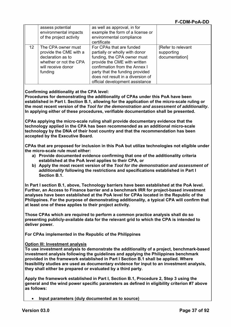
F-CDM-PoA-DD
Version 03.0 Page 37 of 92
assess potential environmental impacts of the project activity
as well as approval, in for example the form of a license or environmental compliance certificate
12 The CPA owner must provide the CME with a declaration as to whether or not the CPA will receive donor funding
For CPAs that are funded partially or wholly with donor funding, the CPA owner must provide the CME with written confirmation from the Annex I party that the funding provided does not result in a diversion of official development assistance
[Refer to relevant supporting documentation]
Confirming additionality at the CPA level: Procedures for demonstrating the additionality of CPAs under this PoA have been established in Part I. Section B.1, allowing for the application of the micro-scale ruling or the most recent version of the Tool for the demonstration and assessment of additionality. In applying either of these procedures, verifiable documentation shall be presented. CPAs applying the micro-scale ruling shall provide documentary evidence that the technology applied in the CPA has been recommended as an additional micro-scale technology by the DNA of their host country and that the recommendation has been accepted by the Executive Board. CPAs that are proposed for inclusion in this PoA but utilize technologies not eligible under the micro-scale rule must either:
a) Provide documented evidence confirming that one of the additionality criteria established at the PoA level applies to their CPA, or
b) Apply the most recent version of the Tool for the demonstration and assessment of additionality following the restrictions and specifications established in Part I Section B.1.
In Part I section B.1, above, Technology barriers have been established at the PoA level. Further, an Access to Finance barrier and a benchmark IRR for project-based investment analyses have been established at the PoA level for CPAs located in the Republic of the Philippines. For the purpose of demonstrating additionality, a typical CPA will confirm that at least one of these applies to their project activity. Those CPAs which are required to perform a common practice analysis shall do so presenting publicly-available data for the relevant grid to which the CPA is intended to deliver power. For CPAs implemented in the Republic of the Philippines Option III: Investment analysis To use investment analysis to demonstrate the additionality of a project, benchmark-based investment analysis following the guidelines and applying the Philippines benchmark provided in the framework established in Part I Section B.1 shall be applied. Where feasibility studies are used as documentary evidence for input to an investment analysis, they shall either be prepared or evaluated by a third party. Apply the framework established in Part I, Section B.1, Procedure 2, Step 3 using the general and the wind power specific parameters as defined in eligibility criterion #7 above as follows:
• Input parameters (duly documented as to source)

F-CDM-PoA-DD
Version 03.0 Page 38 of 92
o General (year of assumptions & relevant exchange rates) o Wind power specific capital expenditure items or CapEx for: wind turbines,
towers/ masts and associated/ auxiliary equipment; transportation from country of origin to the Philippine port; transport cost to site; balance of plant/ engineering cost; switch yard & transformer costs conforming to the values defined under EC#7 above);
o General CapEx for: transmission line distance and unit cost; access road distance and unit cost; development related costs; contingency; tax on imported goods if relevant; and initial working capital conforming to the values defined under EC#7 above;
o Operation and maintenance costs or OpEx (cost of spare parts and maintenance equipment, staff costs and yearly O&M cost)
o Revenues (installed capacity, net capacity factor, operating hours/ year, electricity tariff and grid emission factor);
The above input values shall be used to derive:
• Total project costs or TPC (the sum of CapEx and OpEx) for each year of the project cycle and CER crediting period;
• Yearly project revenues; • A pre-tax net cash flow; and finally • The pre-tax project IRR derived from all net cash flows.
A sensitivity analysis shall be performed as follows unless this is not deemed appropriate in the context of the specific project circumstances:
• Plus and minus 10% of the revenues from power sales; • Plus and minus 10% of the CapEx; • Plus and minus 10% of the OpEx/ O&M; and • With CDM revenues.
The pre-tax project IRR shall be compared with the benchmark established in Part I, Section B.1, Procedure 2, Step 3, Sub-step 3b. The other investment analysis options provided in the Tool may also be used. Access to Finance The Access to Finance barrier is established at the PoA level. Projects that must borrow capital from financial institutions, or turn to co-investors that demand access to carbon credits, to finance their investment face this barrier and are, therefore, additional. Project proponents proposing CPAs for inclusion in the PoA may utilize this barrier to demonstrate their project’s additionality by confirming its validity in relation to the project in question. Documented evidence must be presented. Common Practice Analysis The following common practice analysis has been carried out in accordance with the Guidelines on Common Practice version 2.0. The details of each step can be found in the guideline and are not repeated here. There is only one wind power facility in the Philippines. It is a 33MW facility connected to the Luzon-Visayas grid. Therefore, for all regions outside of the area connected to the Luzon-Visayas interconnected regional grid, wind power is clearly not common practice. Further, within Luzon-Visayas small-scale wind power production is clearly not common practice. For Luzon-Visayas: Step 1: calculate applicable capacity or output range as +/-50% of the total design capacity
F-CDM-PoA-DD
Version 03.0 Page 39 of 92
or output of the proposed project activity. For Luzon-Visayas we have analyzed one applicable output range: large scale (>15MW): Step 2: identify similar projects (both CDM and non-CDM) which fulfil all of the conditions presented in the Guideline: Large-scale: There is one 33MW wind power project connected to the Luzon-Visayas grid. This power plant started commercial operation prior to the publication of the design document for this PoA for global stakeholder consultation. Step 3: within the projects identified in Step 2, identify those that are neither registered CDM project activities, project activities submitted for registration, nor project activities undergoing validation. Note their number Nall. Large scale: The one wind power plant is registered as a CDM activity.49 Therefore, Nall = 0. As Step 3 results in no power plants for further analysis, commercial wind-power investments of any size are clearly not common practice in any of the grid systems in the Philippines.
B.6. Estimation of emission reductions of a generic CPA
B.6.1, Explanation of methodological choices >> Emission reductions are calculated as baseline emissions less project emissions and leakage. The methodological choices for each are detailed below. Project Emissions PEy = 0. Baseline emissions In accordance with methodology ACM0002 Version 13.0.0, baseline emissions include only CO2 emissions from electricity generation in fossil fuel fired power plants that are displaced due to the project activity. The methodology assumes that all project electricity generation above baseline levels would have been generated by existing grid-connected power plants and the addition of new grid-connected power plants. The baseline emissions are to be calculated as follows:
yCMgridyPJy EFEGBE ,,, *= (6)
yPJEG , = Quantity of net electricity generation that is produced and fed into the
grid as a result of the implementation of the CDM project activity in year y (MWh/yr)
Calculation of EGPJ,y
yfacility,yPJ, EGEG = (7) Where:
yPJ,EG = Quantity of net electricity generation that is produced and fed into the
grid as a result of the implementation of the CDM project activity in year y (MWh/yr)
49 NorthWind Bangui Bay Project CDM reference number 0453
F-CDM-PoA-DD
Version 03.0 Page 40 of 92
yfacility,EG = Quantity of net electricity generation supplied by the project plant/unit to
the grid in year y (MWh/yr) Calculation of the Combined Margin Grid Emission Factor (EFgrid,CM,y) The combined margin grid emission factor for the relevant grid is calculated using the Tool to calculate the emission factor for an electricity system, Version 003.0.0, as follows: Project participants shall apply the following six steps: STEP 1. Identify the relevant electricity systems; STEP 2. Choose whether to include off-grid power plants in the project electricity system (optional); STEP 3. Select a method to determine the operating margin (OM); STEP 4. Calculate the operating margin emission factor according to the selected method;STEP 5. Calculate the build margin (BM) emission factor; STEP 6. Calculate the combined margin (CM) emissions factor. As mentioned in section B.4, above, the grid emission factor has been established at the PoA-level for CPAs connected to the Luzon-Visayas integrated grid or the Mindoro regional grid. Details regarding the grid emission factor calculations (applying the Tool to calculate the emission factor for an electricity system) for these two grid systems are provided below. For CPAs connected to any other regional grid system, the grid emission factor will be calculated at the CPA-level. Step 1: Identify the relevant electricity systems For determining the electricity emission factors, identify the relevant project electricity system. A grid/project electricity system is defined by the spatial extent of the power plants that are physically connected through transmission and distribution lines to the project activity (e.g. the renewable power plant location) and that can be dispatched without significant transmission constraints. Similarly, identify any connected electricity systems. If a connected electricity system is located partially or totally in Annex I countries, then the emission factor of that connected electricity system should be considered zero. Step 2: Choose whether to include off-grid power plants in the project electricity system (optional) Project participants may choose between the following two options to calculate the operating margin and build margin emission factor: Option I: Only grid power plants are included in the calculation. Option II: Both grid power plants and off-grid power plants are included in the calculation. Step 3: Select a method to determine the operating margin (OM) The calculation of the operating margin emission factor (EFgrid,OM,y) is based on one of the following methods, which are described under Step 4 of the Tool:
(a) Simple OM; or (b) Simple adjusted OM; or (c) Dispatch data analysis OM; or (d) Average OM.
Step 4: Calculate the operating margin emission factor according to the selected method (a) Simple OM The simple OM emission factor is calculated as the generation-weighted average CO2 emissions per unit net electricity generation (tCO2/MWh) of all generating power plants

F-CDM-PoA-DD
Version 03.0 Page 41 of 92
serving the system, not including low-cost/must-run power plants/units The simple OM may be calculated by one of the following two options: Option A: Based on the net electricity generation and a CO2 emission factor of each power unit;50 or Option B: Based on the total net electricity generation of all power plants serving the system and the fuel types and total fuel consumption of the project electricity system. (b) Simple adjusted OM The simple adjusted OM emission factor (EFgrid,OM-adj,y) is a variation of the simple OM, where the power plants/units (including imports) are separated in low-cost/must-run power sources (k) and other power sources (m). (c) Dispatch data analysis OM The dispatch data analysis OM emission factor (EFgrid,OM-DD,y) is determined based on the grid power units that are actually dispatched at the margin during each hour h where the project is displacing grid electricity. This approach is not applicable to historical data and, thus, requires annual monitoring of EFgrid,OM-DD,y. (d) Average OM The average OM emission factor (EFgrid,OM-ave,y) is calculated as the average emission rate of all power plants serving the grid, using the methodological guidance as described under Step 4 of the Tool for the simple OM, but also including the low-cost/must-run power plants in all equations. When following the guidance of calculation of the simple OM, Option B should only be used if the necessary data for Option A is not available. Step 5: Calculate the build margin (BM) emission factor In terms of vintage of data, project participants can choose between one of the following two options: Option 1: For the first crediting period, calculate the build margin emission factor ex ante based on the most recent information available on units already built for sample group m at the time of CDM-PDD submission to the DOE for validation. For the second crediting period, the build margin emission factor should be updated based on the most recent information available on units already built at the time of submission of the request for renewal of the crediting period to the DOE. For the third crediting period, the build margin emission factor calculated for the second crediting period should be used. This option does not require monitoring the emission factor during the crediting period. Option 2: For the first crediting period, the build margin emission factor shall be updated annually, ex post, including those units built up to the year of registration of the project activity or, if information up to the year of registration is not yet available, including those units built up to the latest year for which information is available. For the second crediting period, the build margin emissions factor shall be calculated ex ante, as described in Option 1 above. For the third crediting period, the build margin emission factor calculated for the second crediting period should be used.
50 Power units should be considered if some of the power units at the site of the power plant are low-cost/must-run units
and some are not. Power plants can be considered if all power units at the site of the power plant belong to the group of low-cost/must-run units or if all power units at the site of the power plant do not belong to the group of low-cost/must-run units.
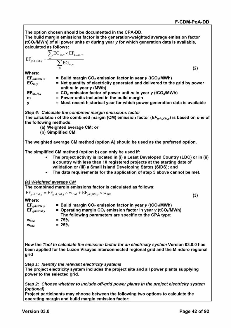
F-CDM-PoA-DD
Version 03.0 Page 42 of 92
The option chosen should be documented in the CPA-DD. The build margin emissions factor is the generation-weighted average emission factor (tCO2/MWh) of all power units m during year y for which generation data is available, calculated as follows:
∑∑ ×
=
mym,
my,m,ELy,m
yBM,grid, EG
EFGEEF
(2) Where: EFgrid,BM,y = Build margin CO2 emission factor in year y (tCO2/MWh) EGm,y = Net quantity of electricity generated and delivered to the grid by power
unit m in year y (MWh) EFEL,m,y = CO2 emission factor of power unit m in year y (tCO2/MWh) m = Power units included in the build margin y = Most recent historical year for which power generation data is available
Step 6: Calculate the combined margin emissions factor The calculation of the combined margin (CM) emission factor (EFgrid,CM,y) is based on one of the following methods:
(a) Weighted average CM; or (b) Simplified CM.
The weighted average CM method (option A) should be used as the preferred option. The simplified CM method (option b) can only be used if:
• The project activity is located in (i) a Least Developed Country (LDC) or in (ii) a country with less than 10 registered projects at the starting date of validation or (iii) a Small Island Developing States (SIDS); and
• The data requirements for the application of step 5 above cannot be met. (a) Weighted average CM The combined margin emissions factor is calculated as follows:
BMyBM,grid,OMyOM,grid,yCM,grid, wEFwEFEF ×+×= (3) Where: EFgrid,BM,y = Build margin CO2 emission factor in year y (tCO2/MWh) EFgrid,OM,y = Operating margin CO2 emission factor in year y (tCO2/MWh)
The following parameters are specific to the CPA type: wOM = 75% wBM = 25%
How the Tool to calculate the emission factor for an electricity system Version 03.0.0 has been applied for the Luzon Visayas interconnected regional grid and the Mindoro regional grid Step 1: Identify the relevant electricity systems The project electricity system includes the project site and all power plants supplying power to the selected grid. Step 2: Choose whether to include off-grid power plants in the project electricity system (optional) Project participants may choose between the following two options to calculate the operating margin and build margin emission factor:
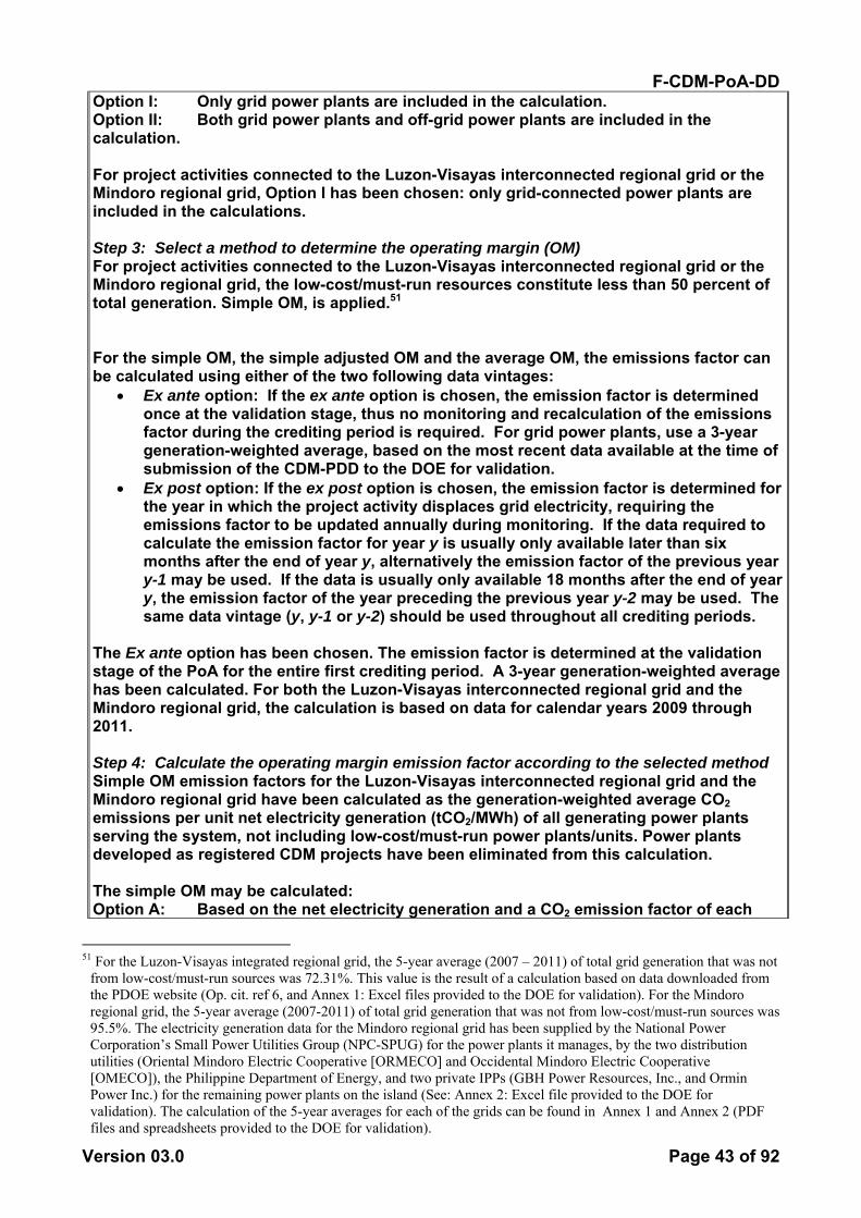
F-CDM-PoA-DD
Version 03.0 Page 43 of 92
Option I: Only grid power plants are included in the calculation. Option II: Both grid power plants and off-grid power plants are included in the calculation. For project activities connected to the Luzon-Visayas interconnected regional grid or the Mindoro regional grid, Option I has been chosen: only grid-connected power plants are included in the calculations. Step 3: Select a method to determine the operating margin (OM) For project activities connected to the Luzon-Visayas interconnected regional grid or the Mindoro regional grid, the low-cost/must-run resources constitute less than 50 percent of total generation. Simple OM, is applied.51 For the simple OM, the simple adjusted OM and the average OM, the emissions factor can be calculated using either of the two following data vintages:
• Ex ante option: If the ex ante option is chosen, the emission factor is determined once at the validation stage, thus no monitoring and recalculation of the emissions factor during the crediting period is required. For grid power plants, use a 3-year generation-weighted average, based on the most recent data available at the time of submission of the CDM-PDD to the DOE for validation.
• Ex post option: If the ex post option is chosen, the emission factor is determined for the year in which the project activity displaces grid electricity, requiring the emissions factor to be updated annually during monitoring. If the data required to calculate the emission factor for year y is usually only available later than six months after the end of year y, alternatively the emission factor of the previous year y-1 may be used. If the data is usually only available 18 months after the end of year y, the emission factor of the year preceding the previous year y-2 may be used. The same data vintage (y, y-1 or y-2) should be used throughout all crediting periods.
The Ex ante option has been chosen. The emission factor is determined at the validation stage of the PoA for the entire first crediting period. A 3-year generation-weighted average has been calculated. For both the Luzon-Visayas interconnected regional grid and the Mindoro regional grid, the calculation is based on data for calendar years 2009 through 2011. Step 4: Calculate the operating margin emission factor according to the selected method Simple OM emission factors for the Luzon-Visayas interconnected regional grid and the Mindoro regional grid have been calculated as the generation-weighted average CO2 emissions per unit net electricity generation (tCO2/MWh) of all generating power plants serving the system, not including low-cost/must-run power plants/units. Power plants developed as registered CDM projects have been eliminated from this calculation. The simple OM may be calculated: Option A: Based on the net electricity generation and a CO2 emission factor of each
51 For the Luzon-Visayas integrated regional grid, the 5-year average (2007 – 2011) of total grid generation that was not
from low-cost/must-run sources was 72.31%. This value is the result of a calculation based on data downloaded from the PDOE website (Op. cit. ref 6, and Annex 1: Excel files provided to the DOE for validation). For the Mindoro regional grid, the 5-year average (2007-2011) of total grid generation that was not from low-cost/must-run sources was 95.5%. The electricity generation data for the Mindoro regional grid has been supplied by the National Power Corporation’s Small Power Utilities Group (NPC-SPUG) for the power plants it manages, by the two distribution utilities (Oriental Mindoro Electric Cooperative [ORMECO] and Occidental Mindoro Electric Cooperative [OMECO]), the Philippine Department of Energy, and two private IPPs (GBH Power Resources, Inc., and Ormin Power Inc.) for the remaining power plants on the island (See: Annex 2: Excel file provided to the DOE for validation). The calculation of the 5-year averages for each of the grids can be found in Annex 1 and Annex 2 (PDF files and spreadsheets provided to the DOE for validation).
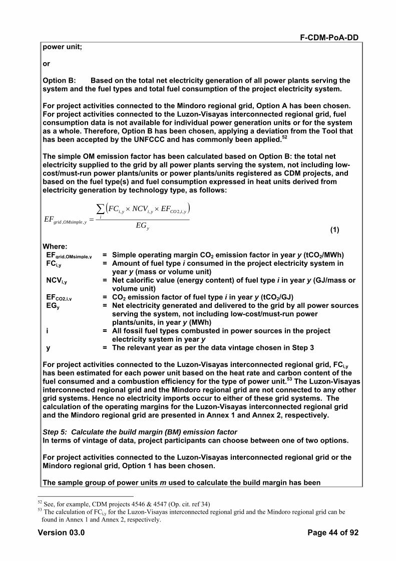
F-CDM-PoA-DD
Version 03.0 Page 44 of 92
power unit; or Option B: Based on the total net electricity generation of all power plants serving the system and the fuel types and total fuel consumption of the project electricity system. For project activities connected to the Mindoro regional grid, Option A has been chosen. For project activities connected to the Luzon-Visayas interconnected regional grid, fuel consumption data is not available for individual power generation units or for the system as a whole. Therefore, Option B has been chosen, applying a deviation from the Tool that has been accepted by the UNFCCC and has commonly been applied.52 The simple OM emission factor has been calculated based on Option B: the total net electricity supplied to the grid by all power plants serving the system, not including low-cost/must-run power plants/units or power plants/units registered as CDM projects, and based on the fuel type(s) and fuel consumption expressed in heat units derived from electricity generation by technology type, as follows:
( )y
iyiCOyiyi
yOMsimplegrid EG
EFNCVFCEF
∑ ××=
,,2,,
,,
(1) Where: EFgrid,OMsimple,y = Simple operating margin CO2 emission factor in year y (tCO2/MWh) FCi,y = Amount of fuel type i consumed in the project electricity system in
year y (mass or volume unit) NCVi,y = Net calorific value (energy content) of fuel type i in year y (GJ/mass or
volume unit) EFCO2,i,y = CO2 emission factor of fuel type i in year y (tCO2/GJ) EGy = Net electricity generated and delivered to the grid by all power sources
serving the system, not including low-cost/must-run power plants/units, in year y (MWh)
i = All fossil fuel types combusted in power sources in the project electricity system in year y
y = The relevant year as per the data vintage chosen in Step 3 For project activities connected to the Luzon-Visayas interconnected regional grid, FCi,y has been estimated for each power unit based on the heat rate and carbon content of the fuel consumed and a combustion efficiency for the type of power unit.53 The Luzon-Visayas interconnected regional grid and the Mindoro regional grid are not connected to any other grid systems. Hence no electricity imports occur to either of these grid systems. The calculation of the operating margins for the Luzon-Visayas interconnected regional grid and the Mindoro regional grid are presented in Annex 1 and Annex 2, respectively. Step 5: Calculate the build margin (BM) emission factor In terms of vintage of data, project participants can choose between one of two options. For project activities connected to the Luzon-Visayas interconnected regional grid or the Mindoro regional grid, Option 1 has been chosen. The sample group of power units m used to calculate the build margin has been
52 See, for example, CDM projects 4546 & 4547 (Op. cit. ref 34) 53 The calculation of FCi,y for the Luzon-Visayas interconnected regional grid and the Mindoro regional grid can be
found in Annex 1 and Annex 2, respectively.
F-CDM-PoA-DD
Version 03.0 Page 45 of 92
determined as follows:
(a) Identify the set of five power units, excluding power units registered as CDM project activities, that started to supply electricity to the grid most recently (SET5-units) and determine their annual electricity generation (AEGSET-5-units, in MWh);
(b) Determine the annual electricity generation of the project electricity system, excluding power units registered as CDM project activities (AEGtotal, in MWh). Identify the set of power units, excluding power units registered as CDM project activities, that started to supply electricity to the grid most recently and that comprise 20% of AEGtotal (if 20% falls on part of the generation of a unit, the generation of that unit is fully included in the calculation) (SET≥20%) and determine their annual electricity generation (AEGSET-≥20%, in MWh);
(c) From SET5-units and SET≥20% select the set of power units that comprises the larger annual electricity generation (SETsample);
Identify the date when the power units in SETsample started to supply electricity to the grid. If none of the power units in SETsample started to supply electricity to the grid more than 10 years ago, then use SETsample to calculate the build margin. Ignore steps (d), (e) and (f). The determination of the build margin sample groups for the Luzon-Visayas interconnected regional grid and the Mindoro regional grid are presented in Annex 1 and Annex 2, respectively. SET≥20% has been selected as SETsample for both the Luzon-Visayas and Mindoro grids. None of the power units in SETsample in either of these two grid systems started to supply electricity to the grid more than 10 years ago. Hence, SETsample has been used to calculate the build margin emissions factor. The build margin emissions factor has been calculated as the generation-weighted average emission factor (tCO2/MWh) of all power units m during year y. Using the most recent available data, year y is 2011 for both the Luzon-Visayas interconnected regional grid and the Mindoro regional grid. The calculation of the build margin emission factors for the Luzon-Visayas interconnected regional grid and the Mindoro regional grid are presented in Annex 1 and Annex 2, respectively. Step 6: Calculate the combined margin emissions factor The calculation of the combined margin (CM) emission factor (EFgrid,CM,y) is based on one of the following methods:
(c) Weighted average CM; or (d) Simplified CM.
The weighted average CM method (option A) should be used as the preferred option. The simplified CM method (option b) can only be used if:
• The project activity is located in a Least Developed Country (LDC) or in a country with less than 10 registered projects at the starting date of validation; and
• The data requirements for the application of step 5 above cannot be met. For project activities connected to the Luzon-Visayas interconnected regional grid or the Mindoro regional grid, option (a), the weighted average CM, has been chosen. (a) Weighted average CM The combined margin emissions factor is calculated ex ante as follows:
BMyBM,grid,OMyOM,grid,yCM,grid, wEFwEFEF ×+×= (3) Where:
F-CDM-PoA-DD
Version 03.0 Page 46 of 92
EFgrid,BM,y = Build margin CO2 emission factor in year y (tCO2/MWh) EFgrid,OM,y = Operating margin CO2 emission factor in year y (tCO2/MWh) wOM = Weighting of operating margin emissions factor (%) wBM = Weighting of operating margin emissions factor (%)
The respective weights – WOM and WBM – for each CPA technology type, as specified in the Tool to calculate the emission factor for an electricity system, Version 03.0.0 have been applied. The grid emission factors for the Luzon-Visayas interconnected regional grid and the Mindoro regional grid shall be monitored at the PoA level in accordance with the monitoring methodology published in the “Tool to calculate the emission factor for an electricity system” (Version 03.0.0). The grid emission factors for all other grid systems shall be monitored at the CPA level in accordance with the monitoring methodology published in the “Tool to calculate the emission factor for an electricity system” (Version 03.0.0). Leakage As per ACM0002 version 13.0.0 no leakage emissions are considered. Emission reductions: As project emissions and leakage are zero, emission reductions for a CPA shall be calculated as follows:
(11) Where:
Emission reductions in year y (t CO2e)
Baseline Emissions in year y (t CO2)
Estimation of emissions reductions prior to validation Project participants should prepare as part of the CPA-DD an estimate of likely emission reductions for the proposed crediting period. This estimate should, in principle, employ the same methodology as selected above. Changes required for methodology implementation in 2nd and 3rd crediting periods At the start of the second and third crediting period project proponents have to address two issues: • Assess the continued validity of the baseline; and • Update the baseline. In assessing the continued validity of the baseline, a change in the relevant national and/or sectoral regulations between two crediting periods has to be examined by each CPA at the start of the new crediting period. If at the start of the project activity, the project activity was not mandated by regulations, but at the start of the second or third crediting period regulations are in place that enforce the practice or norms or technologies that are used by the project activity, the new regulation (formulated after the registration of the project activity) has to be examined to determine if it applies to existing plants or not. If the new regulation applies to existing CDM project activities, the baseline has to be reviewed and, if the regulation is binding, the baseline for the project activity should take this into account. This assessment will be undertaken by the verifying DOE.
yER
yBE
y y BEER =

F-CDM-PoA-DD
Version 03.0 Page 47 of 92
For updating the baseline at the start of the second and third crediting period, new data available will be used to revise the baseline scenario and emissions. Project participants shall assess and incorporate the impact of new regulations on baseline emissions. Requirements for updating of ex ante grid emission factors at the start of the second and third crediting periods are provided in the Tool to calculate the emission factor for an electricity system (Version 03.0.0). The operating margin emission factor should be updated at the beginning of each crediting period. The build margin emission factor should be updated for the second crediting period based on the most recent information available on units already built at the time of submission of the request for renewal of the crediting period to the DOE. For the third crediting period, the build margin emission factor calculated for the second crediting period should be used. Ex ante calculations of grid emission factors do not require monitoring the emission factor during the crediting period.
B.6.2. Data and parameters that are to be reported ex-ante >> Fixed parameters: The following parameters are fixed for all CPAs included during the first 7 years of the PoA crediting period and for the respective first 7-year crediting period of these CPAs. These parameters are to be updated at the PoA level at the start of the second and third crediting periods of the PoA: For CPAs connected to the Luzon-Visayas interconnected regional grid or the Mindoro regional grid, sources and values have been provided here for the parameters associated with calculations of the grid emission factor. For CPAs connected to other grid systems, the sources and values for these parameters are to be determined at the CPA level.
(Copy this table for each data and parameter.)
Data / Parameter: EFCO2,i,y and EFCO2,m,i,y Data unit: kgCO2/TJ Description: Emission factor of fuel type i used in power unit m in year y Source of data: IPCC default values at the lower limit of the uncertainty at a
95% confidence interval as provided in Table 1.4 of Chapter 1 of Vol. 2 (Energy) of the 2006 IPCC Guidelines on National GHG Inventories.
Value(s) applied: Coal (Anthracite) 94,600; Diesel Oil 72,600; Residual Fuel Oil 75,500; Natural Gas 54,300
Choice of data or Measurement methods and procedures:
Reliable data for the Philippines is not available. The IPCC default values have been applied as per the Tool to calculate the emission factor for an electricity system Version 03.0.0
Purpose of data Calculation of baseline emissions Additional comment:
None
The following fixed parameter associated with calculations of the grid emission factor is specific to the CPA type. For CPA type 1:
Data / Parameter: EFgrid,CM Data unit: tCO2/MWh
F-CDM-PoA-DD
Version 03.0 Page 48 of 92
Description: CO2 emission factors for electricity displaced from the relevant regional grid.
Source of data: Calculated, based on electricity generation data. Value(s) applied: Values are grid specific. PoA-level calculation results: Choice of data or Measurement methods and procedures:
0.562 for the Luzon-Visayas interconnected regional grid 0.732 for the Mindoro regional grid.
Purpose of data Calculation of baseline emissions. Additional comment:
This parameter is to be calculated for the relevant grid system to which a given CPA is connected. For CPAs connected to the Luzon-Visayas interconnected regional grid and the Mindoro regional grid, this parameter has been calculated ex ante and established at the PoA level, in accordance with the “Tool to calculate the emission factor for an electricity system” (Version 03.0.0).
Data / Parameter: EGm,y Data unit: MWh Description: Net electricity generated by power plant/unit m in year y Source of data: Sources are grid specific. For data specific to the Luzon
Visayas interconnected regional grid the source is PDOE. Data specific to the Mindoro grid has been supplied by the National Power Corporation’s Small Power Utilities Group (NPC-SPUG) for the power plants it manages, by the two distribution utilities (Oriental Mindoro Electric Cooperative [ORMECO] and Occidental Mindoro Electric Cooperative [OMECO]), the Philippine department of Energy, and two private IPPs (GBH Power Resources, Inc., and Ormin Power Inc.) for the remaining power plants on the island. (Op. cit. ref 6, Excel files provided to the DOE for validation).
Value(s) applied: Values are grid specific. For data specific to the Luzon Visayas interconnected regional grid or Mindoro regional grid, see Annex 1 and Annex 2
Choice of data or Measurement methods and procedures:
The Philippines Department of Energy is the national official source of net electricity generation data for the Luzon-Visayas interconnected regional grid.
Purpose of data There is no official central source for electricity generation data for the Mindoro regional grid. The National Power Corporation’s Small Power Utilities Group (NPC-SPUG) is the only comprehensive source of data for the power plants it manages. To complete the database it was necessary to collect data from the two distribution utilities (Oriental Mindoro Electric Cooperative [ORMECO] and Occidental Mindoro Electric Cooperative [OMECO]), the Philippine department of Energy, and two private IPPs (GBH Power Resources, Inc., and Ormin Power Inc.) for the remaining power plants on the island
Additional comment:
Calculation of baseline emissions
F-CDM-PoA-DD
Version 03.0 Page 49 of 92
Data / Parameter: EFEL,m,y Data unit: tCO2/MWh Description: Power unit emission factor Source of data: Calculated Value(s) applied: Values are grid specific. For calculations performed for the
Luzon Visayas interconnected regional grid and the Mindoro regional grid, see Annex 1 and Annex 2
Choice of data or Measurement methods and procedures:
This parameter has been calculated ex ante for the Luzon-Visayas interconnected regional grid and the Mindoro regional grid, in accordance with the “Tool to calculate the emission factor for an electricity system” (Version 03.0.0).
Purpose of data Calculation of baseline emissions Additional comment:
None
Data / Parameter: FCi,m,y Data unit: Mass or volume unit Description: Amount of fossil fuel type i consumed by power plant/unit m in
year y Source of data: Utility or government records or official publications Value(s) applied: Values are grid specific. For calculations performed for the
Luzon Visayas interconnected regional grid and the Mindoro regional grid, see Annex 1 and Annex 2
Choice of data or Measurement methods and procedures:
In accordance with the “Tool to calculate the emission factor for an electricity system” (Version 03.0.0)
Purpose of data Calculation of baseline emissions Additional comment:
None
Data / Parameter: NCVi,y Data unit: GJ/mass or volume unit Description: Net calorific value (energy content) of fossil fuel type i in year y
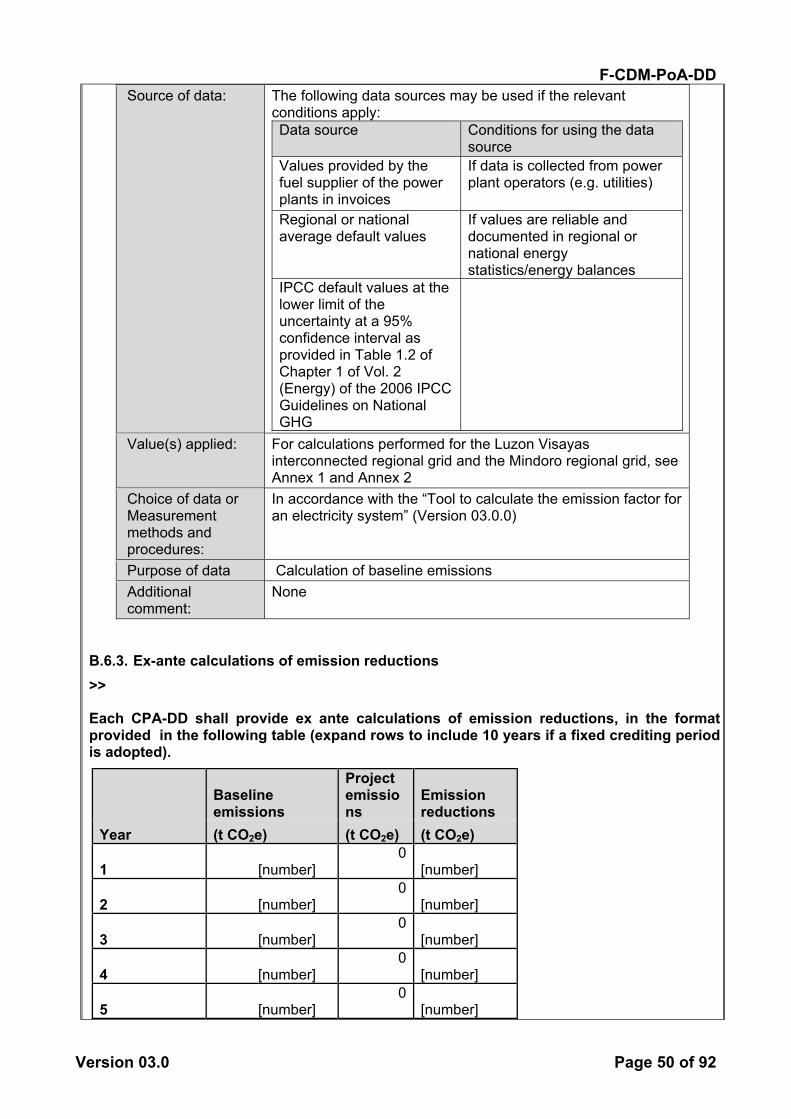
F-CDM-PoA-DD
Version 03.0 Page 50 of 92
Source of data: The following data sources may be used if the relevant conditions apply: Data source Conditions for using the data
source Values provided by the fuel supplier of the power plants in invoices
If data is collected from power plant operators (e.g. utilities)
Regional or national average default values
If values are reliable and documented in regional or national energy statistics/energy balances
IPCC default values at the lower limit of the uncertainty at a 95% confidence interval as provided in Table 1.2 of Chapter 1 of Vol. 2 (Energy) of the 2006 IPCC Guidelines on National GHG
Value(s) applied: For calculations performed for the Luzon Visayas interconnected regional grid and the Mindoro regional grid, see Annex 1 and Annex 2
Choice of data or Measurement methods and procedures:
In accordance with the “Tool to calculate the emission factor for an electricity system” (Version 03.0.0)
Purpose of data Calculation of baseline emissions Additional comment:
None
B.6.3. Ex-ante calculations of emission reductions >>
Each CPA-DD shall provide ex ante calculations of emission reductions, in the format provided in the following table (expand rows to include 10 years if a fixed crediting period is adopted).
Year
Baseline emissions
Project emissions
Emission reductions
(t CO2e) (t CO2e) (t CO2e)
1 [number] 0
[number]
2 [number] 0
[number]
3 [number] 0
[number]
4 [number] 0
[number]
5 [number] 0
[number]

F-CDM-PoA-DD
Version 03.0 Page 51 of 92
6 [number] 0
[number]
7 [number] 0
[number] Total [number] 0
[number] Total number of crediting years
[number]
Annual [number] 0
[number] average over
the crediting period
B.7. Application of the monitoring methodology and description of the monitoring plan
B.7.1. Data and parameters to be monitored by each generic CPA
(Copy this table for each data and parameter).
Data / Parameter: EGfacility,y Data unit: MWh/yr Description: Quantity of net electricity generation supplied by the project
plant/unit to the grid in year y Source of data: Electricity meter(s) Value(s) applied [number] Measurement methods and procedures:
The following parameters shall be measured: (i) The quantity of electricity supplied by the project plant/unit to the grid; and (ii) The quantity of electricity delivered to the project plant/unit from the grid In cases where electricity is delivered to the project from the grid, EGfacility,y shall be equal (i) minus (ii). Electricity meters The meter shall be installed at the point of connection to the grid as agreed with the grid operator. A high level of accuracy of the measurements will be achieved through the use of high-precision equipment calibrated and tested according to recognized standards and agreed with the grid operator. NOTE: The electricity meter owned by the grid operator is managed and maintained under the sole responsibility of the grid operator and according to their internal standards. Therefore, it is not under the control of the CPA.
Monitoring frequency:
Continuous measurement and at least monthly recording
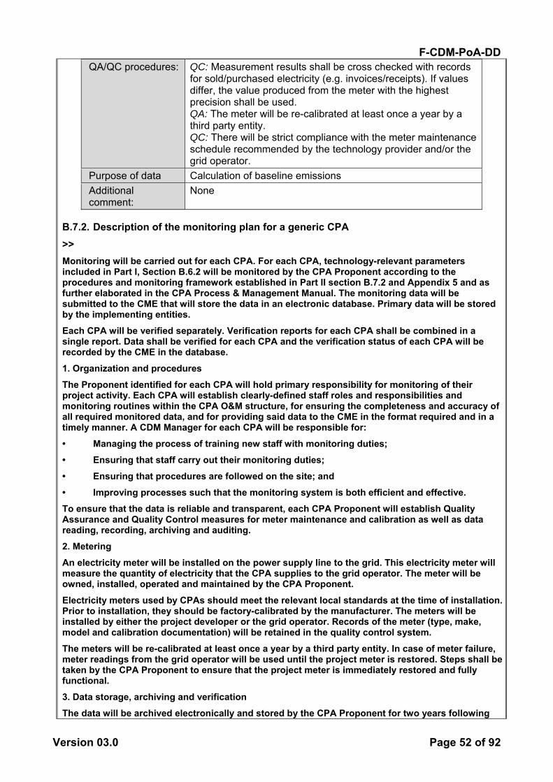
F-CDM-PoA-DD
Version 03.0 Page 52 of 92
QA/QC procedures: QC: Measurement results shall be cross checked with records for sold/purchased electricity (e.g. invoices/receipts). If values differ, the value produced from the meter with the highest precision shall be used. QA: The meter will be re-calibrated at least once a year by a third party entity. QC: There will be strict compliance with the meter maintenance schedule recommended by the technology provider and/or the grid operator.
Purpose of data Calculation of baseline emissions Additional comment:
None
B.7.2. Description of the monitoring plan for a generic CPA >> Monitoring will be carried out for each CPA. For each CPA, technology-relevant parameters included in Part I, Section B.6.2 will be monitored by the CPA Proponent according to the procedures and monitoring framework established in Part II section B.7.2 and Appendix 5 and as further elaborated in the CPA Process & Management Manual. The monitoring data will be submitted to the CME that will store the data in an electronic database. Primary data will be stored by the implementing entities.
Each CPA will be verified separately. Verification reports for each CPA shall be combined in a single report. Data shall be verified for each CPA and the verification status of each CPA will be recorded by the CME in the database.
1. Organization and procedures
The Proponent identified for each CPA will hold primary responsibility for monitoring of their project activity. Each CPA will establish clearly-defined staff roles and responsibilities and monitoring routines within the CPA O&M structure, for ensuring the completeness and accuracy of all required monitored data, and for providing said data to the CME in the format required and in a timely manner. A CDM Manager for each CPA will be responsible for:
• Managing the process of training new staff with monitoring duties; • Ensuring that staff carry out their monitoring duties;
• Ensuring that procedures are followed on the site; and
• Improving processes such that the monitoring system is both efficient and effective. To ensure that the data is reliable and transparent, each CPA Proponent will establish Quality Assurance and Quality Control measures for meter maintenance and calibration as well as data reading, recording, archiving and auditing. 2. Metering
An electricity meter will be installed on the power supply line to the grid. This electricity meter will measure the quantity of electricity that the CPA supplies to the grid operator. The meter will be owned, installed, operated and maintained by the CPA Proponent.
Electricity meters used by CPAs should meet the relevant local standards at the time of installation. Prior to installation, they should be factory-calibrated by the manufacturer. The meters will be installed by either the project developer or the grid operator. Records of the meter (type, make, model and calibration documentation) will be retained in the quality control system.
The meters will be re-calibrated at least once a year by a third party entity. In case of meter failure, meter readings from the grid operator will be used until the project meter is restored. Steps shall be taken by the CPA Proponent to ensure that the project meter is immediately restored and fully functional.
3. Data storage, archiving and verification
The data will be archived electronically and stored by the CPA Proponent for two years following

F-CDM-PoA-DD
Version 03.0 Page 53 of 92
the end of the CPA crediting period to which it applies. The CPA Proponent will also provide the CME with copies of calibration certificates as well as receipts from sales to the relevant grid operator. The CME has developed and will maintain an electronic data storage and retrieval system with unique identifiers for each CPA, constituting individual records within the system. The data maintained in this system will include the metered data quantifying the electricity supplied to the grid. The CME will also archive written documentation of the CPAs (such as maps, diagrams, permits/licenses, and the feasibility study). The CME will be responsible for providing the verifying DOE with all data required from the individual CPAs.
F-CDM-PoA-DD
Version 03.0 Page 54 of 92
PART II. Generic component project activity (CPA)
For CPA type 2 (run-of-river hydro)
SECTION A. General description of a generic CPA
A.1. Purpose and general description of generic CPAs >> The generic purpose of CPAs included in this PoA is to support the development of renewable energy projects that feed electric power into a grid in the Host Country. In general, the PoA enables developers of such CPAs to overcome financial and other barriers to developing and implementing their projects, by harnessing the financial support made available through the sale of carbon credits.
SECTION B. Application of a baseline and monitoring methodology
B.1. Reference of the approved baseline and monitoring methodology(ies) selected >> Please see Part II, for CPA type 1, Section B.1, which also applies here.
B.2. Application of methodology(ies) >> Compliance with the applicability conditions in ACM0002 Version 13.0.0 and all associated Tools is included as an eligibility requirement for all CPAs applying for inclusion in this PoA. Table 2. Relevance of ACM0002 to the proposed PoA Applicability Condition from the Meth Relevance to Proposed PoA This methodology is applicable to grid-connected renewable power generation project activities that: (a) install a new power plant at a site where no renewable power plant was operated prior to the implementation of the project activity (greenfield plant); (b) involve a capacity addition; (c) involve a retrofit of (an) existing plant(s); or (d) involve a replacement of (an) existing plant(s).
The proposed PoA is applicable to project activities that install a new power plant at a site where there was no renewable energy power plant operating prior to the implementation of the project activity (Greenfield plant). The proposed PoA is not applicable to project activities that involve capacity additions, retrofits of existing plants, or replacements of existing plants. Adherence to this condition shall be confirmed for CPAs through supporting studies or documentation such as feasibility studies and/or business plans.
F-CDM-PoA-DD
Version 03.0 Page 55 of 92
The methodology is applicable under the following conditions: • The project activity is the installation,
capacity addition, retrofit or replacement of a power plant/unit of one of the following types: hydro power plant/unit (either with a run-of-river reservoir or an accumulation reservoir), wind power plant/unit, geothermal power plant/unit, solar power plant/unit, wave power plant/unit or tidal power plant/unit;
• In the case of capacity additions, retrofits or replacements (except for wind, solar, wave or tidal power capacity addition projects which use Option 2 on page 10 of version 13.0.0 of the methodology to calculate the parameter EGPJ,y): the existing plant started commercial operation prior to the start of a minimum historical reference period of five years, used for the calculation of baseline emissions and defined in the baseline emission section, and no capacity expansion or retrofit of the plant has been undertaken between the start of this minimum historical reference period and the implementation of the project activity.;
The proposed PoA is applicable to installation of greenfield run-of-river hydro, wind, geothermal, solar PV, wave and tidal power plants/units supplying electricity to a grid. The PoA is not applicable to solar thermal projects. The PoA is not applicable to hydropower projects that create new accumulation reservoirs or increase the volume of an existing reservoir. Adherence to this condition shall be confirmed through supporting studies or documentation such as feasibility studies and/or business plans.
In case of hydro power plants: • One of the following conditions must apply:
o The project activity is implemented in an existing single or multiple reservoirs, with no change in the volume of any of the reservoirs; or
o The project activity is implemented in an existing single or multiple reservoirs, where the volume of any of the reservoirs is increased and the power density of each reservoir, as per the definitions given in the project emissions section, is greater than 4 W/m2; or
o The project activity results in new single or multiple reservoirs and the power density of each reservoir, as per the definitions given in the project emissions section, is greater than 4 W/m2.
This PoA is only applicable to greenfield project activities. New and existing accumulation reservoirs are not allowed under this PoA. Adherence to this condition shall be confirmed for CPAs through supporting studies or documentation such as feasibility studies and/or business plans.
In case of hydro power plants using multiple reservoirs where the power density of any of the reservoirs is lower than 4 W/m2 all of the following conditions must apply:
• The power density calculated for the entire project activity using equation 5 is greater than 4 W/m2;
• Multiple reservoirs and hydro power plants located at the same river and where are designed together to function as an integrated project that collectively constitute the generation capacity of the
New and existing accumulation reservoirs are not allowed under this PoA. Adherence to this condition shall be confirmed for CPAs through supporting studies or documentation such as feasibility studies and/or business plans.
F-CDM-PoA-DD
Version 03.0 Page 56 of 92
combined power plant; • Water flow between multiple reservoirs is
not used by any other hydropower unit which is not a part of the project activity;
• Total installed capacity of the power units, which are driven using water from the reservoirs with a power density lower than 4 W/m2, is lower than 15 MW;
• Total installed capacity of the power units, which are driven using water from reservoirs with a power density lower than 4 W/m2, is less than 10% of the total installed capacity of the project activity from multiple reservoirs.
The methodology is not applicable to the following: • Project activities that involve switching from
fossil fuels to renewable energy sources at the site of the project activity, since in this case the baseline may be the continued use of fossil fuels at the site;
• Biomass fired power plants; • A hydro power plant that results in the
creation of a new single reservoir or in the increase in an existing single reservoir where the power density of the reservoir is less than 4 W/m2.
• As this CPA type relates to greenfield run-of-river hydro projects, the first two bullets under this condition are met.
• Hydropower plants that create new accumulation reservoirs or increase the volume of existing reservoirs are excluded from this PoA.
Adherence to this condition shall be confirmed for CPAs through supporting studies or documentation such as feasibility studies and/or business plans.
In the case of retrofits, replacements, or capacity additions, this methodology is only applicable if the most plausible baseline scenario, as a result of the identification of baseline scenario, is “the continuation of the current situation, i.e. to use the power generation equipment that was already in use prior to the implementation of the project activity and undertaking business as usual maintenance”.
The proposed PoA is only applicable to greenfield project activities. Therefore, this applicability condition is not relevant.
In addition, the applicability conditions included in the tools referred to above apply.54 Relevant tools:
• “Tool to calculate the emission factor for an electricity system”;
• “Tool for the demonstration and assessment of additionality”;
• “Combined tool to identify the baseline scenario and demonstrate additionality”;
• “Tool to calculate project or leakage CO2 emissions from fossil fuel combustion”.
The proposed PoA incorporates this requirement in its applicability conditions. As such, the following applicability conditions apply for run-of-river hydro CPAs: From the Tool to calculate the emission factor for an electricity system, version 03.0.0:
• “This tool may be applied to estimate the OM, BM and/or CM when calculating baseline emissions for a project activity that substitutes grid electricity, i.e. where a project activity supplies electricity to a grid or a project activity that results in savings
54 The condition in the “Combined tool to identify the baseline scenario and demonstrate additionality” that all potential
alternative scenarios to the proposed project activity must be available options to project participants does not apply to this methodology, as this methodology only refers to some steps of this tool.
F-CDM-PoA-DD
Version 03.0 Page 57 of 92
of electricity that would have been provided by the grid (e.g. demand-side energy efficiency projects).”
This PoA is only applicable to project activities that supply electricity to a grid. Hence all CPAs under this PoA adhere to this condition.
• “In case of CDM projects the tool is not applicable if the project electricity system is located partially or totally in an Annex I country.”
This PoA is only applicable to CDM project activities. Hence all CPAs under this PoA adhere to this condition. From the Tool for the demonstration and assessment of additionality, version 7.0.0:
• “Project activities that apply this tool in context of approved consolidated methodology ACM0002, only need to identify that there is at least one credible and feasible alternative that would be more attractive than the proposed project activity.”
This PoA applies ACM0002. Therefore, CPAs under this PoA need only identify one credible and feasible alternative that would be more attractive than the proposed project activity. This applicability condition shall be reflected in the additionality assessment for each CPA.
B.3. Sources and GHGs For the emissions sources included in or excluded from the project boundary please see Part II, for CPA type 1, Section B.3, Table 3, which also applies here.

F-CDM-PoA-DD
Version 03.0 Page 58 of 92
Figure 4: Sample flow diagram (run-of-river hydro)
B.4. Description of baseline scenario >> Please see Part II, for CPA type 1, Section B.4, which also applies here.
B.5. Demonstration of eligibility for a generic CPA >> Confirming compliance with the PoA eligibility criteria: Please see Part II, for CPA type 1, Section B.5., under the heading “Confirming compliance with the PoA eligibility criteria,” for EC#s 1-13 of which also apply here. EC# 7 is further elaborated below with respect to conditions that are specific to this CPA type. Table 4. Eligibility compliance check (run-of-river hydro CPAs)
EC# Item Means of demonstrating compliance
Compliance check
7 CPAs electing to perform an investment analysis shall conform to the a) technical and b) economic parameters established under each CPA type
a) CPA developers shall demonstrate that their project falls within the allowable ranges for load factors of the technology to be applied as specified under each generic CPA type in Part II. The load factor range for run-of-river hydropower projects in the Philippines55 is 40-50%.
[Refer to relevant supporting documentation]
55 See table 1 & associated notes
F-CDM-PoA-DD
Version 03.0 Page 59 of 92
b) Further they shall utilize the key items of capital expenditure that are specified under each generic CPA type in Part II in preparing their analysis The capital expenditures56 for run-of-river hydroelectric projects in the Philippines shall include:
i. Equipment cost (turbines, generators and auxiliary equipment), transportation from country of origin to project site, and balance of plant (engineering works) range US$2,189-2,599/ kW;
ii. VAT on imported goods 30% of 12%;
iii. switchyard & transformers ≤US$500,000;
iv. transmission lines to grid range US$69,700-84,000/ km;
v. service/ access road ≤US$20,000/ km;
vi. construction contingency 7.5% of total project cost;
vii. Initial working capital 5% of EPC;
viii. development costs (e.g. land, permits) 2.5% of EPC (i-vii).
Confirming additionality at the CPA level: Please see Part II, for CPA type 1, Section B.5 under the heading “Confirming additionality at the CPA level,” which also applies here. Apply the framework established in Part I, Section B.1, Procedure 2, Step 3 using the general and the wind power specific parameters as defined in eligibility criterion #7 above as follows:
• Input parameters (duly documented as to source) o General (year of assumptions & relevant exchange rates) o Run-of-river hydropower specific capital expenditure items or CapEx for:
turbines, generators and auxiliary equipment; transportation from country of
56 See table 1 & associated notes
F-CDM-PoA-DD
Version 03.0 Page 60 of 92
origin to the project site; balance of plant/ engineering cost; switch yard & transformer costs conforming to the values defined under EC#7 above;
o General CapEx for: transmission line distance and unit cost; access road distance and unit cost; development related costs; contingency; tax on imported goods if relevant; and initial working capital conforming to the values defined under EC#7 above;
o Operation and maintenance costs or OpEx (cost of spare parts and maintenance equipment, staff costs and yearly O&M cost);
o Revenues (installed capacity, net capacity factor, operating hours/ year, electricity tariff and grid emission factor);
The above input values shall be used to derive:
• Total project costs or TPC (the sum of CapEx and OpEx) for each year of the project cycle and CER crediting period;
• Yearly project revenues; • A pre-tax net cash flow; and finally • The pre-tax project IRR derived from all net cash flows.
A sensitivity analysis shall be performed as follows unless this is not deemed appropriate in the context of the specific project circumstances:
• Plus and minus 10% of the revenues from power sales; • Plus and minus 10% of the CapEx; • Plus and minus 10% of the OpEx/ O&M; and • With CDM revenues.
The pre-tax project IRR shall be compared with the benchmark established in Part I, Section B.1, Procedure 2, Step 3, Sub-step 3b. Common Practice Analysis The following common practice analysis has been carried out in accordance with the Guidelines on Common Practice version 2.0. The details of each step can be found in the guideline and are not repeated here. Step 1: calculate applicable capacity or output range as +/-50% of the total design capacity or output of the proposed project activity. For hydropower, we have analyzed two applicable output ranges: small scale (≤15MW) and large scale (>15MW). Step 2: identify similar projects (both CDM and non-CDM) which fulfil all of the conditions presented in the Guideline: With the justification presented in Part I Section B.1, we have analyzed two geographical areas: the area connected to the Luzon-Visayas interconnected regional grid, and the area connected to the Mindanao regional grid. However, all of the large-scale hydro power capacity in the Philippines is connected to the Luzon-Visayas and Mindanao regional grids. Therefore, large-scale hydro is not common practice anywhere in the Philippines outside these regions. Small scale Luzon-Visayas: All of the small-scale plants connected to the Luzon-Visayas grid were built as non-commercially-viable investments, either by the government (pre-privatization) or local non-profit electricity cooperatives. Therefore, there are no small-scale hydropower plants that meet all of the criteria in Step 2. Small-scale Mindanao: There are three small-scale hydro plants, none of which were invested in on a commercial basis. Therefore, there are no small-scale hydropower plants that meet all of the criteria in Step 2.
F-CDM-PoA-DD
Version 03.0 Page 61 of 92
Large-scale Luzon-Visayas: There is 2,420MW of large-scale hydro power capacity connected to the Luzon-Visayas regional grid, none of which are commercial investments. Large-scale Mindanao: There is one large-scale hydro plant built on a commercial basis. Step 3: within the projects identified in Step 2, identify those that are neither registered CDM project activities, project activities submitted for registration, nor project activities undergoing validation. Note their number Nall. Small scale: There are no power plants that meet all of the criteria of Step 2 for either Luzon-Visayas or Mindanao. Large-scale Visayas: There are no power plants that meet all of the criteria of Step 2. Large scale Mindanao: The one large-scale hydropower plant is registered as a CDM activity. 57 Therefore, Nall = 0. As Step 3 results in no power plants for further analysis, commercial investments in hydropower plants of any size are not common practice in the regional grid systems in Luzon-Visayas or Mindanao. As there are no large-scale hydropower plants elsewhere in the country and Step 3 results in no large-scale power plants for further analysis in Luzon-Visayas or Mindanao, large-scale commercial hydropower investments are not common practice in any of the grid systems in the Philippines.
B.6. Estimation of emission reductions of a generic CPA
B.6.1, Explanation of methodological choices >> Please see Part II, for CPA type 1, Section B.6.1., which also applies here. Baseline emissions For projects performing combined margin calculations while determining a grid emission factor: (a) Weighted average CM The combined margin emissions factor is calculated as follows:
BMyBM,grid,OMyOM,grid,yCM,grid, wEFwEFEF ×+×= (3) Where: EFgrid,BM,y = Build margin CO2 emission factor in year y (tCO2/MWh) EFgrid,OM,y = Operating margin CO2 emission factor in year y (tCO2/MWh) wOM = 50% wBM = 50%
B.6.2. Data and parameters that are to be reported ex-ante >> Please see Part II, for CPA type 1, Section B.6.2., which also applies here. Fixed parameters: For CPAs connected to the Luzon-Visayas interconnected regional grid or the Mindoro regional grid, the following parameter associated with calculations of the grid emission factor is specific to the CPA type. For CPA type 2:
57 Hedcor Sibulan (CDM reference number 1620)

F-CDM-PoA-DD
Version 03.0 Page 62 of 92
(Copy this table for each data and parameter.)
Data / Parameter: EFgrid,CM
Data unit: tCO2/MWh Description: CO2 emission factors for electricity displaced from the relevant
regional grid. Source of data: Calculated, based on electricity generation data. Value(s) applied: Values are grid specific. PoA-level calculation results:
0.511 for the Luzon-Visayas interconnected regional grid. 0.761 for the Mindoro regional grid.
Choice of data or Measurement methods and procedures:
This parameter is to be calculated for the relevant grid system to which a given CPA is connected. For CPAs connected to the Luzon-Visayas interconnected regional grid and the Mindoro regional grid, this parameter has been calculated ex ante and established at the PoA level, in accordance with the “Tool to calculate the emission factor for an electricity system” (Version 03.0.0).
Purpose of data Calculation of baseline emissions Additional comment:
None
B.6.3. Ex-ante calculations of emission reductions >> Please see Part II, for CPA type 1, Section B.6.3., which also applies here.
B.7. Application of the monitoring methodology and description of the monitoring plan
B.7.1. Data and parameters to be monitored by each generic CPA
(Copy this table for each data and parameter).
Please see Part II, for CPA type 1, Section B.7.1., which also applies here.
B.7.2. Description of the monitoring plan for a generic CPA >> Please see Part II, for CPA type 1, Section B.7.2., which also applies here.

F-CDM-PoA-DD
Version 03.0 Page 63 of 92
PART II. Generic component project activity (CPA)
For CPA type 3 (solar PV)
SECTION A. General description of a generic CPA
A.1. Purpose and general description of generic CPAs >> The generic purpose of CPAs included in this PoA is to support the development of renewable energy projects that feed electric power into a grid in the Host Country. In general, the PoA enables developers of such CPAs to overcome financial and other barriers to developing and implementing their projects, by harnessing the financial support made available through the sale of carbon credits.
SECTION B. Application of a baseline and monitoring methodology
B.1. Reference of the approved baseline and monitoring methodology(ies) selected >> Please see Part II, for CPA type 1, Section B.1, which also applies here.
B.2. Application of methodology(ies) >> Please see Part II, for CPA type 1, Section B.2, which also applies here.
B.3. Sources and GHGs
For the emissions sources included in or excluded from the project boundary please see Part II, for CPA type 1, Section B.3, Table 3, which also applies here.
Figure 6: Sample flow diagram (solar PV)
F-CDM-PoA-DD
Version 03.0 Page 64 of 92
B.4. Description of baseline scenario >> Please see Part II, for CPA type 1, Section B.4., which also applies here.
B.5. Demonstration of eligibility for a generic CPA >> Confirming compliance with the PoA eligibility criteria: Please see Part II, for CPA type 1, Section B.5., under the heading “Confirming compliance with the PoA eligibility criteria,” for EC#s 1-13 of which also apply here. EC# 7 is further elaborated below with respect to conditions that are specific to this CPA type. Table 4. Eligibility compliance check (solar PV CPAs)
EC# Item Means of demonstrating compliance
Compliance check
7 CPAs electing to perform an investment analysis shall conform to the a) technical and b) economic parameters established under each CPA type
a) CPA developers shall demonstrate that their project falls within the allowable ranges for load factors of the technology to be applied as specified under each generic CPA type in Part II. The load factor range for solar PV projects in the Philippines58 is 20-24%. b) Further they shall utilize the key items of capital expenditure that are specified under each generic CPA type in Part II in preparing their analysis The capital expenditures for solar PV projects in the Philippines59 shall include:
i. Equipment cost (photovoltaic panels and auxiliary equipment), transportation from country of origin to project site, and balance of plant (engineering works) range US$1,954-2,585/ kW;
ii. VAT on imported goods 30% of 12%;
iii. switchyard & transformers range US$907,000-1,515,000;
[Refer to relevant supporting documentation]
58 See table 1 & associated notes 59 See table 1 & associated notes

F-CDM-PoA-DD
Version 03.0 Page 65 of 92
iv. transmission lines to grid range US$23,250-55,000/ km;
v. service/ access road ≤US$20,000/ km;
vi. construction contingency 2% of total project cost;
vii. Initial working capital 0.5% of EPC;
viii. development costs (e.g. land, permits) 1% of EPC (i-vii).
Confirming additionality at the CPA level: Please see Part II, for CPA type 1, Section B.5 under the heading “Confirming additionality at the CPA level,” which also applies here. Apply the framework established in Part I, Section B.1, Procedure 2, Step 3 using the general and the wind power specific parameters as defined in eligibility criterion #7 above as follows: • Input parameters (duly documented as to source) o General (year of assumptions & relevant exchange rates) o Solar PV specific capital expenditure items or CapEx for: photovoltaic panels and auxiliary equipment; transportation from country of origin to the project site; balance of plant/ engineering cost; switch yard & transformer costs conforming to the values defined under EC#7 above; o General CapEx for: transmission line distance and unit cost; access road distance and unit cost; development related costs; contingency; tax on imported goods if relevant; and initial working capital conforming to the values defined under EC#7 above; o Operation and maintenance costs or OpEx (cost of spare parts and maintenance equipment, staff costs and yearly O&M cost); o Revenues (installed capacity, net capacity factor, operating hours/ year, electricity tariff and grid emission factor); The above input values shall be used to derive: • Total project costs or TPC (the sum of CapEx and OpEx) for each year of the project cycle and CER crediting period; • Yearly project revenues; • A pre-tax net cash flow; and finally • The pre-tax project IRR derived from all net cash flows. A sensitivity analysis shall be performed as follows unless this is not deemed appropriate in the context of the specific project circumstances: • Plus and minus 10% of the revenues from power sales; • Plus and minus 10% of the CapEx; • Plus and minus 10% of the OpEx/ O&M; and • With CDM revenues. The pre-tax project IRR shall be compared with the benchmark established in Part I, Section B.1, Procedure 2, Step 3, Sub-step 3b. Common Practice Analysis The following common practice analysis has been carried out in accordance with the
F-CDM-PoA-DD
Version 03.0 Page 66 of 92
Guidelines on Common Practice version 2.0. The details of each step can be found in the guideline and are not repeated here. There is only one solar PV facility in the Philippines. It is a small-scale (1MW) facility connected to the Mindanao regional grid. Therefore, for all regions outside of the area connected to this grid, solar PV is clearly not common practice. For Mindanao, large-scale solar PV is clearly not common practice. Step 1: calculate applicable capacity or output range as +/-50% of the total design capacity or output of the proposed project activity. For Mindanao we have analyzed one applicable output range: small scale (≤15MW) Step 2: identify similar projects (both CDM and non-CDM) which fulfil all of the conditions presented in the Guideline: Small scale Mindanao: There is one 1MW wind power project connected to the Luzon-Visayas grid. It was developed and is managed on a non-commercial basis by a non-profit electric cooperative, and is not under commercial operation. Therefore, there are no solar PV projects that meet all of the criteria for Step 2. Step 3: within the projects identified in Step 2, identify those that are neither registered CDM project activities, project activities submitted for registration, nor project activities undergoing validation. Note their number Nall. As Step 2 results in no power plants for further analysis, commercial solar PV investments of any size are clearly not common practice in any of the grid systems in the Philippines.
B.6. Estimation of emission reductions of a generic CPA
B.6.1, Explanation of methodological choices >> Please see Part II, for CPA type 1, Section B.6.1., which also applies here. Baseline emissions For projects performing combined margin calculations while determining a grid emission factor: (a) Weighted average CM The combined margin emissions factor is calculated as follows:
BMyBM,grid,OMyOM,grid,yCM,grid, wEFwEFEF ×+×= (3) Where: EFgrid,BM,y = Build margin CO2 emission factor in year y (tCO2/MWh) EFgrid,OM,y = Operating margin CO2 emission factor in year y (tCO2/MWh) wOM = 75% wBM = 25%
B.6.2. Data and parameters that are to be reported ex-ante >> Please see Part II, for CPA type 1, Section B.6.2., which also applies here. Fixed parameters: For CPAs connected to the Luzon-Visayas interconnected regional grid or the Mindoro regional grid, the following parameter associated with calculations of the grid emission

F-CDM-PoA-DD
Version 03.0 Page 67 of 92
factor is specific to the CPA type. For CPA type 3:
(Copy this table for each data and parameter.)
Data / Parameter: EFgrid,CM
Data unit: tCO2/MWh Description: CO2 emission factors for electricity displaced from the relevant
regional grid. Source of data: Calculated, based on electricity generation data. Value(s) applied: Values are grid specific. PoA-level calculation results:
0.562 for the Luzon-Visayas interconnected regional grid. 0.732 for the Mindoro regional grid.
Choice of data or Measurement methods and procedures:
This parameter is to be calculated for the relevant grid system to which a given CPA is connected. For CPAs connected to the Luzon-Visayas interconnected regional grid and the Mindoro regional grid, this parameter has been calculated ex ante and established at the PoA level, in accordance with the “Tool to calculate the emission factor for an electricity system” (Version 03.0.0).
Purpose of data Calculation of baseline emissions Additional comment:
None
B.6.3. Ex-ante calculations of emission reductions >> Please see Part II, for CPA type 1, Section B.6.3., which also applies here.
B.7. Application of the monitoring methodology and description of the monitoring plan
B.7.1. Data and parameters to be monitored by each generic CPA
(Copy this table for each data and parameter).
Please see Part II, for CPA type 1, Section B.7.1., which also applies here.
B.7.2. Description of the monitoring plan for a generic CPA >> Please see Part II, for CPA type 1, Section B.7.2., which also applies here.
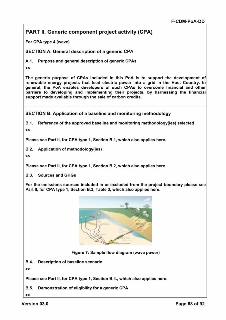
F-CDM-PoA-DD
Version 03.0 Page 68 of 92
PART II. Generic component project activity (CPA)
For CPA type 4 (wave)
SECTION A. General description of a generic CPA
A.1. Purpose and general description of generic CPAs >> The generic purpose of CPAs included in this PoA is to support the development of renewable energy projects that feed electric power into a grid in the Host Country. In general, the PoA enables developers of such CPAs to overcome financial and other barriers to developing and implementing their projects, by harnessing the financial support made available through the sale of carbon credits.
SECTION B. Application of a baseline and monitoring methodology
B.1. Reference of the approved baseline and monitoring methodology(ies) selected >> Please see Part II, for CPA type 1, Section B.1, which also applies here.
B.2. Application of methodology(ies) >> Please see Part II, for CPA type 1, Section B.2, which also applies here.
B.3. Sources and GHGs
For the emissions sources included in or excluded from the project boundary please see Part II, for CPA type 1, Section B.3, Table 3, which also applies here.
Figure 7: Sample flow diagram (wave power)
B.4. Description of baseline scenario >> Please see Part II, for CPA type 1, Section B.4., which also applies here.
B.5. Demonstration of eligibility for a generic CPA >>

F-CDM-PoA-DD
Version 03.0 Page 69 of 92
Confirming compliance with the PoA eligibility criteria: Please see Part II, for CPA type 1, Section B.5., under the heading “Confirming compliance with the PoA eligibility criteria,” for EC#s 1-13 of which also apply here. EC# 7 is further elaborated below with respect to conditions that are specific to this CPA type. Table 4. Eligibility compliance check (wave power CPAs) EC# Item Means of demonstrating
compliance Compliance check
7 Confirming additionality. CPAs applying wave technology must provide documentary evidence that their registration as CDM projects alleviates each of the identified barriers to CPA-type 4 listed in Part I Section B.1, to a level that the project is not prevented from occurring.
[Refer to relevant supporting documentation]
Confirming additionality at the CPA level: Please see Part II, for CPA type 1, Section B.5 under the heading “Confirming additionality at the CPA level,” which also applies here. Common Practice Analysis There are no wave power installations in the Philippines. Hence, wave power is not common practice in the Philippines.
B.6. Estimation of emission reductions of a generic CPA
B.6.1, Explanation of methodological choices >> Please see Part II, for CPA type 1, Section B.6.1., which also applies here. Baseline emissions For projects performing combined margin calculations while determining a grid emission factor: (a) Weighted average CM The combined margin emissions factor is calculated as follows:
BMyBM,grid,OMyOM,grid,yCM,grid, wEFwEFEF ×+×= (3) Where: EFgrid,BM,y = Build margin CO2 emission factor in year y (tCO2/MWh) EFgrid,OM,y = Operating margin CO2 emission factor in year y (tCO2/MWh) wOM = 50% wBM = 50%
B.6.2. Data and parameters that are to be reported ex-ante >>
(Copy this table for each data and parameter.)
Please see Part II, for CPA type 1, Section B.6.2., which also applies here. Fixed parameters:

F-CDM-PoA-DD
Version 03.0 Page 70 of 92
For CPAs connected to the Luzon-Visayas interconnected regional grid or the Mindoro regional grid, the following parameter associated with calculations of the grid emission factor is specific to the CPA type. For CPA type 4:
Data / Parameter: EFgrid,CM
Data unit: tCO2/MWh Description: CO2 emission factors for electricity displaced from the relevant
regional grid. Source of data: Calculated, based on electricity generation data. Value(s) applied: Values are grid specific. PoA-level calculation results:
0.511 for the Luzon-Visayas interconnected regional grid. 0.761 for the Mindoro regional grid.
Choice of data or Measurement methods and procedures:
This parameter is to be calculated for the relevant grid system to which a given CPA is connected. For CPAs connected to the Luzon-Visayas interconnected regional grid and the Mindoro regional grid, this parameter has been calculated ex ante and established at the PoA level, in accordance with the “Tool to calculate the emission factor for an electricity system” (Version 03.0.0).
Purpose of data Calculation of baseline emissions Additional comment:
None
B.6.3. Ex-ante calculations of emission reductions >> Please see Part II, for CPA type 1, Section B.6.3., which also applies here.
B.7. Application of the monitoring methodology and description of the monitoring plan
B.7.1. Data and parameters to be monitored by each generic CPA
(Copy this table for each data and parameter).
Please see Part II, for CPA type 1, Section B.7.1., which also applies here.
B.7.2. Description of the monitoring plan for a generic CPA >> Please see Part II, for CPA type 1, Section B.7.2., which also applies here.

F-CDM-PoA-DD
Version 03.0 Page 71 of 92
PART II. Generic component project activity (CPA)
For CPA type 5 (tidal)
SECTION A. General description of a generic CPA
A.1. Purpose and general description of generic CPAs >> The generic purpose of CPAs included in this PoA is to support the development of renewable energy projects that feed electric power into a grid in the Host Country. In general, the PoA enables developers of such CPAs to overcome financial and other barriers to developing and implementing their projects, by harnessing the financial support made available through the sale of carbon credits.
SECTION B. Application of a baseline and monitoring methodology
B.1. Reference of the approved baseline and monitoring methodology(ies) selected >> Please see Part II, for CPA type 1, Section B.1, which also applies here.
B.2. Application of methodology(ies) >> Please see Part II, for CPA type 1, Section B.2, which also applies here.
B.3. Sources and GHGs
For the emissions sources included in or excluded from the project boundary please see Part II, for CPA type 1, Section B.3, Table 3, which also applies here.
Figure 8: Sample flow diagram (tidal power)
B.4. Description of baseline scenario >>

F-CDM-PoA-DD
Version 03.0 Page 72 of 92
Please see Part II, for CPA type 1, Section B.4., which also applies here.
B.5. Demonstration of eligibility for a generic CPA >> Confirming compliance with the PoA eligibility criteria: Please see Part II, for CPA type 1, Section B.5., under the heading “Confirming compliance with the PoA eligibility criteria,” for EC#s 1-13 of which also apply here. EC# 7 is further elaborated below with respect to conditions that are specific to this CPA type. Table 4. Eligibility compliance check (tidal power CPAs) EC# Item Means of demonstrating
compliance Compliance check
7 Confirming additionality. CPAs applying tidal technology must provide documentary evidence that their registration as CDM projects alleviates each of the identified barriers to CPA-type 4 listed in Part I Section B.1, to a level that the project is not prevented from occurring.
[Refer to relevant supporting documentation]
Confirming additionality at the CPA level: Please see Part II, for CPA type 1, Section B.5 under the heading “Confirming additionality at the CPA level,” which also applies here. Common Practice Analysis There are no tidal power installations in the Philippines. Hence, tidal power is not common practice in the Philippines.
B.6. Estimation of emission reductions of a generic CPA
B.6.1, Explanation of methodological choices >> Please see Part II, for CPA type 1, Section B.6.1., which also applies here. Baseline emissions For projects performing combined margin calculations while determining a grid emission factor: (a) Weighted average CM The combined margin emissions factor is calculated as follows:
BMyBM,grid,OMyOM,grid,yCM,grid, wEFwEFEF ×+×= (3) Where: EFgrid,BM,y = Build margin CO2 emission factor in year y (tCO2/MWh) EFgrid,OM,y = Operating margin CO2 emission factor in year y (tCO2/MWh) wOM = 50% wBM = 50%
B.6.2. Data and parameters that are to be reported ex-ante >>

F-CDM-PoA-DD
Version 03.0 Page 73 of 92
(Copy this table for each data and parameter.)
Please see Part II, for CPA type 1, Section B.6.2., which also applies here. Fixed parameters: For CPAs connected to the Luzon-Visayas interconnected regional grid or the Mindoro regional grid, the following parameter associated with calculations of the grid emission factor is specific to the CPA type. For CPA type 5:
Data / Parameter: EFgrid,CM
Data unit: tCO2/MWh Description: CO2 emission factors for electricity displaced from the relevant
regional grid. Source of data: Calculated, based on electricity generation data. Value(s) applied: Values are grid specific. PoA-level calculation results:
0.511 for the Luzon-Visayas interconnected regional grid. 0.761 for the Mindoro regional grid.
Choice of data or Measurement methods and procedures:
This parameter is to be calculated for the relevant grid system to which a given CPA is connected. For CPAs connected to the Luzon-Visayas interconnected regional grid and the Mindoro regional grid, this parameter has been calculated ex ante and established at the PoA level, in accordance with the “Tool to calculate the emission factor for an electricity system” (Version 03.0.0).
Purpose of data Calculation of baseline emissions Additional comment:
None
B.6.3. Ex-ante calculations of emission reductions >> Please see Part II, for CPA type 1, Section B.6.3., which also applies here.
B.7. Application of the monitoring methodology and description of the monitoring plan
B.7.1. Data and parameters to be monitored by each generic CPA
(Copy this table for each data and parameter).
Please see Part II, for CPA type 1, Section B.7.1., which also applies here.
B.7.2. Description of the monitoring plan for a generic CPA >> Please see Part II, for CPA type 1, Section B.7.2., which also applies here.

F-CDM-PoA-DD
Version 03.0 Page 74 of 92
PART II. Generic component project activity (CPA)
For CPA type 6 (geothermal)
SECTION A. General description of a generic CPA
A.1. Purpose and general description of generic CPAs >> The generic purpose of CPAs included in this PoA is to support the development of renewable energy projects that feed electric power into an interconnected or regional grid. In general, the PoA enables developers of such CPAs to overcome financial and other barriers to developing and implementing their projects, by harnessing the financial support made available through the sale of carbon credits.
SECTION B. Application of a baseline and monitoring methodology
B.1. Reference of the approved baseline and monitoring methodology(ies) selected >> Please see Part II. , for CPA type 1, Section B.1, which also applies here
B.2. Application of methodology(ies) >> Table 2. Relevance of ACM0002 to the proposed PoA Applicability Condition from the Meth Relevance to Proposed PoA This methodology is applicable to grid-connected renewable power generation project activities that: (a) install a new power plant at a site where no renewable power plant was operated prior to the implementation of the project activity (greenfield plant); (b) involve a capacity addition; (c) involve a retrofit of (an) existing plant(s); or (d) involve a replacement of (an) existing plant(s).
The proposed PoA is applicable to project activities that install a new power plant at a site where there was no renewable energy power plant operating prior to the implementation of the project activity (Greenfield plant). The proposed PoA is not applicable to project activities that involve capacity additions, retrofits of existing plants, or replacements of existing plants. Adherence to this condition shall be confirmed through supporting studies or documentation such as feasibility studies and/or business plans.
F-CDM-PoA-DD
Version 03.0 Page 75 of 92
The methodology is applicable under the following conditions: • The project activity is the installation,
capacity addition, retrofit or replacement of a power plant/unit of one of the following types: hydro power plant/unit (either with a run-of-river reservoir or an accumulation reservoir), wind power plant/unit, geothermal power plant/unit, solar power plant/unit, wave power plant/unit or tidal power plant/unit;
• In the case of capacity additions, retrofits or replacements (except for wind, solar, wave or tidal power capacity addition projects which use Option 2 on page 10 of version 13.0.0 of the methodology to calculate the parameter EGPJ,y): the existing plant started commercial operation prior to the start of a minimum historical reference period of five years, used for the calculation of baseline emissions and defined in the baseline emission section, and no capacity expansion or retrofit of the plant has been undertaken between the start of this minimum historical reference period and the implementation of the project activity.;
The proposed PoA is applicable to installation of greenfield run-of-river hydro, wind, geothermal, solar PV, wave and tidal power plants/units supplying electricity to a grid. The PoA is not applicable to solar thermal projects. The PoA is not applicable to hydropower projects that create new accumulation reservoirs or increase the volume of an existing reservoir. Adherence to this condition shall be confirmed through supporting studies or documentation such as feasibility studies and/or business plans.
In case of hydro power plants: • One of the following conditions must apply:
o The project activity is implemented in an existing single or multiple reservoirs, with no change in the volume of any of the reservoirs; or
o The project activity is implemented in an existing single or multiple reservoirs, where the volume of any of the reservoirs is increased and the power density of each reservoir, as per the definitions given in the project emissions section, is greater than 4 W/m2; or
o The project activity results in new single or multiple reservoirs and the power density of each reservoir, as per the definitions given in the project emissions section, is greater than 4 W/m2.
As this CPA type does not relate to hydro this condition does not apply.
In case of hydro power plants using multiple reservoirs where the power density of any of the reservoirs is lower than 4 W/m2 all of the following conditions must apply:
• The power density calculated for the entire project activity using equation 5 is greater than 4 W/m2;
• Multiple reservoirs and hydro power plants located at the same river and where are designed together to function as an integrated project that collectively constitute the generation capacity of the
As this CPA type does not relate to hydro this condition does not apply.
F-CDM-PoA-DD
Version 03.0 Page 76 of 92
combined power plant; • Water flow between multiple reservoirs is
not used by any other hydropower unit which is not a part of the project activity;
• Total installed capacity of the power units, which are driven using water from the reservoirs with a power density lower than 4 W/m2, is lower than 15 MW;
• Total installed capacity of the power units, which are driven using water from reservoirs with a power density lower than 4 W/m2, is less than 10% of the total installed capacity of the project activity from multiple reservoirs.
The methodology is not applicable to the following: • Project activities that involve switching from
fossil fuels to renewable energy sources at the site of the project activity, since in this case the baseline may be the continued use of fossil fuels at the site;
• Biomass fired power plants; • A hydro power plant that results in the
creation of a new single reservoir or in the increase in an existing single reservoir where the power density of the reservoir is less than 4 W/m2.
As this CPA type relates to greenfield geothermal projects, this condition is met.
In the case of retrofits, replacements, or capacity additions, this methodology is only applicable if the most plausible baseline scenario, as a result of the identification of baseline scenario, is “the continuation of the current situation, i.e. to use the power generation equipment that was already in use prior to the implementation of the project activity and undertaking business as usual maintenance”.
The proposed PoA is only applicable to greenfield project activities. Therefore, this applicability condition is not relevant.
In addition, the applicability conditions included in the tools referred to above apply.60 Relevant tools:
• “Tool to calculate the emission factor for an electricity system”;
• “Tool for the demonstration and assessment of additionality”;
• “Combined tool to identify the baseline scenario and demonstrate additionality”;
• “Tool to calculate project or leakage CO2 emissions from fossil fuel combustion”.
The proposed PoA incorporates this requirement in its applicability conditions. As such, the following applicability conditions apply: From the Tool to calculate the emission factor for an electricity system, version 03.0.0:
• “This tool may be applied to estimate the OM, BM and/or CM when calculating baseline emissions for a project activity that substitutes grid electricity, i.e. where a project activity supplies electricity to a grid or a project activity that results in savings
60 The condition in the “Combined tool to identify the baseline scenario and demonstrate additionality” that all potential
alternative scenarios to the proposed project activity must be available options to project participants does not apply to this methodology, as this methodology only refers to some steps of this tool.
F-CDM-PoA-DD
Version 03.0 Page 77 of 92
of electricity that would have been provided by the grid (e.g. demand-side energy efficiency projects).”
This PoA is only applicable to project activities that supply electricity to a grid. Hence all CPAs under this PoA adhere to this condition.
• “In case of CDM projects the tool is not applicable if the project electricity system is located partially or totally in an Annex I country.”
This PoA is only applicable to CDM project activities. Hence all CPAs under this PoA adhere to this condition. From the Tool for the demonstration and assessment of additionality, version 7.0.0:
• “Project activities that apply this tool in context of approved consolidated methodology ACM0002, only need to identify that there is at least one credible and feasible alternative that would be more attractive than the proposed project activity.”
This PoA applies ACM0002. Therefore, CPAs under this PoA need only identify one credible and feasible alternative that would be more attractive than the proposed project activity. This applicability condition shall be reflected in the additionality assessment for each CPA. From the “Tool to calculate project or leakage CO2 emissions from fossil fuel combustion,” version 2 (relevant for geothermal projects):
• “This tool provides procedures to calculate project and/or leakage CO2 emissions from the combustion of fossil fuels. It can be used in cases where CO2 emissions from fossil fuel combustion are calculated based on the quantity of fuel combusted and its properties.”
This applicability condition is relevant to geothermal project activities implemented under this PoA that combust fossil fuels. In such cases, correct application of this tool shall be demonstrated in the CPA-DD.
B.3. Sources and GHGs
Table 7 Emissions sources included in or excluded from the project boundary
Source Gas Included Justification/Explanation

F-CDM-PoA-DD
Version 03.0 Page 78 of 92
Bas
elin
e
CO2 emissions from electricity generation in fossil fuel fired power plants that are displaced due to the project activity
CO2 Yes Main emission source CH4 No Minor emission source
N2O No Minor emission source
Proj
ect a
ctiv
ity
For geothermal power plants, fugitive emissions of CH4 and CO2 from non-condensable gases contained in geothermal steam
CO2 Yes Main emission source CH4 Yes Main emission source
N2O No
Minor emission source
CO2 emissions from combustion of fossil fuels for electricity generation in geothermal power plants
CO2 Yes Main emission source CH4 No Minor emission source
N2O No Minor emission source
Figure 9: Sample flow diagram (geothermal)
B.4. Description of baseline scenario >> Please see Part II, for CPA type 1, Section B.4., which also applies here.
B.5. Demonstration of eligibility for a generic CPA >> Confirming compliance with the PoA eligibility criteria: Please see Part II, for CPA type 1, Section B.5., under the heading “Confirming compliance with the PoA eligibility criteria” for EC#s 1-13 of which also apply here. EC# 7 is further elaborated below with respect to conditions that are specific to this CPA type. Table 4. Eligibility compliance check (geothermal CPAs)
F-CDM-PoA-DD
Version 03.0 Page 79 of 92
EC# Item Means of demonstrating compliance
Compliance check
7 CPAs electing to perform an investment analysis shall conform to the a) technical and b) economic parameters established under each CPA type
a) CPA developers shall demonstrate that their project falls within the allowable ranges for load factors of the technology to be applied as specified under each generic CPA type in Part II. The load factor for geothermal power projects in the Philippines shall be within the range of 70- 90%61. b) Further they shall utilize the key items of capital expenditure that are specified under each generic CPA type in Part II in preparing their analysis The capital expenditures geothermal power projects in the Philippines shall include:
i. Equipment cost (e.g steam turbines, generators, steam/water separators, heat exchangers), transportation from country of origin to project site, and balance of plant) range from US$955-4,35062/ kW;
ii. VAT on imported goods 30% of 12%63;
iii. Civil engineering range from US$1,555-2,870/ kW64;
iv. transmission lines to grid maximum US$84,000/ km65;
v. service/ access road US$20,000/ km66 +10% ;
vi. construction contingency 7.5%67 of total project cost;
vii. Initial working capital 1.75%68 of EPC;
[Refer to relevant supporting documentation]s
61 See table 1 & associated notes 62 See table 1 & associated notes 63 Common price quoted for other CPA types 64 See table 1 & associated notes 65 Common price quoted for other CPA types 66 Common price quoted for other CPA types 67 Average price quoted for other CPA types
F-CDM-PoA-DD
Version 03.0 Page 80 of 92
viii. development costs (e.g. land, permits) 1.5%69 of EPC (i-vii).
Confirming additionality at the CPA level: Please see Part II, for CPA type 1, Section B.5 under the heading “Confirming additionality at the CPA level,” which also applies here. Apply the framework established in Part I, Section B.1, Procedure 2, Step 3 using the general and the wind power specific parameters as defined in eligibility criterion #7 above as follows:
• Input parameters (duly documented as to source) o General (year of assumptions & relevant exchange rates) o Geothermal specific capital expenditure items or CapEx for: e.g. steam turbines,
generators, steam/water separators, heat exchangers and auxiliary equipment; transportation from country of origin to the project site; balance of plant/ engineering cost; switch yard & transformer costs conforming to the values defined under EC#7 above;
o General CapEx for: transmission line distance and unit cost; access road distance and unit cost; development related costs; contingency; tax on imported goods if relevant; and initial working capital conforming to the values defined under EC#7 above;
o Operation and maintenance costs or OpEx (cost of spare parts and maintenance equipment, staff costs and yearly O&M cost);
o Revenues (installed capacity, net capacity factor, operating hours/ year, electricity tariff and grid emission factor);
The above input values shall be used to derive:
• Total project costs or TPC (the sum of CapEx and OpEx) for each year of the project cycle and CER crediting period;
• Yearly project revenues; • A pre-tax net cash flow; and finally • The pre-tax project IRR derived from all net cash flows.
A sensitivity analysis shall be performed as follows unless this is not deemed appropriate in the context of the specific project circumstances:
• Plus and minus 10% of the revenues from power sales; • Plus and minus 10% of the CapEx; • Plus and minus 10% of the OpEx/ O&M; and • With CDM revenues.
The pre-tax project IRR shall be compared with the benchmark established in Part I, Section B.1, Procedure 2, Step 3, Sub-step 3b. Common Practice Analysis The following common practice analysis has been carried out in accordance with the Guidelines on Common Practice version 2.0. The details of each step can be found in the guideline and are not repeated here. There are no small-scale geothermal power plants in the Philippines. Hence, small-scale
68 Average price quoted for other CPA types 69 Average price quoted for other CPA types

F-CDM-PoA-DD
Version 03.0 Page 81 of 92
geothermal is not common practice anywhere in the Philippines. Step 1: calculate applicable capacity or output range as +/-50% of the total design capacity or output of the proposed project activity. For geothermal power, we have analyzed one applicable output range: large scale (>15MW). Step 2: identify similar projects (both CDM and non-CDM) which fulfil all of the conditions presented in the Guideline: With the justification presented in Part I Section B.1, we have analyzed two geographical areas: the area connected to the Luzon-Visayas interconnected regional grid, and the area connected to the Mindanao regional grid. However, there are only eight large-scale geothermal plants installed in the Philippines. They are all in Luzon-Visayas and Mindanao. Therefore, large-scale geothermal is not common practice anywhere in the Philippines outside Luzon-Visayas and Mindanao. Luzon-Visayas: There are seven plants. Six were built by the government prior to privatization of the power sector. The seventh is a commercial investment. Mindanao: There is only one geothermal plant. It was built by the government on a non-commercial basis. Step 3: within the projects identified in Step 2, identify those that are neither registered CDM project activities, project activities submitted for registration, nor project activities undergoing validation. Note their number Nall. Large-scale Visayas: The one commercial plant was built and is undergoing validation as a CDM project.70 Therefore, Nall = 0. Large scale Mindanao: There are no power plants that meet all of the criteria of Step 2. As Step 3 results in no geothermal power plants for further analysis, commercial investments in geothermal power plants of any size are not common practice in any of the grid systems in the Philippines.
B.6. Estimation of emission reductions of a generic CPA
B.6.1, Explanation of methodological choices >> Emission reductions are calculated as baseline emissions less project emissions and leakage. The methodological choices for each are detailed below. Project Emissions Project emissions for geothermal plants include project emissions from fossil fuel consumption and from the release of non-condensable gases. PEy = PEFF,y + PEGP,y (1) Where: PEy = Project emissions in year y (tCO2e) PEFF,y = Project emissions from fossil fuel consumption in year y (tCO2) PEGP,y = Project emissions from the operation of geothermal power plants due to
70 Northern Negros Geothermal Project
(http://cdm.unfccc.int/Projects/Validation/DB/II78O8UGJQMM3414B3CT5WW03HYJJP/view.html)
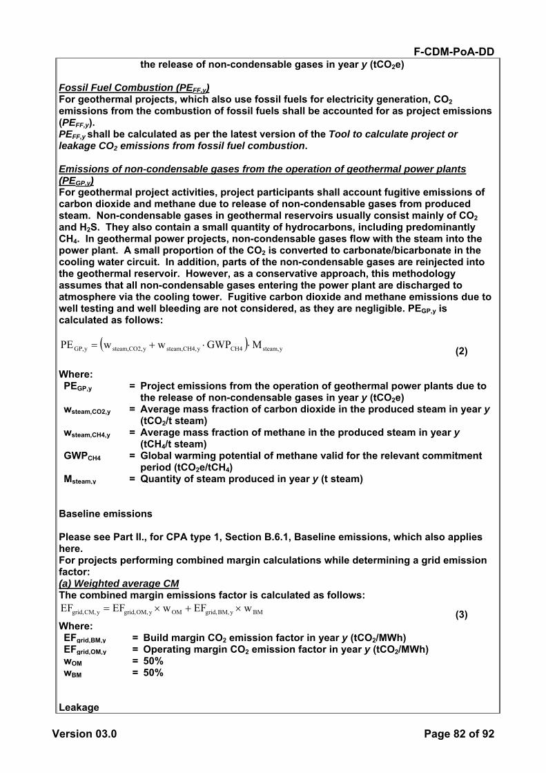
F-CDM-PoA-DD
Version 03.0 Page 82 of 92
the release of non-condensable gases in year y (tCO2e) Fossil Fuel Combustion (PEFF,y) For geothermal projects, which also use fossil fuels for electricity generation, CO2 emissions from the combustion of fossil fuels shall be accounted for as project emissions (PEFF,y). PEFF,y shall be calculated as per the latest version of the Tool to calculate project or leakage CO2 emissions from fossil fuel combustion. Emissions of non-condensable gases from the operation of geothermal power plants (PEGP,y) For geothermal project activities, project participants shall account fugitive emissions of carbon dioxide and methane due to release of non-condensable gases from produced steam. Non-condensable gases in geothermal reservoirs usually consist mainly of CO2 and H2S. They also contain a small quantity of hydrocarbons, including predominantly CH4. In geothermal power projects, non-condensable gases flow with the steam into the power plant. A small proportion of the CO2 is converted to carbonate/bicarbonate in the cooling water circuit. In addition, parts of the non-condensable gases are reinjected into the geothermal reservoir. However, as a conservative approach, this methodology assumes that all non-condensable gases entering the power plant are discharged to atmosphere via the cooling tower. Fugitive carbon dioxide and methane emissions due to well testing and well bleeding are not considered, as they are negligible. PEGP,y is calculated as follows:
( ) ysteam,CH4yCH4,steam,yCO2,steam,yGP, MGWPwwPE ⋅⋅+= (2) Where: PEGP,y = Project emissions from the operation of geothermal power plants due to
the release of non-condensable gases in year y (tCO2e) wsteam,CO2,y = Average mass fraction of carbon dioxide in the produced steam in year y
(tCO2/t steam) wsteam,CH4,y = Average mass fraction of methane in the produced steam in year y
(tCH4/t steam) GWPCH4 = Global warming potential of methane valid for the relevant commitment
period (tCO2e/tCH4) Msteam,y = Quantity of steam produced in year y (t steam)
Baseline emissions Please see Part II., for CPA type 1, Section B.6.1, Baseline emissions, which also applies here. For projects performing combined margin calculations while determining a grid emission factor: (a) Weighted average CM The combined margin emissions factor is calculated as follows:
BMyBM,grid,OMyOM,grid,yCM,grid, wEFwEFEF ×+×= (3) Where: EFgrid,BM,y = Build margin CO2 emission factor in year y (tCO2/MWh) EFgrid,OM,y = Operating margin CO2 emission factor in year y (tCO2/MWh) wOM = 50% wBM = 50%
Leakage
F-CDM-PoA-DD
Version 03.0 Page 83 of 92
As per ACM0002 version 13.0.0 no leakage emissions are considered. Emission reductions: Emission reductions for a CPA shall be calculated as follows:
(11) Where:
Emission reductions in year y (t CO2e)
Baseline Emissions in year y (t CO2)
Project emissions in year y (t CO2e)
Estimation of emissions reductions prior to validation Please see Part II., for CPA type 1, Section B.6.1, Estimation of emission reductions prior to validation, which also applies here. Changes required for methodology implementation in 2nd and 3rd crediting periods Please see Part II., for CPA type 1, Section B.6.1, Changes required for methodology implementation in 2nd and 3rd crediting periods, which also applies here.
B.6.2. Data and parameters that are to be reported ex-ante >>
(Copy this table for each data and parameter.)
Fixed parameters: The following parameters are fixed for all CPAs included during the first 7 years of the PoA crediting period and for the respective first 7-year crediting period of these CPAs. These parameters are to be updated at the PoA level at the start of the second and third crediting periods of the PoA:
Data / Parameter: GWPCH4 Data unit: tCO2e/tCH4 Description: Global warming potential of methane valid for the relevant
commitment period Source of data: IPCC Value(s) applied: For the first commitment period: 21 tCO2e/tCH4 Choice of data or Measurement methods and procedures:
Defined in the methodology.
Purpose of data Calculation of project emissions Additional comment:
Used exclusively for geothermal projects
For parameters associated with calculations of the grid emission factor see Part II., for CPA type 1, Section B.6.2, which also applies here. For CPAs connected to the Luzon-Visayas interconnected regional grid or the Mindoro
yyy PEBEER −=
yER
yBE
yPE
F-CDM-PoA-DD
Version 03.0 Page 84 of 92
regional grid, the following parameter associated with calculations of the grid emission factor is specific to the CPA type. For CPA type 6:
Data / Parameter: EFgrid,CM
Data unit: tCO2/MWh Description: CO2 emission factors for electricity displaced from the relevant
regional grid. Source of data: Calculated, based on electricity generation data. Value(s) applied: Values are grid specific. PoA-level calculation results:
0.511 for the Luzon-Visayas interconnected regional grid, except for solar and wind projects. 0.761 for the Mindoro regional grid.
Choice of data or Measurement methods and procedures:
This parameter is to be calculated for the relevant grid system to which a given CPA is connected. For CPAs connected to the Luzon-Visayas interconnected regional grid and the Mindoro regional grid, this parameter has been calculated ex ante and established at the PoA level, in accordance with the “Tool to calculate the emission factor for an electricity system” (Version 03.0.0).
Purpose of data Calculation of baseline emissions Additional comment:
None
B.6.3. Ex-ante calculations of emission reductions >> Please see Part II, for CPA type 1, Section B.6.3., which also applies here.
B.7. Application of the monitoring methodology and description of the monitoring plan
B.7.1. Data and parameters to be monitored by each generic CPA
(Copy this table for each data and parameter).
Data / Parameter: EGfacility,y Data unit: MWh/yr Description: Quantity of net electricity generation supplied by the project
plant/unit to the grid in year y Source of data: Project activity site Value(s) applied [number]
F-CDM-PoA-DD
Version 03.0 Page 85 of 92
Measurement methods and procedures:
The following parameters shall be measured: (i) The quantity of electricity supplied by the project plant/unit to the grid; and (ii) The quantity of electricity delivered to the project plant/unit from the grid Electricity meters The meter shall be installed at the point of connection to the grid as agreed with the grid operator. A high level of accuracy of the measurements will be achieved through the use of high-precision equipment calibrated and tested according to recognized standards and agreed with the grid operator. NOTE: The electricity meter owned by the grid operator is managed and maintained under the sole responsibility of the grid operator and according to their internal standards. Therefore, it is it is not under the control of the CPA .
Monitoring frequency:
Continuous measurement and at least monthly recording
QA/QC procedures: QC: Measurement results shall be cross checked with records for sold/purchased electricity (e.g. invoices/receipts). If values differ, the value produced from the meter with the highest precision shall be used. QA: The meter will be re-calibrated at least once a year by a third party entity. QC: There will be strict compliance with the meter maintenance schedule recommended by the technology provider and/or the grid operator.
Purpose of data Calculation of baseline emissions Additional comment:
None
Data / Parameter: wsteam,CO2,y Data unit: tCO2/t steam Description: Average mass fraction of carbon dioxide in the produced steam
in year y Source of data: Project activity site Value(s) applied [number] Measurement methods and procedures:
Non-condensable gases sampling should be carried out in production wells and at the steam field-power plant interface using ASTM Standard Practice E1675 for Sampling 2-Phase Geothermal Fluid for Purposes of Chemical Analysis (as applicable to sampling single phase steam only). The CO2 and CH4 sampling and analysis procedure consists of collecting non-condensable gases samples from the main steam line with glass flasks, filled with sodium hydroxide solution and additional chemicals to prevent oxidation. Hydrogen sulphide (H2S) and carbon dioxide (CO2) dissolve in the solvent while the residual compounds remain in their gaseous phase. The gas portion is then analyzed using gas chromatography to determine the content of the residuals including CH4. All alkanes concentrations are reported in terms of methane
F-CDM-PoA-DD
Version 03.0 Page 86 of 92
Monitoring frequency:
At least every 3 months and more frequently, if necessary
QA/QC procedures: Not applicable Purpose of data Calculation of project emissions Additional comment:
Applicable to geothermal power projects
Data / Parameter: wsteam,CH4,y Data unit: tCH4/t steam Description: Average mass fraction of methane in the produced steam in
year y Source of data: Project activity site Value(s) applied [number]Measurement methods and procedures:
As per the procedures outlined for wsteam,CO2,y
Monitoring frequency:
As per the procedures outlined for wsteam,CO2,y
QA/QC procedures: Not applicable Purpose of data Calculation of project emissions Additional comment:
Applicable to geothermal power projects
Data / Parameter: Msteam,y Data unit: t steam/yr Description: Quantity of steam produced in year y Source of data: Project activity site Value(s) applied [number] Measurement methods and procedures:
The steam quantity discharged from the geothermal wells should be measured with a venture flow meter (or other equipment with at least the same accuracy). Measurement of temperature and pressure upstream of the venture meter is required to define the steam properties. The calculation of steam quantities should be conducted on a continuous basis and should be based on international standards. The measurement results should be summarized transparently in regular production reports
Monitoring frequency:
Daily
QA/QC procedures: Not applicable Purpose of data Calculation of project emissions Additional comment:
Applicable to geothermal power projects
Data / Parameter: EFgrid,CM,y

F-CDM-PoA-DD
Version 03.0 Page 87 of 92
Data unit: tCO2/MWh Description: Combined margin CO2 emission factor for grid connected
power generation in year y calculated using the latest version of the “Tool to calculate the emission factor for an electricity system”
Source of data: As per the “Tool to calculate the emission factor for an electricity system”
Value(s) applied For projects connected to the Luzon-Visayas interconnected regional grid: 0.529 For projects connected to the Mindoro regional grid,: 0.776 For projects connected to other grids: [number]
Measurement methods and procedures:
As per the “Tool to calculate the emission factor for an electricity system”
Monitoring frequency:
As per the “Tool to calculate the emission factor for an electricity system”
QA/QC procedures: As per the “Tool to calculate the emission factor for an electricity system”
Purpose of data Calculation of baseline emissions Additional comment:
For CPAs connected to the Luzon-Visayas integrated regional grid or the Mindoro regional grid the value established ex ante at the PoA-level shall be applied and need not be monitored during the crediting period.
Data / Parameter: PEFF,y Data unit: tCO2 Description: Project emissions from fossil fuel consumption in year y Source of data: As per the “Tool to calculate project or leakage CO2 emissions
from fossil fuel combustion” Value(s) applied [number] Measurement methods and procedures:
As per the “Tool to calculate project or leakage CO2 emissions from fossil fuel combustion”
Monitoring frequency:
As per the “Tool to calculate project or leakage CO2 emissions from fossil fuel combustion”
QA/QC procedures: As per the “Tool to calculate project or leakage CO2 emissions from fossil fuel combustion”
Purpose of data Calculation of project emissions Additional comment:
Applicable to geothermal projects that also use fossil fuels for electricity generation
B.7.2. Description of the monitoring plan for a generic CPA >> Please see Part II., for CPA type 1, Section B.7.2, which also applies here.
F-CDM-PoA-DD
Version 03.0 Page 88 of 92
Appendix 1. Contact information on entity/individual responsible for the PoA
Organization Carbonergy Business Consultancy Services Street/P.O. Box 203 Banaue Street, Ayala Alabang Village Building N/A City Muntinlupa City State/Region Metro Manila Postcode 1780 Country Philippines Telephone +63 2 809 7826 Fax N/A E-mail [email protected] Website www.climatebusiness.net/carbonergy Contact person Dr. Peter Pembleton Title Chief Executive Officer Salutation Dr. Last name Pembleton Middle name Noel First name Peter Department N/A Mobile +63 917 826 2688
Organization Cornland International AB
Street/P.O. Box Hagabergsvägen 5 Building N/A City Svartsjö State/Region N/A Postcode SE 17996 Country Sweden Telephone +46 8 560 40850 Fax N/A E-mail [email protected] Website N/A Contact person Deborah Cornland Title Director Salutation Dr. Last name Cornland Middle name Wilson First name Deborah Department N/A Mobile N/A

F-CDM-PoA-DD
Version 03.0 Page 89 of 92
Organization Bulalacao Wind Power Corp. Street/P.O. Box 210N. Garcia Street Building 318B LRI Business Plaza City Bel-Air, Makati City State/Region Metro Manila Postcode N/A Country Philippines Telephone +63 2 403 6389 Fax N/A E-mail [email protected] Website N/A Contact person Ms. Ruth Yu-Owen Title Ms. Salutation President Last name Yu-Owen Middle name N/A First name Ruth Department N/A Mobile +63 917 527 5466
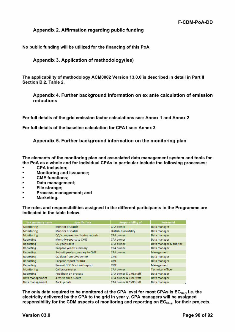
F-CDM-PoA-DD
Version 03.0 Page 90 of 92
Appendix 2. Affirmation regarding public funding
No public funding will be utilized for the financing of this PoA.
Appendix 3. Application of methodology(ies)
The applicability of methodology ACM0002 Version 13.0.0 is described in detail in Part II Section B.2. Table 2.
Appendix 4. Further background information on ex ante calculation of emission reductions
For full details of the grid emission factor calculations see: Annex 1 and Annex 2 For full details of the baseline calculation for CPA1 see: Annex 3
Appendix 5. Further background information on the monitoring plan
The elements of the monitoring plan and associated data management system and tools for the PoA as a whole and for individual CPAs in particular include the following processes: • CPA inclusion; • Monitoring and issuance; • CME functions; • Data management; • File storage; • Process management; and • Marketing. The roles and responsibilities assigned to the different participants in the Programme are indicated in the table below.
The only data required to be monitored at the CPA level for most CPAs is EGBL,y i.e. the electricity delivered by the CPA to the grid in year y. CPA managers will be assigned responsibility for the CDM aspects of monitoring and reporting on EGBL,y, for their projects.
F-CDM-PoA-DD
Version 03.0 Page 91 of 92
According to Philippine Republic Act 9513, project developers that wish to avail themselves of incentives are required to enter into a Renewable Energy Payment Agreement (REPA) that includes a ‘Transmission Services Agreement’ and a ‘Metering Services Agreement’ with the National Grid Corporation (NGCP) of the Philippines in order to sell their power to the grids that are operated by NGCP. Traditional power purchase agreements and associated terms will be negotiated with the respective sub-grid operators, and similar procedures will apply, for all projects connected to regional grids, as well as for those developers that do not wish to avail themselves of the RE incentives. According to these agreements, NGCP shall install a revenue meter, or such applicable metering device and/or related instruments, to measure and record the delivery of electricity generated by the RE Plant to the relevant Grid (“Revenue Meter”) at the physical delivery point or where the high-voltage side of the step-up transformer of the RE Plant is located (“Metering Point”). While NGCP-approved meters shall be utilized in the measurement of the electricity deliveries received from the RE Developer, the Developer shall install and maintain its own nationally/ NGCP-approved meter in close proximity to the Metering Point. The actual kilowatt-hours delivered by the Developer will be read from its meter on a monthly basis at an agreed concurrent time with NGCP’s reading of its own meter. The RE Developer shall record the values in its own monthly ‘Record of Meter Reading’ and shall prepare and present a signed Record of Meter Reading to NGCP on the first Business Day following each reading. NGCP shall check against the concurrent reading taken at its own meter and co-sign the Record of Meter Reading and return to the RE Developer. In the event of exceptions or disputes, the Parties shall confer within two (2) Business Days thereafter to resolve any such exceptions and disputes. In the event that the dispute is not resolved within such time, the reading of NGCP shall prevail while reasons for the discrepancy are sought including possible re-calibration of the meters. The RE Developer will appoint a CDM Manager, possibly supported by a data manager, who will be responsible for the above-mentioned monitoring process. The CDM Manager will: generate primary data through its own monitoring; collate and store the primary data in hard copy and electronic form; cross-check their data against invoices for electricity sales; aggregate primary data into electronic data sets and reports; control the quality of data entered into electronic storage media; transmit the data to the CME; and secure the records through backups and mirror sites. The CDM Manager will also store hard and soft copies of the data, sales receipts and meter calibration reports. The CME has developed an electronic template using Microsoft Excel to manage the incoming monitoring data—this template will be provided to the CDM Manager of all CPAs to ensure consistency in the format of reporting. The CME will collect and store other information from and about the CPAs namely: basic information on the CPA; meter data; key reference documents; a process checklist; a permits checklist; and the DNA requirements checklist. The CME has developed a set of data and management tools in order to: ensure accuracy,
quality and reliability of data (EGBL,y and, where appropriate ) monitoring; and ensure transparency of the processes; avoid duplication of submissions for registration and claims for CERs; organize and store data for ease-of-recall; and manage the numerous processes of the PoA. The data in the system will be regularly updated to reflect a project’s status as it progresses through the stages of development and implementation. In addition, the templates will be adjusted over time to better monitor data and activities.
- - - - -
historicalσ
F-CDM-PoA-DD
Version 03.0 Page 92 of 92
Document information
Version Date Description
03.0 3 December 2012 Revision to clarify the determination of the start date for a PoA and the documentation requirement for generic CPA-DDs. (EB 70, Annex 6).
02.0 11 May 2012 EB 66, Annex 12 Revision required to ensure consistency with the "Guidelines for completing the programme design document form for CDM programmes of activities".
01.0 2 March 2012 EB 33, Annex 41 Initial adoption.
Decision Class: Regulatory Document Type: Form Business Function: issuance Keywords: project design document, programmes of activities