f series: steel tube a series: aluminum tube · inductive sensor,rod with gir series ball joint and...
TRANSCRIPT

02LINEAR ACTUATORS
F series: Steel tubeA series: Aluminum tube
Page: 070

Page: 071

“WE ARE WHAT WE REPEATEDLY DO. EXCELLENCE, THEN, IS NOT AN ACT, BUT A HABIT.”ARISTOTLEPHILOSOPHY
Page: 072

Page: 073

NIASA F/A Series linear actuators are electro-mechanical
cylinders in which a round stem moves inside a second tube,
of either steel or aluminum.
The lengthwise movement of the stem is achieved with the
combination of an interior screw/nut which drags it, and
an electrical motor that drives the screw/nut. The power
transmission from the motor may be direct or by means of
diAerent gear solutions and toothed belts.
Against solutions with exposed screws, protecting them with
an external stem means that the equipment is very highly
sealed and can operate in the most aggressive conditions,
with the presence of dust or liquid of almost any type in the
environment. The stem provides an extraordinary capacity for
buckle load against axial compression loads.
These types of actuators are the best solution in practically any
application that requires precise and safe linear movement,
whether it is for transfer or for elevation and regardless of the
speed required. Their main advantages against other systems,
such as pneumatic or hydraulic cylinders, are the following:
… Greater movement and positioning precision.
… Superior energy eHciency, as their parts oAer high/very
high performance, especially with the ball screws, low
transmission ratios and high speeds
… Easier and faster assembly, since hydraulic or pneumatic
groups are not required, just an electric motor mounted
on the unit itself.
… Greater reliability and duration, and less maintenance, due
to the mechanical robustness and construction simplicity.
… Lower size for the same load capacity.
… …
The screw supports also characterize for oAering an extensive
range of:
… Axial load capacities, from 3.5 kN up to 86 kN.
… Stem advance speeds depending on the screw pitch and
the transmission used.
… Trapezoidal and ball screws, depending on the
performance required, precision of the desired movement
and positioning, etc.
… Outer tube of steel or extruded aluminum profile.
The latter is, in general, the lightest and enables
immobilization in the stem's rotation
and a magnetic sensor to be integrated.
… Fastening accessories and elements, for optimal
adaptation to the most varied systems that may be
designed.
… Drives, with diAerent reduction ratios and positions with
respect to the cylinder, enable the best solution to be
oAered for any speed and configuration problem. Among
these are the following as standard:
· In line Motors / Motoreducers.
· Motors / Motoreduc. in parallel with the toothed belt.
· Motors / Motoreducers at 90º.
· …
… Control and safety systems (inductive/magnetic stroke
limit switches, absolute/incremental encoders, etc.).
… Materials and surface coverings, depending on the
environmental conditions in which the unit will be
installed.
Please do not hesitate to contact NIASA if you require
actuators (and their drive mechanisms) with specifications
other than those covered in this chapter. The NIASA technical
department will specifically develop the special units that best
meet your requirements.
extensive
itch and
movement
e.
s
mal
ay be
itions with
n to be
lem. Among
thed belt.
etic stroke
ers, etc.).
on the
will be
equire
ecifications
ASA technical
units that best
LINEAR ACTUATORS F SERIES: STEEL TUBE | A SERIES: ALUMINUM TUBE
INTRODUCTION
Page: 074

02
Page: 075 www.niasa.es

LINEAR ACTUATORS F SERIES: STEEL TUBE | A SERIES: ALUMINUM TUBE
APPLICATIONS
SHUTTER SYSTEM
A30 Series actuator made up of a three-
phase motor drive system, tilt on the
outside with BA Series bolts, SB Series
tilt support, clevis rod with GIR Series
ball joint on the stem and integrated
position magnetic sensor.
VERTICAL DRIVE DE SYSTEM
Set of two F30-M505 actuators made
up of a servomotor drive system, a
special drive union flange and joined
together with a GX universal joint shaft.
Inductive sensor, clevis rod with GIR
Series ball joint and protection bellow
for the FB Series stem.
Page: 076

www.niasa.es
02
www.niasa.es
02
HORIZONTAL DRIVE DE SYSTEM
Set of two F30-M205 actuators, made
up of a drive system of a three-phase
line motoreducer, independently
commanded and fastened with SB
Series tilt supports and BP Series
plates on the stem.
SCISSOR LIFT
F45–M501 made up of a three-phase
motor drive system, SB Series tilt
supports and GKB Series double clevis
rod on the stem.
ANTENNA ORIENTATION SYSTEM
A40 Series actuator made up of a
servomotor drive system, drive union
flange, tilt on the outside with BA Series
bolts, SB Series tilt support and GK
Series single clevis rod on the stem.
Page: 077

LINEAR ACTUATORS F SERIES: STEEL TUBE | A SERIES: ALUMINUM TUBE
SIZESF SERIES: Steel outside tube.SERIES A: Aluminum outside tube (stem anti-rotation and magnetic sensor optional).
For further information about M205/M501/M505/M605 A Series configurations, please contact NIASA.There are trapezoidal and ball screw options on all sizes (see chapter 07 about screws for more details).
In addition to the standard range of F/A Series linear actuators, NIASA can specifically
develop the unit that best meets your application requirements. Contact NIASA.
Up to
F16 / A166 kN
F20 / A2010.5 kN
M100Basic configuration page 78 page 80
M205In line motoreducer page 88
M501Parallel drive page 90 page 90
M505For drive at 90º page 92 page 92
M601Motoreducer at 90º page 93
M605In line motor page 94 page 94
Page: 078 www.niasa.es

www.niasa.es
02
F30 / A3023.5 kN
F40 / A4038 kN
F4578 kN
F5086 kN
page 82 page 84 page 86 page 87
page 88 page 88 page 88 page 88
page 90 page 90 page 90 page 90
page 92
page 93 page 93 page 93 page 93
page 94 page 94 page 94 page 94
Page: 079

5
10
9
8
76
4
Steel outside tube10
3
2
11
11
12
Aluminum outside tube
13
141
ACCESSORIES
01 VE wheel 300
02 SB tilt support 276
03BB flanges with bolts for steel tube
272
04Flanges with bearings for BH steel tube
273
05BB flanges with bolts for aluminum tube
274
06 BPS flange 278
07 GIR clevis rod 282
08 GKB double clevis rod 281
09 GK single clevis rod 280
10Inductive limit switch FCI
307
11 FCG magnetic limit switch 308
12Connection sensor input adapter
308
13 Position sensor magnet 308
14 Anti-rotation system
Name Page
LINEAR ACTUATORS F SERIES: STEEL TUBE | A SERIES: ALUMINUM TUBE
GENERAL PRODUCT OVERVIEW
Page: 080 www.niasa.es

www.niasa.es
02
M205 M501 M505 M601 M605
Name F A F A F A F A F A
01 F-M100 series linear actuator
02 A-M100 series linear actuator
03 F flange
04 Flange A
05 EK coupling
06 Motor
07 In line motoreducer
08 Motoreducer at 90º
09 Parallel drive
10 Bevel gearbox at 90º
10 9
3
1 2
5
4
8 7
6
CONFIGURATIONS
Page: 081

www.niasa.es
F16-M100 LINEAR ACTUATORSUP TO 6 kN TrTRAPEZ.
KGS
Screw diameter and step (mm)
Maximum axial strength (kN)
Travel (mm/revol. input)
Performance (%)
Drive torque, MD (Nm)
F (kN), load to move in dynamic
Stroke weight 0
(kg)
Approx. weight each 100 mm of
Stroke (kg)
Tr 16x4 3.5 4 40 (1.59 x F) + 0.38 2 0.75
KGS 1605 6 5 81 (0.98 x F) + 0.25 2 0.75
… Power required: PD (kW) = 0,157x M
D (Nm).
… Contact NIASA if the dynamic load exceeds the critical values indicated, in order to avoid over-heating, buckling and resonance of the unit. See
calculations chapter at the end of the chapter (page 97).
COURSE+ 84
122
Ø48 h8
Ø56
Ø75
15 61 36
Ø32
M26x1,5
20
Ø45
4xØ
11
4xØ
7
Ø40
Ø11 h6
7
Key 4x4x10
DIN6885-A Greasing mechanism DIN71412Straight type A - MT503
A
CHECKED BY -A-
SAFETY MARGIN
6
Ø27H8
45°
2020
36
272 273 276 278 280 281 282 300 307
F
BALLS
The capacities indicated correspond to
the standard input shaft configurations.
Higher capacities are available on request.
The capacities indicated correspond to
the standard input shaft configurations.
Higher capacities are available on request.
Page: 082

www.niasa.es
02
A16-M100 LINEAR ACTUATORSUP TO 6 kN TrTRAPEZ.
KGS
Screw diameter and step (mm)
Maximum axial strength (kN)
Travel (mm/revol. input)
Performance (%)
Drive torque, MD (Nm)
F (kN), load to move in dynamic
Stroke weight 0
(kg)
Approx. weight each 100 mm of
Stroke (kg)
Tr 16x4 3.5 4 40 (1.59 x F) + 0.38 1.7 0.7
KGS 1605 6 5 81 (0.98 x F) + 0.25 1.6 0.7
… Power required: PD (kW) = 0,157x M
D (Nm).
… Contact NIASA if the dynamic load exceeds the critical values indicated, in order to avoid over-heating, buckling and resonance of the unit. See
calculations chapter at the end of the chapter (page 97).
02
274 276 278 282 300 308281280
A
2020
SAFETY MARGIN
35
16 COURSE+ 220
35
Ø11 h6
Ø32
Ø27H8
M26x1,5
20
6
Ø40 H8
Screw and nutgreasing access cap
Key 4x4x10DIN6885-A
4 Ø50
(4x) M5x12
58
BALLS
The capacities indicated correspond to
the standard input shaft configurations.
Higher capacities are available on request.
Page: 083

www.niasa.es
Screw diameter and step (mm)
Maximum axial strength (kN)
Travel (mm/revol. input)
Performance (%)
Drive torque, MD (Nm)
F (kN), load to move in dynamic
Stroke weight 0
(kg)
Approx. weight each 100 mm of
Stroke (kg)
Tr 24x5 9.5 5 35 (2.27 x F) + 0.52 3 1.7
KGS 2005 10.5 5 81 (0.98 x F) + 0.42 3 1.25
KGS 2020 5.5 20 81 (3.93 x F) + 0.48 3 1.25
… Power required: PD (kW) = 0,157x M
D (Nm).
… Contact NIASA if the dynamic load exceeds the critical values indicated, in order to avoid over-heating, buckling and resonance of the unit. See
calculations chapter at the end of the chapter (page 97).
COURSE+ 106
152
Ø72 h8
Ø84
Ø110
30 100 36
Ø35
M27x2
26
Ø66
4xØ
14
4xØ
9
Ø55
Ø14 h6
9
Key 5x5x20DIN6885-A
7
Greasing mechanism DIN71412Straight type A - MT503
A
CHECKED BY -A-
SAFETY MARGIN
Ø29H8
45°
2020
36
F20-M100 LINEAR ACTUATORSUP TO 10.5 kN TrTRAPEZ.
KGS
F
272 273 276 278 280 281 282 300 307
BALLS
The capacities indicated correspond to
the standard input shaft configurations.
Higher capacities are available on request.
Page: 084

www.niasa.es
02
Screw diameter and step (mm)
Maximum axial strength (kN)
Travel (mm/revol. input)
Performance (%)
Drive torque, MD (Nm)
F (kN), load to move in dynamic
Stroke weight 0
(kg)
Approx. weight each 100 mm of
Stroke (kg)
Tr 24x5 9.5 5 35 (2.27 x F) + 0.52 3.85 1.25
KGS 2005 10.5 5 81 (0.98 x F) + 0.42 3.65 1.15
KGS 2020 5.5 20 81 (3.93 x F) + 0.48 3.65 1.15
… Power required: PD (kW) = 0,157x M
D (Nm).
… Contact NIASA if the dynamic load exceeds the critical values indicated, in order to avoid over-heating, buckling and resonance of the unit. See
calculations chapter at the end of the chapter (page 97).
A20-M100 LINEAR ACTUATORSUP TO 10.5 kN TrTRAPEZ.
KGS
02A
calculations chapter
274 276 278 282 300 308281280
Ø40
M27x2
Ø29H8
30 COURSE+ 275
35
26
7
Ø14 h6
Ø55 H8
4Ø70
(4x) M6x15
Screw and nutgreasing access cap
Key 5x5x20DIN6885-A
28
82
2020
SAFETY MARGIN
35
BALLS
The capacities indicated correspond to
the standard input shaft configurations.
Higher capacities are available on request.
Page: 085

www.niasa.es
Screw diameter and step (mm)
Maximum axial strength (kN)
Travel (mm/revol. input)
Performance (%)
Drive torque, MD (Nm)
F (kN), load to move in dynamic
Stroke weight 0
(kg)
Approx. weight each 100 mm of
Stroke (kg)
Tr 36x6 15 6 31 (3.08 x F) + 1.6 8 2.6
KGS 3205 21.5 5 81 (0.98 x F) + 1.3 8 2.6
KGS 3210 23.5 10 81 (1.96 x F) + 1.3 8 2.6
KGS 3220 12 20 81 (3.93 x F) + 1.3 8 2.6
KGS 3240 6 40 81 (7.86 x F) + 1.3 8 2.6
… Power required: PD (kW) = 0,157x M
D (Nm).
… Contact NIASA if the dynamic load exceeds the critical values indicated, in order to avoid over-heating, buckling and resonance of the unit. See
calculations chapter at the end of the chapter (page 97).
F30-M100 LINEAR ACTUATORSUP TO 23.5 kN TrTRAPEZ.
KGS
COURSE+ 124
183
Ø90 h8
Ø106
Ø130
35 130 37
Ø50
M42x2
30
Ø88
4xØ
17
4xØ
11
Ø75
Ø19 h6
11Key 6x6x25DIN6885-A
8
Greasing mechanism DIN71412Straight type A - MT503
A
CHECKED BY -A-
SAFETY MARGIN
(*) If incorporating a KGM 3220 nut,
the safety margin is 15 mm.
Ø43H8
45°
20*20*
37
F
272 273 276 278 280 281 282 300 307
BALLS
The capacities indicated correspond to
the standard input shaft configurations.
Higher capacities are available on request.
Page: 086

www.niasa.es
02
Screw diameter and step (mm)
Maximum axial strength (kN)
Travel (mm/revol. input)
Performance (%)
Drive torque, MD (Nm)
F (kN), load to move in dynamic
Stroke weight 0
(kg)
Approx. weight each 100 mm of
Stroke (kg)
Tr 36x6 15 6 31 (3.08 x F) + 1.6 8 2.3
KGS 3205 21.5 5 81 (0.98 x F) + 1.3 8 2.1
KGS 3210 23.5 10 81 (1.96 x F) + 1.3 8 2.1
KGS 3220 12 20 81 (3.93 x F) + 1.3 8 2.1
KGS 3240 6 40 81 (7.86 x F) + 1.3 8 2.1
… Power required: PD (kW) = 0,157x M
D (Nm).
… Contact NIASA if the dynamic load exceeds the critical values indicated, in order to avoid over-heating, buckling and resonance of the unit. See
calculations chapter at the end of the chapter (page 97).
A30-M100 LINEAR ACTUATORSUP TO 23.5 kN TrTRAPEZ.
KGS
02A
calculations chapter
274 276 278 282 300 308281280
2020
SAFETY MARGIN
40
Ø90
Ø50
M42x2
Ø43H8
35 COURSE + 365
40
26
7
Ø19 h6
Ø70 H8
32
5
Screw and nutgreasing access cap
Key 6x6x25DIN6885-A
(4x) M8x15
105
BALLS
The capacities indicated correspond to
the standard input shaft configurations.
Higher capacities are available on request.
Page: 087

www.niasa.es
Screw diameter and step (mm)
Maximum axial strength (kN)
Travel (mm/revol. input)
Performance (%)
Drive torque, MD (Nm)
F (kN), load to move in dynamic
Stroke weight 0
(kg)
Approx. weight each 100 mm of
Stroke (kg)
Tr 45x7 22 7 29 (3.84 x F) + 1.9 17.1 4.9
KGS 4010 38 10 81 (1.96 x F) + 1.6 16.8 4.2
KGS 4020 21.5 20 81 (3.93 x F) + 1.7 16.8 4.2
KGS 4040 11 40 81 (7.86 x F) + 1.7 16.8 4.2
… Power required: PD (kW) = 0,157x M
D (Nm).
… Contact NIASA if the dynamic load exceeds the critical values indicated, in order to avoid over-heating, buckling and resonance of the unit. See
calculations chapter at the end of the chapter (page 97).
F40-M100 LINEAR ACTUATORSUP TO 38 kN TrTRAPEZ.
KGS
COURSE+ 155
204
Ø110 h8
Ø130
Ø150
40 150 67
Ø70
M60x2
35Ø110
6xØ
17
6xØ
11
Ø90
Ø24 h6
11Key 8x7x30DIN6885-A
9
Greasing mechanism DIN71412Straight type A - MT503
A
CHECKED BY -A-
SAFETY MARGIN
Ø62H8
30°60°
2020
67
F
272 273 276 278 280 281 282 300 307
BALLS
The capacities indicated correspond to
the standard input shaft configurations.
Higher capacities are available on request.
Page: 088

www.niasa.es
02
Screw diameter and step (mm)
Maximum axial strength (kN)
Travel (mm/revol. input)
Performance (%)
Drive torque, MD (Nm)
F (kN), load to move in dynamic
Stroke weight 0
(kg)
Approx. weight each 100 mm of
Stroke (kg)
Tr 45x7 22 7 29 (3.84 x F) + 1.9 17.1 3.45
KGS 4010 38 10 81 (1.96 x F) + 1.6 16.8 3.3
KGS 4020 21.5 20 81 (3.93 x F) + 1.7 16.8 3.3
KGS 4040 11 40 81 (7.86 x F) + 1.7 16.8 3.3
… Power required: PD (kW) = 0,157x M
D (Nm).
… Contact NIASA if the dynamic load exceeds the critical values indicated, in order to avoid over-heating, buckling and resonance of the unit. See
calculations chapter at the end of the chapter (page 97).
A40-M100 LINEAR ACTUATORSUP TO 38 kN TrTRAPEZ.
KGS
02A
calculations chapter
274 276 278 282 300 308281280
Ø110
(4x) M10x20
Ø70
M60x2
Ø62H8
45 COURSE + 420
50
35
9
40
Ø24 h6
Ø89 H8
5
Screw and nutgreasing access cap
Key 8x7x30DIN6885-A
125
2020
SAFETY MARGIN
50
BALLS
The capacities indicated correspond to
the standard input shaft configurations.
Higher capacities are available on request.
Page: 089

www.niasa.es
F45-M100 LINEAR ACTUATORSUP TO 78 kN TrTRAPEZ.
KGS
COURSE+ 175
255
Ø145 h8
Ø170
Ø195
60 195 65
Ø90
M80x2
37
Ø140
6xØ
13
Ø115
Ø32 h6
Key 10x8x50DIN6885-A
10
Greasing mechanism DIN71412Straight type A - MT503
A
CHECKED BY -A-
SAFETY MARGIN
Ø82H8
30°60°
2020
65
Screw diameter and step (mm)
Maximum axial strength (kN)
Travel (mm/revol. input)
Performance (%)
Drive torque, MD (Nm)
F (kN), load to move in dynamic
Stroke weight 0
(kg)
Approx. weight each 100 mm of
Stroke (kg)
Tr 50x8 47.5 8 30 (4.24 x F) + 2.1 28.3 5.2
KGS 5010 78 10 81 (1.96 x F) + 1.7 28.3 5.2
… Power required: PD (kW) = 0,157x M
D (Nm).
… Contact NIASA if the dynamic load exceeds the critical values indicated, in order to avoid over-heating, buckling and resonance of the unit. See
calculations chapter at the end of the chapter (page 97).
272 273 276 278 280 281 282 300 307
BALLS
The capacities indicated correspond to
the standard input shaft configurations.
Higher capacities are available on request.
Page: 090

www.niasa.es
02
F50-M100 LINEAR ACTUATORSUP TO 86 kN TrTRAPEZ.
KGS
02
COURSE+ 185
305
Ø200 h8
Ø225
Ø250
80 300 95
Ø110
M95x2
45
Ø196
6xØ
13
Ø150
Ø39 h6
Key 12x8x70DIN6885-A
10
Greasing mechanism DIN71412Straight type -A- MT503
A
CHECKED BY -A-
SAFETY MARGIN
Ø100H8
30°60°
2020
95
Screw diameter and step (mm)
Maximum axial strength (kN)
Travel (mm/revol. input)
Performance (%)
Drive torque, MD (Nm)
F (kN), load to move in dynamic
Stroke weight 0
(kg)
Approx. weight each 100 mm of
Stroke (kg)
Tr 70x10 60.5 10 27 (5.89 x F) + 2.1 75 7.2
KGS 6310 86 10 81 (1.96 x F) + 1.5 77 8.1
… Power required: PD (kW) = 0,157x M
D (Nm).
… Contact NIASA if the dynamic load exceeds the critical values indicated, in order to avoid over-heating, buckling and resonance of the unit. See
calculations chapter at the end of the chapter (page 97).
272 273 276 278 280 281 282 300 307
BALLS
The capacities indicated correspond to
the standard input shaft configurations.
Higher capacities are available on request.
Page: 091

www.niasa.es
ES LINEAR ACTUATOR F/A - CONFIGURATION M205UP TO 86 kN TrTRAPEZ.
KGS
A C
BB
E
ØD
F L* Y COURSE + X Z
ØR
ØW ØV
In line motoreducer
There is a large range of reductions
available for the M205 configuration.
M205 configuration dimensions M100 configuration general dimensions
A B C ØD f8 E F X Y Z ØV ØW ØR More dimensions
F20 116 20 156 20 15 86 106 100 36 35 55 66 Page 80
F30 138 25 188 25 20 93 124 130 37 50 75 88 Page 82
F40 160 40 240 35 30 110 155 150 67 70 90 110 Page 84
F45 200 40 280 40 35 134 175 195 65 90 115 140 Page 86
F50 260 50 360 45 40 186 185 300 95 110 150 196 Page 87
… See calculations chapter (page 98) for calculating the drive and start-up torque, and the required power.
… Ensure that the dynamic load of the application does not surpass the critical values, in order to avoid overheating and buckling of the unit. Please
contact NIASA
*Depends on the motoreducer selected and the manufacturer.
For further information, please contact the NIASA technical department.
BALLS
Page: 092

www.niasa.es
02
Screw diameter and pitch (mm)
Load (kN)
F20 /A20
Tr 24x5 9.5
KGS 2005 10.5
KGS 2020 5.5
F30 / A30
Tr 36x6 15
KGS 3205 21.5
KGS 3210 23.5
KGS 3220 12
KGS 3240 6
F40 / A40
Tr 45x7 22
KGS 4010 38
KGS 4020 21.5
KGS 4040 11
F45Tr 50x8 47.5
KGS 5010 78
F50Tr 70x10 60.5
KGS 6310 86
Ø Reducer
input shaft
Flange reducer
MOTOR GROUP
56 63 71 80 90 100 112 132 160
POWER (kW)
A B A B A B A B A B A B A A B A
0.06 0.09 0.12 0.18 0.25 0.37 0.55 0.75 1.1 1.5 2.2 3 4 5.5 7.5 11
F20 / A20 20 B5 Ø140
F30 / A30 20 B5 Ø140
F40 / A40 25 B5 Ø160
F45 30 B5 Ø200
F50 40 B5 Ø250
Maximum axial strength
Standard drives
The standard drives of the M205 F-configuration are implemented by means of in line reducers driven by Ac motors. The following
table shows the powers available for each size actuator/reducer and the type of flange.
For another size or diAerent type of drive, please contact NIASA. NIASA can supply alternating or stepper motors with sensors of
any type, etc.
If using ball screws, the actuator is reversible. In general, it is always recommended using motors with brake. In most cases,
standard brakes for each motor size are suHcient. This will ensure the stem does not loose position when it stops or if there are
vibrations, etc.
272 273 276 278 280 281 282 300 307 314 312
Page: 093

www.niasa.es
1:21:1
Standard transmission ratio
A
C
BB
ØD
I
H
E
Y COURSE + X Z
ØR
ØW
ØV
F
G
L *
M501 configuration dimensions M100 configuration general dimensions
A B C ØD f8 E F G H I X Y Z ØV ØW ØR More dimensions
F16 134 15 164 15 12 45 200 100 50 84 61 36 32 40 45 Page 78
F20 148 20 188 20 15 55 250 130 60 106 100 36 35 55 66 Page 80
F30 178 25 228 25 20 65 300 160 70 124 130 37 50 75 88 Page 82
F40 227 40 307 35 30 85 356 180 90 155 150 67 70 90 110 Page 84
F45 252 40 332 40 35 108 440 230 110 175 195 65 90 115 140 Page 86
F50 336 50 436 45 40 138 560 280 150 185 300 95 110 150 196 Page 87
Parallel drive
There is a possibility of mounting a coaxial
motoreducer into the gearbox instead of
the motor, or modifying the ratio between
the pulleys, with the aim of achieving the
desired transmission ratio.
ES LINEAR ACTUATOR F/A - CONFIGURATION M501UP TO 86 kN TrTRAPEZ.
KGS
*Depends on the motor selected and the manufacturer.
For further information, please contact the NIASA technical department.
BALLS
Page: 094

www.niasa.es
0202
Screw diameter and pitch (mm)
Load (kN)
F16 / A16Tr 16x4 3.5
KGS 1605 6
F20 / A20
Tr 24x5 9.5
KGS 2005 10.5
KGS 2020 5.5
F30 / A30
Tr 36x6 15
KGS 3205 21.5
KGS 3210 23.5
KGS 3220 12
KGS 3240 6
F40 / A40
Tr 45x7 22
KGS 4010 38
KGS 4020 21.5
KGS 4040 11
F45Tr 50x8 47.5
KGS 5010 78
F50Tr 70x10 60.5
KGS 6310 86
Maximum axial strength
MOTOR GROUP
56 63 71 80 90 100 112 132 160
POWER (kW)
A B A B A B A B A B A B A A B A
0.06 0.09 0.12 0.18 0.25 0.37 0.55 0.75 1.1 1.5 2.2 3 4 5.5 7.5 11
F16 / A16
F20 / A20
F30 / A30
F40 / A40
F45
F50
All the motors have B14 flange.
Standard drives
The standard drive of M501 F/A configuration linear actuators is implemented by means of Ac motors and aluminum pulleys with
polyurethane toothed strap. The following table shows the powers available for each actuator size.
For another size or diAerent type of drive, please contact NIASA. NIASA can supply other kind of motors with sensors of
any type, etc.
If using ball screws, the actuator is reversible. In general, it is always advisable that the motors have brakes. In most cases,
standard brakes for each motor size are sufficient. This will ensure the stem does not loose position when it stops or if there
are vibrations, etc.
272 273 276 278 280 281 282 300 307 312
Page: 095

www.niasa.es
ES LINEAR ACTUATOR F/A - CONFIGURATION M505UP TO 23.5 kN TrTRAPEZ.
KGS
ØD
BAB
H
I
A End B End
E
G
ØP
J
ØM
N
I
F
Lubrication capS / DIN906
J
Y COURSE + X Z
ØR
ØW
ØV
C
For drive at 90º
The transmission ratio of the bevel
gearboxes with helical conical gears
is 1:1.
There is a possibility, at the customer's
request, of supplying the M505
configuration with one of the sides of
the shaft cut (A, B).
M505 configuration dimensions
A B C ØD h6 E F G H IØM H7
N ØP K J
F16 86 25 136 14 32.5 65 70 84 45 58 2 75 5x5x20 M6x10
F20 112.5 34 180.5 16 45 89 90 110 70 62 3 75 5x5x25 M8x14
F30 158 40 238 19 60 120 120 154 100 75 5 100 6x6x25 M10x18
M100 configuration general dimensions
X Y Z ØV ØW ØR More dimensions
F16 84 61 36 32 40 45 Page 78
F20 106 100 36 35 55 66 Page 80
F30 124 130 37 50 75 88 Page 82
… Contact the NIASA technical department for the diAerent drive possibilities.
… If using ball screws, the actuator is reversible. In general, it is always advisable that the motors have brakes. In most cases, standard brakes for
each motor size are suHcient. This will ensure the stem does not loose position when it stops or if there are vibrations, etc.
Diameter and pitch
screw (mm)
Load (kN)
F16 / A16Tr 16x4 3.5
KGS 1605 6
F20 / A20
Tr 24x5 9.5
KGS 2005 10.5
KGS 2020 5.5
F30 / A30
Tr 36x6 15
KGS 3205 21.5
KGS 3210 23.5
KGS 3220 12
KGS 3240 6
Maximum axial strength
272 273 276 278 280 281 282 300 307
BALLS
Page: 096
www.niasa.es
0202
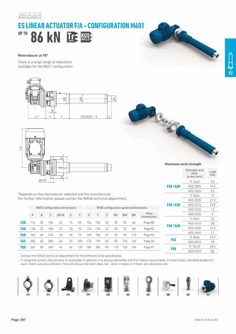
ES LINEAR ACTUATOR F/A - CONFIGURATION M601UP TO 86 kN TrTRAPEZ.
KGS
A C
BB
E
ØD f8
F Y COURSE + X Z
ØR
ØW
ØV
L2*
L1*
Motoreducer at 90º
There is a large range of reductions
available for the M601 configuration.
M601 configuration dimensions M100 configuration general dimensions
A B C ØD f8 E F X Y Z ØV ØW ØR More
dimensions
F20 116 20 156 20 15 55 106 100 36 35 55 66 Page 80
F30 138 25 188 25 20 70 124 130 37 50 75 88 Page 82
F40 160 40 240 35 30 75 155 150 67 70 90 110 Page 84
F45 200 40 280 40 35 105 175 195 65 90 115 140 Page 86
F50 260 50 360 45 40 130 185 300 95 110 150 196 Page 87
… Contact the NIASA technical department for the diAerent drive possibilities.
… If using ball screws, the actuator is reversible. In general, it is always advisable that the motors have brakes. In most cases, standard brakes for
each motor size are suHcient. This will ensure the stem does not when it stops or if there are vibrations, etc.
Diameter and pitch
screw (mm)
Load (kN)
F20 / A20
Tr 24x5 9.5
KGS 2005 10.5
KGS 2020 5.5
F30 / A30
Tr 36x6 15
KGS 3205 21.5
KGS 3210 23.5
KGS 3220 12
KGS 3240 6
F40 / A40
Tr 45x7 22
KGS 4010 38
KGS 4020 21.5
KGS 4040 11
F45Tr 50x8 47.5
KGS 5010 78
F50Tr 70x10 60.5
KGS 6310 86
Maximum axial strength
*Depends on the motoreducer selected and the manufacturer.
For further information, please contact the NIASA technical department.
272 273 276 278 280 281 282 300 307 312
BALLS
Page: 097

www.niasa.es
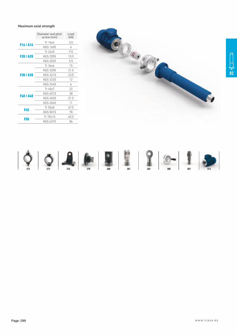
ES LINEAR ACTUATOR F/A - CONFIGURATION M605UP TO 86 kN TrTRAPEZ.
KGS
M205 configuration dimensions M100 configuration general dimensions
A B C ØD f8 E X Y Z ØV ØW ØR More dimensions
F16 82 15 112 15 12 84 61 36 32 40 45 Page 78
F20 116 20 156 20 15 106 100 36 35 55 66 Page 80
F30 138 25 188 25 20 124 130 37 50 75 88 Page 82
F40 160 40 240 35 30 155 150 67 70 90 110 Page 84
F45 200 40 280 40 35 175 195 65 90 115 140 Page 86
F50 260 50 360 45 40 185 300 95 110 150 196 Page 87
In line motor
There is a large range of reductions
available for the M605 configuration.
A C
BB
ØD
ØV
E
F L* Y COURSE + X Z
ØR
ØW
*Depends on the motor group selected and the manufacturer.
For further information, please contact the NIASA technical department
BALLS
Page: 098
www.niasa.es
02
Diameter and pitchscrew (mm)
Load (kN)
F16 / A16Tr 16x4 3.5
KGS 1605 6
F20 / A20
Tr 24x5 9.5
KGS 2005 10.5
KGS 2020 5.5
F30 / A30
Tr 36x6 15
KGS 3205 21.5
KGS 3210 23.5
KGS 3220 12
KGS 3240 6
F40 / A40
Tr 45x7 22
KGS 4010 38
KGS 4020 21.5
KGS 4040 11
F45Tr 50x8 47.5
KGS 5010 78
F50Tr 70x10 60.5
KGS 6310 86
Maximum axial strength
272 273 276 278 280 281 282 300 307 312
Page: 099

Linear actuators
DIMENSIONS AND WEIGHTS
Motorflange
(IEC type& size)
- - -
Trunnions Application1 Yes IN Indoor0 No
3) OU OutdoorSP Special category to ISO 12944
1) It includes coupling and fasteners to fix motor
2) Coupling key way according to DIN 6885
3) The motor bell is supplied with plastic cups to protect trunnions threaded holes
ACTUATORTYPE F
ACTUATORTYPE A
MATERIALS AND SURFACE TREATMENTS
Indoor applications 1)
Outdoor applications 2) 1)
Approx. C2-Medium durability (ISO 12944).Bell (aluminium): Anodizing (8~12 m) Anodizing (15~20 m) 2)
Approx. C3-Medium durability (ISO 12944).Fastenings: Black oxide coating Stainless steel Special coatings on request, until C5 (ISO 12944)
www.niasa.es
Linear
71 B14A
Motorflange
1
Type F Type A
MOTOR BELL AMBThe standard drive of Linear Actuators is made using asynchronous AC motors. The following table shows the available motor
flanges (IEC type and size) for each actuators size. For other types/sizes of motors, please contact NIASA. We can supply adapters
for any kind of electrical motor (AC single phase, AC with integrated inverter, DC, BLDC, stepper, …).
size Option (mm) (mm) (mm) (mm) (mm) (mm) (mm)
ACCESORIES
actuat. (kW) ØA ØB ØC D
Ensure motor is not overdimensioned for the selected linear actuator size. It may cause damage, or even breakage, of
it. For powers higher than the indicated ones in the next table, contact NIASA.
Linear Power
A B(mm) (mm) (mm)
F16
A16
56 B14A 0,06 0,09 80 65 4850 Ø5.5 9
71 B14A 0,25 0,37 105 85 7063 B14A 0,12 0,18 90 75 60 Ø5.5 11 50
14F20
A20
63 B14A 0,12 0,18 90 75 60 Ø5.571 B14A 0,25 0,37 105 85 70 Ø6.5
11
80 B14A 0,55 0,75 120 100 8071 B14A 0,25 0,37 105 85 70
Ø6.581 2
2,31019180 B14A 0,55 0,75 120 100 80 Ø6.5 19 192
90 B14A 1,1
224
19
160
7,345
6,9
30
135-294 -
90 B14A 1,1 1,5 160 115 95 Ø8.5 24
4,435
38260 364 - -
214
2840 50
160112 B14A100 B14A 2,2 3
160 B14A 11132 B14A 5,5 7,5 200 165 180 14,8
28
42
38
15 250
F30
F30
A30
Ø8.5951151401,51,190 B14A130 80 Ø6.5
Ø6.5
F40
A40
1,5 140 115
AMB
16032,2100 B14A
130 110 Ø8.5
32,2100 B14A
4
45,5 7,5
112 B14A
132 B14A
2004
200
215 180 Ø13
F45
130 110 Ø8.5
100
F50
80 B14A 0,55 0,75
130 Ø11
112 B14A165 130 Ø11
G(mm)
160 115 95 Ø8.5 28 35 200
14
Ø6.5 1412 15 82
ØF f8
24138
19
Ød 2) E
95 Ø8.5
24
2,7
1,8
118
G' H'
125
108 3,9
L1
(kg)
0,50,50,71,31,4
57
224 160
98 3,6
86
118
H(mm)
Weight
7173
actuat.size
IN-
Bell 1)
116 16020 100 144
9,5
13,5
20,3
15
85 121
125 17920 25
155
Page: 100

www.niasa.es
LINEAR ACTUATORS F SERIES: STEEL TUBE | A SERIES: ALUMINUM TUBE
PRODUCT SELECTIONTo select the correct F/A Series linear actuator, please follow this flow diagram.
If you would like to know the expected service life of a unit for your application, please
send the relevant data to the NIASA service department.
Page: 101

www.niasa.es
02
6 SIZE VALIDATION AND CONFIGURATION
CONFIRMATION
SIZE
RE-SIZING PROPOSAL
…
DESIGN VALIDATION (NIASA)
OVER-HEATINGBUCKLINGF F
RESONANCELATERAL
LOADS
F F F F
5 Page 104PLACING AN ORDER
PLACING AN ORDER
4 - Stem end- Input shaft- Lubrication- Corrosion protection- Sealing- Ambient temperature- ...
Page 260
Page 100
ADDITIONAL CONFIGURATION
ACCESSORIES
ADDITIONAL CONFIGURATION AND ACCESSORIES
3
Page 99
Page 74
INDEPENDENT ACTUATOR
STANDARD DRIVE
TORQUE AND POWER
CALCULATION
TORQUE AND POWER
CALCULATION
SPECIAL DRIVE
ACTUATOR SYSTEM
DRIVE TORQUE AND POWER CALCULATION
2SCREW TYPE REDUCTION
Page 78
Page 78
SCREW AND REDUCTION TYPE DEFINITION
APPLICATION1
M100 BASE CONFIGURATION
OTHER CONFIGURATION
SIZE PRE-SELECTION
Page 74
Page 74
Page 74
F/A ACTUATOR MODEL AND SIZE DEFINITION
BALL (KGS)
TRAPEZOIDAL (Tr)
SPECIAL
6 DESIGN VAL
BUCKLING
5 PLACING AN
4 ADDITIONALACCESSORIE
3 DRIVE TORQUECALCULATIO
Page: 102

www.niasa.es
STRENGTH AND TORQUE ACTING ON AN F/A SERIES LINEAR ACTUATOR
F Load to move at traction and/or compression.
FL Lateral load on the stem.
V Stem travel speed.
MD Torque on the input shaft.
n Speed on the input shaft.
LINEAR ACTUATORS F SERIES: STEEL TUBE | A SERIES: ALUMINUM TUBE
PRODUCT SELECTION
shaft.
shaft.
F
FL
MD
n
V
Page: 103

www.niasa.es
02
LINEAR ACTUATORS F SERIES: STEEL TUBE | A SERIES: ALUMINUM TUBE
PRODUCT SELECTION
After pre-selecting the suitable linear actuator for the
application, select the drive motor, following the steps below:
1. DRIVE TORQUE
2. A POWER REQUIRED
IMPORTANT
… In general, it is advisable to multiply the power value
calculated for a safety coeHcient of 1.3 to 2; the smaller the
installation the higher the coeHcient
… When the load to move is lower than 10% of the elevator's
nominal load, consider that value as the load to move.
3. START-UP TORQUE
In general, it must be calculated by multiplying the drive torque
by two.
DS Screw dynamic ePciency
Trapezoidal screw (Tr)
16 x 4 24 x 5 36 x 6 45 x 7 50 x 8 70 x 10
0.44 0.39 0.34 0.32 0.33 0.30
Ball screw (KGS)
0.9 (for all sizes)
TORQUE AND POWER OF A LINEAR ACTUATOR
MI Idle Torque
F16 / A16 F20 / A20 F30 / A30
Tr 16×4 0.38 Tr 24×5 0.52 Tr 36×6 1.6
KGS 1605 0.25 KGS 2005 0.42 KGS 3205 1.3
KGS 2020 0.48 KGS 3210 1.3
KGS 3220 1.3
KGS 3240 1.3
F40 / A40 F45 F50
Tr 45×7 1.9 Tr 50×8 2.1 Tr 70×10 2.1
KGS 4010 1.6 KGS 5010 1.7 KGS 6310 1.5
KGS 4020 1.7
KGS 4040 1.7
IMPORTANT
… The values indicated in the tables correspond to the
lubrication conditions established by NIASA and will be
reached after a small period of operation.
… In the case of low temperatures, these can be reduced
considerably.
MD Drive torque (Nm)
n Screw jack input speed (rpm)
PD (kW)=
MD Drive torque (kN)
F Load to move in dynamic (kN)
P Screw pitch (mm)
Mi Idle torque (Nm)
iR Input reduction, see for configurations M205, M501,
M505 and M601; i = 1 for M605 and M100
0.9 Cylinder dynamic eHciency
DS Screw dynamic eHciency
DR Reduction element dynamic eHciency:
- M205: DR
= 0,95 (coaxial reducer)
- M501: DR
= 0,97 (toothed strap)
- M505: DR
= 0,90 (90º bevel gearbox)
- M601: DR
, according to reduction (worm wheel and shaft)
- M605 and M100 = 1, without reducer
MD (Nm) = ( + M
i ) x
F x P
2 x π x 0,9 x DS
1
DR x i
R
MD x n
9550
Page: 104

www.niasa.es
LINEAR ACTUATORS F SERIES: STEEL TUBE | A SERIES: ALUMINUM TUBE
PRODUCT SELECTION
The following table shows the maximum transferrable torque
of a shaft and its keys. It is considered that the shaft is subject
exclusively to torsional forces.
IMPORTANT
… Never subject the input of a screw jack
to torque over that indicated for its shaft
and keys (see plans in the chapter “sizes”, page 74).
MAXIMUM TRANSFERABLE TORQUE ACCORDING TO SHAFT/ PARALLEL COTTER PIN (DIN 6885)
Shaft diameter Ø (mm)
Key dimensionsMaximum transferrable torque, M
D (Nm)
Key eiective length, L1 (mm)
b x h (mm)
t1 (mm)
t2 (mm)
10 16 20 28 40 50 70 100
8 – 10 3 x 3 1.8 1.4 5 9 12 - - - - -
10 – 12 4 x 4 2.5 1.8 9 13 17 - - - - -
12 – 17 5 x 5 3 2.3 15 24 30 42 - - - -
17 – 22 6 x 6 3.5 2.8 25 40 50 70 100 - - -
22 – 30 8 x 7 4 3.3 39 63 78 109 157 195 - -
30 – 38 10 x 8 5 3.3 50 82 102 143 204 255 357 -
38 – 44 12 x 8 5 3.3 62 98 123 173 247 308 432 -
Material: C45 (1.1191) according to EN 10083-1
Load type: Drive - Uniform /
Load - Light knocks
Assembly: tight
Cycles: >1,000,000
Safety factor: 1.5 - 2.5
IMPORTANT For other conditions, please
contact the NIASA technical department
b
t2
Ø
t1
h
L1
Page: 105

www.niasa.es
02
LINEAR ACTUATORS F SERIES: STEEL TUBE | A SERIES: ALUMINUM TUBE
PRODUCT SELECTION
The greasing interval depends on the type of work and its
cycle. Under normal conditions it is recommended to lubricate
every 800 - 2,000 hours of operation. It is important to avoid
over-lubricating.
A group lubricator is recommended for automatic lubrication,
which feeds the lubrication point. Depending on the type of
group lubricator, the lubrication may last up to two years.
NIASA supplies its actuators with the following type of
hydraulic lubricating mechanism:
… Straight lubricator DIN 71412 type A (Actuator F).
… Brass cap with O-ring (Actuator A).
… As a greasing nozzle for the nipples, the 515/G – 516/G
hydraulic connector is recommended.
For its protection and conservation, the use of plastic caps
is advised.
There is a possibility to supply F Series actuators with a brass
lubrication cap with an O-ring, and vice versa for A Series. See
the lubrication chapter in accessories.
The lineal actuator is supplied with G421 DIVINOL
LITHOGREASE for all applications with trapezoidal screws
and L152 KLUBER ISOFLEX TOPAS class 2, DIN51818 for ball
screws. For high speeds it is recommended to choose class 1
and heavy loads class 3.
A change of grease type may aAect the correct operation of the
equipment.
Specifications
A complete cleaning and change of grease is recommended
Lithium compound semi-synthetic greaseDIVINOL LITHOGREASE G421
Working temperature -35 to +160ºC
Density at 15ºC 0.9 kg/dm3
Cinematic viscosity (s/DIN 51 562)130 mm2/s at 40ºC 15 mm2/s at 100ºC
Dropping point (s/DIN ISO 2176) >220ºC
Water resistance (s/DIN 51 807/T1) Level 1
Synthetic hydrocarbon grease with lithium soapKLUBER ISOFLEX TOPAS L152
Working temperature -50 to +150ºC
Density at 20ºC 0.9 kg/dm3
Cinematic viscosity (s/DIN 51 562)100 mm2/s at 40ºC
14.5 mm2/s at 100ºC
Dropping point (s/DIN ISO 2176) >185ºC
Water resistance (s/DIN 51 807/T1) Level 1
A complete cleaning and change of grease is recommended after five years.
The greasing interval...
For further information, please contact the NIASA technical department.
LUBRICATION
Page: 106
www.niasa.es
LINEAR ACTUATORS F SERIES: STEEL TUBE | A SERIES: ALUMINUM TUBE
PRODUCT SELECTION
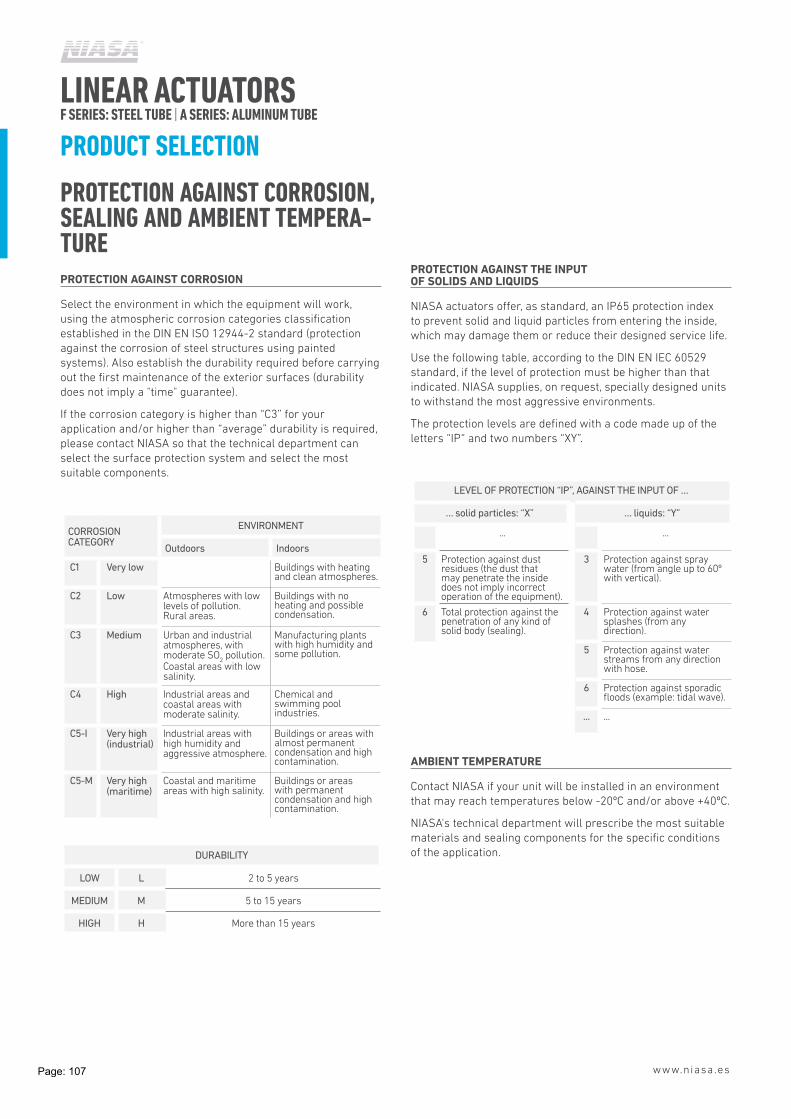
PROTECTION AGAINST CORROSION, SEALING AND AMBIENT TEMPERA-TUREPROTECTION AGAINST CORROSION
Select the environment in which the equipment will work,
using the atmospheric corrosion categories classification
established in the DIN EN ISO 12944-2 standard (protection
against the corrosion of steel structures using painted
systems). Also establish the durability required before carrying
out the first maintenance of the exterior surfaces (durability
does not imply a "time" guarantee).
If the corrosion category is higher than “C3” for your
application and/or higher than “average” durability is required,
please contact NIASA so that the technical department can
select the surface protection system and select the most
suitable components.
CORROSION CATEGORY
ENVIRONMENT
Outdoors Indoors
C1 Very low Buildings with heating and clean atmospheres.
C2 Low Atmospheres with low levels of pollution. Rural areas.
Buildings with no heating and possible condensation.
C3 Medium Urban and industrial atmospheres, with moderate SO
2 pollution.
Coastal areas with low salinity.
Manufacturing plants with high humidity and some pollution.
C4 High Industrial areas and coastal areas with moderate salinity.
Chemical and swimming pool industries.
C5-I Very high (industrial)
Industrial areas with high humidity and aggressive atmosphere.
Buildings or areas with almost permanent condensation and high contamination.
C5-M Very high(maritime)
Coastal and maritime areas with high salinity.
Buildings or areas with permanent condensation and high contamination.
DURABILITY
LOW L 2 to 5 years
MEDIUM M 5 to 15 years
HIGH H More than 15 years
PROTECTION AGAINST THE INPUT OF SOLIDS AND LIQUIDS
NIASA actuators oAer, as standard, an IP65 protection index
to prevent solid and liquid particles from entering the inside,
which may damage them or reduce their designed service life.
Use the following table, according to the DIN EN IEC 60529
standard, if the level of protection must be higher than that
indicated. NIASA supplies, on request, specially designed units
to withstand the most aggressive environments.
The protection levels are defined with a code made up of the
letters “IP“ and two numbers “XY”.
LEVEL OF PROTECTION “IP”, AGAINST THE INPUT OF …
… solid particles: “X” … liquids: “Y”
... ...
5 Protection against dust residues (the dust that may penetrate the inside does not imply incorrect operation of the equipment).
3 Protection against spray water (from angle up to 60º with vertical).
6 Total protection against the penetration of any kind of solid body (sealing).
4 Protection against water splashes (from any direction).
5 Protection against water streams from any direction with hose.
6 Protection against sporadic floods (example: tidal wave).
... ...
AMBIENT TEMPERATURE
Contact NIASA if your unit will be installed in an environment
that may reach temperatures below -20ºC and/or above +40ºC.
NIASA's technical department will prescribe the most suitable
materials and sealing components for the specific conditions
of the application.
Page: 107

www.niasa.es
02
LINEAR ACTUATORS F SERIES: STEEL TUBE | A SERIES: ALUMINUM TUBE
PRODUCT SELECTION
OPTIONAL CONFIGURATIONS
Optionally, NIASA may adapt your F/A actuator, modifying the
diAerent parts of it to your preferences.
Some examples are shown below.
See sub-section “Placing an order”.
Immobilizations
The F Series electro-mechanical actuators, on request, can
be supplied with the immobilized stem in rotation. This is
achieved by mounting a key on the upper cap and machining a
groove along the stem.
With this configuration, the scraper for the stem cannot be
mounted on the front cap. To avoid the possible entry of
particles or liquid through the stem, it is recommended to
mount a bellow to protect it.
For further information, please contact the NIASA technical
department.
Special configurations
At the customer's request, the linear actuators can be supplied
with a screw of several inputs so that higher speeds can be
obtained.
Front cap
cotter pin
screwsCotter pin
Groove
One input Two inputs Three inputs Four inputs
Page: 108

www.niasa.es
SIZE
F16 / A16
F20 / A20
F30 / A30
F40 / A40
F45
F50
CONFIGURATION
M100 Base
M205 In line motoreducer
M501 Parallel drive
M505 For drive at 90º
M601 Motoreducer at 90º
M605 In line motor
REDUCTION
Configuration M501
01 Reduction 1:1
02 Reduction 1:2
SR Special reduction
Configuration M205/M601
SR To be defined
Other configurations
00 No reduction
EQUIPMENT GENERAL PROTECTION
IPS Standard IP protection level
IPX Special IP protection level
SCREW TYPE (DIAMETER x PITCH)
TRS Trapezoidal
KGS Ball
STROKE
0000 Equipment usable stroke in mm
IMMOBILISATION IN ROTATION
00 No immobilization
01 Immobilized
01
02
03
05
07
04
06
Example 01 02 03 04 05
F30 M205 SR IPS KGS3205
LINEAR ACTUATORS F SERIES: STEEL TUBE | A SERIES: ALUMINUM TUBE
ORDER DESIGNATION
Page: 109

www.niasa.es
02
STEM FASTENING ACCESSORY
BPS Flange
GKS Single rod
GKB Double rod
GIR Ball joint
FES Special end fastening
000 No accessory
EXTERIOR TUBE FASTENING ACCESSORY
Actuator F
BB Trunnion mount with tipper studs
BH Trunnion mount with bearings
Actuator A
BA Trunnion mount
F/A Actuator
00 No accessory
TILT ACCESSORY
SB With tilt support
00 No tilt support
LIMIT SWITCH ACCESSORY
Actuator F
FCI Inductive limit switches
FCR Inductive limit switches with regulation
Actuator A
FCG Magnetic limit switches
F/A Actuator
000 No limit switches
STEM PROTECTION ACCESSORY
Actuator F
FB Bellow type protector
F/A Actuator
00 No protector
13
14
15
17
16
08
09
11
10
12
DRIVE ADAPTATION
Configuration M100/M505
VE Wheel
00 No adaptation
Configuration M205/M501/M601/M605
MK Default adaptation corresponding to
configuration
MS Special adaptation
00 No adaptation
MOTOR (ONLY IF CONFIGURATION M205/M501/M605)
MK drive adaptation
080 Group size
A Power-1 / B Power-2
MS drive adaptation
1111 Non-standard drive
Both adaptations
0000 Without drive
LUBRICANT
GRA Standard lubricant
GRX Lubricant for low extreme temperatures
GRS Other lubricant
LUBRICATION ACCESSORIES
ERT Straight lubricator (standard F Series)
ETP Sealed lubrication cap (standard A Series)
AGR Automatic lubricating accessory
000 Other lubricating accessory
EQUIPMENT GENERAL COLOUR
RAZ Blue RAL5017 (standard F Series)
RGG Graphite grey RAL7024
RGP Silver grey RAL9006
RSP Special colour indicated by the customer
CIP Only grey 411 priming
000 Not painted (standard A Series)
06 07 08 09 10 11 12 13 14 15 16 17
0300 00 BPS 00 SB FCI FB MK GR080A GRA ERT RAZ
Page: 110
www.niasa.es
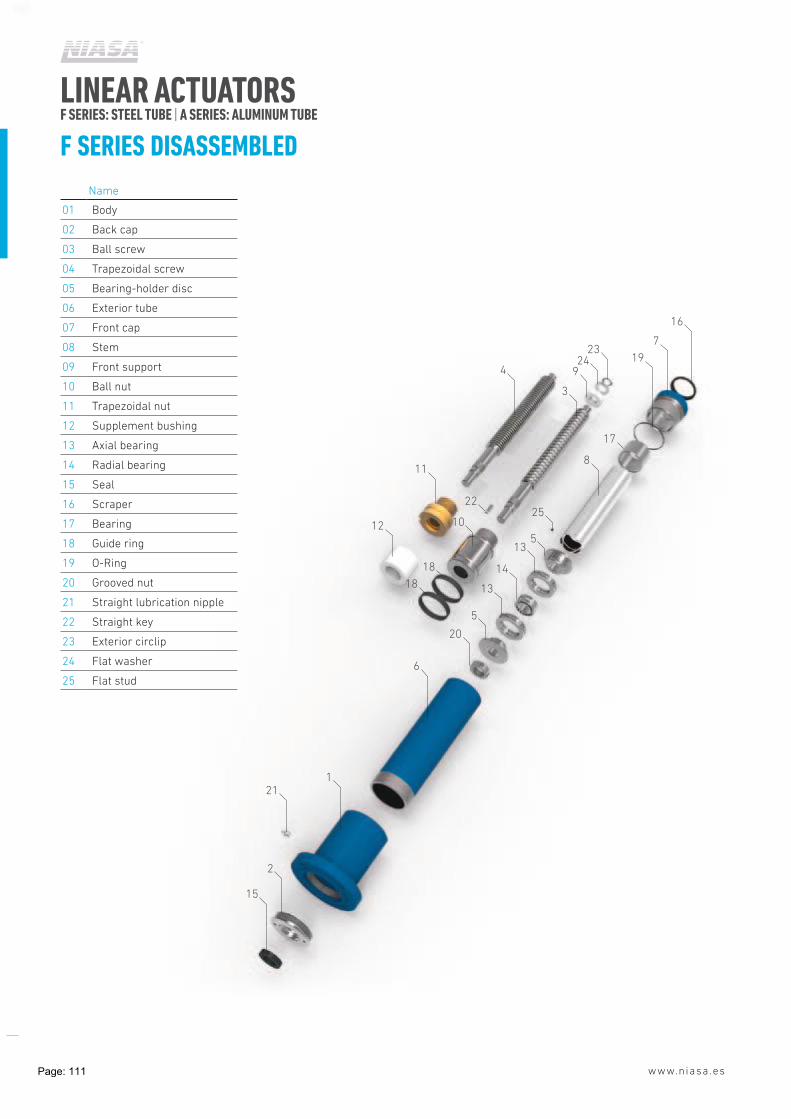
LINEAR ACTUATORS F SERIES: STEEL TUBE | A SERIES: ALUMINUM TUBE
F SERIES DISASSEMBLED
16
7
1923
249
17
8
5
25
13
18
18
10
22
12
11
4
3
14
13
5
20
6
1
2
21
15
Name
01 Body
02 Back cap
03 Ball screw
04 Trapezoidal screw
05 Bearing-holder disc
06 Exterior tube
07 Front cap
08 Stem
09 Front support
10 Ball nut
11 Trapezoidal nut
12 Supplement bushing
13 Axial bearing
14 Radial bearing
15 Seal
16 Scraper
17 Bearing
18 Guide ring
19 O-Ring
20 Grooved nut
21 Straight lubrication nipple
22 Straight key
23 Exterior circlip
24 Flat washer
25 Flat stud
Page: 111

www.niasa.es
02
LINEAR ACTUATORS F SERIES: STEEL TUBE | A SERIES: ALUMINUM TUBE
A SERIES DISASSEMBLED
www.niasa.es
29
21
4
31
3
15
23
14
1828
2
19
1718
14
16
25
6
27
247
8
10
119
12
13
12
20
15
5
22
30
1
26
Name
01 Exterior tube
02 Axial package support body
03 Posterior end carriage
04 Back cap
05 Front cap
06 Stem
07 Front support
08 Ball screw
09 Trapezoidal screw
10 Ball nut
11 Trapezoidal nut
12 Guide ring
13 Supplement bushing
14 Bearing-holder disc
15 Sealed joint
16 Profile closure band
17 Lubrication cap
18 Axial bearing
19 Radial bearing
20 Bearing
21 Seal
22 Scraper
23 Grooved nut
24 Flat washer
25 Exterior circlip
26 Straight key
27 Flat stud
28 Straight stud
29 Allen screw
30 Allen screw
31 O-Ring
Page: 112

LINEAR ACTUATORS F SERIES: STEEL TUBE | A SERIES: ALUMINUM TUBE
SPECIAL CONFIGURATIONS
Modified body for mounting
aluminum extrusion profile
with magnetic sensor.
Special flange adapted for
coupling with a torque limiter
Special trunnion
mounts adapted
to the customer's
requirement.
Special flange for
hydraulic motor
If the standard product range does not meet your requirements,
please contact NIASA for modification to any unit. With complete
safety, it will be adapted to your requirements.
Page: 113

www.niasa.es
02
www.niasa.es
02
Special flange for
coupling with a torque
limiter
Special flange adapted to
NEMA type servomotor
Special size stem
union adapted to
customer's accessory
Compact unit, just 5 mm
of safety margin
in both directions
Flange adapted to motor flange
defined by the customer.
Page: 114