f01u161691-05 isw-d8125cw-v2 inguide - bosch...
TRANSCRIPT
EN
Installation and Operation Guide
Inovonics Echostream Interface Module
ISW-D8125CW-V2
ISW-D8125CW-V2 | Installation and Operation Guide | Contents
2 Bosch Security Systems, Inc. | 8/11 | F01U161691-05
Contents 1.0 Overview...............................................................................................................................................................3 1.1 FCC Compliance Notice, Part 15.........................................................................................................................3 1.2 Features ...................................................................................................................................................................3 1.3 Specifications ..........................................................................................................................................................4 1.4 Power.......................................................................................................................................................................4 1.5 System Supervision ................................................................................................................................................4 1.6 ISW-D8125CW-V2 Back View ............................................................................................................................4 2.0 Installation.............................................................................................................................................................5 2.1 Configuring the Commercial Wireless Interface Module..................................................................................5 2.2 Mounting the Commercial Wireless Interface Module .....................................................................................5 2.3 Wiring the Commercial Wireless Interface Module to the Control Panel and EN4200 Serial Receiver ....6 3.0 Operation ..............................................................................................................................................................9 3.1 Commercial Wireless Interface Module Quick Startup Recommendations ...................................................9 3.2 Labeling the Bosch Transmitters ..........................................................................................................................9 3.3 Keypad Overview ..................................................................................................................................................9 3.4 Initial Power-up ....................................................................................................................................................10 3.5 RF System OK .....................................................................................................................................................10 3.6 Call for Service.....................................................................................................................................................10 3.7 Factory Default Passcode ....................................................................................................................................10 3.8 Entering Invalid Passcodes..................................................................................................................................10 3.9 Keypad Menus .....................................................................................................................................................11 3.10 Other Programming Functions...........................................................................................................................15 4.0 Troubleshooting.................................................................................................................................................17 4.1 Troubleshooting Solutions ..................................................................................................................................17 4.2 EN4200 Receiver Supervision ............................................................................................................................19 4.3 Missing RF Transmitters .....................................................................................................................................19 4.4 Low Transmitter Battery Conditions .................................................................................................................19 4.5 Commercial Wireless Interface Module Power Cycle Operation ..................................................................19 4.6 Frequently Asked Questions ...............................................................................................................................19 5.0 Program Record Sheet .....................................................................................................................................21
ISW-D8125CW-V2 | Installation and Operation Guide | Overview
.
Bosch Security Systems, Inc. | 8/11 | F01U161691-05 3
1.0 Overview The ISW-D8125CW-V2 is an integrated commercial wireless interface module and keypad. The keypad accesses the programming and diagnostic functions of the wireless portion of the system. The integrated keypad on the commercial wireless interface module looks different from the typical keypads (D1255, D1256, D1257, and so on) so that it is not mistaken for a system keypad.
The commercial wireless interface module must be mounted within 5 ft of the control panel. It is designed so that it is mounted right next to the D8103, D8108A or D8109 enclosure.
The commercial wireless interface module is compatible with the following control panels:
• GV3 Series: D9412GV3, D7412GV3, D7212GV3
• GV2 Series: D9412GV2, D7412GV2, D7212GV2
• G Series: D9412G, D7412G, D7212G*
• 9000 Series: D9412, D9112*, D7412, D7212*
* These control panels must have Firmware 6.5 or later installed (Firmware 6.51 or later for the D7212G).
All of the compatible control panels can have both hardwired (D8128D OctoPOPITS, D8125 Popex / D9127 POPITS, D8125MUX) and wireless points connected at the same time.
To add wireless points, an Inovonics Echostream EN4200 Serial Receiver must be connected to the commercial wireless interface module which is then connected to the control panel’s ZONEX 1 (and/or ZONEX 2) terminals and Aux Power. For best transmitter reception results, the EN4200 Serial Receiver should be centrally located among the transmitters. If transmitters are at too great of a distance for the EN4200 Receiver to pick up the transmission, install an EN5040-T RF Repeater.
1.1 FCC Compliance Notice, Part 15 This equipment has been tested and found to comply with the limits for a Class B digital device, pursuant to Part 15 of the FCC Rules. These limits are designed to provide reasonable protection against harmful interference in a commercial installation. This equipment generates, uses, and can radiate radio frequency energy, and, if not installed in accordance with the instructions, may cause harmful interference to radio communications. However, there is no guarantee that interference will not occur in a particular installation. If this equipment does cause harmful interference to radio or television reception, which can be determined by turning the equipment on and off, the user is encouraged to try to correct the interference by one or more of the following measures:
1. Reorient or relocate the receiving antenna.
2. Increase the separation between the equipment and the receiver.
3. Connect the equipment into an outlet on a circuit different from that to which the receiver is connected.
4. Consult the dealer or an experienced radio/TV technician for help.
1.2 Features • The commercial wireless interface module features
a menu-driven user interface.
• The commercial wireless interface module supports the following number of Bosch commercial wireless transmitters: - 234 transmitters (117 per bus) on the D9112
and all versions of the D9412 - 65 transmitters on all versions of the D7412 - 32 transmitters on all versions of the D7212
Points 74 and 75 on ZONEX 1 and Points 194 and 195 on ZONEX 2 cannot be used for any device other than the ISW-EN1224-ON Keyfob.
• The commercial wireless interface module provides diagnostic functions to troubleshoot RF transmitters.
• The commercial wireless interface module features a fixed device check-in time of 3 minutes.
• The commercial wireless interface module features a programmable system supervision interval.
ISW-D8125CW-V2 | Installation and Operation Guide | Overview
4 Bosch Security Systems, Inc. | 8/11 | F01U161691-05
1.3 Specifications
Table 1: Commercial Wireless Interface Module Specifications
Specification Value User Interface - LCD Display: 2 lines x 16
characters, backlit - Keypad: 0-9 numbers; ESC, ENT,
PREV, NEXT and DIAG keys Operating Voltage
10.2 - 14 VDC supplied by Aux Power from Control Panel or an External Auxiliary Power Supply.
Current 20 mA typical, 50 mA maximum plus ≈ 60 mA for each EN4200 receiver
Operating Temperature
+32°F to +149°F (0°C to +65°C), 93% Relative Humidity
Wiring 18 AWG or 22 AWG Solid or Stranded. Maximum distance from the control panel to the commercial wireless interface module cannot exceed 5 ft (1.5 m). Maximum distance from commercial wireless interface module to EN4200 cannot exceed 100 ft (33 m).
Dimensions (HxWxD)
3.94 in. x 6.5 in. x 1.2 in. (10 cm x 16.6 cm x 3 cm)
For UL Listed installations, install the commercial wireless interface module within 20 ft (6 m) of, and within the same room as, the EN4200 Serial Receiver.
1.4 Power If the commercial wireless interface module is powered down and then back up, it may take up to a maximum of 5 minutes (Check-In Time is fixed at 3 minutes) for all the transmitters to report back to the commercial wireless interface module with their current status.
In addition, when the commercial wireless interface module is powered up, all programmed RF points will report Normal until their state is updated.
The commercial wireless interface module’s power should be connected to the control panel using the Aux Power terminals. If the commercial wireless interface module were to lose power, the following conditions may result:
• All RF points will report to the control panel as missing (trouble/alarm).
• All RF points will initialize in a normal state when power is reapplied.
• Alarms initiated prior to power loss would be reset. If the alarm conditions persist when power is restored, new alarms would be generated.
Programmed settings such as RF point configuration will remain intact upon the event of a power loss.
1.5 System Supervision
1.5.1 Watchdog
The commercial wireless interface module implements a watchdog software. Failure of the program will result in a software reset within two seconds. This may cause a trouble condition on the control panel for the duration of the reset.
1.5.2 Self-Testing
The commercial wireless interface module EEPROM memory is automatically tested on a periodic basis. The EEPROM checksum is verified every ten minutes. If the EEPROM checksum fails, a point bus trouble condition will be seen at the control panel.
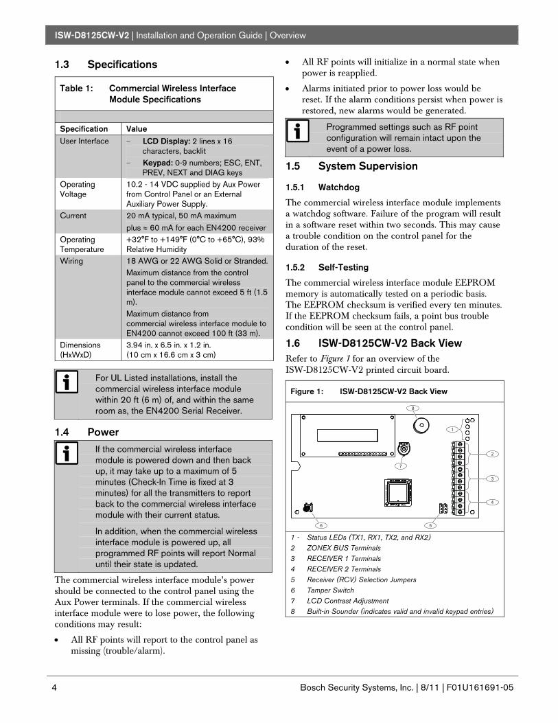
1.6 ISW-D8125CW-V2 Back View Refer to Figure 1 for an overview of the ISW-D8125CW-V2 printed circuit board.
Figure 1: ISW-D8125CW-V2 Back View
�
�
�
�
��
�
1 - Status LEDs (TX1, RX1, TX2, and RX2) 2 ZONEX BUS Terminals 3 RECEIVER 1 Terminals 4 RECEIVER 2 Terminals 5 Receiver (RCV) Selection Jumpers 6 Tamper Switch 7 LCD Contrast Adjustment 8 Built-in Sounder (indicates valid and invalid keypad entries)
ISW-D8125CW-V2 | Installation and Operation Guide | Installation
.
Bosch Security Systems, Inc. | 8/11 | F01U161691-05 5
2.0 Installation The commercial wireless interface module is packaged with a Point Label Sheet. Save these, as you will use them when identifying the point numbers on the Bosch transmitters.
2.1 Configuring the Commercial Wireless Interface Module
2.1.1 Register (REG) Pins
By default, the commercial wireless interface module is configured to register RF transmitters with a single press of the transmitter’s reset button.
You can also configure the commercial wireless interface module to require two presses of the RF transmitter’s reset button to register the RF transmitter.
Refer to Figure 2 to set the REG pins.
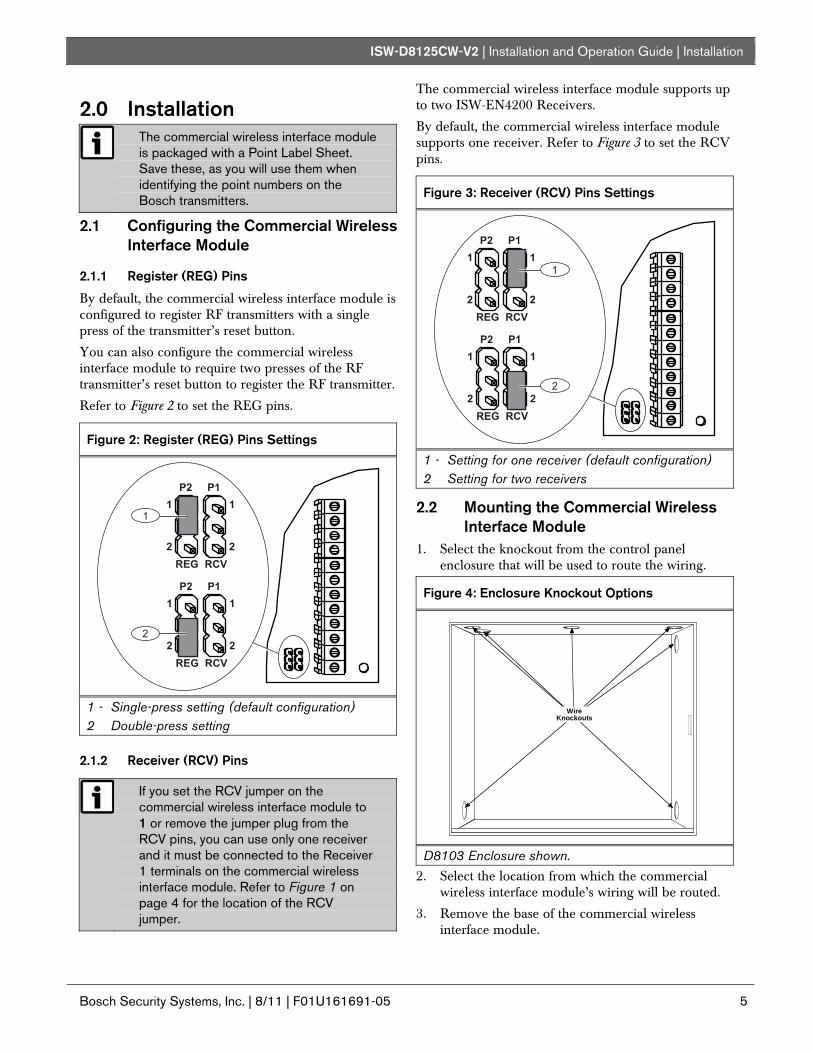
Figure 2: Register (REG) Pins Settings
��� ���
� �
� �
��
�
��� ���
� �
� �
��
�
1 - Single-press setting (default configuration) 2 Double-press setting
2.1.2 Receiver (RCV) Pins
If you set the RCV jumper on the commercial wireless interface module to 1 or remove the jumper plug from the RCV pins, you can use only one receiver and it must be connected to the Receiver 1 terminals on the commercial wireless interface module. Refer to Figure 1 on page 4 for the location of the RCV jumper.
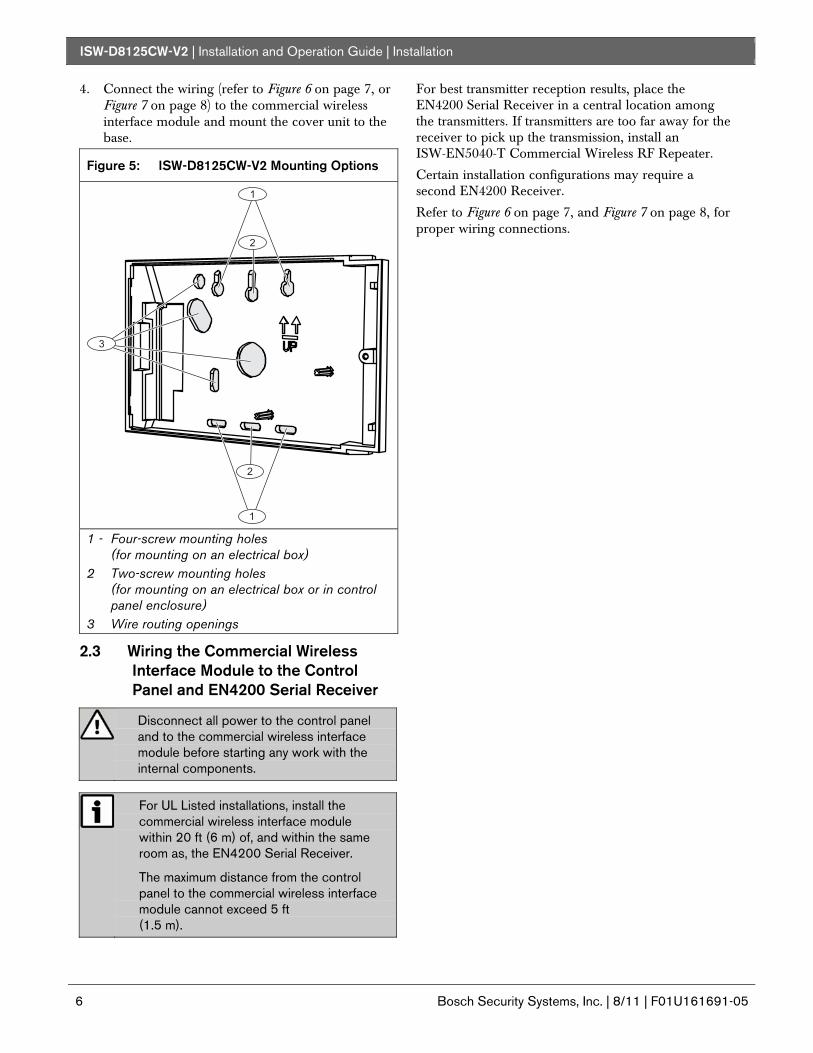
The commercial wireless interface module supports up to two ISW-EN4200 Receivers.
By default, the commercial wireless interface module supports one receiver. Refer to Figure 3 to set the RCV pins.
Figure 3: Receiver (RCV) Pins Settings
��� ���
� �
� �
��
�
��� ���
� �
� �
��
�
1 - Setting for one receiver (default configuration) 2 Setting for two receivers
2.2 Mounting the Commercial Wireless Interface Module
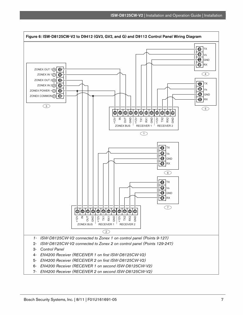
1. Select the knockout from the control panel enclosure that will be used to route the wiring.
Figure 4: Enclosure Knockout Options
WireKnockouts
D8103 Enclosure shown.
2. Select the location from which the commercial wireless interface module’s wiring will be routed.
3. Remove the base of the commercial wireless interface module.
ISW-D8125CW-V2 | Installation and Operation Guide | Installation
6 Bosch Security Systems, Inc. | 8/11 | F01U161691-05
4. Connect the wiring (refer to Figure 6 on page 7, or Figure 7 on page 8) to the commercial wireless interface module and mount the cover unit to the base.
Figure 5: ISW-D8125CW-V2 Mounting Options
�
�
�
�
�
1 - Four-screw mounting holes (for mounting on an electrical box)
2 Two-screw mounting holes (for mounting on an electrical box or in control panel enclosure)
3 Wire routing openings
2.3 Wiring the Commercial Wireless Interface Module to the Control Panel and EN4200 Serial Receiver
Disconnect all power to the control panel and to the commercial wireless interface module before starting any work with the internal components.
For UL Listed installations, install the commercial wireless interface module within 20 ft (6 m) of, and within the same room as, the EN4200 Serial Receiver.
The maximum distance from the control panel to the commercial wireless interface module cannot exceed 5 ft (1.5 m).
For best transmitter reception results, place the EN4200 Serial Receiver in a central location among the transmitters. If transmitters are too far away for the receiver to pick up the transmission, install an ISW-EN5040-T Commercial Wireless RF Repeater.
Certain installation configurations may require a second EN4200 Receiver.
Refer to Figure 6 on page 7, and Figure 7 on page 8, for proper wiring connections.
ISW-D8125CW-V2 | Installation and Operation Guide | Installation
.
Bosch Security Systems, Inc. | 8/11 | F01U161691-05 7
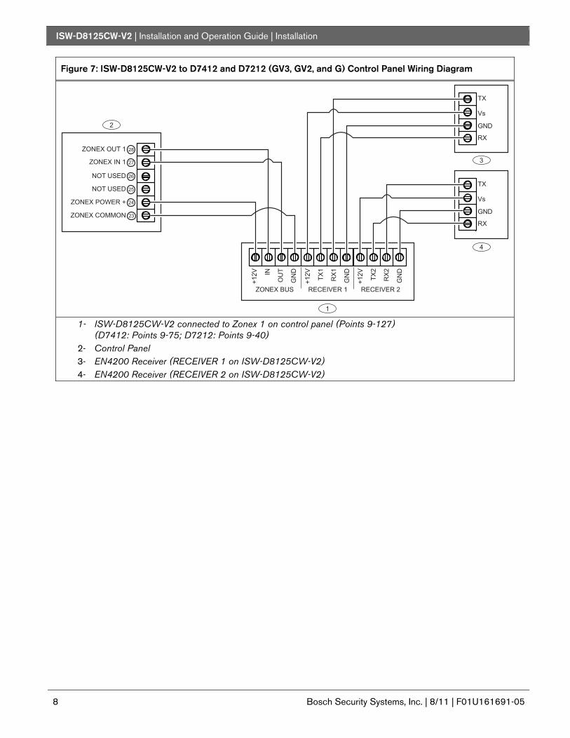
Figure 6: ISW-D8125CW-V2 to D9412 (GV3, GV2, and G) and D9112 Control Panel Wiring Diagram
�� �������
�� ������
�� ����� ���
�� �������� ��
��
��
��
��
��� �������
�� ������
�� ����� � � �� ���� � �� ���
����
��
�
��
�
��
�
���� ��
��
�
��
�
����
��
�
��
�
��
�
��
���
��
��
�� ����� � � �� ���� � �� ���
����
��
�
��
�
��
�
���� ��
��
�
��
�
����
��
�
��
�
��
�
��
���
��
��
��
���
��
��
�
�
�
�
�
�
�
��
���
��
��
1- ISW-D8125CW-V2 connected to Zonex 1 on control panel (Points 9-127) 2- ISW-D8125CW-V2 connected to Zonex 2 on control panel (Points 129-247) 3- Control Panel 4- EN4200 Receiver (RECEIVER 1 on first ISW-D8125CW-V2) 5- EN4200 Receiver (RECEIVER 2 on first ISW-D8125CW-V2) 6- EN4200 Receiver (RECEIVER 1 on second ISW-D8125CW-V2) 7- EN4200 Receiver (RECEIVER 2 on second ISW-D8125CW-V2)
ISW-D8125CW-V2 | Installation and Operation Guide | Installation
8 Bosch Security Systems, Inc. | 8/11 | F01U161691-05
Figure 7: ISW-D8125CW-V2 to D7412 and D7212 (GV3, GV2, and G) Control Panel Wiring Diagram
�� ����� � � �� ���� � �� ���
����
��
�
��
�
��
�
���� ��
��
�
��
�
����
��
�
��
�
��
�
��
���
��
��
��
���
��
��
�
�
�
�
������ �
������ �
�� ����� ���
�� �������� ��
��
��
��
��
��� �������
�� ������
1- ISW-D8125CW-V2 connected to Zonex 1 on control panel (Points 9-127) (D7412: Points 9-75; D7212: Points 9-40)
2- Control Panel 3- EN4200 Receiver (RECEIVER 1 on ISW-D8125CW-V2) 4- EN4200 Receiver (RECEIVER 2 on ISW-D8125CW-V2)
ISW-D8125CW-V2 | Installation and Operation Guide | Operation
.
Bosch Security Systems, Inc. | 8/11 | F01U161691-05 9
3.0 Operation 3.1 Commercial Wireless Interface
Module Quick Startup Recommendations
The following information details the recommended programming steps that should be taken when installing a commercial wireless interface module in a new installation.
1. Press the [2] key and change the Installer Passcode, if necessary. Refer to Section 3.9.6 Changing the Installer Passcode on page 13.
If you lose or forget the Installer Passcode, you must send the commercial wireless interface module in for repair to reset the Installer Passcode. The default passcode is 123456.
2. Press the [1] key to add RF Transmitters to the system. Refer to Section 3.9.1 Add or Edit an RF Transmitter on page 11).
3. Press the [DIAG] key to test the system during and after installation.
3.2 Labeling the Bosch Transmitters Prior to programming the Bosch transmitters or commercial wireless interface module, it is recommended that you take the time now to apply the point number labels from the Point Label Sheet to the individual transmitters.
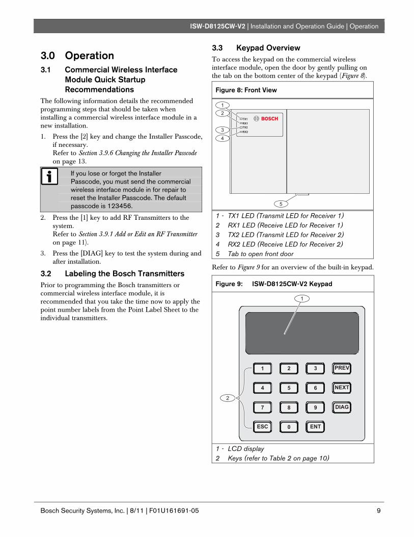
3.3 Keypad Overview To access the keypad on the commercial wireless interface module, open the door by gently pulling on the tab on the bottom center of the keypad (Figure 8).
Figure 8: Front View
��
�����
���
�
�
�
�
�
1 - TX1 LED (Transmit LED for Receiver 1) 2 RX1 LED (Receive LED for Receiver 1) 3 TX2 LED (Transmit LED for Receiver 2) 4 RX2 LED (Receive LED for Receiver 2) 5 Tab to open front door
Refer to Figure 9 for an overview of the built-in keypad.
Figure 9: ISW-D8125CW-V2 Keypad
� ���
� ��
���
�����
� �
� � �
� � �
�
�
�
1 - LCD display 2 Keys (refer to Table 2 on page 10)
ISW-D8125CW-V2 | Installation and Operation Guide | Operation
10 Bosch Security Systems, Inc. | 8/11 | F01U161691-05
Table 2: Key Descriptions
Key Description ESC Escape: Backs out of a programming option
or menu level. ENT Enter: Accepts a program entry. PREV Manually scrolls to a previous menu or point
selection. This key also stops the auto-scrolling of the menus.
NEXT Manually scrolls to the next menu or point selection. This key also stops the auto-scrolling of the menus.
DIAG Shortcut to RF Diagnostics menu (see Section 3.9.9 RF on page 14).
A single beep indicates entry is acknowledged. Two beeps indicate valid entry. Three beep tones indicate an input error was made.
3.4 Initial Power-up When the commercial wireless interface module is powered, it displays the idle text (Figure 10, Figure 11 or Figure 12).
• Figure 10 appears if no transmitters are programmed into the commercial wireless interface module.
• Figure 11 appears if one or more transmitters are already programmed in the commercial wireless interface module and are not missing.
• Figure 12 appears if the commercial wireless interface module has a system fault.
Figure 10: System Defaulted Display
3.5 RF System OK If the system is OK, the keypad shows Figure 11.
Figure 11: RF System Normal
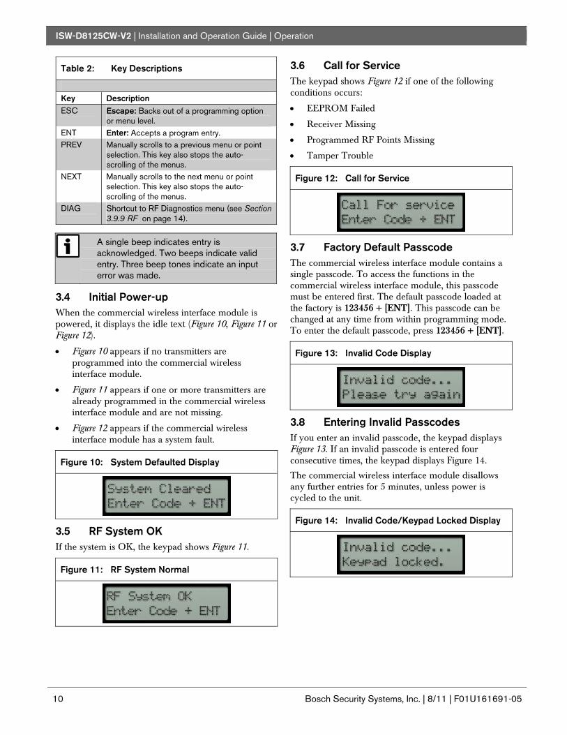
3.6 Call for Service The keypad shows Figure 12 if one of the following conditions occurs:
• EEPROM Failed
• Receiver Missing
• Programmed RF Points Missing
• Tamper Trouble
Figure 12: Call for Service
3.7 Factory Default Passcode The commercial wireless interface module contains a single passcode. To access the functions in the commercial wireless interface module, this passcode must be entered first. The default passcode loaded at the factory is 123456 + [ENT]. This passcode can be changed at any time from within programming mode. To enter the default passcode, press 123456 + [ENT].
Figure 13: Invalid Code Display
3.8 Entering Invalid Passcodes If you enter an invalid passcode, the keypad displays Figure 13. If an invalid passcode is entered four consecutive times, the keypad displays Figure 14.
The commercial wireless interface module disallows any further entries for 5 minutes, unless power is cycled to the unit.
Figure 14: Invalid Code/Keypad Locked Display
ISW-D8125CW-V2 | Installation and Operation Guide | Operation
.
Bosch Security Systems, Inc. | 8/11 | F01U161691-05 11
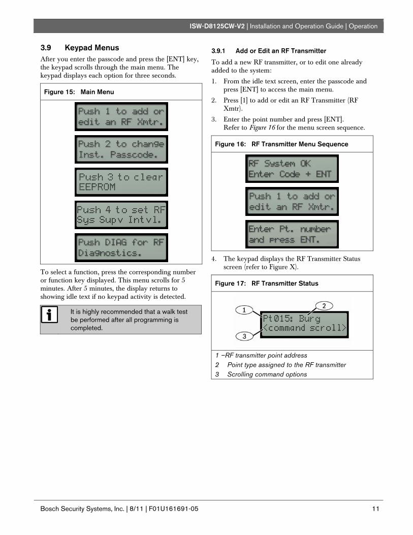
3.9 Keypad Menus After you enter the passcode and press the [ENT] key, the keypad scrolls through the main menu. The keypad displays each option for three seconds.
Figure 15: Main Menu
To select a function, press the corresponding number or function key displayed. This menu scrolls for 5 minutes. After 5 minutes, the display returns to showing idle text if no keypad activity is detected.
It is highly recommended that a walk test be performed after all programming is completed.
3.9.1 Add or Edit an RF Transmitter
To add a new RF transmitter, or to edit one already added to the system:
1. From the idle text screen, enter the passcode and press [ENT] to access the main menu.
2. Press [1] to add or edit an RF Transmitter (RF Xmtr).
3. Enter the point number and press [ENT]. Refer to Figure 16 for the menu screen sequence.
Figure 16: RF Transmitter Menu Sequence
4. The keypad displays the RF Transmitter Status screen (refer to Figure X).
Figure 17: RF Transmitter Status
1 –RF transmitter point address 2 Point type assigned to the RF transmitter 3 Scrolling command options
ISW-D8125CW-V2 | Installation and Operation Guide | Operation
12 Bosch Security Systems, Inc. | 8/11 | F01U161691-05
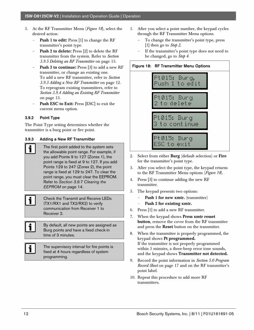
5. At the RF Transmitter Menu (Figure 18), select the desired action:
- Push 1 to edit: Press [1] to change the RF transmitter’s point type.
- Push 2 to delete: Press [2] to delete the RF transmitter from the system. Refer to Section 3.9.5 Deleting an RF Transmitter on page 13.
- Push 3 to continue: Press [3] to add a new RF transmitter, or change an existing one. To add a new RF transmitter, refer to Section 3.9.3 Adding a New RF Transmitter on page 12. To reprogram existing transmitters, refer to Section 3.9.4 Adding an Existing RF Transmitter on page 13.
- Push ESC to Exit: Press [ESC] to exit the current menu option.
3.9.2 Point Type
The Point Type setting determines whether the transmitter is a burg point or fire point.
3.9.3 Adding a New RF Transmitter
The first point added to the system sets the allowable point range. For example, if you add Points 9 to 127 (Zonex 1), the point range is fixed at 9 to 127. If you add Points 129 to 247 (Zonex 2), the point range is fixed at 129 to 247. To clear the point range, you must clear the EEPROM. Refer to Section 3.9.7 Clearing the EEPROM on page 14.
Check the Transmit and Receive LEDs (TX1/RX1 and TX2/RX2) to verify communication from Receiver 1 to Receiver 2.
By default, all new points are assigned as Burg points and have a fixed check-in time of 3 minutes.
The supervisory interval for fire points is fixed at 4 hours regardless of system programming.
1. After you select a point number, the keypad cycles through the RF Transmitter Menu options. - To change the transmitter’s point type, press
[1] then go to Step 2. - If the transmitter’s point type does not need to
be changed, go to Step 4.
Figure 18: RF Transmitter Menu Options
2. Select from either Burg (default selection) or Fire for the transmitter’s point type.
3. After you select the point type, the keypad returns to the RF Transmitter Menu options (Figure 18).
4. Press [3] to continue adding the new RF transmitter.
5. The keypad presents two options:
- Push 1 for new xmtr. (transmitter) - Push 2 for existing xmtr.
6. Press [1] to add a new RF transmitter.
7. When the keypad shows Press xmtr resset button, remove the cover from the RF transmitter and press the Reset button on the transmitter.
8. When the transmitter is properly programmed, the keypad shows Pt programmed. If the transmitter is not properly programmed within 5 minutes, a three-beep error tone sounds, and the keypad shows Transmitter not detected.
9. Record the point information in Section 5.0 Program Record Sheet on page 17 and on the RF transmitter’s point label.
10. Repeat this procedure to add more RF transmitters.
ISW-D8125CW-V2 | Installation and Operation Guide | Operation
.
Bosch Security Systems, Inc. | 8/11 | F01U161691-05 13
3.9.4 Adding an Existing RF Transmitter
It may be necessary to add an already installed transmitter again to the commercial wireless interface module, especially if the transmitter was deleted using the RF Transmitter menu option (refer to Section 3.9.1 Add or Edit an RF Transmitter on page 11). In this case, the RF transmitters can be re-added to the commercial wireless interface module.
If you need to change the point type of an existing RF transmitter, program the transmitter is if it were a new transmitter. Refer to Section 3.9.3 Adding a New RF Transmitter on page 12.
Refer to Section 5.0 Program Record Sheet on page 17 for point types when replacing an RF transmitter or the commercial wireless interface module.
To add an existing RF transmitter:
1. Follow the steps in Section 3.9.1 Add or Edit an RF Transmitter on page 11 to reach the RF Transmitter status display (Figure 17 on page 11).
2. After you select a point number, the keypad cycles through the following displays. Refer to Figure 18 on page 12.
3. Press [3] to continue adding the RF transmitter.
4. The keypad presents two options:
- Push 1 for new xmtr. (transmitter) - Push 2 for existing xmtr.
5. Press [2] for an existing RF transmitter.
6. The keypad shows Ptxxx added. xxx = the RF transmitter’s point number. The point number of the RF transmitter is automatically incremented.
7. Record the point information in Section 5.0 Program Record Sheet on page 17 and on the RF transmitter’s point label.
8. Repeat this procedure to re-add other RF transmitters.
3.9.5 Deleting an RF Transmitter
To delete an RF transmitter:
1. Follow the steps in Section 3.9.1 Add or Edit an RF Transmitter on page 11 to reach the RF Transmitter status display (Figure 17 on page 11).
2. After you select a point number, the keypad cycles through the following displays. Refer to Figure 18 on page 12.
3. Press [2] to delete the RF transmitter.
4. The keypad beeps twice and shows Ptxxx deleted to indicate that the RF transmitter was deleted. xxx = the RF transmitter’s point number. The point number of the RF transmitter is automatically incremented.
5. In Section 4.0 Troubleshooting on page 17, indicate which RF transmitter was deleted.
6. Repeat this procedure to delete other RF transmitters.
3.9.6 Changing the Installer Passcode
If you lose or forget the Installer Passcode, you must send the commercial wireless interface module in for repair to reset the Installer Passcode.
By default, the Installer Passcode is 123456. To change the Installer Passcode:
1. From the main menu (Figure 15 on page 11), press [2]. The keypad shows Enter existing passcode:******.
2. Enter the current passcode. If you incorrectly enter the passcode, a three-beep error tone sounds, and the keypad shows Invalid code... The keypad then returns to the main menu.
3. After entering a valid passcode, the keypad shows Enter new passcode:******. Enter a new six-digit passcode.
4. The keypad prompts you to re-enter the new passcode. Enter it again.
5. If both entries match, the keypad shows Passcode changed. If you incorrectly enter the passcode, a three-beep error tone sounds, and the keypad shows Invalid code... The keypad then returns to the main menu.
6. To exit the Installer Passcode menu, press [ESC].
ISW-D8125CW-V2 | Installation and Operation Guide | Operation
14 Bosch Security Systems, Inc. | 8/11 | F01U161691-05
3.9.7 Clearing the EEPROM
Clearing the EEPROM erases the entire point database and resets the commercial wireless interface module to the factory default settings. Ensure that you have a printed copy of the programming settings so you can manually restore them after clearing the EEPROM.
If the data in the commercial wireless interface module has become corrupted and you need to reprogram the commercial wireless interface module, you need to first clear the EEPROM.
1. From the main menu (Figure 15 on page 11), press [3]. The keypad shows the following series of messages:
Clearing EEPROM erases all info!
Push ENT to clear EEPROM.
Push ESC to exit.
Push ENT again to confirm.
2. Press the [ENT] key twice to erase the EEPROM.
3.9.8 Setting the RF System Supervision Interval
The RF System Supervision Interval determines how long the commercial wireless interface module waits to hear at least one check-in transmission (or any transmission) from a transmitter before sending a Missing event to the Control Panel.
The interval value that is chosen applies to all burg point type transmitters system wide. The supervision interval for fire points remains fixed at 4 hours.
To set the RF System Supervision Interval:
1. From the main menu (Figure 15 on page 11), press [5].
2. Select one of the available options: - No supervision (Press [1] + [ENT]) - 4 hours (Press [2] + [ENT]) - 12 hours (Press [3] + [ENT]) - 24 hours (Press [4] + [ENT])
3. The keypad displays the new supervision interval setting for two seconds.
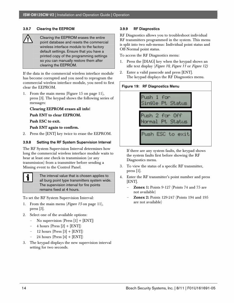
3.9.9 RF Diagnostics
RF Diagnostics allows you to troubleshoot individual RF transmitters programmed in the system. This menu is split into two sub-menus: Individual point status and Off-Normal point status.
To access the RF Diagnostics menu:
1. Press the [DIAG] key when the keypad shows an idle text display (Figure 10, Figure 11 or Figure 12)
2. Enter a valid passcode and press [ENT]. The keypad displays the RF Diagnostics menu.
Figure 19: RF Diagnostics Menu
If there are any system faults, the keypad shows the system faults first before showing the RF Diagnostics menu.
3. To view the status of a specific RF transmitter, press [1].
4. Enter the RF transmitter’s point number and press [ENT].
- Zonex 1: Points 9-127 (Points 74 and 75 are not available)
- Zonex 2: Points 129-247 (Points 194 and 195 are not available)
ISW-D8125CW-V2 | Installation and Operation Guide | Operation
.
Bosch Security Systems, Inc. | 8/11 | F01U161691-05 15
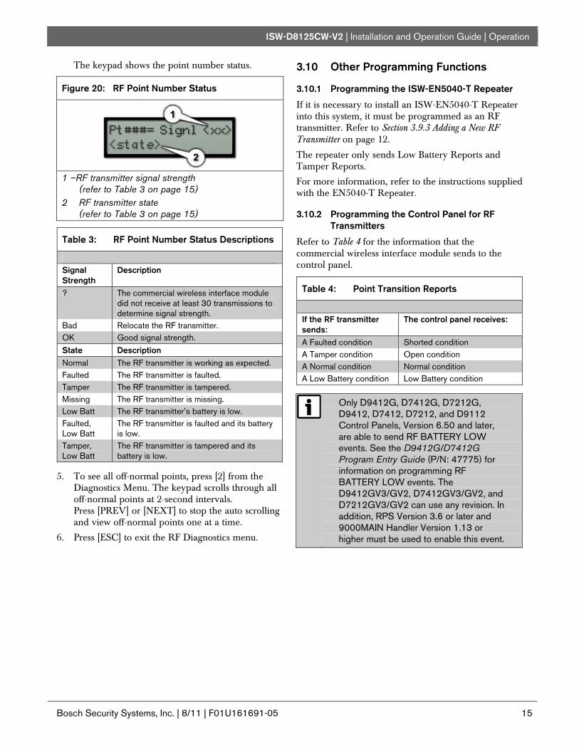
The keypad shows the point number status.
Figure 20: RF Point Number Status
1 –RF transmitter signal strength
(refer to Table 3 on page 15) 2 RF transmitter state
(refer to Table 3 on page 15)
Table 3: RF Point Number Status Descriptions
Signal Strength
Description
? The commercial wireless interface module did not receive at least 30 transmissions to determine signal strength.
Bad Relocate the RF transmitter. OK Good signal strength.
State Description Normal The RF transmitter is working as expected. Faulted The RF transmitter is faulted. Tamper The RF transmitter is tampered. Missing The RF transmitter is missing. Low Batt The RF transmitter’s battery is low. Faulted, Low Batt
The RF transmitter is faulted and its battery is low.
Tamper, Low Batt
The RF transmitter is tampered and its battery is low.
5. To see all off-normal points, press [2] from the Diagnostics Menu. The keypad scrolls through all off-normal points at 2-second intervals. Press [PREV] or [NEXT] to stop the auto scrolling and view off-normal points one at a time.
6. Press [ESC] to exit the RF Diagnostics menu.
3.10 Other Programming Functions
3.10.1 Programming the ISW-EN5040-T Repeater
If it is necessary to install an ISW-EN5040-T Repeater into this system, it must be programmed as an RF transmitter. Refer to Section 3.9.3 Adding a New RF Transmitter on page 12.
The repeater only sends Low Battery Reports and Tamper Reports.
For more information, refer to the instructions supplied with the EN5040-T Repeater.
3.10.2 Programming the Control Panel for RF Transmitters
Refer to Table 4 for the information that the commercial wireless interface module sends to the control panel.
Table 4: Point Transition Reports
If the RF transmitter sends:
The control panel receives:
A Faulted condition Shorted condition A Tamper condition Open condition A Normal condition Normal condition A Low Battery condition Low Battery condition
Only D9412G, D7412G, D7212G, D9412, D7412, D7212, and D9112 Control Panels, Version 6.50 and later, are able to send RF BATTERY LOW events. See the D9412G/D7412G Program Entry Guide (P/N: 47775) for information on programming RF BATTERY LOW events. The D9412GV3/GV2, D7412GV3/GV2, and D7212GV3/GV2 can use any revision. In addition, RPS Version 3.6 or later and 9000MAIN Handler Version 1.13 or higher must be used to enable this event.
ISW-D8125CW-V2 | Installation and Operation Guide | Operation
16 Bosch Security Systems, Inc. | 8/11 | F01U161691-05
If both a Tamper and Fault condition occur, the Tamper condition takes priority over the Fault condition and an open condition is sent to the control panel.
Therefore, Bosch Security Systems, Inc. recommends the following:
- Controlled points be programmed as ‘Instant alarm on Open’ when armed and ‘Trouble’ when disarmed.
- 24 Hour points be programmed as ‘Instant alarm on Open’.
- Fire points be programmed as ‘Trouble on Open’.
- An Open condition on the control panel signifies a Tamper while a Short condition is considered a Fault.
3.10.3 Programming the EN1224-ON Keyfob
Only one EN1224-ON Keyfob can be added per commercial wireless interface module. If more than one system is installed, such as one each on Zonex Bus 1 and Zonex Bus 2, an equal number of Keyfobs can be added. The ISW-D8125CW-V2 does not supervise Low Battery or Missing conditions for any of the keyfobs. The EN1224-ON Keyfob is treated as a maintained keyswitch on the GV3, GV2, and G Series Control Panels, and D9112 Control Panels. Set the keyfob’s point index to Point Type 4, Response 2.
When using the keyfob, Points 74 and 75 (for Zonex Bus 1 on GV3, GV2, and G Series Control Panels, and D9112* Control Panels) and Points 194 and 195 (for Zonex Bus 2 on D9412GV3/GV2, D9412G, D9412, and D9112 Control Panels) are used.
* The D9112 Control Panel requires firmware version 6.3 or later to work with Bosch Commercial Wireless products.
Do not program any other transmitters for Points 74 and 75 or Points 194 and 195. These are for the ISW-EN1224-ON Keyfobs only.
The EN1224-ON Keyfob has four buttons: ON, OFF, and two Alert (*) buttons. The ON button is used to arm the area the point is assigned to and initiate the Master Arm Delay state. The OFF button is used to disarm the area to which the point is assigned.
When both Alert buttons are pressed, the commercial wireless interface module sends a short to the control panel for Point 75 or 195. Program the control panel accordingly so that the Point Response provides the appropriate response. To clear the condition from Point 75 or 195, press the ON or OFF button on the keyfob.
To program an EN1224-ON Keyfob, program the lower-numbered point (74 or 194) as a new transmitter, and program the higher-numbered point (75 or 195) into the commercial wireless interface module as an existing transmitter. This will enable both points on the keyfob.
ISW-D8125CW-V2 | Installation and Operation Guide | Troubleshooting
.
Bosch Security Systems, Inc. | 8/11 | F01U161691-05 17
4.0 Troubleshooting 4.1 Troubleshooting Solutions
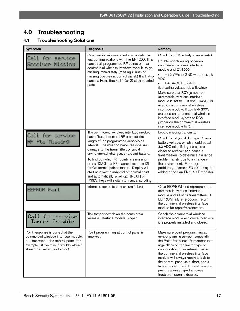
Symptom Diagnosis Remedy
Commercial wireless interface module has lost communications with the EN4200. This causes all programmed RF points on that commercial wireless interface module to go missing immediately (missing alarms or missing troubles at control panel.) It will also cause a Point Bus Fail 1 (or 2) at the control panel.
Check for LED activity at receiver(s).
Double-check wiring between commercial wireless interface module and EN4200. • +12 V/Vs to GND = approx. 13 VDC • DATA/OUT to GND = fluctuating voltage (data flowing) Make sure that RCV jumper on commercial wireless interface module is set to '1' if one EN4200 is used on a commercial wireless interface module; If two EN4200's are used on a commercial wireless interface module, set the RCV jumper on the commercial wireless interface module to '2'.
The commercial wireless interface module hasn't 'heard' from an RF point for the length of the programmed supervision interval. The most common reasons are damage to the transmitter, physical environmental changes, or a dead battery.
To find out which RF points are missing, press [DIAG] for RF diagnostics, then [2] for Off-normal point’s status. Display will start at lowest numbered off-normal point and automatically scroll up. [NEXT] or [PREV] keys will switch to manual scrolling.
Locate missing transmitter.
Check for physical damage. Check battery voltage, which should equal 3.0 VDC min. Bring transmitter closer to receiver and cause a transmission, to determine if a range problem exists due to a change in the environment. For range problems, a second EN4200 may be added or add an EN5040-T repeater.
Internal diagnostics checksum failure Clear EEPROM, and reprogram the commercial wireless interface module and all of its transmitters. If EEPROM failure re-occurs, return the commercial wireless interface module for repair/replacement.
The tamper switch on the commercial wireless interface module is open.
Check the commercial wireless interface module enclosure to ensure it is properly installed and closed.
Point response is correct at the commercial wireless interface module, but incorrect at the control panel (for example, RF point is in trouble when it should be faulted, and so on).
Point programming at control panel is incorrect.
Make sure point programming at control panel is correct, especially the Point Response. Remember that regardless of transmitter type or configuration of an external circuit, the commercial wireless interface module will always report a fault to the control panel as a short, and a tamper as an open. In most cases, a point response type that gives trouble on open is desired.
ISW-D8125CW-V2 | Installation and Operation Guide | Troubleshooting
18 Bosch Security Systems, Inc. | 8/11 | F01U161691-05
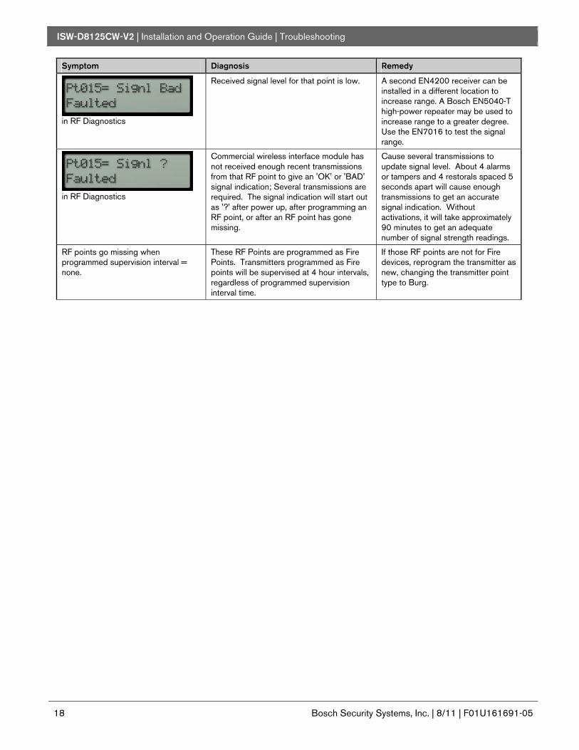
Symptom Diagnosis Remedy
in RF Diagnostics
Received signal level for that point is low. A second EN4200 receiver can be installed in a different location to increase range. A Bosch EN5040-T high-power repeater may be used to increase range to a greater degree. Use the EN7016 to test the signal range.
in RF Diagnostics
Commercial wireless interface module has not received enough recent transmissions from that RF point to give an 'OK' or 'BAD' signal indication; Several transmissions are required. The signal indication will start out as '?' after power up, after programming an RF point, or after an RF point has gone missing.
Cause several transmissions to update signal level. About 4 alarms or tampers and 4 restorals spaced 5 seconds apart will cause enough transmissions to get an accurate signal indication. Without activations, it will take approximately 90 minutes to get an adequate number of signal strength readings.
RF points go missing when programmed supervision interval = none.
These RF Points are programmed as Fire Points. Transmitters programmed as Fire points will be supervised at 4 hour intervals, regardless of programmed supervision interval time.
If those RF points are not for Fire devices, reprogram the transmitter as new, changing the transmitter point type to Burg.
ISW-D8125CW-V2 | Installation and Operation Guide | Troubleshooting
.
Bosch Security Systems, Inc. | 8/11 | F01U161691-05 19
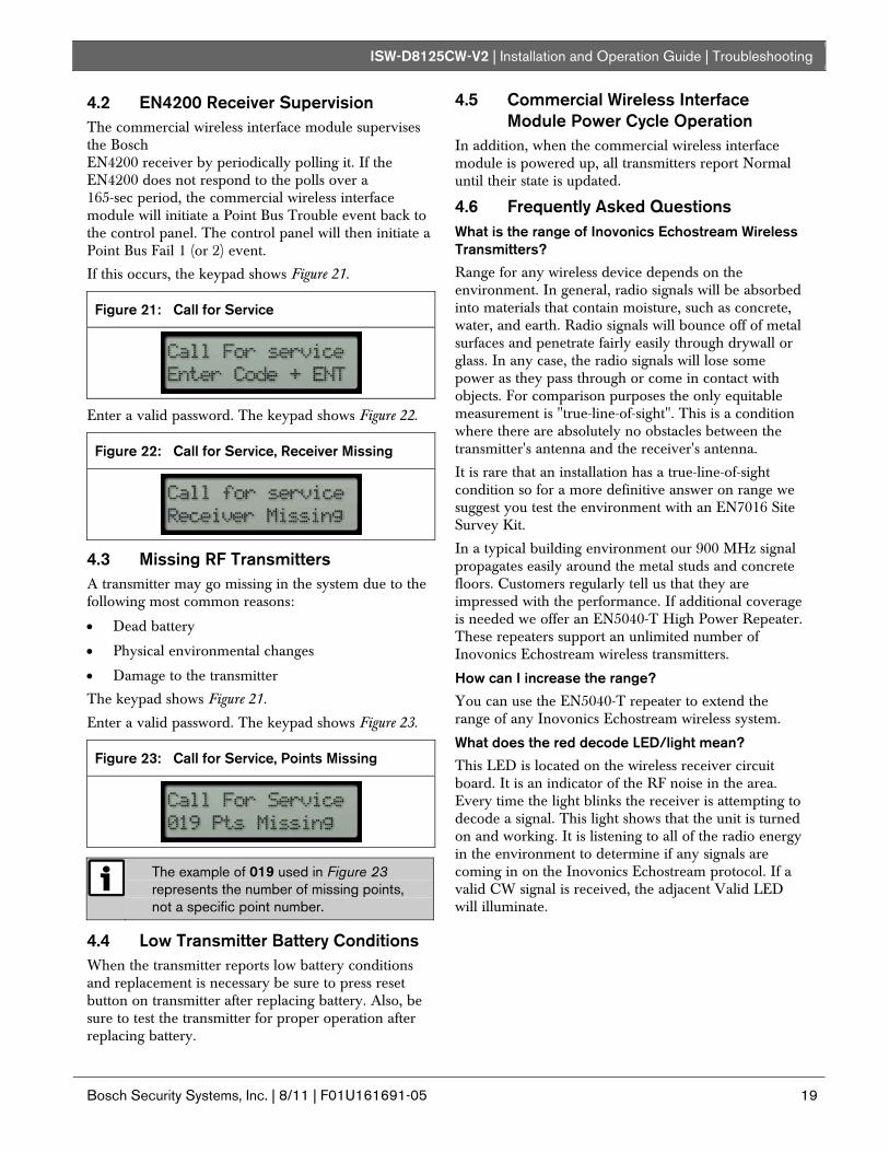
4.2 EN4200 Receiver Supervision The commercial wireless interface module supervises the Bosch EN4200 receiver by periodically polling it. If the EN4200 does not respond to the polls over a 165-sec period, the commercial wireless interface module will initiate a Point Bus Trouble event back to the control panel. The control panel will then initiate a Point Bus Fail 1 (or 2) event.
If this occurs, the keypad shows Figure 21.
Figure 21: Call for Service
Enter a valid password. The keypad shows Figure 22.
Figure 22: Call for Service, Receiver Missing
4.3 Missing RF Transmitters A transmitter may go missing in the system due to the following most common reasons:
• Dead battery
• Physical environmental changes
• Damage to the transmitter
The keypad shows Figure 21.
Enter a valid password. The keypad shows Figure 23.
Figure 23: Call for Service, Points Missing
The example of 019 used in Figure 23 represents the number of missing points, not a specific point number.
4.4 Low Transmitter Battery Conditions When the transmitter reports low battery conditions and replacement is necessary be sure to press reset button on transmitter after replacing battery. Also, be sure to test the transmitter for proper operation after replacing battery.
4.5 Commercial Wireless Interface Module Power Cycle Operation
In addition, when the commercial wireless interface module is powered up, all transmitters report Normal until their state is updated.
4.6 Frequently Asked Questions What is the range of Inovonics Echostream Wireless Transmitters?
Range for any wireless device depends on the environment. In general, radio signals will be absorbed into materials that contain moisture, such as concrete, water, and earth. Radio signals will bounce off of metal surfaces and penetrate fairly easily through drywall or glass. In any case, the radio signals will lose some power as they pass through or come in contact with objects. For comparison purposes the only equitable measurement is "true-line-of-sight". This is a condition where there are absolutely no obstacles between the transmitter's antenna and the receiver's antenna.
It is rare that an installation has a true-line-of-sight condition so for a more definitive answer on range we suggest you test the environment with an EN7016 Site Survey Kit.
In a typical building environment our 900 MHz signal propagates easily around the metal studs and concrete floors. Customers regularly tell us that they are impressed with the performance. If additional coverage is needed we offer an EN5040-T High Power Repeater. These repeaters support an unlimited number of Inovonics Echostream wireless transmitters.
How can I increase the range?
You can use the EN5040-T repeater to extend the range of any Inovonics Echostream wireless system.
What does the red decode LED/light mean?
This LED is located on the wireless receiver circuit board. It is an indicator of the RF noise in the area. Every time the light blinks the receiver is attempting to decode a signal. This light shows that the unit is turned on and working. It is listening to all of the radio energy in the environment to determine if any signals are coming in on the Inovonics Echostream protocol. If a valid CW signal is received, the adjacent Valid LED will illuminate.
ISW-D8125CW-V2 | Installation and Operation Guide | Troubleshooting
20 Bosch Security Systems, Inc. | 8/11 | F01U161691-05
Why can’t I program more than one RF transmitter per point?
Programming more than a single transmitter to a given point number defeats the ability of the Inovonics Echostream system to supervise itself. This is a practice called "stacking points" and is discouraged in practice. Never stack points in a life-safety or security application.
Can I externalize an antenna?
No. The EN5040-T acts as an external antenna.

ISW-D8125CW-V2 | Installation and Operation Guide | Program Record Sheet
.
Bosch Security Systems, Inc. | 8/11 | F01U161691-05 21
5.0 Program Record Sheet
Installer Passcode (123456)
Supervision Interval
Point Table Point # Point
Type Transmitter Type
Loop Type (External Contact) (circle one)
EOL Resistor?
Internal Contacts (Magnetic) Used?
Notes: • Point Text • Location
N/O or N/C Yes / No Yes / No
N/O or N/C Yes / No Yes / No
N/O or N/C Yes / No Yes / No
N/O or N/C Yes / No Yes / No
N/O or N/C Yes / No Yes / No
N/O or N/C Yes / No Yes / No
N/O or N/C Yes / No Yes / No
N/O or N/C Yes / No Yes / No
N/O or N/C Yes / No Yes / No
N/O or N/C Yes / No Yes / No
N/O or N/C Yes / No Yes / No
N/O or N/C Yes / No Yes / No
N/O or N/C Yes / No Yes / No
N/O or N/C Yes / No Yes / No
N/O or N/C Yes / No Yes / No
N/O or N/C Yes / No Yes / No
N/O or N/C Yes / No Yes / No
N/O or N/C Yes / No Yes / No
N/O or N/C Yes / No Yes / No
N/O or N/C Yes / No Yes / No
N/O or N/C Yes / No Yes / No
N/O or N/C Yes / No Yes / No
N/O or N/C Yes / No Yes / No
N/O or N/C Yes / No Yes / No
N/O or N/C Yes / No Yes / No
N/O or N/C Yes / No Yes / No
N/O or N/C Yes / No Yes / No
N/O or N/C Yes / No Yes / No
N/O or N/C Yes / No Yes / No
N/O or N/C Yes / No Yes / No
N/O or N/C Yes / No Yes / No
N/O or N/C Yes / No Yes / No
N/O or N/C Yes / No Yes / No
N/O or N/C Yes / No Yes / No
N/O or N/C Yes / No Yes / No

ISW-D8125CW-V2 | Installation and Operation Guide | Program Record Sheet
22 Bosch Security Systems, Inc. | 8/11 | F01U161691-05
Point # Point Type
Transmitter Type
Loop Type (External Contact) (circle one)
EOL Resistor?
Internal Contacts (Magnetic) Used?
Notes: • Point Text • Location
N/O or N/C Yes / No Yes / No
N/O or N/C Yes / No Yes / No
N/O or N/C Yes / No Yes / No
N/O or N/C Yes / No Yes / No
N/O or N/C Yes / No Yes / No
N/O or N/C Yes / No Yes / No
N/O or N/C Yes / No Yes / No
N/O or N/C Yes / No Yes / No
N/O or N/C Yes / No Yes / No
N/O or N/C Yes / No Yes / No
N/O or N/C Yes / No Yes / No
N/O or N/C Yes / No Yes / No
N/O or N/C Yes / No Yes / No
N/O or N/C Yes / No Yes / No
N/O or N/C Yes / No Yes / No
N/O or N/C Yes / No Yes / No
N/O or N/C Yes / No Yes / No
N/O or N/C Yes / No Yes / No
N/O or N/C Yes / No Yes / No
N/O or N/C Yes / No Yes / No
N/O or N/C Yes / No Yes / No
N/O or N/C Yes / No Yes / No
N/O or N/C Yes / No Yes / No
N/O or N/C Yes / No Yes / No
N/O or N/C Yes / No Yes / No
N/O or N/C Yes / No Yes / No
N/O or N/C Yes / No Yes / No
N/O or N/C Yes / No Yes / No
N/O or N/C Yes / No Yes / No
N/O or N/C Yes / No Yes / No
N/O or N/C Yes / No Yes / No
N/O or N/C Yes / No Yes / No
N/O or N/C Yes / No Yes / No
N/O or N/C Yes / No Yes / No
N/O or N/C Yes / No Yes / No

ISW-D8125CW-V2 | Installation and Operation Guide | Program Record Sheet
.
Bosch Security Systems, Inc. | 8/11 | F01U161691-05 23
Point # Point Type
Transmitter Type
Loop Type (External Contact) (circle one)
EOL Resistor?
Internal Contacts (Magnetic) Used?
Notes: • Point Text • Location
N/O or N/C Yes / No Yes / No
N/O or N/C Yes / No Yes / No
N/O or N/C Yes / No Yes / No
N/O or N/C Yes / No Yes / No
N/O or N/C Yes / No Yes / No
N/O or N/C Yes / No Yes / No
N/O or N/C Yes / No Yes / No
N/O or N/C Yes / No Yes / No
N/O or N/C Yes / No Yes / No
N/O or N/C Yes / No Yes / No
N/O or N/C Yes / No Yes / No
N/O or N/C Yes / No Yes / No
N/O or N/C Yes / No Yes / No
N/O or N/C Yes / No Yes / No
N/O or N/C Yes / No Yes / No
N/O or N/C Yes / No Yes / No
N/O or N/C Yes / No Yes / No
N/O or N/C Yes / No Yes / No
N/O or N/C Yes / No Yes / No
N/O or N/C Yes / No Yes / No
N/O or N/C Yes / No Yes / No
N/O or N/C Yes / No Yes / No
N/O or N/C Yes / No Yes / No
N/O or N/C Yes / No Yes / No
N/O or N/C Yes / No Yes / No
N/O or N/C Yes / No Yes / No
N/O or N/C Yes / No Yes / No
N/O or N/C Yes / No Yes / No
N/O or N/C Yes / No Yes / No
N/O or N/C Yes / No Yes / No
N/O or N/C Yes / No Yes / No
N/O or N/C Yes / No Yes / No
N/O or N/C Yes / No Yes / No
N/O or N/C Yes / No Yes / No
N/O or N/C Yes / No Yes / No
Bosch Security Systems, Inc. 130 Perinton Parkway Fairport, NY 14450 USA www.boschsecurity.com © Bosch Security Systems, Inc., 2011