f02054253
TRANSCRIPT

International Journal of Engineering Research and Development
e-ISSN : 2278-067X, p-ISSN : 2278-800X, www.ijerd.com Volume 2, Issue 5 (July 2012), PP. 42-53
42
Dyamic analysis of balancing of an automobile engine using
ADAMS
Sai Ram. K Assistant Professor, Mechanical Engg., SRM University, Kattangalattur, Chennai, India
Abstract—This paper explain the primary balancing of single cylinder engine and optimizing the counter balancing
mass to reduce the unbalanced forces coming on the crankshaft. After optimizing, the effect of primary balancing is
validated. After primary balancing, the vibration is measured on the engine at various locations. Balancer shaft is
designed for the unbalanced forces exist after primary balancing. Balancer shaft is introduced into the simulation model
and simulated the running at 6000rpm and unbalanced forces on the crankshaft are measured. The vibration on engine
assembly at previously measured location is measured. The effectiveness of primary balancing and balancer shaft is
validated by comparing the acceleration (m/s2) measured at various locations.
Keywords–– Inertia,mass properties,balancing,ADAMS,CATIA.
I. BALANCING METHODOLOGY The methodology involved the following steps
Building of CAD models of individual components of existing Engine model and checking against the actual model
Converting the CAD model into simulation model (ADAMS)
Building the Mechanism in ADAMS using the various joints
Calculating the theoretical unbalanced force and comparing with the Simulation values
Primary balancing and optimizing the counter mass
Validating the impact of primary balancing by measuring the unbalanced forces coming the crankshaft.
Designing the Balancer shaft to reduce the unbalanced forces after primary balancing.
Introducing the balancer shaft into the simulation model and evaluating the impact by measuring the unbalanced
forces on crankshaft
The overall performance characteristics that is Acceleration is measured on the engine in without balancing, with
primary balancing and with balancer shaft.
A. Building of CAD model of individual components: The various engine components are modeled using the solid modeling techniques (Catia V5). The Engine consists of
Piston, Connecting rod, Crankshaft, piston pin, Cylinder block, Cylinder head and Crankcase. All these parts are modeled and checked the mass properties against the actual model.
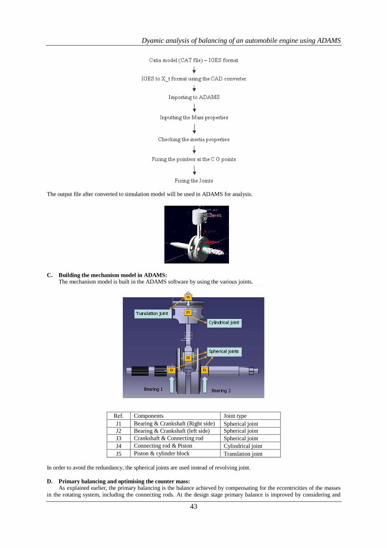
B. Converting CAD model into simulation model: The engine model developed using the solid modeling software need to be converted into simulation model which
involves following steps
Dyamic analysis of balancing of an automobile engine using ADAMS
43
The output file after converted to simulation model will be used in ADAMS for analysis.
C. Building the mechanism model in ADAMS: The mechanism model is built in the ADAMS software by using the various joints.
Ref. Components Joint type
J1 Bearing & Crankshaft (Right side) Spherical joint
J2 Bearing & Crankshaft (left side) Spherical joint
J3 Crankshaft & Connecting rod Spherical joint
J4 Connecting rod & Piston Cylindrical joint
J5 Piston & cylinder block Translation joint
In order to avoid the redundancy, the spherical joints are used instead of revolving joint.
D. Primary balancing and optimising the counter mass: As explained earlier, the primary balancing is the balance achieved by compensating for the eccentricities of the masses
in the rotating system, including the connecting rods. At the design stage primary balance is improved by considering and

Dyamic analysis of balancing of an automobile engine using ADAMS
44
adjusting the eccentricity of each mass along the crankshaft. In theory, any conventional engine design can be balanced perfectly for primary balance. Once the engine is built primary balance is controlled by adding or removing mass to or from the crankshaft, typically at each end, at the required radius and angle, which varies both due to design and manufacturing tolerances.
Mass of the counter mass is equal to mc+c*mp,
Where, mc = mass of the crankpin mp = mass of the connecting rod c = Factor c=0 when no mass of connecting rod is added
c=1 when the full mass of connecting rod is added
The model is simulated the condition of running at 6000rpm and the unbalanced forces coming on the crankshaft
bearing are measured. The forces coming on the crankshaft is measured by varying the C factor in both Y & Z direction.
The unbalanced forces are minimum when C is 0.2 in Y direction and when C is 1.5 in Z direction. The unbalanced forces in Z direction is decrease when C is increasing from 0 to 1.5 and starts increasing but the forces in the Y direction is increasing from 0.2. When C is equal to 0.835, the unbalanced forces on the both Y and Z direction are same. This point taken as the optimized C. At C=0.835,
The mass of the counter mass is 0.2541kg The unbalanced forces on crankshaft is both Y and Z direction are 750N, which needs to balanced by Balancing shaft.
E. Blancer shaft: Many modern engines are fitted with balancer shafts. The principle behind these are originally proposed by Dr.
Lanchester around hundred years ago.A constant rotating force can easily be balanced by another constant rotating force spaced 180° apart. However, it is not as easy as adding another counter weigh to crankshaft, because this force rotates in opposite direction, as we have seen, and therefore can only be balanced by a a counter weight rotating in opposite direction.This is the reason that balance shafts rotate in the opposite direction to the crankshaft.
The crankshaft has a 50%balance factor,and the balance shaft creates further 50% to the balance the reciprocating force when at TDC.At 90° rotation there is no reciprocating force but because the balance shaft rotates in the opposite
Dyamic analysis of balancing of an automobile engine using ADAMS
45
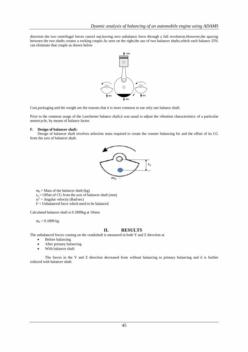
direction the two centrifugal forces cancel out,leaving zero unbalance force through a full revolution.However,the spacing between the two shafts creates a rocking couple.As seen on the right,the use of two balancer shafts,which each balance 25% can eliminate that couple as shown below
Cost,packaging and the weight are the reasons that it is more common to see only one balance shaft. Prior to the common usage of the Lanchester balance shaft,it was usual to adjust the vibration characteristics of a particular motorcycle, by means of balance factor.
F. Design of balancer shaft: Design of balancer shaft involves selection mass required to create the counter balancing for and the offset of its CG
from the axis of balancer shaft.
mb = Mass of the balancer shaft (kg)
rb = Offset of CG from the axis of balancer shaft (mm)
ω2 = Angular velocity (Rad/sec) F = Unbalanced force which need to be balanced
Calculated balancer shaft is 0.1899kg at 10mm
mb = 0.1899 kg
II. RESULTS The unbalanced forces coming on the crankshaft is measured in both Y and Z direction at
Before balancing
After primary balancing
With balancer shaft
The forces in the Y and Z direction decreased from without balancing to primary balancing and it is further
reduced with balancer shaft.

Dyamic analysis of balancing of an automobile engine using ADAMS
46
The forces are same as of single balancer shaft and the additional which caused due to introduction of balancer shaft has got reduced to normal condition. The results are shown in Frequency domain.. Forces in Y direction:
Without Balancing Max peak force = 1652.7N @ 100Hz
With primary balancing Max peak force = 751.8N @100Hz
With Balancer shaft Max peak force = 6.4N @100Hz

Dyamic analysis of balancing of an automobile engine using ADAMS
47
Forces in Z direction:
III. VALIDATION In order to validate the concept, Accelerometers are fixed on the engine assembly at various locations. The main
performance character that is acceleration (m/sec2) is measured in X, Y and Z directions. Location of sensors are shown
below
Without Balancing Max peak force = 3156.9N @ 100Hz
With primary balancing Max peak force = 751.8N @100Hz
Primary component has become almost zero
With Balancer shaft Max peak force = 20N @100Hz

Dyamic analysis of balancing of an automobile engine using ADAMS
48
To simulate the actual running of single cylinder engine, the real condition is simulated by mounting the engine of the engine mounting. The engine assembly is mounted on the vehicle mounts with dampers. The vibration coming on the
engine at different locations are measured. At sensor 1: X direction:
Acceleration at sensor 1 in X direction
-0.15
-0.10
-0.05
0.00
0.05
0.10
0.15
0.20
0.25
0.020 0.022 0.024 0.026 0.028 0.030 0.032 0.034 0.036 0.038 0.040
Time (sec)
Ac
ce
lera
tio
n (
m/s
2)
Without balancing Primary Balancing Balancer shaft
No Balancing Primary Balancing
Balancer shafts
Maximum Acceleration (m/s2) 0.1724 0.0804 0.0578
Minimum Acceleration (m/s2) -0.0927 -0.0678 -0.0642
3
1
2
Dyamic analysis of balancing of an automobile engine using ADAMS
49
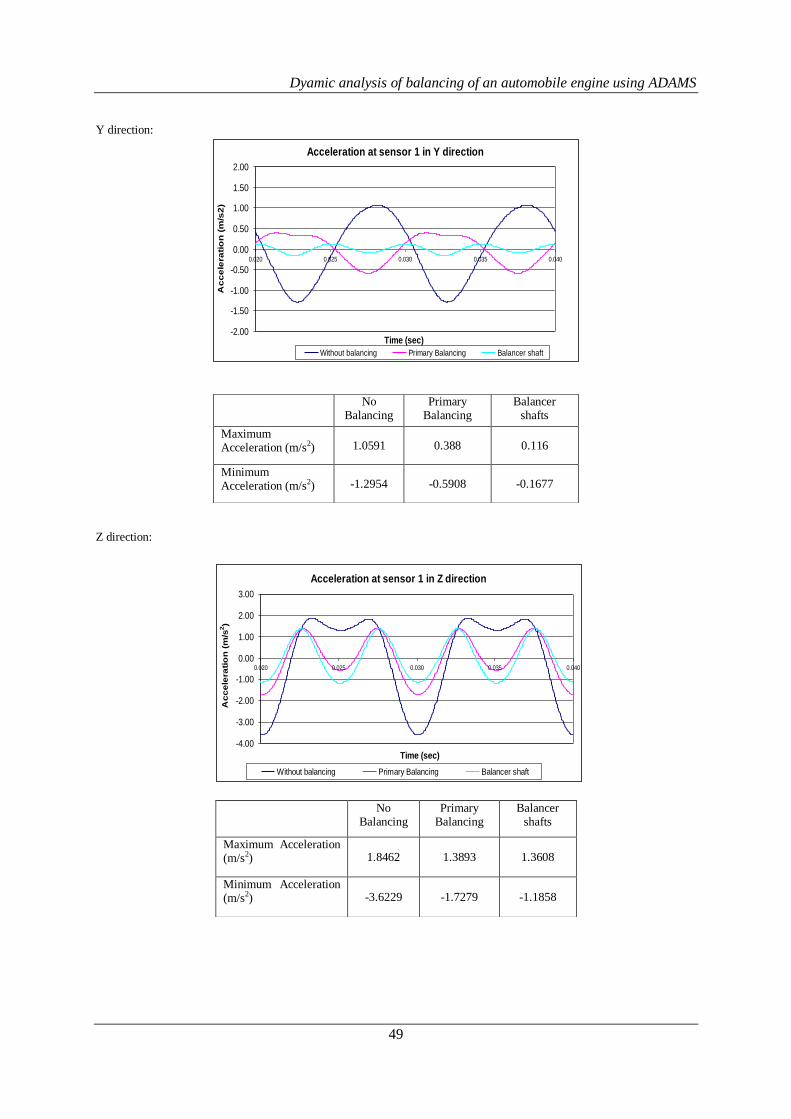
Y direction:
Acceleration at sensor 1 in Y direction
-2.00
-1.50
-1.00
-0.50
0.00
0.50
1.00
1.50
2.00
0.020 0.025 0.030 0.035 0.040
Time (sec)
Ac
ce
lera
tio
n (
m/s
2)
Without balancing Primary Balancing Balancer shaft
Z direction:
No Balancing
Primary Balancing
Balancer shafts
Maximum Acceleration (m/s2) 1.0591 0.388 0.116
Minimum Acceleration (m/s2) -1.2954 -0.5908 -0.1677
No Balancing
Primary Balancing
Balancer shafts
Maximum Acceleration (m/s2) 1.8462 1.3893 1.3608
Minimum Acceleration (m/s2) -3.6229 -1.7279 -1.1858
Acceleration at sensor 1 in Z direction
-4.00
-3.00
-2.00
-1.00
0.00
1.00
2.00
3.00
0.020 0.025 0.030 0.035 0.040
Time (sec)
Ac
ce
lera
tio
n (
m/s
2)
Without balancing Primary Balancing Balancer shaft
Dyamic analysis of balancing of an automobile engine using ADAMS
50
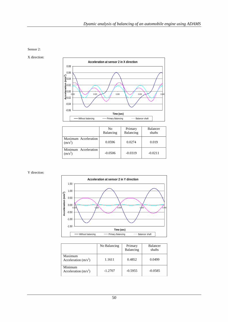
Sensor 2: X direction:
No Balancing
Primary Balancing
Balancer shafts
Maximum Acceleration (m/s2) 0.0596 0.0274 0.019
Minimum Acceleration (m/s2) -0.0506 -0.0319 -0.0211
Y direction:
Acceleration at sensor 2 in Y direction
-1.50
-1.00
-0.50
0.00
0.50
1.00
1.50
0.020 0.025 0.030 0.035 0.040
Time (sec)
Ac
ce
lera
tio
n (
m/s
2)
Without balancing Primary Balancing Balancer shaft
No Balancing Primary Balancing
Balancer shafts
Maximum Acceleration (m/s2) 1.1611 0.4852 0.0499
Minimum Acceleration (m/s2) -1.2707 -0.5955 -0.0585
Acceleration at sensor 2 in X direction
-0.06
-0.04
-0.02
0.00
0.02
0.04
0.06
0.08
0.020 0.025 0.030 0.035 0.040
Time (sec)
Ac
ce
lera
tio
n (
m/s
2)
Without balancing Primary Balancing Balancer shaft
Dyamic analysis of balancing of an automobile engine using ADAMS
51
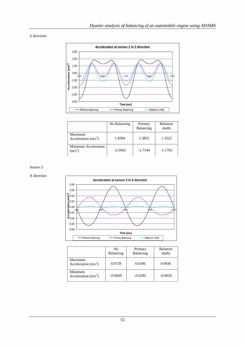
Z direction:
Acceleration at sensor 2 in Z direction
-4.00
-3.00
-2.00
-1.00
0.00
1.00
2.00
3.00
0.020 0.025 0.030 0.035 0.040
Time (sec)
Ac
ce
lera
tio
n (
m/s
2)
Without balancing Primary Balancing Balancer shaft
Sensor 3: X direction
No Balancing Primary
Balancing
Balancer
shafts
Maximum Acceleration (m/s2) 1.8394 1.3852 1.3522
Minimum Acceleration (m/s2) -3.5943 -1.7144 -1.1763
No Balancing
Primary Balancing
Balancer shafts
Maximum Acceleration (m/s2) 0.0728 0.0346 0.0036
Minimum Acceleration (m/s2) -0.0669 -0.0285 -0.0026
Acceleration at sensor 3 in X direction
-0.08
-0.06
-0.04
-0.02
0.00
0.02
0.04
0.06
0.08
0.020 0.025 0.030 0.035 0.040
Time (sec)
Ac
ce
lera
tio
n (
m/s
2)
Without balancing Primary Balancing Balancer shaft

Dyamic analysis of balancing of an automobile engine using ADAMS
52
Y direction:
Z direction:
Acceleration at sensor 3 in Z direction
-4.00
-3.00
-2.00
-1.00
0.00
1.00
2.00
3.00
0.020 0.025 0.030 0.035 0.040
Time (sec)
Ac
ce
lera
tio
n (
m/s
2)
Without Balancing Primary Balancing Balancer shaft
From the above data, it is clear that the vibration levels are decreased from without balancing to primary balancing and its further reduced with balancer shaft.
IV. CONCLUSIONS 1. The unbalanced forces coming on the crankshaft is reduced with primary balancing and its further reduced with the
balancer shaft 2. The torque was increased due to single balancer shaft and the has been controlled to normal condition by
introducing the two balancer shafts of each of half the mass of single balancer shaft placed opposite to each other. 3. The performance parameter vibration (acceleration) coming on the engine is reduced. 4. The packaging of the two balancer shaft and the impact of additional mass need to studied.
No Balancing
Primary Balancing
Balancer shafts
Maximum Acceleration (m/s2) 1.3244 0.6102 0.0168
Minimum Acceleration (m/s2) -1.3412 -0.6269 -0.0287
No Balancing
Primary Balancing
Balancer shaft
Balancer shafts
Maximum Acceleration (mm/s^2)
1.8538 1.4059 1.3600 1.3653
Minimum Acceleration (mm/s^2)
-3.6054 -1.7191 -1.2346 -1.1803
Acceleration at sensor 3 in Y direction
-1.50
-1.00
-0.50
0.00
0.50
1.00
1.50
0.020 0.025 0.030 0.035 0.040
Time (sec)
Ac
ce
lera
tio
n (
m/s
2)
Without Balancing Primary Balancing Balancer shaft
Dyamic analysis of balancing of an automobile engine using ADAMS
53
5. This concept can be implemented for above 150CC motor cycles which prone for more vibration.
REFERENCES [1]. A paper on "A study on the balancing of three-cylinder engine with balancer shaft", Yoon-Ki Lee and Hi-Seak Yoon
[2]. A paper on "Design and optimization of crankshaft torsional vibration damper for a 4-cylinder 4-stroke engine", by Abhijit Londhe ,Vivek H. Yadhav.
[3]. R.L. Norton, “Kinematics and Dynamics of Machinary
[4]. S.S. Rattan, “ Theory of machines”
[5]. S.S Rao, “Mechanical Vibration”
[6]. Fred Karam, Charles Kleismit, “Using Catia”
[7]. J. P. Den Hartog, “Mechanical vibrations”