f2mc-8l - fujitsu global - 2 - read this first this book describes the fujitsu f2 mc-8l starterkit_8...
TRANSCRIPT
page -1-
F2MC-8LMB89620/630/850 Series Evaluation Board
USER MANUAL

page -2-
Read this first
This book describes the Fujitsu F2MC-8L Starterkit_8 and how touse it with the provided tools.
How to use this manual
The goal of this book is to help you learn how to develop your ownsoftware in ANSI-C or Assembler with the Windows-basedenvironment SOFTUNE. This book is divided into 6 parts. Parts 1-3contains hands-on information so that you can start using theevaluation board the same day you receive it. Part 1 is a generaldescription of the board. Part 2 contains installation instructions andpart 3 will guide you through example sessions. Parts 4-6 containdetailed information about the monitor operation, the bios interfaceand the hardware details.
Important notice
This Starterkit contains an evaluation board, documentation andsoftware on a CD-ROM. For last minute changes, please refer to the“Readme.1st”- Document in the Starterkit_8 section on the CD.
Fujitsu reserves the right to make changes to its products or todiscontinue any semiconductor product or service without notice.
Trademarks
DOS, Windows, Windows95 are registered trademarks of Microsoft Corp. PC is a registeredtrademark of IBM.

page -3-
Contents1. Introduction…….…………… ..............................................................................................3
2. General Description ...........................................................................................................32.1. Installation ...............................................................................32.2. Technical Characteristics .........................................................32.3. Evaluation Board Resources....................................................3
3. How to get started, Example Sessions .............................................................................33.1. Examples using Softune: .........................................................33.1.1. The "LED8L" Example .............................................................33.1.2. Debugging examples ...............................................................33.1.3. The "BIOSDEMO" Example.....................................................33.1.4. Program Creation ....................................................................33.1.5. 1 Using the NEWPROJ-example ................................................33.1.6. 2 Configuring Softune .................................................................3
4. Monitor Operation…………................................................................................................34.1. General Operation ...................................................................34.1.1. Command Input .......................................................................34.1.2. Number Formats......................................................................34.2. Monitor Commands..................................................................34.2.1. Setting / Information Commands..............................................34.2.2. HELP, H, ? [Command] ...........................................................34.2.3. HEX, DEC................................................................................34.2.4. TS............................................................................................34.2.5. AS ...........................................................................................34.2.6. ES ...........................................................................................34.2.7. V VALUE ..................................................................................34.2.8. TERM FLAG .............................................................................34.2.9. CLS .........................................................................................34.2.10. STAT .......................................................................................34.2.11. Memory Commands.................................................................34.2.12. D [STARTADDR] [ENDADDR]] ......................................................34.2.13. DW [STARTADDR] [ENDADDR]]...................................................34.2.14. DB [STARTADDR] [ENDADDR]]....................................................34.2.15. SD [NWORD] [L]........................................................................34.2.16. DBR, DRB [FIRSTBANK],[LASTBANK]..........................................34.2.17. S [STARTADDR] [D1 [[D2] ...[D8]]]..............................................34.2.18. F STARTADDR ENDADDR DATA.................................................34.2.19. M STARTADDR ENDADDR TARGADDR .......................................34.2.20. C STARTADDR ENDADDR TARGADDR........................................34.2.21. E [EDITADDR]............................................................................34.2.22. EW [EDITADDR] ........................................................................34.2.23. EB [EDITADDR] .........................................................................34.2.24. A [STARTADDR] .........................................................................34.2.25. R [REGNAME [VALUE]] ...............................................................34.2.26. Program Execution Commands................................................34.2.27. G [STARTADDR] [,STOPADDR] ....................................................34.2.28. CALL TARGADDR [PARAM1 [P2...]] ............................................34.2.29. UC...........................................................................................34.2.30. UR...........................................................................................34.2.31. EXIT ........................................................................................34.2.32. MR, RES, RESET..................................................................34.2.33. Debug Commands ..................................................................34.2.34. B..............................................................................................34.2.35. BC [BNumber] .........................................................................34.2.36. BD [BNUMBER] .........................................................................34.2.37. BE [BNUMBER]..........................................................................34.2.38. T [NINSTR] ................................................................................3
5. Monitor BIOS Interface ......................................................................................................35.1. I/O Function Calls (ASM/C)......................................................3

page -4-
5.1.1. I/O Function Calls Parameter Passing......................................35.1.2. I/O Function Calls Detailed Description....................................35.1.2.1. [00] Poll Character Received ...................................................35.1.2.2. [01] Send Character on RS232 ................................................35.1.2.3. [02] Receive Character on RS232............................................35.1.2.4. [03] Print a String.....................................................................35.1.2.5. [04] Input a String ....................................................................35.1.2.6. [05] Print HexByte....................................................................35.1.2.7. [06] Print HexWord ..................................................................35.1.2.8. [09] Enable/Disable Breakpoints ..............................................35.2. Other BIOS Function Calls (ASM)............................................35.2.1. Print Register Values ...............................................................35.2.2. Monitor Control ........................................................................35.2.3. Monitor Reset ..........................................................................35.2.4. User Program Start ..................................................................35.2.5. SymTab Vector........................................................................3
6. Evaluation Board Hardware................................................................................................. 36.1. Pin Assignment........................................................................36.1.1. MB89630 Configuration..................................................................36.1.2. MB89620 Configuration..................................................................36.1.3. MB89850 Configuration..................................................................3
7. Appendix……………………. ...............................................................................................37.1. Appendix A: Board Schematics................................................37.2. Appendix B: Example Program Listings ...................................37.3. Appendix C: Software Tools.....................................................37.3.1. Windows-tools .........................................................................37.3.2. DOS-tools ................................................................................37.3.3. Download Protocol...................................................................37.4. Appendix D: Monitor Software Notes, Restrictions ...................37.5. Appendix E : List of development tools...........................................3
8. Index………………………….. ...............................................................................................3

page -5-
1. Introduction
The Starterkit_8 is a low-cost, stand-alone application board that makes it easy toevaluate and demonstrate almost all features of FUJITSU's MB89620, MB89630 andMB89850 micro controller series.
Along with the supplied Windows-based development tools, it can be used as asystem for user program developments. The board can be configured to use aMB89T625, MB89T637 or MB89T855 controller by simply exchanging the chip. Bydefault, the board is equipped with an MB89T637.
Monitor software and some on-board peripherals (used to realise an RS232 interfaceto a PC terminal program), support program downloads and provide sophisticateddebug functions such as breakpoint settings, memory dumps, symbol handling andsingle step execution.
A unique feature of this board is a “bank switching mechanism”, which allows theMonitor- EPROM to be disabled and to map a User RAM into the same addressrange. Thus, the user can develop and test program code within the same addressrange as the final user program which would reside in a PROM or mask ROM.
Each memory bank can be activated by a separate Reset button, allowing restart ofeither the Monitor or the User Program, beginning from a real hardware reset.(Note: The Monitor is able to switch the banks automatically by software in order toperform special debug functions.)
Key Features
• Can be configured with MB89T625, MB89T637 or MB89T855• 64 kB RAM• On-board monitor featuring breakpoints, single-stepping, trace etc.• All unused ports available• Integrated Windows-based development environment

page -6-
2. General Description
2.1. Installation
What you’ll need :
ü Host : IBM(-comp) PC with Windows 3.11 or Windows 95 and CD-ROM driveü Power requirements : A power supply, capable of supporting 7-8V DC at about
150 mA, is required. Note that the power connector must be + at the shield and -in the centre
ü RS232 : A ‘Nullmodem’ RS232 cable with a DB9 connector
To install the development environment, insert the provided CD-ROM and click onTOP.PDF from Windows. From the main menu, select “Software Installation”, “8-Bit” and then “Starterkit_8 Installation”. The following procedure will create adirectory named “C:\FETOOL\” and automatically start the individual setup programsof :
§ Softune (8-Bit MCU Version) : Fujitu’s integrated development manager forWindows
§ Language Tools : C-Compiler C96, Assembler ASM96, Linker LINK96, LibrarianLIB96
§ Utilities and examples
To setup the hardware, connect the power supply to the board and check that theUser LEDs light up briefly and that the small red ‘monitor program’ LED (MP)remains on. When pressing the User Reset button, the small green ‘user program’-LED (UP) should be on whilst the reset button is pressed (see figure1).
If these installation checks were successful, the power supply should then beunplugged and the serial connection to a PC via the 9-pin RS232 cable establishedbefore re-connection of the power supply.
Now, the LEDs should still behave in the same manner. If not, it is most likely thatthe DTR signal of the serial connection, which is used as an external monitor resetcontrol line is activated for some reason.
To access the board monitor for testing, any terminal program can be used (e.g. theprovided terminal in the FMG_UTIL directory). The communication parameters are9600 Baud, 8 Databits, no Parity, 2 Stopbits. If a different terminal program isused and the DTR-line can not be set individualy, this effect can be disabled byremoving the “Ext. Reset” jumper, located as in figure 1.

page -7-
Fig. 1 : Evaluation Board Layout
On the terminal, the following message from the evaluation board monitor shouldappear:
********************************************** Monitor for the FFMC8L Series **** MB89xxxx Evaluation Board Vers. x.x **** (C) Fujitsu Mikroelektronik GmbH 199x **********************************************
(C)>
The ´(C)´ status message indicates that the monitor executed a ´cold´ reset afterpower up. Press the monitor reset button to generate a ´warm´ reset, and a ´(W)´message will appear.
The evaluation board is now ready to use.
PowerSupply
User Mon.Reset Reset
RS232Interface
User RAM
Mon.EPROM
L1L2
User LEDs
JP3
JP4
JP7AVxx
JP5(Decode)
A0..15Control
AD0..7Data RAM
Ext. Resetjumper
JP6
JP12MB
89T625or
MB89P637
+
-
UP
MP
MB
89T625
MB
89T637
MB
89T855

page -8-
2.2. Technical Characteristics
Supply Voltage 7V ... 9VRAM Area aro. 62KBROM Area 32KB Monitor ROMMicrocontrollers MB89T625, MB89T637, MB89T855Serial Interface (RS232) Half-Duplex, 9600 Baud, No Parity, 8 Data-bits, 2 Stop-bitsDebug Functions All functions are realised in software including Breakpoints,
Single-Step, Watch-PointsBoard Restrictions Software:
CALLV#7 can not be used because it is needed for thebreakpoint system implementation.
Hardware:Port 0, 1, 2 are used for the external bus system and aretherefore not available as I/O-Ports.
Controller Specific Features MB89T625- 8-bit PWM Timer - 8-bit PWC Timer/Counter- 20-bit TimeBaseTimer - 16-bit Timer/Counter- 2x 8-bit SIO - 8x8 bit A/D- 5 ext. Interrupts - STOP, SLEEP mode- 512 Bytes of internal RAM
MB89T637- 2x 8-bit PWM Timer - 8-bit PWC Timer/Counter- 20-bit TimeBaseTimer - 16-bit Timer/Counter- 8-bit SIO - 8x10 bit A/D- UART - STOP, SLEEP, WATCH mode- 4 Ext. Interrupts - Gear-function- Buzzer output - 32KHz Sub-Clock- 1 kByte of internal RAM
MB89T855- 2x 8-bit PWM Timer - 20-bit TimeBaseTimer- Timer unit (dead timer/ ud counter/ 3ph. motor control)- 8-bit SIO - 8x10 bit A/D- UART - STOP, SLEEP mode- 512 Bytes of internal RAM

page -9-
2.3. Evaluation Board Resources
The evaluation board was designed in order to leave as many micro controllerresources available for user evaluation and applications as possible. All of the IOports (port 3,4,5 and 6) are available to the external world via the on-boardconnectors.The monitor software resides in a bank-switchable EPROM, thus not demanding anyof the 64K external program or data RAM address space.Only a small RAM area is reserved for monitor variables and memory mappedcontrol registers (see memory map). Two of the control registers are linked to theLEDs L1 and L2 and can be used for simple user program indicators. Fig. 2 gives anoverview of the memory structure of the evaluation board.
On Chip IO-Area0000-007F
On Chip RAM0080-027F
External RAM
for User Program
0280
Monitor
8000
User LEDs IO-Addresses
L1 - Addr. 0AE2 Bit 0
L2 - Addr. 0AE3 Bit 0
and User Data
FFFFFFFF
NOTE:
RAM section 0800-0FFFis reserved for the Monitorand memory mapped IO.
Fig. 2 : Memory Structure of the evaluation board

page -10-
3. How to get started, Example Sessions
This chapter will provide some hands-on examples on utilising the available softwaretools for developing software and shows how to download code and data to theboard.
3.1. Examples using Softune:
In the following example sessions, instructions are given on how to use Softune todemonstrate the examples, which will give just a brief impression of the Softunefeatures. To learn more about Softune and its features please refer to thedocumentation on the CD-ROM or to the provided manual.
Please be sure to have the evaluation board powered up and connected to COM1 ofyour PC as described in chapter 2.1. After the software installation, double-click theSoftune-icon (MAN896) to start the program.
3.1.1. The "LED8L" Example
Select “Project/Open Project” and open “LED8L.PRJ” in the “SAMPLE”-directory. Amember list will appear as shown in Fig. 3 which contains all registered files :
Fig.3. : Softune with member-list of the LED8L-project

page -11-
The listed files in the member-list are :
- LED8L.HEX the linker output file this module can be downloaded to the evaluationboard- BEGIN.ASM is a library file containing initialisation functions for C programs- LED8L.C is the source file- MODE_EXT.ASM is a library file containing reset vector and the processor mode byte
NOTE: The "MODE_EXT.ASM" file is used when port 0..2 of the controller are usedas an external bus interface, as on the evaluation board.If projects migrate from the evaluation board onto user-developments, eventuallyusing the "single chip mode" in conjunction with an In-Circuit Emulator or as an OTP,the "MODE_SNG.ASM" must be specified for proper mode byte setting.
To edit one of the files, double-click on the name and the editor will come up with thesource file. As a first example, double-click on “LED8L.C” to see the sourcecode ofthe program.
Using the cursor keys the window can be scrolled and the program can be studied.The main program produces different patterns on the user LEDs, calling a time delaysubroutine after each setting. Close the edit window again, before proceeding.
To compile, assemble and link the project files to an executable program file that canoperate properly on the evaluation board, use the Build-button. (Note that there aretwo other functions available : Make creates the load module by compiling,assembling and linking only updated files and Compile affects individual C-files inthe developing process). With these mouse-driven functions, the software designercan concentrate on coding and debugging programs with improved quality andefficiency, but with no knowledge of how to start and configure a compiler or linker !
When the compilation process is completed, a result window appears showing anyerrors and warnings. This example should compile without problems and completeassembling and linking without any errors. In case of errors, a double-click onto theerror message activates the error-jump-facility and locates the appropriate line in thesource file (try it by generating a simple syntax-error …!).
After linking, an executable program file (LED8L.HEX) is available. This program canbe downloaded to the starterkit. To do so, open the Utility-menu and select“LoadProgram”. You should see a progress-counter while the program is loadingand a “RUN”-button will appear once the program is ready to execute. Afterexecuting the program this way, you finally should see the two LEDs flashing on theboard…

page -12-
3.1.2. Debugging examples
For simplified debugging, an additional symbol file can be generated. The Utiliy-item“LoadSymbols” will generate and download symbol information to the board, whichcan be utilised by the board monitor. After loading symbol information, the monitorcan access the table via a pointer which is included in the information.
After successfully downloading program and symbol information, select the“Terminal” from the Utility-menu. A simple terminal will be called to access themonitor. (Any other terminal-program can be used instead)
When pressing RETURN, the monitor prompt ´>´should appear, or when pressingthe monitor reset button, the initial message from the monitor should appear.
To see if the example program still works, use the G command. (Type G andRETURN)Now the example program is executed on the evaluation board, thus ending thecontrol via the Terminal. The LEDs should start flashing now.
A Monitor Reset must be issued, for example by pressing the monitor reset button, toenable communication with the evaluation board monitor again.
In the following description, some of the monitor-debug functions aredemonstrated:
Use the TS (type symbol) command to list the available symbol information. Thiswill give an overview of most interesting program labels, like _main, _wait etc.
Enter the T command to activate the trace mode. A program label ´===start===´ andsome register information is displayed and the instruction at the program counteraddress is disassembled. This ´start´ location is the reset entry point of the exampleprogram. The code is that of the BEGIN.ASM source code module which containsthe C-program initialisation procedures.
Some instructions may be traced by pressing RETURN.
The monitor will disassemble the actual instruction and wait for a key entry ('SPACE'or 'RETURN') to execute the instruction and to continue with the following one. Onceyou step into the “call _wait” instruction , it will take a long time to finish it.
To avoid to single step time consuming subroutines, you can enter the 'C' key atlocations where such subroutines are called to execute them in real time.
So if the Delay Subroutine was already entered, it might be necessary to reset thePC register as in the beginning and start again.
Press the ESC key to quit the trace mode. Then enter the go,break command
G, _main

page -13-
to complete execution of the initialisation procedures.Program execution will stop at the beginning of the main program.Now, trace again the next 9 instructions to see how the user LEDs are switched.
Finally, set a break point at the wait() subroutine by entering the
B 0 _wait
command.
Now, the example program can be reset by entering the user reset command UR.The program execution will always stop at the wait() subroutine entry.Enter the G command several times to continue program execution and to observethe different user LED states.
Apart from the “GO” (g) command, there are many ways to start a program:
a) Press the UserReset Button → User Program activated (until Monitor Reset)
b) Use the monitor UR command to start the UserProgram at its Reset Entry e.g. UR → User Program activated (until Monitor Reset)
c) Use the monitor GO command to start UserProgram at a specific location (in this example the Reset Entry point (main program loop)). e.g. G 8000 → User Program activated (until Monitor Reset) or G start or G (starts at actual PC location which is also 8000 after a reset)
To demonstrate the Breakpoint with the OccurCounter function, try
B 0 _wait 4
This will execute the main loop 4 times. The example program will stop at the 5thtime the breakpoint is hit.
To demonstrate the Breakpoint/Snapshot function, use
B 0 _wait S
This will effectively just set a snapshot point and the example program will run untilthe monitor reset is pressed. Each time the Snapshot location is executed, themonitor will dump the CPU registers.
These were some basic steps in evaluation board operation and program debug. Tolearn about all possible features please refer to the detailed command description inchapter 5.

page -14-
3.1.3. The "BIOSDEMO" Example
The BIOSDEMO.C example program shows how to utilise I/O functions provided bythe monitor software for user program purposes.To get access to these functions, the EVABIOS.H header file is included and theEVABIOS.ASM library file is linked to the program.
The example program is self explanatory and can be compiled and tested asdescribed in the previous example. Use a terminal to execute the program then youwill see this simple dialog :
>g
***************************************** Demonstration of BIOS Functions *****************************************'puts'-function : This is an output string
'gets'-function : Please enter your name : Master of the universe
Thank you, Master of the universe
'getch'-function : Press any key !
You pressed x
'putch'-function : M a s t e r o f t h e u n i v e r s e
The byte-check sum is : 53 The word-check sum is : 0853
That all folks ! Press any key for Monitor Reset
page -15-
3.1.4. Program Creation
3.1.5.1 Using the NEWPROJ-example
The easiest way to develop software for the evaluation board is to modify theprovided “newproj”-project. This is an already configured example for a MB89T637-equipped evaluation board which can be used to start developing without anymodifications in Softune. It has the following registered files :
• INIT.ASM : An initialization file dedicated for developing software in C for theevaluation board
• NEWPROJ.C : A C-file with all nessesary definitions, but with an empty “main”-routine
• MB89630.ASM : The library file for all IO-definitions (includefile is “MB89630.H”)• INT89630.ASM : The library file for all Interrupt-vectors (includefile is
“INT89630.H”)• MODE_EXT.ASM : The reset-vector / mode-byte library file suitable for the
evaluation board
This means, all IO-registers (e.g. PDR3=0xFF) can be accessed in C and theinterrupt service routines are already defined, but left empty in the C-source. Theinstalled memory-map can also be used for the two other controllers.
3.1.6.2 Configuring Softune
To create completely new software, select “New Project” from the Project menu.Simply specify a name and select the microcontroller family you want to develop theprogram for. After that a new project-directory and –file (.PRJ) will be generated anda new member-list appears.
NOTE: At startup, Softune reads the initial file “man898.ini”. This file containsinformation about directories, projects, utilities etc. Softune reverts to the previoususage conditions by reading this file. Edit this file only offline ! Most of the storedinformation can be changed menu-driven from Softune. Refer to the manuals orpress F1 for help whenever you need it.

page -16-
Fig. 5 : Configurating a Softune-project
To add source and library files to the member-list, type a new file name or select anexisting file – then press ADD and OK to close the dialog. Source file types ( .C.ASM) will be recognized automatically. NOTE : The INIT.ASM-file should be thefirst registered file in the member list
Always specify the memory map for a new project. This information is needed for thelinker to generate absolute code that is executable on your target system. To specifythe memory setup, select “Edit Memory Map” from the Project menu. Insert RAMand ROM size, the number of register banks used and all segment locations asshown below.
Fig. 6 : Configurating the memory map in Softune

page -17-
The table below gives an overview of a typical memory-map used for the board :
Address space Memory area Segment name8000 – FFFF External RAM for Code,
Constant Data etc.CSEG,CCONST,DCONST,DIRCONST
0280 - 7FFF External RAM for Monitor (not used by default)0108 – 027F Internal RAM: Variables (Data)
and StackSSEG (Stacktop=27F),DINIT, DVAR
0100 – 0107 Registerbank #0 (always at 100)0080 – 00FF Internal RAM: fast access DIRINIT, DIRVAR0000 – 007F IO-Area (always at 0)
When writing programs which access these registers, dedicated header and libraryfiles which specify the processor specific control registers should be used.
For example for an MB89620 evaluation board, the linker file for all IO-definitions
C:\FETOOL\8L\LIBRARY\MB89620.ASM
should be used and has to registered in the member list. In the source-code the line
#include <MB89620.h>
should be inserted to declare the functions. Default path names can be changed in“Set Environment Variables” from the Option menu.
Further information regarding the C-compiler, Assembler and Linker can be found inthe online-manuals or the full documentation which can be ordered separately.
NOTE : All language tools (C-Compiler, Assembler, Linker etc.) are DOS-programs.Therefore implementation of Fujitsu language tools in any individual developmentenvironment or the use of batch-files is possible.

page -18-
4. Monitor Operation
4.1. General Operation
This chapter describes the monitor of the board in detail. The monitor can beoperated via any PC terminal, like the included terminal in the FMG_UTIL-directory.The communication parameters are 9600 baud, 8 bit, no parity, 2 stop bits. Ifpossible, ANSI terminal emulation should be activated. After pressing the MonitorReset Button, the Monitor LED on the evaluation board should be active and amessage from the Monitor should appear on the terminal. The monitor is then readyfor command input.
4.1.1. Command Input
Commands must only be entered if the monitor has posted the command prompt
> .
This is important since the RS232 interface is realised by a software pollingprocedure and characters will get lost if the monitor is busy while characters aretyped in.
A command is input by typing the command word plus appropriate parameters andthen pressing RETURN to terminate input and execute the command.
The monitor provides the following edit functions:
• Mis-typed characters can be erased by using the BACKSPACE key.• Pressing the TAB key, will automatically re-type the previous command.• A complete command line can be skipped by pressing the ESC key.
page -19-
4.1.2. Number Formats
Most commands need parameters, usually numbers. The monitor uses the followingconvention regarding the representation or base:
By default, all numeric inputs are regarded as HEX numbers
• Characters '0..9' and 'A..F' or 'a..f'.
• Decimal numbers can be input by prefixing the numberwith the two characters "D ' " or with the character "!".
Example
e.g. D ' 100 or !100 equate to 100 dec.
• The default input format can be changed to DEC by a monitor command.
• Characters '0..9'.In this case, hex numbers can be input by the two prefix characters "H ' " or withthe single character "$" or with an appended "H".
Example
e.g. H ' F00 or $F00 or F00H equate to 0F00 hex.
NOTE: Numbers output by the monitor are always in HEX format !
The monitor features the capability of accepting symbol names for parameter inputs.To use this option, Symbol Information must be available (see TS command).
page -20-
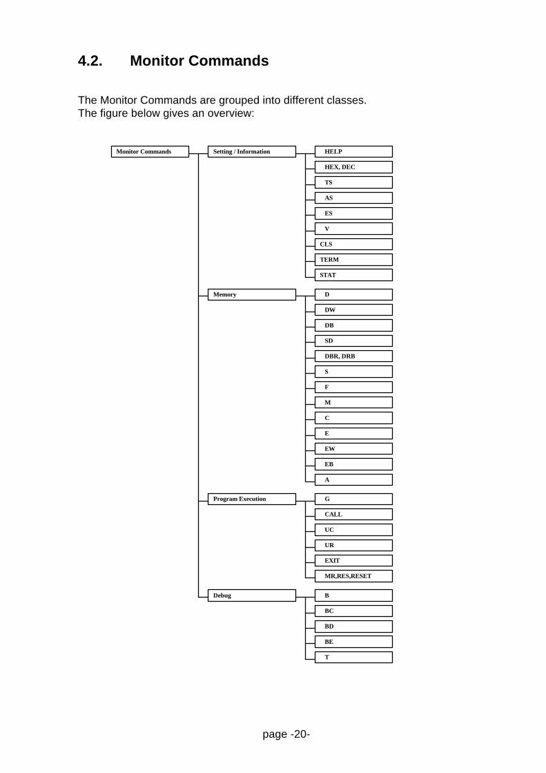
4.2. Monitor Commands
The Monitor Commands are grouped into different classes.The figure below gives an overview:
Setting / InformationMonitor Commands HELP
STAT
HEX, DEC
TERM
CLS
Memory
TS
AS
ES
V
D
DW
DB
SD
DBR, DRB
S
F
M
C
E
EW
EB
A
GProgram Execution
CALL
UC
UR
EXIT
MR,RES,RESET
BDebug
BC
BD
BE
T

page -21-
4.2.1. Setting / Information Commands
4.2.2. HELP, H, ? [Command]
Print Help Text
The HELP command prints a short overview of the most important monitorcommands.Shortcuts for this are H and ?. If a command is named, specific help is displayed.
4.2.3. HEX, DEC
Specify Default Input Mode
The HEX or DEC command specifies the default format of numbers required forcommand parameters.
4.2.4. TS
Type Symbol Information
This command will type all symbol names and values, if available.The monitor can accept symbol names as command parameters and will displaysymbol names within in the 'L' and 'T' commands if symbol information is available.Symbol information can be included within the User Program (see exampleprograms) or can be separately downloaded into any free RAM area.
4.2.5. AS
Activate Symbols
In the case where the symbol table has not been activated during programdownload, the AS command can be used to scan the memory for a symbol table andinitialise the symbol management.

page -22-
4.2.6. ES
Erase Symbol Table
The Erase Symbols command will delete the symbol and thus disable the symbolicdebug features.
4.2.7. V VALUE
Print Value in various number formats
The Value command can be used to print a different representation of a value.For example if a hex number is specified as the Value operand, the decimal andbinary equivalents are printed.
4.2.8. TERM FLAG
Specify ANSI emulation features
Some terminal programs are able to decode special escape sequences whichchange the actual colour or result in other screen manipulations. The monitor can beconfigured to generate such sequences to print its output messages using differentcolours and to clear the terminal window on certain points. To activate thesefeatures, the TERM command is used to set related flags:
Flag values: 0 use no escape codes1 utilise Clear Screen code2 utilise ANSI colour codes3 utilise Clear Screen & ANSI codes
Note that these terminal emulation functions are not supported by ProMan !
4.2.9. CLS
Clear Screen
The CLS command will print the ´Clear Screen´ escape sequence if enabled (seeTERM).
page -23-
4.2.10. STAT
Print Information
The STAT command can be used to print information on the monitor status.For example if the monitor is in HEX or DEC input mode and additional informationabout the monitor BIOS version.
4.2.11. Memory Commands
4.2.12. D [STARTADDR] [ENDADDR]]
Dump Memory Area
The Dump command displays the memory contents of the specified address range.If no EndAddress is specified, a memory area of 64 bytes is displayed.If no StartAddress is specified the dump is continued at the following location of aprevious dump.
4.2.13. DW [STARTADDR] [ENDADDR]]
Dump Memory Area in Word format
The Dump Words command dumps memory contents in 16 bit word format.(See also 'D' command).
4.2.14. DB [STARTADDR] [ENDADDR]]
Dump Memory Area in Bit format
The Dump Words command dumps memory contents in single bit format.(See also 'D' command).
4.2.15. SD [NWORD] [L]
Stack Dump
The Stack Dump command dumps the actual stack area contents. A number ofWords can be specified. Using the 'L' flag, the monitor evaluates each stack valueand checks if it might be a return address. In that case the available symbol nearestto that address is printed.

page -24-
4.2.16. DBR, DRB [FIRSTBANK],[LASTBANK]
Dump Register Bank
The DBR or DRB command can be used to dump the register bank memory area.Without parameters, the current active register bank is printed.A specific bank (0..31) or range can be specified by operands.
4.2.17. S [STARTADDR] [D1 [[D2] ...[D8]]]
Search for a specific byte pattern
The Search command will search for a specific data pattern in memory beginning atthe StartAddress. The data pattern is specified by up to 8 byte values.Note: The StartAddress must by specified using 4 characters (e.g. '00F0'), otherwisethe first parameter is interpreted as a data pattern and a default address is used.If a matching data pattern is found, the address is displayed. In this case, if theSearch command is used again without parameters, the search will be continuedafter the previous matching location.
4.2.18. F STARTADDR ENDADDR DATA
Fill Memory Area
The Fill command fills a specified memory area with the specified Data value.
4.2.19. M STARTADDR ENDADDR TARGADDR
Move Memory Area
The Move command moves the contents of a specified memory area to a differentlocation beginning at the TargetAddress.The original memory area remains unchanged unless source and target areaoverlap.

page -25-
4.2.20. C STARTADDR ENDADDR TARGADDR
Compare Memory Areas
The Compare command compares one memory area specified by StartAddress andEndAddress with a second memory area beginning at the TargetAddress. Memorylocations with different contents are displayed.
4.2.21. E [EDITADDR]
Edit Byte Data in Memory
The Edit command allows the modification of single memory locations, beginning atthe specified EditAddress. (If not specified, a previously specified address is used.)The monitor will display the actual address and the contents. The user can enternew data values or simply press RETURN to move to the next address location. Toquit the edit procedure press the ESC key or enter /↵.
4.2.22. EW [EDITADDR]
Edit Word Data in Memory
The Edit Word command allows modification of 16 bit word memory locations.Otherwise, it operates in the same manner as the E command.
4.2.23. EB [EDITADDR]
Edit Data in Memory Bit by Bit
The Edit Bit command allows modification of single memory bits. This commandworks in a similar manner to the E command.
4.2.24. A [STARTADDR]
On-line Assembler
The A command enters the on-line assembler mode. Instructions can be enteredusing the F2MC8L/8LC assembly language.To escape the on-line assembler simple press return on an empty line or press theESC key.

page -26-
4.2.25. R [REGNAME [VALUE]]
Show Registers, Change Register Contents
The register command, without parameters displays the CPU register contents (A, T,IX, EP, PS, SP, PC ) and the current register bank registers R0..R7)If a RegisterName and Value is specified, the register will be updated.
If the Value is not specified, the monitor will enter an 'edit register mode'. It will printthe current value and prompt for a new value. The user can either specify a newvalue or simply press RETURN to keep the actual value. Then the next CPU registerand its content is displayed and can be changed. To exit this edit mode, press theESC key or type /↵.
• The register named 'CY' -which is not an actual processor register- can bechanged in this mode. The 'CY' register is the monitor cycle counter used withinthe trace command.
4.2.26. Program Execution Commands
4.2.27. G [STARTADDR] [,STOPADDR]
Go to start User Program
The Go command is used to switch control from the Monitor to the UserProgram.The UserProgram execution is started with the current CPU register contents (see'R' command) at the location specified by the PC register. If a StartAddress isspecified, the PC register is set to this value.
A StopAddress can be specified which sets a temporary breakpoint. If theUserProgram stops at any breakpoint before the StopAddress is reached thistemporary breakpoint is automatically removed.
Examples:
e.g. G ,mainorG reset,main
4.2.28. CALL TARGADDR [PARAM1 [P2...]]
CALL Subroutine
The CALL subroutine command allows the calling of a User Program or Procedurestarting at the Specified TargetAddress.

page -27-
Parameters passed to the subroutine can be specified optionally and will be passedto the procedure on the stack (as done by the C-compiler function calls).When returning from the procedure a message and the return value in register EP isautomatically displayed.
4.2.29. UC
User Program Call
The User Program Call works in a similar way to the 'CALL' command with thedifference that no target address is specified in the command line.To use this function, an appropriate JMP instruction must be entered into a specificBIOS table location (see BIOS Interface) when downloading the program.
4.2.30. UR
User Program Reset
The monitor will activate the user program RAM bank and initiate a hardware reset,so the user program will start, beginning its reset vector.
Note: This command is equivalent to pressing the User Reset button.
4.2.31. EXIT
Exit Monitor Shell
If the monitor is called by a User Program via the BIOS interface as a shell program,program control can be returned to the user program using the EXIT command.
4.2.32. MR, RES, RESET
Monitor Reset
This command is equivalent to pressing the Monitor Reset button.
page -28-
4.2.33. Debug Commands
4.2.34. B
B [BNUMBER BREAKADDR [OCCCOUNT] ['S'] ['W' WADDR WCNT]
Set Breakpoint/Snapshot/Watch-area
If no parameters are specified, the Breakpoint command will display the currentbreakpoints list. If a BreakpointNumber and a BreakpointAddress are specified, abreakpoint is set at the specified program location. The BreakpointNumber (0..9) ismaintained as a reference. It will be displayed when using the 'L' command and mustalso be specified to clear a specific breakpoint.
When the user program is executed, it will stop when a breakpoint is reached andBreakpoint Information (CPU registers, Breakpoint location) will be displayed.
Specifying an OccurCount value allows the processor to 'run over the breakpoint'OccurCount-times before the breakpoint is activated.
Additionally, by setting the watch memory area flag ´W´, the breakpoint informationcan be extended to add a dump of a specified memory space.´W´ must be followed by a start address ´wAddr´ and byte count ´wCnt´.
Specifying a Snapshot flag 'S' converts the breakpoint into a 'Snapshot-point'. Thatis, the Breakpoint Information is displayed whenever the snapshot-point is reachedbut program execution continues.Using the OccurCounter in this case, program execution will stop when it reacheszero.
NOTES:- If a previously used BreakpointNumber is specified again, the previous breakpoint
is overwritten.
- Do not specify the same BreakpointAddress more than once !
- The monitor stores its breakpoint information in a Monitor RAM section which is notinitialised (cleared) after a Monitor Reset. A check sum mechanism makes sure theinformation is valid. Thus, if an 'out of control' user program has to be stopped byReset, the specified breakpoints remain valid unless the user program hasdestroyed its own code or the Monitor RAM.

page -29-
4.2.35. BC [BNumber]
Clear Breakpoint
If no BreakpointNumber is specified, this command will clear all breakpoints.
4.2.36. BD [BNUMBER]
Disable Breakpoint
If no BreakpointNumber is specified, this command will disable all breakpoints.
4.2.37. BE [BNUMBER]
Enable Breakpoints
If no BreakpointNumber is specified, this command will enable all breakpoints.
4.2.38. T [NINSTR]
Trace Instruction
The Trace command can be used to single step a user program, beginning at the PCregister address. 'nInstr' specifies the number of instructions which shall beexecuted automatically. If not specified, the trace will start in interactive mode.
Note: The Program Address Counter can be set to a specific address using the "RPC val" command prior to using the trace command.
The interactive operation works according to the following loop.
LOOP• the monitor displays the actual register values and prints the disassembled
instruction• then the User is prompted to press the 'SPACE', 'RETURN', 'C' or 'R' key to
execute the instruction or press any other key to abort the trace operation• continue loop if not aborted
page -30-
This way, the register values before and after executing an instruction are alwaysdisplayed.
Special key functions:•• 'SPACE' or 'RETURN' will execute one instructions at a time.• If 'C' is used at a CALL subroutine instruction, the subroutine is executed without
tracing.• If 'R' is used at a Branch instruction, a taken branch will not be traced.
This means, if a branch is taken, the program will continue to execute untilreaching the instruction following the branch (branch not taken).This has applications in skipping long polling or timing loops.
Important:The monitor uses the CALLV #7 instruction and the corresponding vector in theUserRAM to realise the Breakpoint and Trace operation. Thus, this instruction mustnot be invoked by the user program.

page -31-
5. Monitor BIOS Interface
The monitor incorporates a software interface for user programs providing functionsfor basic terminal input / output operations.
When developing application or user programs, it is common practice to includesome additional code which prints out debug or other status information during thefirst trial runs, to verify the proper operation of certain procedures.To relieve the user from coding appropriate input/output procedures (which will beneeded just for debug purpose and not in the final program), the BIOS interface canbe used.
The following is a detailed description on the available BIOS functions.Examples can be found within the example programs discussed in chapter 5.
The BIOS interface is realised as a call entry table located in a reserved area ofRAM (below the bankswitch-able ROM / RAM) and has the following structure:
In the following table, entries are termed `function vectors`.
Monitor Reset
Table Header at 0800h
"BIOS Vxx"
Monitor Control
00
10
The first 8 Bytes contain a signature
Call a Monitor Shell
Monitor (Software) Reset
Table Offset
I/O Function Calls (ASM) 08
I/O Function Calls (C) 0C
1C
Call the following location for :
BIOS Functions (Parameters in Registers)
BIOS Functions (Parameters on Stack)
Reserved
14
18
Print Register Values
(Monitor internal use for Trace & Break)
Print CPU Registers
This entry can be set by the user program
This entry can be set by the user program
20
24
User Program Start
Pointer to Symbol Table
The start address of the table is at location 0800h. The table header should bechecked before calling a table entry.
page -32-
5.1. I/O Function Calls (ASM/C)
5.1.1. I/O Function Calls Parameter Passing
The most commonly used function vectors are those for ´I/O Function Calls´.Specifying a function code byte and additional parameters will execute a specific I/Ofunction.
Two different table entries are available.The (ASM) entry is optimised for assembly language calls, which pass requiredparameters in CPU registers.The (C) entry is optimised for C-program calls, which pass parameters via the stack.
The following convention is used to specify function code and parameter:
a) Function Call (ASM) Register AH : Function code number AL : Byte Parameter
EP : 2nd Parameter (address pointer)e.g. :
MOVW A,#(H'0100 | '*') ; Function Code 01 => AH, '*' => ALCALL H'0808 ; Call BIOS function
b) Function Call (C) 1st word on stack : HiByte Funct.Code, LoByte Param.2nd word on stack : 2nd Parameter (address pointer)
e.g. :
char (*BiosCall)(int,int) = 0x080C;BiosCall( (0x0100 | '*'), NULL);
On return, a 16 bit value is passed back to the calling routine via the EP register.Generally, a negative return value is regarded as an error exit code.Note that as with C-Subroutines, only the registers IX, R2..R7 will be saved, all otherregisters can have different values.
NOTE: An include file with macro definitions for assembly programs (EBIOS.INC), ora header and library file for C programs (EVABIOS.H, EVABIOS.C) contain thedeclarations which simplify the usage of I/O functions. These files are also used inthe examples described in chapter 5.

page -33-
The following table lists the functions provided via I/O Function Calls:
Function FCode.
Byte Param. 2ndParameter
ReturnValue
Poll Char Received* 00 1:Rec, 0:NoSend Char on RS232 01 Output Char - -Receive Char 02 - - Input CharPrint a String 03 - Adr Pointer -Input a String 04 b6..0=SLen
b7=CrLfAdr Pointer Inp.Termn.
CharPrint a HexByte 05 HexByte - -Print a HexWord 06 - HexWord -(reserved) 07(reserved) 08Enable/Dis. BreakPnt. 09 1:En., 0:Dis. - -
* Restricted Functionality
5.1.2. I/O Function Calls Detailed Description
5.1.2.1. [00] Poll Character Received
This function works in a similar way to computer BIOS functions, in checking whethera key was pressed and whether the character is available in a keyboard buffer ornot. Since the evaluation board uses a polling type of software UART, thefunctionality is restricted:The function will just scan the Rx-receive line for some time and see if a character isdetected. A function call to actually read the character will then wait for the nextreceived character.
5.1.2.2. [01] Send Character on RS232
This function will transmit a single character (byte) on the RS232 transmit line, to bedisplayed on the attached computer terminal.
5.1.2.3. [02] Receive Character on RS232
This function will poll the RS232 receive line until a character is detected and finallyreturn the received character.

page -34-
5.1.2.4. [03] Print a String
This function will transmit a complete string of character via RS232, to allowmessage outputs on the computer terminal. The string termination character is “00h”.
5.1.2.5. [04] Input a String
This function reads a complete string from the computer terminal.The input is terminated when the RETURN or ESC key is pressed, or the max. stringlength is exceeded.
If specified, a CR-LF sequence will be sent to the terminal to position the cursor ontothe next line. The max. string length (bit 0..6) and the CrLf flag (bit 7) are specifiedby the parameter byte.
5.1.2.6. [05] Print HexByte
This function will convert the byte parameter into a 2-digit hex-ascii number andtransmit it to the terminal.
5.1.2.7. [06] Print HexWord
This function will convert the word parameter into a 4-digit hex-ascii number andtransmit it to the terminal.
5.1.2.8. [09] Enable/Disable Breakpoints
Depending on the byte parameter, this function can temporarily disable or re-enableall breakpoints set by the operator.
page -35-
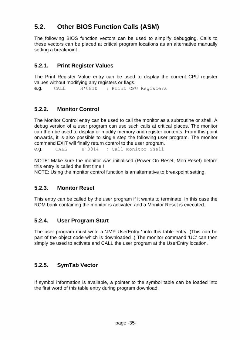
5.2. Other BIOS Function Calls (ASM)
The following BIOS function vectors can be used to simplify debugging. Calls tothese vectors can be placed at critical program locations as an alternative manuallysetting a breakpoint.
5.2.1. Print Register Values
The Print Register Value entry can be used to display the current CPU registervalues without modifying any registers or flags.e.g. CALL H'0810 ; Print CPU Registers
5.2.2. Monitor Control
The Monitor Control entry can be used to call the monitor as a subroutine or shell. Adebug version of a user program can use such calls at critical places. The monitorcan then be used to display or modify memory and register contents. From this pointonwards, it is also possible to single step the following user program. The monitorcommand EXIT will finally return control to the user program.e.g. CALL H'0814 ; Call Monitor Shell
NOTE: Make sure the monitor was initialised (Power On Reset, Mon.Reset) beforethis entry is called the first time !NOTE: Using the monitor control function is an alternative to breakpoint setting.
5.2.3. Monitor Reset
This entry can be called by the user program if it wants to terminate. In this case theROM bank containing the monitor is activated and a Monitor Reset is executed.
5.2.4. User Program Start
The user program must write a 'JMP UserEntry ' into this table entry. (This can bepart of the object code which is downloaded .) The monitor command 'UC' can thensimply be used to activate and CALL the user program at the UserEntry location.
5.2.5. SymTab Vector
If symbol information is available, a pointer to the symbol table can be loaded intothe first word of this table entry during program download.

page -36-
6. Evaluation Board Hardware
The evaluation board provides various IO-signals which can be connected toexternal devices. The controller resource functions are available on the connectorsJP3, JP4, JP7 and JP5.External peripheral devices can be connected via the address/data bus on JP6 andJP12 and the select signal /EIO on JP5. For more information please refer to thefollowing pin assignments and the schematics in appendix A.
6.1. Pin Assignment
The F2MC-8L evaluation board PCB was designed such that it can be used for theMB89620, MB89630 and MB89850 series of Fujitsu’s 8-bit micro-controllers.Thus, the MB89T637 can be simply replaced by a T625 or T855 to derive anevaluation board for the device family. The main differences between the boardversions are different I/O signals on ports 3,4 and 5 and the associated connectors.
6.1.1. MB89630 Configuration
A10 11A12 13A14 15
12 A1114 A1316 A15
BUFC 17HRQ 19
/RD 23
18 /HAC20 RDY
24 ALECLK 21 22 /WR
VCC 25 26 GND
A0 1A2 3A4 5A6 7A8 9
2 A14 A36 A58 A710 A9
97531
531
8
246
10
2468
12
7
1113
9
14
10
P42/UI2VCC
P50/ADSTP52P40/UCK2
P51/BZ
P43/PTO1P41/UO2P53/PTO2
1
7
2
10
P61/AN1VCC
P63/AN3
P67/AN7P65/AN5
GND
P74/ECGND
P72/INT2
/RESP70/INT0/X1A
/SRA
GNDP66/AN6
P60/AN0P62/AN2P64/AN4
AVR
MAP/EAA
-P73/INT3P71/INT1/X0A
/RAM
35
13
911
15
468
121416
/EIO
-
/ROM
GNDP31/UO1P33/SCK1P35/SI1P37/WTO
13579
P30/UCK1P32/UI1P34/SO1P36/PWCVCC
246810
GNDAD1AD3AD5AD7
13579
AD0AD2AD4AD6VCC
246810
MOD1MOD0
VCC
VCC GND
/EADGND
/EAA
GND
AVR
VCC
VCC
GND
GNDAVSS
AVSS
AVCC
AVCC
/MRES
/RES
JP13 JP15
JP16off for
ext. UARTProbe
connector
ext. Resetvia Terminal
JP3
JP4
JP7
JP5
JP12
JP6
JP10
JP1JP2
Fig. 7 : MB89630 Evaluation board connector and jumper assignment

page -37-
6.1.2. MB89620 Configuration
A10 11A12 13A14 15
12 A1114 A1316 A15
BUFC 17HRQ 19
/RD 23
18 /HAC20 RDY
24 ALECLK 21 22 /WR
VCC 25 26 GND
A0 1A2 3A4 5A6 7A8 9
2 A14 A36 A58 A710 A9
97531
531
8
246
10
2468
12
7
1113
9
14
10
P41VCC
P47/SI2P45/SCK2P43
P46/SO2
P40P42P44/BZ
1
7
2
10
P51/AN1VCC
P53/AN3
P57/AN7P55/AN5
GND
P60GND
P62
/RESP64
/SRA
GNDP56/AN6
P50/AN0P52/AN2P54/AN4
AVR
MAP/EAA
-P61P63
/RAM
35
13
911
15
468
121416
/EIO
-
/ROM
GNDP36/WTOP34/ECP32/SO1P30/ADST
13579
P37/PTOP35/PWCP33/SI1P31/SCK1VCC
246810
GNDAD1AD3AD5AD7
13579
AD0AD2AD4AD6VCC
246810
MOD1MOD0
VCC
VCC GND
/EADGND
/EAA
GND
AVR
VCC
VCC
GND
GNDAVSS
AVSS
AVCC
AVCC
/MRES
/RES
JP13 JP15
JP16off for
ext. UARTProbe
connector
ext. Resetvia Terminal
JP3
JP4
JP7
JP5
JP12
JP6
JP10
JP1JP2
Fig. 8 : MB89620 Evaluation board connector and jumper assignment

page -38-
6.1.3. MB89855 Configuration
Fig. 9 : MB89850 Evaluation board connector and jumper assignment
NOTE: The MB89620 and MB89850 series doesn’t have any sub-clock inputs, sothe 32KHz sub-clock crystal which is mounted on the board for the MB89630configuration could be disconnected from P63 and P64 (see schematics) by cuttingthe solder-bridges SB1 and SB2 on the solder side of the PCB (closely located tothe 32 KHz crystal).
Since the crystal connection to the port inputs should not have much influence onthe port functions, we recommend to keep the solder-bridges in for an easy upgradeback to the MB89630 version.
A10 11A12 13A14 15
12 A1114 A1316 A15
BUFC 17HRQ 19
/RD 23
18 /HAC20 RDY
24 ALECLK 21 22 /WR
VCC 25 26 GND
A0 1A2 3A4 5A6 7A8 9
2 A14 A36 A58 A710 A9
97531
531
8
246
10
2468
12
7
1113
9
14
10
P46/ZVCC
P40/RTO0P42/RTO2P44/X
P41/RTO1
P47/TRGP45/YP43/RTO3
1
7
2
10
P51/AN1VCC
P53/AN3
P57/AN7P55/AN5
GND
P64/DTTI
GND
P62/INT2/RES
P60/INT0
/SRA
GNDP56/AN6
P50/AN0P52/AN2P54/AN4
AVR
MAP/EAA
-P63/INT3P61/INT1
/RAM
35
13
911
15
468
121416
/EIO
-
/ROM
GNDP31/SO1P33/SCK2P35/SI2P37/PTO2
13579
P30/SCK1P32/SI1P34/SO2P36/PTO1VCC
246810
GNDAD1AD3AD5AD7
13579
AD0AD2AD4AD6VCC
246810
MOD1MOD0
VCC
VCC GND
/EADGND
/EAA
GND
AVR
VCC
VCC
GND
GNDAVSS
AVSS
AVCC
AVCC
/MRES
/RES
JP13 JP15
JP16off for
ext. UARTProbe
connector
ext. Resetvia Terminal
JP3
JP4
JP7
JP5
JP12
JP6
JP10
JP1JP2
page -39-
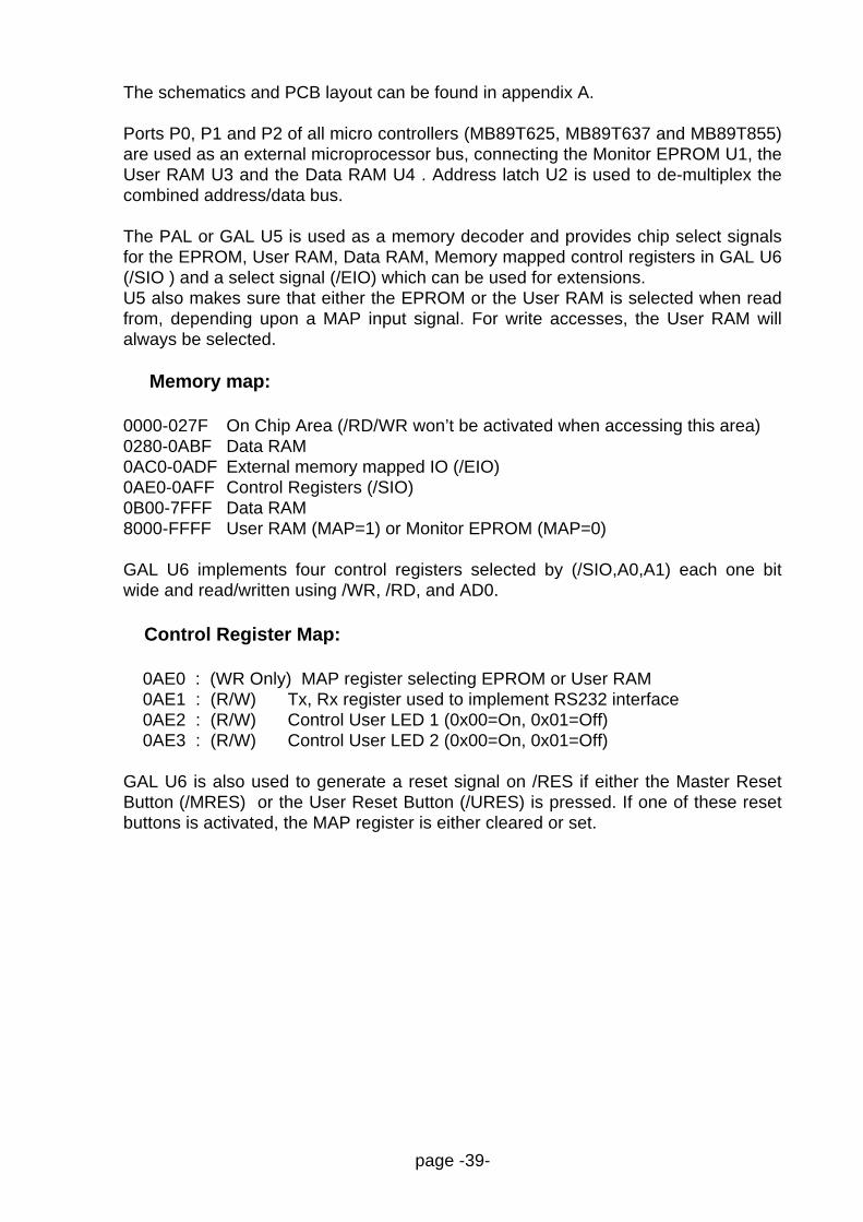
The schematics and PCB layout can be found in appendix A.
Ports P0, P1 and P2 of all micro controllers (MB89T625, MB89T637 and MB89T855)are used as an external microprocessor bus, connecting the Monitor EPROM U1, theUser RAM U3 and the Data RAM U4 . Address latch U2 is used to de-multiplex thecombined address/data bus.
The PAL or GAL U5 is used as a memory decoder and provides chip select signalsfor the EPROM, User RAM, Data RAM, Memory mapped control registers in GAL U6(/SIO ) and a select signal (/EIO) which can be used for extensions.U5 also makes sure that either the EPROM or the User RAM is selected when readfrom, depending upon a MAP input signal. For write accesses, the User RAM willalways be selected.
Memory map:
0000-027F On Chip Area (/RD/WR won’t be activated when accessing this area)0280-0ABF Data RAM0AC0-0ADF External memory mapped IO (/EIO)0AE0-0AFF Control Registers (/SIO)0B00-7FFF Data RAM8000-FFFF User RAM (MAP=1) or Monitor EPROM (MAP=0)
GAL U6 implements four control registers selected by (/SIO,A0,A1) each one bitwide and read/written using /WR, /RD, and AD0.
Control Register Map:
0AE0 : (WR Only) MAP register selecting EPROM or User RAM 0AE1 : (R/W) Tx, Rx register used to implement RS232 interface 0AE2 : (R/W) Control User LED 1 (0x00=On, 0x01=Off) 0AE3 : (R/W) Control User LED 2 (0x00=On, 0x01=Off)
GAL U6 is also used to generate a reset signal on /RES if either the Master ResetButton (/MRES) or the User Reset Button (/URES) is pressed. If one of these resetbuttons is activated, the MAP register is either cleared or set.

page -40-
7. Appendix
7.1. Appendix A: Board Schematics
REPLACEDBY
PICTURE
page -41-
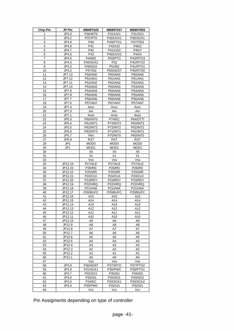
Chip Pin JP Pin MB89T625 MB89T637 MB89T8551 JP3.3 P36/WT0 P31/UO1 P31/SO12 JP3.2 P37/PT0 P30/UCK1 P30/SCK13 JP4.9 P40 P43/PTO1 P47/TRG4 JP4.8 P41 P42/UI2 P46/Z5 JP4.7 P42 P41/UO2 P45/Y6 JP4.6 P43 P40/UCK2 P44/X7 JP4.5 P44/BZ P53/PTO P43/RTO38 JP4.4 P45/SCK2 P52 P42/RTO29 JP4.3 P46/SO2 P51/BZ P41/RTO110 JP4.2 P47/SI2 P50/ADST P40/RTO011 JP7.13 P50/AN0 P60/AN0 P50/AN012 JP7.12 P51/AN1 P61/AN1 P51/AN113 JP7.11 P52/AN2 P62/AN2 P52/AN214 JP7.10 P53/AN3 P63/AN3 P53/AN315 JP7.9 P54/AN4 P64/AN4 P54/AN416 JP7.8 P55/AN5 P65/AN5 P55/AN517 JP7.7 P56/AN6 P66/AN6 P56/AN618 JP7.6 P57/AN7 P67/AN7 P57/AN719 JP7.4 Avcc Avcc Avcc20 JP7.3 Avr Avr Avr21 JP7.1 Avss Avss Avss22 JP5.3 P60/INT0 P74/EC P64/DTTI23 JP5.4 P61/INT1 P73/INT3 P63/INT324 JP5.5 P62/INT2 P72/INT2 P62/INT225 JP5.6 P63/INT3 P71/INT1 P61/INT126 JP5.7 P64 P70/INT0 P60/INT027 JP5.9 RST RST RST28 JP2 MOD0 MOD0 MOD029 JP1 MOD1 MOD1 MOD130 X0 X0 X031 X1 X1 X132 Vss Vss Vss33 JP12.24 P27/ALE P27/ALE P27/ALE34 JP12.23 P26/RD P26/RD P26/RD35 JP12.22 P25/WR P25/WR P25/WR36 JP12.21 P24/CLK P24/CLK P24/CLK37 JP12.20 P23/RDY P23/RDY P23/RDY38 JP12.19 P22/HRQ P22/HRQ P22/HRQ39 JP12.18 P21/HAK P21/HAK P21/HAK40 JP12.17 P20/BUFC P20/BUFC P20/BUFC41 JP12.16 A15 A15 A1542 JP12.15 A14 A14 A1443 JP12.14 A13 A13 A1344 JP12.13 A12 A12 A1245 JP12.12 A11 A11 A1146 JP12.11 A10 A10 A1047 JP12.10 A9 A9 A948 JP12.9 A8 A8 A849 JP12.8 A7 A7 A750 JP12.7 A6 A6 A651 JP12.6 A5 A5 A552 JP12.5 A4 A4 A453 JP12.4 A3 A3 A354 JP12.3 A2 A2 A255 JP12.2 A1 A1 A156 JP12.1 A0 A0 A057 Vss Vss Vss58 JP3.9 P30/ADST P37/WTO P37/PTO259 JP3.8 P31/SCK1 P36/PWC P36/PTO160 JP3.7 P32/SO1 P35/SI1 P35/SI261 JP3.6 P33/SI1 P34/SO1 P34/SO262 JP3.5 P34/EC P33/SCK1 P33/SCK263 JP3.4 P35/PWC P32/UI1 P32/SI164 Vcc Vcc Vcc
Pin Assigments depending on type of controller

page -42-
7.2. Appendix B: Example Program Listings
Example Listing "LED8L.C"
/*=====================================================================*//* F U J I T S U *//* *//* M i k r o e l e k t r o n i k G m b H *//* *//* *//* Filename: LED8L.C *//* Description: LEDs flashing on eva-board *//* Series: MB89630 *//* Version: V02.00 *//* Design: Markus Mierse '97 *//*=====================================================================*/
/* from FETOOL\8L\INCLUDE-directory : */#include <TYPEDEFS.H> /* some usefull type definitions */
/* some example definitions : *//* "direct"-variables stored directly in */
direct BYTE DirVarByte; /* lower RAM (DIRVAR) for faster access */direct BYTE DirInitByte = 0; /* initialized direct variable (DIRINIT) */
BYTE VarByte; /* standard variables stored in DVAR */BYTE InitByte = 0; /* initialized (DINIT) */const int constdummy = 0; /* Constant definition */BYTE *LED1 = 0x0AE2; /* Pointers to the LEDs (memory mapped) */BYTE *LED2 = 0x0AE3;
/*=====================================================================*//* Prototypes */void wait(int counter);
/*=====================================================================*//* Main Module */
void main (void){ while(1) { *LED1=1; *LED2=0; wait(1000); *LED1=0; *LED2=1; wait(1000); *LED1=1; *LED2=1; wait(1000); *LED1=0; *LED2=0; wait(1000); }}/*======================================================================*/void wait(int counter){ for (; counter > 0; counter--); /* very simple delay loop */}

page -43-
Example Listing "BIOSDEMO.C"
/*=====================================================================*//* F U J I T S U *//* *//* M i k r o e l e k t r o n i k G m b H *//* *//* *//* Filename: BIOSDEMO.C *//* Description: Demostration for evaluation board BIOS-functions *//* After downloading, start a terminal and execute *//* program by typing 'g' or push user reset button *//* Version: V02.00 *//* Design: Markus Mierse '97 *//*=====================================================================*/
/* from FETOOL\8L\INCLUDE-directory : */#include <evabios.h> /* BIOS-fctns; includes also TYPEDEFS.h */
/* some dummy definitions : */direct BYTE DirVarByte; /* to avoid linker warnings (DIRVAR) */direct BYTE DirInitByte = 0; /* initialized direct variable (DIRINIT) */BYTE VarByte; /* standard variables stored in DVAR */BYTE InitByte = 0; /* initialized (DINIT) */const int constdummy = 0; /* Constant definition */BYTE InpStr[82];BYTE SumB;WORD SumW;
/* ROM-constant strings */CSTR IniMsg[] = "\n"
"***************************************\n""** Demonstration of BIOS Functions **\n""***************************************\n";
CSTR StrMsg[] = "'puts'-function :\n"" This is an output string\n\n""'gets'-function :\n"" Please enter your name : ";
CSTR TyMsg[]= "\n Thank you, ";CSTR ChGMsg[]= "\n\n'getch'-function :\n"
" Press any key !\n ";CSTR OcMsg[]= "\n You pressed ";CSTR ChPMsg[]= "\n\n'putch'-function : ";CSTR HexBMsg[]= "\n\n The byte-check sum is : ";CSTR HexWMsg[]= "\n The word-check sum is : ";CSTR EndMsg[]= "\n\n That all folks ! Press any key for Monitor Reset";
/*=====================================================================*/void wait(int counter);
/*=====================================================================*//* Main Module */void main(){ int ix; BYTE Ch1, Ch2;
puts(IniMsg); /* Print header */puts(StrMsg); /* Put String */gets(&InpStr); /* Input String */puts(TyMsg);puts(InpStr); /* print received string */puts(ChGMsg);Ch1 = getch(); /* Input Charakter */puts(OcMsg);

page -44-
putch(Ch1); /* Output received Char */puts(ChPMsg);
ix = 0;while (InpStr[ix]) /* go through string */{ Ch2 = InpStr[ix]; /* type every single char */ putch(Ch2); putch(32); wait(3000); /* slowly...*/ SumB += Ch2; /* calculate the checksum */ SumW += Ch2; ix++; /* next char */}puts(HexBMsg); /* print the checksum */printHexByte(SumB); /* in byte-format */puts(HexWMsg);printHexWord(SumW); /* and in word-format */
puts(EndMsg); /* final message */getch();MonitorReset (); /* monitor-reset the board */
}
/*=====================================================================*//* Procedures */
void wait(int counter){ for (; counter > 0; counter--); /* very simple delay loop */}
Header File "EvaBIOS.h"
/*+---------------------------------------------------------------------+*//*¦ F U J I T S U ¦*//*¦ ¦*//*¦ M i k r o e l e k t r o n i k G m b H ¦*//*¦ ¦*//*¦ Filename: EvaBIOS.H ¦*//*¦ Description: Header file for EVA Board I/O Functions ¦*//*¦ Series: Independent ¦*//*¦ Version: V01.00 ¦*//*¦ Design: Edmund Bendels 09.08.94 ¦*//*+---------------------------------------------------------------------+*/
#include <TYPEDEFS.H>
void MonitorReset ();BYTE getch ();void putch (BYTE c);BYTE *gets (BYTE *s);void puts (const BYTE *s);void printHexByte (BYTE b);void printHexWord (WORD w);

page -45-
Library File "EvaBIOS.C"
/*+---------------------------------------------------------------------+*//*¦ F U J I T S U ¦*//*¦ ¦*//*¦ M i k r o e l e k t r o n i k G m b H ¦*//*¦ ¦*//*¦ Filename: EvaBIOS.C ¦*//*¦ Description: Some functions to access the MB89637 EVA Board ¦*//*¦ Series: Independent ¦*//*¦ Version: V01.00 ¦*//*¦ Design: Jürgen Suppelt 09.03.94 ¦*//*¦ Edmund Bendels 09.08.94 ¦*//*+---------------------------------------------------------------------+*/
#include "evabios.h"
char (*BiosCall) (int, int) = 0x080C;void (*MonReset) (void) = 0x0818;
BYTE *LED1 = 0x0AE2;BYTE *LED2 = 0x0AE3;
BYTE getch (){ return (BiosCall (0x0200, 0));}
BYTE *gets (BYTE *s){ BiosCall (0x0400 | 0xD2, s); /* CrLf after Input, Max 82 Char */ return (s);}
void putch (BYTE c){ BiosCall(0x0100 | c, 0);}
void puts (const BYTE *s){ BiosCall (0x0300, s);}
void printHexByte (BYTE b){ BiosCall (0x0500 | b, 0);}
void printHexWord (WORD w){ BiosCall (0x0600, w);}
void MonitorReset (){ MonReset ();}

page -46-
Example Listing "NEWPROJ.C"
/*=====================================================================*//* F U J I T S U *//* *//* M i k r o e l e k t r o n i k G m b H *//* *//* *//* Filename: NEWPROJ.C *//* Description: Example-project for 8L-evaluation board *//* Series: MB89630 *//* Version: V01.00 *//* Design: Markus Mierse '97 *//*=====================================================================*/
/* from FETOOL\8L\INCLUDE-directory : */#include <TYPEDEFS.H> /* some usefull type definitions */#include <MB89630.H> /* register definitions for 630-family */#include <INT89630.H> /* interrupt definitions for 630-family */
/* some example definitions : *//* "direct"-variables stored directly in*/
direct BYTE DirVarByte; /* lower RAM (DIRVAR) for faster access */direct BYTE DirInitByte = 0; /* initialized direct variable (DIRINIT)*/
BYTE VarByte; /* standard variables stored in DVAR */BYTE InitByte = 0; /* initialized (DINIT) */const int constdummy = 0; /* Constant definition */
BYTE *LED1 = 0x0AE2; /* Pointers to the LEDs (memory mapped) */BYTE *LED2 = 0x0AE3;
/*=====================================================================*/
/* Prototypes */
/*=====================================================================*/
/* Main Module */
void main (void){
}
/*=====================================================================*//* Procedures */
/*=====================================================================*//* Interrupt service routines */
#pragma interrupt#pragma save_reg void WATCHINT11(){} void TBCINT10(){} void ADCINT9(){} void UART_T_INT8(){} void UART_R_INT7(){} void TC16INT6() {} void PWCINT5(){} void PWM2INT4(){} void PWM1INT3(){} void SIOINT2(){} void EXINT1(){} void EXINT0(){}#pragma nointerrupt#pragma nosave_reg
page -47-
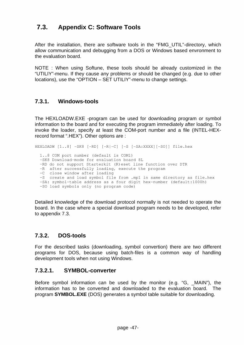
7.3. Appendix C: Software Tools
After the installation, there are software tools in the “FMG_UTIL”-directory, whichallow communication and debugging from a DOS or Windows based envronment tothe evaluation board.
NOTE : When using Softune, these tools should be already customized in the“UTILIY”-menu. If they cause any problems or should be changed (e.g. due to otherlocations), use the “OPTION – SET UTILIY”-menu to change settings.
7.3.1. Windows-tools
The HEXLOADW.EXE -program can be used for downloading program or symbolinformation to the board and for executing the program immediately after loading. Toinvoke the loader, specify at least the COM-port number and a file (INTEL-HEX-record format “.HEX”). Other options are :
HEXLOADW [1..8] -SK8 [-RD] [-R|-C] [-S [-SA:XXXX][-SO]] file.hex
1..8 COM port number (default is COM1) -SK8 Download-mode for evaluation board 8L -RD do not support Starterkit (R)eset line function over DTR -R after successfully loading, execute the program -C close window after loading -S create and load symbol file from .mp1 in same directory as file.hex -SA: symbol-table address as a four digit hex-number (default:1000h) -SO load symbols only (no program code)
Detailed knowledge of the download protocol normally is not needed to operate theboard. In the case where a special download program needs to be developed, referto appendix 7.3.
7.3.2. DOS-tools
For the described tasks (downloading, symbol convertion) there are two differentprograms for DOS, because using batch-files is a common way of handlingdevelopment tools when not using Windows.
7.3.2.1. SYMBOL-converter
Before symbol information can be used by the monitor (e.g. “G, _MAIN”), theinformation has to be converted and downloaded to the evaluation board. Theprogram SYMBOL.EXE (DOS) generates a symbol table suitable for downloading.
page -48-
To execute the program, specify the mapping information, generated by the linker(.MP1), an output file (.SYM) which needs to be downloaded after the conversionand an address in memory where the table should be located e.g. 1000hex (normallyfree RAM). The offset for suppressing a certain range is optional.
SYMBOL <InFile> <OutFile> <StartOfHex> [<StartOfSymbols>]
example1: SYMBOL test.mp1 test_s.hex 1000 locates the HEX-file at 0x1000h with all symbols
example2: SYMBOL test.mp1 test_s.hex 1000 80 locates the HEX-file at 0x1000h with symbols starting from 0x80h (suppress symbols in the range of [0..0x7Fh]
7.3.2.2. HEXLOAD for DOS
The download-utility for the DOS-environment is call HEXLOAD.EXE. Usage issimilar to the described HEXLOADW.EXE, but with different options :
HEXLOAD [1..8] [-N|-NN] [-D] [-R] file.hex
1..8 COM port number (default is COM1) -N do (N)ot display the record lines, show percentage counter -NN do (N)ot display process indicator at all (recomm. for Softune) -R do Not support Starterkit (R)eset line function over DTR -D (D)ebug mode display all received characters
7.3.2.3. Terminal for DOS
A very simple terminal program “MT.COM” with default communication andemulation settings for the evaluation board is provided. This DOS-program uses theassigned COM-port (use the mode-command to assign a COM-port - e.g. “modecom1: 9600,n,8,2”).

page -49-
7.3.3. Download Protocol
Three different formats can be used to download data to the evaluation board :
1.) Object code hex-lines (as produced by the linker *.hex file extension)
e.g. :10200000FFEEDDCCBBAA99887766554433221100F8↵
can be entered as a command. The ':' is interpreted as a download command andthe specified data will be transferred into memory. The correct format and checksumare not checked ! Note that a download program using this mechanism must readeach character's echo and that the completing CR is echoed as CR LF.
2.) HexFile Download function - works similar as the previous command, however :a) download function is activated by sending the command 'HEXDWL↵b) Note that the characters of the command are echoed, the CR is not !c) a hex-line is transferred (but no character is echoed !)d) when the monitor has processed the hex-line, it will send the acknowledge
character (06H).e) then the next hex-line can be transferred.f) The hex download function terminates automatically if a hex-line containing an
'end' mark (hex-line with zero byte count) was downloaded.g) A checksum is built over each line and the monitor will respond with a not-
acknowledge character (05H) if an error occurs.
3.) The High Speed Download function is also activated by a special command('HSDWL').(Note that the characters of the command are echoed, the CR is not ! )In the following sequence, addresses, total byte counts and the data bytes aretransferred as binary characters and are not echoed. The protocol can be illustratedas :
PC Download Program Monitor Operation
a) send 'HSDWL↵' echo each character (not the CR)b) send the Request Character 0xEBc) send the Record Header 0xBE or a Termination 0DH char to exit the download functiond) send Address Bytes (Hi,Lo) send Byte Count (Hi,Lo)e) send Data Bytes (the monitor will store the data)f) continue at b. (at the specified locations)

page -50-
7.4. Appendix D: Monitor Software Notes, Restrictions
As mentioned in chapter 2, the Monitor software resides in an EPROM memory bankin the upper address area 8000h-FFFFh . It is transparent to the upper User RAMbank. In addition, some User RAM locations are reserved for monitor variables.
Monitor reserved RAM sections are:a) A small section in the lower User RAM area (0800h-0FFFh).This section is used for some special RAM code procedures which are copied fromthe EPROM during the monitor initialisation.It also contains the BIOS interface table, monitor variables, and the off-chip memorymapped IO registers.b) The vector table entry for the CALLV #7 instruction, (UserRAMAddress: FFCE-FFCF) which is initialised with a vector to a special RAM codesection, supporting breakpoints and single step.
Apart from these reserved RAM areas, the user can utilise the on-chip/off-chip RAMand on-chip peripherals for his programming and evaluation requirements.
Other restrictions:
1.) Monitor BIOS InterfaceWhen using BIOS interface functions (Chap.4,P. 23 and following), the processorstack area must be in the address range 0000h..1FFFh excluding the reserved area0800h..0FFFh (Chap.7.4, P 56). Thus, the stack must be within 0000h..07FF or1000..1FFFh.
2.) Single Stepping certain code sequences:Due to the implementation of the single step mechanism, the following assembler-code constructions can not be single stepped:
Conditional Branch to the same or following address Use constructs like:
e.g. LABEL1: BBC 10:3,LABEL1 LABEL: NOPBBC 10:3,LABEL
BNC FOLLAe.g. FOLLA: xxx yyy,zzz BNC FOLLA
FOLLA: xxx yyy,zzz
Return from Interrupt : do not single step the RETI instruction !
3.) Processor Speed, Power Management FunctionsWhen developing programs which utilise or activate special on-chip registers, beaware that the monitor generally disables interrupts when it is active.Note also that switching the micro controller into the STOP or SLEEP modes willdisable monitor control via the terminal.When the monitor is active, it always configures the clock control for max. speed.The user program speed is saved and restored when control is given to the userprogram.

page -51-
7.5. Appendix E: List of development tools
MB89620 family
§ Emulator for the F2MC-8L Family Emulation Unit MSE1001C§ Emulator for the F2MC-8L Family Power Supply PS5V1_2A0§ Evaluation Chip MB89PV620C-SH§ Piggyback-EPROM MBM27C256A-20CZ (or compatible)§ Probe cable MSE2144-201 (optional)§ OTP MB89P625/7/9P-SH§ Programmable MCU MB89W625/7C-SH§ OTP Programming Adapter ROM-64SD-28DP-8L
MB89630 family
§ Emulator for the F2MC-8L Family Emulation Unit MSE1001C§ Emulator for the F2MC-8L Family Power Supply PS5V1_2A0§ Evaluation Chip MB89PV630C-SH§ Piggyback-EPROM MBM27C256A-20CZ (or compatible)§ Probe cable MSE2144-201 (optional)§ OTP MB89P637P-SH§ Programmable MCU MB89W637C-SH§ OTP Programming Adapter ROM-64SD-28DP-8L
MB89850 family
§ Emulator for the F2MC-8L Family Emulation Unit MSE1001C§ Emulator for the F2MC-8L Family Power Supply PS5V1_2A0§ Probe header MB2144-212-01A§ OTP Adapter MSE1036§ OTP MB89P857P-SH§ Programmable MCU MB90W857C-SH§ OTP Programming Adapter ROM-64SD-28DP-8L
page -52-
8. Index
Activate Symbols, 23ANSI terminal, 20AS, 23
BIOS I/O examples, 16BIOSDEMO, 16break point, 15BreakpointAddress, 30BreakpointNumber, 30Build-button, 13
CALL Subroutine, 28CALLV #7, 32, 54C-compiler, 29C-compiler, Assembler and Linker, 19Clear Breakpoint, 31Command Input, 20Commands, 20communication parameters, 6communication parameters, 20Compare Memory, 27Control Register Map, 43control registers, 10CPU registers, 35
Data RAM, 43DEC, 23Default Input Mode, 23develop software, 17Disable Breakpoints, 31download, 51download data, 53DTR signal, 6Dump Memory, 25
Edit Byte, 27Edit Data, 27edit functions, 20Edit Word, 27Erase Symbol Table, 24ES, 24Evaluation Board, 5, 10Evaluation Board Hardware, 40Evaluation Board Recourses, 10Examples using Softune, 11External memory mapped IO, 43external microprocessor bus, 43
Fill, 26Function Call, 35Function Calls Parameter Passing, 35
GAL, 43Go, 28GO, 15
Help, 23HEX, 23

page -53-
HEX numbers, 21HexFile Download, 52HEXLOAD.EXE, 52HEXLOADW.EXE, 51
I/O Function Calls, 35initial file, 17install, 6Installation, 6Introduction, 5IO ports, 10IO-definitions, 19IO-registers, 17
jumpers, 45
Listing "BIOSDEMO.C", 47Listing "LED8L.C", 46Listing "NEWPROJ.C", 50loader, 51
mapping information, 52MB89P637, 43MB89T625, 43member list, 11memory map, 10, 18Memory map, 43memory-map, 19Monitor, 5Monitor BIOS Interface, 33Monitor Commands, 22Monitor Control, 39Monitor LED, 20Monitor Operation, 20Monitor Reset, 29, 39monitor software, 10Monitor Software Notes, Restrictions, 54monitor variables, 10monitor-debug functions, 14Move Memory, 26MRES, 43
Number Formats, 21
OccurCount, 30OccurCounter function, 15
PAL, 43parameters, 21PC terminal, 20Pin Assignment, 40Print Register Values, 39Processor specific, 19PROM, 5prompt, 14
RD, 43RESET VECTOR, 29
Search, 26Set Break Point, 30setup, 6

page -54-
Show Registers, 28Snapshot, 30Snapshot, 30Stack Dump, 25, 26sub-clock, 42symbol, 21symbol file, 14Symbol Information, 23, 24symbol names, 23SYMBOL.EXE, 51SymTab Vector, 39
TargetAddress, 26Technical Characteristics, 9TERM, 24tools, 51trace, 14Trace Instruction, 31TS, 23
URES, 43User Program Call, 28, 29User Program Reset, 29User Program Start, 39User Reset button, 6Utility-menu, 13
V, 24
WR, 43