f(~4 - nasa
TRANSCRIPT
f(~4
NASA TECHNICALMEMORANDUM
NASA TM X-64685Volume I of IV
' (NASA-TM-X-64685-Vol-1) MANUFACTURE ANDQUALITY CONTROL OF INTERCONNECTING WIREHARWNESSES, VOLUME 1 (NASA) 1 Sep. 1972;3~ QO 9~--0 ~ jCSCL 09E
MANUFACTURE AND QUALITY CONTROLOF INTERCONNECTING WIRE HARNESSES
September 1, 1972
NASA
G3/09
N72-33206
Unclas43774
George C.Marshall
Marshall
Space FlightSpace Flight
Center,Center
A labama
MSFC - Form 3190 (Rev June 1971)
TECHNICAL REPORT STANDARD TITLE PAGE
1. REPORT NO. 2. GOVERNMENT ACCESSION NO. 3. RECIPIENT'S CATALOG NO.
NASA TMX-64685
4. TITLE AND SUBTITLE 5. REPORT DATE
September 1, 1972Manufacture and Quality Control of Interconnecting 6. PERFORMING ORGANIZATION CODE
Wire Harnesses Volume I of IV.7. AUTHOR(S) 8.PERFORMING ORGANIZATION REPORrT
MSFC AD HOC Committee9. PERFORMING ORGANIZATION NAME AND ADDRESS 10. WORK UNIT NO.
NASA - George C. Marshall Space Flight Center 11. CONTRACT OR GRANT NO.Marshall Space Flight Center, Alabama 35812
13. TYPE OF REPORT & PERIOD COVERED
12. SPONSORING AGENCY NAME AND ADDRESS
NASA TechnicalNational Aeronautics and Space Adminstration MemorandumWashington, D.C. 20546 14. SPONSORING AGENCY CODE
15. SUPPLEMENTARY NOTES
Prepared under the overall direction of the Quality and Reliability AssuranceLaboratory
16. ABSTRACT This document has been prepared for use as a standard for manufacture, instal-lation, and quality control of eight types of interconnecting wire harnesses. It is madeup of four volumes under one reference number to simplify control and referral on con-tracts. Each volume can be independently employed should only harnesses within onevolume be of interest. The processes, process controls, and inspection and test require-ments reflected are based on (a) acknowledgment of harness design requirements definedin MSFC document 40M39582, "Harness, Electrical Design Standard," (b) acknowledgment ofharness installation requirements defined in MSFC-SPEC-494, "General Specification forInstallation of Harness Assembly (Electrical Wiring), Space Vehicle," (c) identificationof the various parts, materials, etc, utilized in harness manufacture, and (d) formula-tion of a typical manufacturing flow diagram for identification of each manufacturingand quality control process, operation, inspection, and test.
The document covers interconnecting wire harnesses defined in the design standard.Volume I covers type I, enclosed in fluorocarbon elastomer convolute, tubing; type II,enclosed in TFE convolute tubing lined with fiberglass braid; type III, enclosed in TFEconvolute tubing; type V, combination of types III and IV: Volume II covers type IV,open bundle (not enclosed): Volume III covers type VI, enclosed in TFE heat shrinktubing; type VII, flexible armored: and Volume IV covers type VIII, flat conductor cable.Volume breadth covers installations of groups of harnesses in a major assembly and theassociated post installation inspections and electrical tests. All vol's are TM X-64685.
Knowledge gained through experience on the Saturn V Program coupled with recent advancesin techniques, materials, and processes have been incorporated into this document.
17. KE'Y WORDS 18. DISTRIBUTION STATEMENT
Unlimited - UnclassifiedSpace Vehicle WiringInterconnecting WiringHarness Design .A.Harness FabricationHarness Inspection John M. Knadler, III, Technical MonitorHarness Installation Task 2026-TA-15
19. SECURITY CLASSIF. (of this repor) 20. SECURITY CLASSIF. (of this page) 21. NO. OF PAGES 22. PRICE
209
Unclassified Unclassified /2 ·MSFC - Form 3292 (May 1969) i

PREFACE
Throughout the Saturn Program, refinements in interconnecting wire harness
designs, manufacturing and installation techniques, and inspection and testing
requirements were implemented to achieve optimum reliability in space vehicle
and payload electrical systems. The preparation of this document was under-taken to assure such learning as was afforded by the Saturn Program is made
available for future programs. This information was further supplementedwith inclusion of recent advancements made in harness designs, manufacturing
techniques, etc.
Under the direction of Mr. Richard G. Smith, MSFC Saturn Program Manager,
the responsibility for providing overall direction was assigned to the Quality
and Reliability Assurance Laboratory, MSFC with the task of preparing the
document assigned to North American Rockwell Corporation, Space Division.
The task was formally defined as three subtasks:
(a) Update of harness design Standard 40M39582,
(b) Update of harness installations design Specification
MSFC-SPEC-494, and
(c) Derivation of the manufacturing and quality controlprocesses volumes.
Formation of an AD HOC committee, comprised of representatives of MSFC
Science and Engineering Laboratories (Astrionics, Astronautics, Process
Engineering, and Quality and Reliability Assurance) for technical guidance,
assured unity of input and compatibility between documents.
The task, as defined in Task Authorization 15 (TA 15) dated April 13, 1972,
and amended by TA 15 Cl, dated January 11, 1972, issued to North American
Rockwell Corporation, Space Division, pursuant to NASA contract NAS7-200,was completed with delivery of report SA72-SA-0060 on July 31, 1972. TheNorth American Rockwell Corporation Study Manager was Mr. W. L. Malohn,directly assisted by Messrs. J. Vandergriff, R. H. Parker, and E. J.Stringer.
('C

FOREWORD
This document is one of a series of four volumes prepared for use
as a standard for manufacturing and quality control of interconnecting
wire harnesses for space vehicle and payload applications.
The procedures reflected herein are based on the following four key
elements:
1. Formulation of a typical manufacturing flow diagram for identi-
fication of each manufacturing and quality control process,
operation, inspection and test point.
2. Identification of the various parts, materials, tools, and
components, utilized in harness manufacture.
3. Acknowledgement of design standards as defined in MSFC document
40M39582, "Harness, Electrical Design Standard".
4. Acknowledgement of harness assembly installation standards defined
in bISFC-SPEC-494, "General Specification for Installation of
Harness Assembly (Electrical Wiring), Space Vehicle".
The complete series of documents covers the following harness types:
Enclosed in
Enclosed in
Enclosed in
Combination
fluorocarbon elastomer convolute tubing
TFE convolute tubing lined with fiberglass braid
TFE convolute tubing
of Type III and Type IV
Volume II
Type IV Open bundle (not enclosed)
Volume IIIType VI Enclosed in TFE heat shrink tubing
Type VII Flexible armored
Volume IVType VIII Flat conductor cable
- iii -
Volume I
Type
Type
Type
Type
I
II
III
V

VOLUME I
CONTENTS
Section Page
1 INTRODUCTION 1-1
2 MFG. FLOW DIAGRAMS 2-1
3 RECEIVING INSPECTION 3-1
4 WIRE AND CABLE CUTTING 4-1
5 TEMPORARY WIRE AND CABLE IDENTIFICATION 5-1
6 WIRE AND CABLE LAYOUT 6-1
7 HARNESS SECURING 7-1
8 STRIPPING ELECTRICAL WIRE AND CABLE 8-1
9 CABLE SHIELD TERMINATION 9-1
10 TW.T AND CABtL TERMINATION 10-1
11 CONNECTOR ASSEMBLY 11-1
12 POTTING ENCAPSULATION 12-1
13 APPLICATION OF SHIELDED BRAID 13-1
14 APPLICATION OF FIBERGLASS BRAID 14-1
15 APPLICATION OF CONVOLUTE TUBING 15-1
16 HARNESS IDENTIFICATION 16-1
17 HARNESS CLEANING 17-1
18 HARNESS HANDLING, PACKAGING AND SEALING 18-1
19 HARNESS INSTALLATION 19-1
20 SUPPORT AND CLAMPING 20-1
21 CONNECTOR MATING 21-1
22 TEST 22-1
23 POST INSTALLATION VERIFICATION 23-1
iv

CONTENTS
Section
1.0 INTRODUCTION1.1 SCOPE1.2 APPLICABILITY
1.2.1 Applicable Documents1.3 DEFINITIONS
1.3.1 Type I Harness1.3.2 Type II Harness1.3.3 Type III Harness1.3.4 Type V Harness1.3.5 Wire1.3.6 Cable1.3.7 Shielding1.3.8 Convolute Tubing
2.0 MANUFACTURING FLOW DIAGRAMS2.1 SCOPE2.2 APPLICABILITY
3.0 RECEIVING INSPECTION3.1 GENERAL3.2 SCOPE3.3 PURPOSE3.4 REQUIREMENTS
3.4.1 Certification of Conformance Report3.4.2 Sampling for Acceptance3.4.3 Examination of Materials3.4.4 Facilities
3.5 WIRE AND CABLE3.5.1 Visual Examination3.5.2 Electrical Tests
3.6 ELECTRICAL CONNECTORS3.7 POTTING MATERIALS3.8 INSULATION SLEEVING3.9 COAXIAL CABLE3.10 CONDUCTOR AND SHIELD TERMINATIONS3.11 SOLDER AND SOLDER FLUX3.12 TIE-CORD MATERIAL3.13 CONVOLUTE TUBING3.14 CONVOLUTE FITTINGS, ADAPTERS, AND TRANSITIONS3.15 WIRE/CABLE SUPPORT CLAMPS3.16 METALLIC BRAID WIRE/WOVEN BRAID WIRE3.17 OTHER ASSOCIATED MATERIALS
4.0 WIRE AND CABLE CUTTING4.1 GENERAL4.2 PROCESS CONTROL REQUIREMENTS
4.2.1 Cleanliness4.2.2 Equipment/Tool Requirements
v

Section
4.3 WIRE/CABLE CUTTING OPERATIONS
5.0 TEMPORARY WIRE AND CABLE IDENTIFICATION5.1 GENERAL5.2 PROCESS CONTROL REQUIREMENTS5.3 IDENTIFICATION METHODS5.4 LEGIBILITY
6.0 WIRE AND CABLE LAYOUT6.1 GENERAL6.2 PROCESS CONTROL REQUIREMENTS
6.2.1 Control and Cleanliness of Mockup Areas6.2.2 Wire and Cable Protection
6.3 FABRICATION AND HANDLING PRECAUTIONS6.3.1 Cleanliness Precautions
6.4 LAYOUT6.5 TWISTED LAY OF WIRE/CABLE BUNDLES
6.5.1 Twisted Lay Procedure6.5.2 Harness Branch Breakout Procedure
6.6 BEND RADIUS6.7 INSPECTION
7.0 HARNESS SECURING7.i GENERAL7.2 REQUIREMENTS
7.2.1 Process Controls7.2.2 Securing Methods
7.3 SECURING INTERVALS7.4 CONTINUOUS LACED METHOD
7.4.1 Lacing Material7.4.2 Lacing Procedure7.4.3 Lacing Cord Splice Termination7.4.4 Lacing Branches and Breakouts7.4.5 Acceptable Lacing Criteria
7.5 SPOT TIED METHOD7.5.1 Procedure7.5.2 Acceptable Spot Tie Criteria
7.6 TYING CORD REMOVAL
8.0 STRIPPING ELECTRICAL WIRE AND CABLE8.1 GENERAL8.2 PROCESS CONTROL REQUIREMENTS
8.2.1 General Process Acceptance Criteria8.2.2 Method Selection8.2.3 Tool Approval and Handling8.2.4 Operator Qualification8.2.5 Cleanliness
8.3 THERMAL STRIPPING8.3.1 Equipment Requirements8.3.2 Thermal Stripping Procedure
vi
Section
8.4 MECHANICAL STRIPPING8.4.1 Tool Requirements8.4.2 Tool Control
8.5 STRIPPING LARGE WIRES AND SHIELDED CABLES8.6 STRIPPING COAXIAL CABLES
9.0 CABLE SHIELD TERMINATION9.1 GENERAL9.2 REQUIREMENTS
9.2.1 Process Control Requirements9.3 CLASSIFICATION AND METHODS9.4 SHIELD TERMINATING
9.4.1 Insulation Stripping9.4.2 Location9.4.3 Shield Braid Cutting
9.5 TERMINATION OF FLOATING (UNGROUNDED) SHIELDED CABLES9.6 SHIELD RETURN WIRES
9.6.1 Length of Shield Return Wires9.6.2 Attachment of Shield Return Wires
9.7 SHIELD TERMINATION INSULATION9.7.1 Application of Insulation Sleeves
9.8 GROUNDED SHIELD TERMINATION METHODS9.9 TWO-PIECE CRIMPED FERRULE METHODS
9.9.1 Crimping Tools9.9.2 Standards for Crimped Shield Termination9.9.3 Braided Shield Method9.9.4 Folded and Combed Shield Termination Method9.9.5 Single-Fold Method9.9.6 Terminating Two or More Individually Terminated
Shields to a Common Point9.10 SOLDER SLEEVE FERRULE METHODS
9.10.1 Application of Solder Sleeve Ferrules9.10.2 Nominal Solder Sleeve Shield Coverage Method9.10.3 Maximum Solder Sleeve Shield Coverage Method9.10.4 Examination of Completed Solder Sleeve
10.0 WIRE AND CABLE TERMINATION10.1 GENERAL10.2 PROCESS CONTROL REQUIREMENTS
10.2.1 Cleanliness Requirements10.2.2 Operator Qualifications10.2.3 Process Verification
10.3 CRIMP CONTACT TERMINATIONS10.3.1 Crimp Tooling10.3.2 Calibration and Control of Crimping Tools10.3.3 Crimped Contact Termination Preparation10.3.4 Crimping Procedure10.3.5 Crimp Termination Process Verification
10.4 SOLDER CONTACT TERMINATIONS10.4.1 Soldering Equipment and Materials
vii

Section
10.4.2 Wire Preparation10.4.3 Connector Preparation10.4.4 Joining Wire/Cable to Connector10.4.5 Soldered Contact Process Verification
11.0 CONNECTOR ASSEMBLY11.1 GENERAL11.2 PROCESS CONTROL REQUIREMENTS
11.2.1 Connector Protection11.2.2 Connector Cleaning
11.3 ASSEMBLY OF CRIMP TYPE CONNECTORS11.3.1 Contact Insertion (Rear Entry Type)11.3.2 Contact Insertion (Front Entry Type)11.3.3 Sealing of Unused Connector Grommet Holes11.3.4 Backshell Installation11.3.5 Strain Relief or Cable Guide Types11.3.6 Tightening Connectors11.3.7 Crimp Type Connector Process Verification
11.4 ENVIRONMENTALLY SEALED SOLDER TYPE CONNECTORS11.4.1 Wire/Cable Installation11.4.2 Soldering of Wires/Cables11.4.3 Connector Assembly11,o44 Solder Type Connector Process Verification
11.5 ASSEMBLY OF COAXIAL CONNECTORS11.5.1 Coaxial Type Connector Process Verification
12.0 POTTING ENCAPSULATION12.1 GENERAL12.2 PROCESS CONTROL REQUIREMENTS
12.2.1 Control and Cleanliness of Potting Facility12.2.2 Equipment12.2.3 Handling Precautions
12.3 HARNESS PREPARATION12.4 POTTING COMPOUND PREPARATION12.5 POTTING REQUIREMENTS12.6 EXAMINATION OF POTTING
13.0 APPLICATION OF SHIELDED BRAID13.1 GENERAL13.2 PURPOSE13.3 PROCESS CONTROL REQUIREMENTS
13.3.1 Process Control13.4 SHIELDED BRAID CONSTRUCTION13.5 APPLICATION OF SHIELD BRAID
13.5.1 Examination of Applied Shield Braiding13.6 SHIELD TERMINATION ADAPTERS13.7 TERMINATION OF SHIELD BRAID (TYPE II HARNESSES)13.8 TERMINATION OF SHIELD BRAID (TYPE III HARNESSES)13.9 SHIELD TERMINATION PROCESS VERIFICATION
viii

Section
14.0 APPLICATION OF FIBERGLASS BRAID14.1 GENERAL14.2 PURPOSE14.3 PROCESS CONTROL REQUIREMENTS
14.3.1 Pre-Process Control (Fiberglass Braid Without MetallicShield Braid)
14.3.2 Pre-Process Control (Fiberglass Braid over Metallic ShieldBraid)
14.4 FIBERGLASS BRAID CONSTRUCTION14.5 APPLICATION OF BRAID JACKET
14.5.1 Examination of Applied Braiding14.6 BRAID TERMINATION ADAPTERS14.7 TERMINATION OF PROCEDURE FOR HARNESSES WITH FIBERGLASS
BRAID AND METALLIC SHIELD BRAID14.8 TERMINATION PROCEDURE FOR HARNESSES WITH FIBERGLASS
BRAID ONLY14.9 BRAID TERMINATION PROCESS VERIFICATION
15.0 APPLICATION OF CONVOLUTE TUBING15.1 GENERAL15.2 PROCESS CONTROL REQUIREMENTS
15.2.1 Process Control - Type I Harness Assemblies15.2.2 Process Control - Type II Harness Assemblies15.2.3 Process Control - Type III and Type V Harness Assemblies
15.3 CONVOLUTE TUBING15.3.1 Convolute Tubing Preparation15.3.2 Convolute Tubing Application
15.4 CONVOLUTE TUBING TERMINATION PROCEDURES - TYPE IHARNESS ASSEMBLIES
15.4.1 Assembly of Connector Boots in Convolute Tubing15.4.2 Assembly of Panel Adapters on Convolute Tubing15.4.3 Assembly of Connector Adapters on Convolute Tubing15.4.4 Verification of Type I Harness Termination Procedures
15.5 CONVOLUTE TUBING TERMINATION PROCEDURES - TYPE II, III, ANDV, HARNESS ASSEMBLIES
15.5.1 Tool Requirements15.5.2 Assembly of End Terminations15.5.3 Installation of Internal Ring15.5.4 Connector Adapter Assembly15.5.5 Verification of Type I, II, and III, Harness
Termination Procedures15.6 TRANSITION FITTINGS
16.0 HARNESS IDENTIFICATION16.1 GENERAL16.2 TEMPORARY HARNESS IDENTIFICATION
16.2.1 Temporary Identification Methods16.3 PERMANENT IDENTIFICATION REQUIREMENTS
16.3.1 Process Control16.3.2 Identification16.3.3 Harness Assembly Identification16.3.4 Connector Identification
ix

Section
16.3.5 Accessibility16.3.6 Legibility
16.4 IDENTIFICATION METHODS16.5 METALLIC BAND MARKER IDENTIFICATION METHOD
16.5.1 Process Control16.5.2 Application
16.6 NON-METALLIC BAND MARKER IDENTIFICATION METHOD16.7 STAMPED INSULATION SLEEVE IDENTIFICATION METHOD16.8 MARKING OF NON-METALLIC BAND MARKERS AND SLEEVES
16.8.1 Marking Process Control16.8.2 Application
16.9 LOCATION MARKER IDENTIFICATION16.10 IDENTIFICATION PROCESS VERIFICATION
17.0 HARNESS CLEANING17.1 GENERAL17.2 PROCESS CONTROL REQUIREMENTS
17.2.1 Facility Requirements17.3 CLEANING OF HARNESS ASSEMBLIES
17.3.1 Visibly Clean (White Light)17.3.2 Black Light (Ultraviolet)17.3.3 Cleaning of Connectors
18.0 HARNESS HANDLING, PACKAGING, AND SEALING18.1 GENERAL18.2 PROTECTION LEVEL CRITERIA18.3 APPLICATION18.4 IN-PROCESS HARNESS ASSEMBLY HANDLING PROTECTION
18.4.1 Intra-Inter Plant Protection18.5 FINAL HARNESS ASSEMBLY SEALING AND PACKAGING
18.5.1 Harness Assembly Sealing18.5.2 Harness Assembly Packaging18.5.3 Protective Containers18.5.4 Identification
18.6 PROTECTION OF METALLIC ARMOR BRAID
19.0 HARNESS INSTALLATION19.1 GENERAL19.2 APPLICATION19.3 PROCESS CONTROL REQUIREMENTS
19.3.1 Safety19.3.2 Facilities
19.4 HARNESS PROTECTION19.4.1 Protective Device Requirements19.4.2 Chafing19.4.3 Harnesses On or Near Moving Parts19.4.4 Protective Grommets19.4.5 Protective Clamping
19.5 HARNESS INSTALLATION19.5.1 Routing19.5.2 Routing Near Flammable Fluid Lines19.5.3 Routing Near Non-Flammable Fluid Lines
x

Section
1.905.4 improper Connections19.5.5 Direction of Breakouts19,5.6 Bend Radius19.5.1 Slack19.5.8 Slack Conditions
19.6 INSPECTION REQUIREMENTS FOR HARNESS INSTALLATION
20.0 SUPPORT AND CLAMPING20.1 GENERAL20.2 REQUIREMENTS
20.2.1 Temporary Support Provisions20.3 CLAMPING DEVICES
20.3.1 Clamp Type Selection20.4 CLAMP AND SUPPORT INSTALLATION
20.4.1 Location20.4.2 Mounting of Clamps
20.5 INSPECTION REQUIREMENTS FOR CLAMPING WIRE HARNESS20.5.1 Inspection of Wiring Supports
21.0 CONNECTOR MATING21.1 GENERAL21.2 PROCESS CONTROL REQUIREMENTS
21.2.1 Connector Protection21.2.2 Precautionary Procedures
21.3 CONNECTOR MATING21.3.1 Bayonet Type Connector Installation21.3.2 Push-Pull Type Connector Installation21.3.3 Threaded Coupling Type Connector Installation21.3.4 Rectangular Type Connector Installation
21.4 TIGHTENING CONNECTORS21.5 SAFETY WIRING21.6 QUALITY CONTROL SEALING
22.0 TEST22.1 GENERAL22.2 SAFETY REQUIREMENTS22.3 TEST PREPARATION REQUIREMENTS
22.3,1 Special Precautions22.3.2 Pre-potting Pre-test Verification22.3.3 Harness Post-Fabrication Pre-Test Verification22.3.4 Harness Post-Installation Pre-Test Verification
22.4 HARNESS ASSEMBLY CONTINUITY TEST REQUIREMENTS22.5 HARNESS ASSEMBLY DIELECTRIC WITHSTANDING VOLTAGE (DWV)
REQUIREMENTS22.6 HARNESS ASSEMBLY INSULATION RESISTANCE TEST REQUIREMENTS
22.6.1 Post-Fabrication Test22.6.2 Post-Installation Test
22.7 TEST OPERATIONS22.7.1 Post-Fabrication Testing Technique22.7.2 Post-Installation Testing Technique
xi

Section
23.0 POST INSTALLATION VERIFICATION23.1 GENERAL23.2 PURPOSE23.3 POST INSTALLATION VERIFICATION
23.3.1 First Item Review23.3.2 Quality Verification Criteria
xii

ILLUSTRATIONS
Figure
6-1 Typical Wire/Cable Layup6-2 Typical Twisted Wire/Cable Layup7-1 Style A Secured Harnesses7-2 Lacing Starting Section7-3 Single-Lock Stitch7-4 Terminating Lacing Section7-5 Lacing Tape Splice Termination7-6 Lacing Branches or Breakouts7-7 Style B Secured Harness7-8 Spot Tie7-9 Square Knot8-1 Mechanical Stripper8-2 Thermal Stripper8-3 Thermal Stripping Acceptance Criteria8-4 Mechanical Stripping Acceptance Criteria8-5 Lay of Strands8-6 Insulation/Shielding Removal8-7 Stripping Insulation from Large Gage Wires8-8 Outer Jacket Removal9-1 Location of Shield Terminations9-2 Removing Braided Shielding from Cable9-3 Termination of Floating Braid Shield9-4 Insulating Shield Terminations9-5 Standards for Heat Shrinkable Sleeving9-6 Standards for Heat Shrinkable Sleeving9-7 Ungrounded Ferrule - Uninsulated - Two Piece9-8 Grounded Ferrule - Uninsulated - Two Piece9-9 Jacket Insulation to Ferrule Requirements9-10 Preassembled One-Piece Ferrule Termination9-11 Standard Shield Termination9-12 Alternate Shield Braid Termination Procedure9-13 Breaking Out Braided Shield Pigtails9-14 Shield Termination of Multi-Conductor, Shielded Cable9-15 Terminating Two or More Shields to a Common Point9-16 Typical Solder Sleeve9-17 Assembly of Solder Sleeve9-18 Application of Solder Sleeves9-19 Solder Sleeve, Nominal Shield Coverage9-20 Solder Sleeve, Maximum Shield Coverage9-21 Solder Sleeve Acceptance Criteria10-1 Four Indent Crimp10-2 Typical Crimped Contact10-3 Proper Solder Cup Termination11-1 Sealing Plug Installation
xiii

Figure
11-2 Strain Relief Clamp11-3 Alignment of 90 ° Connectors11-4 Allowable Conductor Deflection11-5 Basic Types of Connector Holding Devices13-1 Shield Braid Application13-2 Typical Braid Termination Adapter13-3 Termination of Shield Braid14-1 Fiberglass Braid Application14-2 Typical Braid Termination Adapter14-3 Termination of Fiberglass Braid15-1 Trimmed Convolute Tubing15-2 Connector Boot Assembly - Type I Harness15-3 Panel Adapter - Type I Harness15-4 Connector Adapter - Type I Harness15-5 Installation Tool - Type II, III, and V Harnesses15-6 Connector Adapter - Type II, III, and V Harnesses15-7 Transition Fittings16-1 Identification of Harness Assembly16-2 Identification of Connector Plugs16-3 Examples of Preferred Band Markers19-1 Installation of Caterpillar Grommets19-2 Installation of Split Cable Grommets19-3 Separation of Wire Harnesses from Fluid Lines19-4 Minimum Bend Radius for Compressed and Non-Compressed
TFE Convolute Tubing19-5 Minimum Bend Radius for Fluorocarbon Elastomer,
Crosslinked Convolute Tubing20-1 Typical Harness Clamp Types20-2 Acceptable Clamp Installation20-3 Unacceptable Clamp Installation21-1 Bayonet Coupling21-2 Push-Pull Coupling21-3 Threaded Coupling21-4 Safety Wire on a Jam Nut21-5 Typical Safety Wiring Installation21-6 Typical Safety Wiring Installation for Two Connectors21-7 Typical Safety Wiring Installation21-8 Typical Safety Wiring Installation for Elbow Connectors
xiv

TABLES
Table
13-1 Shield Braid Diameter Size Selection14-1 Fiberglass Braid Jacket Diameter Size Selection19-1 Minimum Bend Radius for Compressed Polytetrafluorethylene
(TFE) Convolute Tubing19-2 Minimum Bend Radius for Non-Compressed Polytetrafluorethylene
(TFE) Convolute Tubing19-3 Minimum Bend Radius for Fluorocarbon Elastomer, Crosslinked
Convolute Tubing21-1 Jam Nut Torque Values21-2 Coupling Nut (Screw Type Connector)
xv
SECTION 1
INTRODUCTION
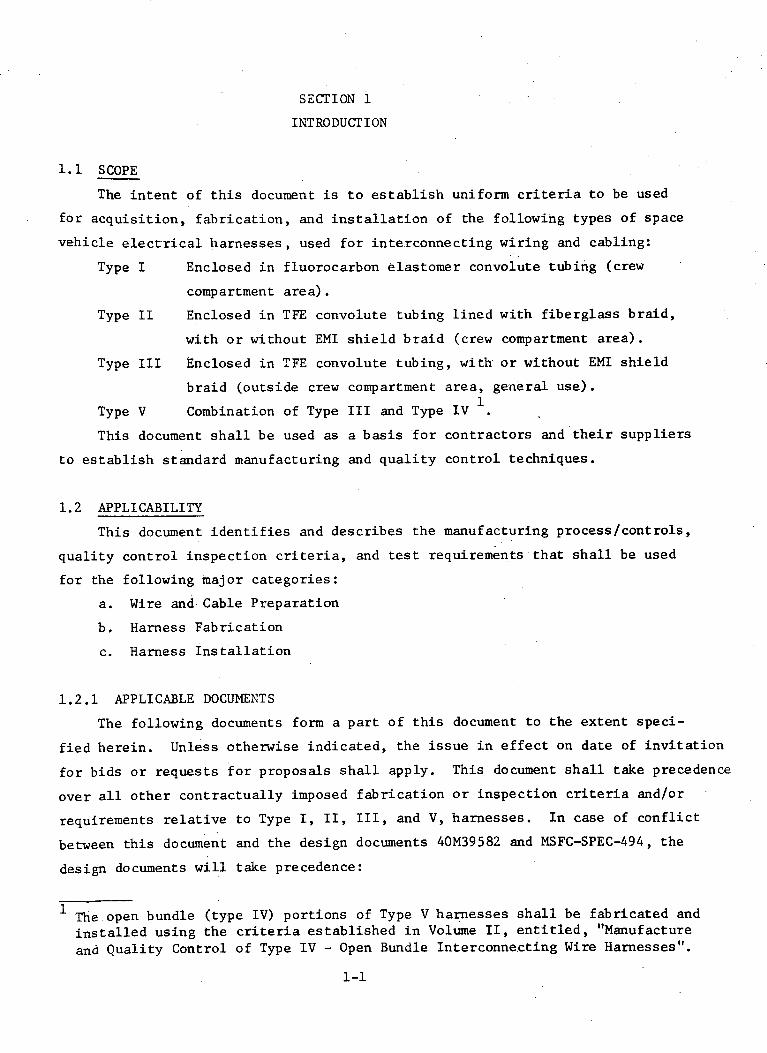
1.1 SCOPE
The intent of this document is to establish uniform criteria to be used
for acquisition, fabrication, and installation of the following types of space
vehicle electrical harnesses, used for interconnecting wiring and cabling:
Type I Enclosed in fluorocarbon elastomer convolute tubing (crew
compartment area).
Type II Enclosed in TFE convolute tubing lined with fiberglass braid,
with or without EMI shield braid (crew compartment area).
Type III Enclosed in TFE convolute tubing, with or without EMI shield
braid (outside crew compartment area, general use).
Type V Combination of Type III and Type IV .
This document shall be used as a basis for contractors and their suppliers
to establish standard manufacturing and quality control techniques.
1.2 APPLICABILITY
This document identifies and describes the manufacturing process/controls,
quality control inspection criteria, and test requirements that shall be used
for the following major categories:
a. Wire and Cable Preparation
b. Harness Fabrication
c. Harness Installation
1.2.1 APPLICABLE DOCUMENTS
The following documents form a part of this document to the extent speci-
fied herein. Unless otherwise indicated, the issue in effect on date of invitation
for bids or requests for proposals shall apply. This document shall take precedence
over all other contractually imposed fabrication or inspection criteria and/or
requirements relative to Type I, II, III, and V, harnesses. In case of conflict
between this document and the design documents 40M39582 and MSFC-SPEC-494, the
design documents will take precedence:
1The open bundle (type IV) portions of Type V harnesses shall be fabricated andinstalled using the criteria established in Volume II, entitled, "Manufactureand Quality Control of Type IV - Open Bundle Interconnecting Wire Harnesses".
1-1

1.2.1 APPLICABLE DOCUMENTS (Continued)
40M39582 - Harness Electrical Design Standard
40M51284 - Tubing, Convolute, Specification for
MSFC-SPEC-494 - Installation of Harness Assembly (Electrical
Wiring), Space Vehicle, General Specification for
NASA-NHB-5300.4 (1B) - Quality Program Requirements
NASA-NHB-5300.4 (3A) - Requirements for Soldered Electrical
Connections.
MIL-STD-202 - Test Methods for Electronic and Electrical
Component Parts
MSC/MSFC-JD-001 - Crimping of Electrical Connections
1.2.2 APPLICABLE STANDARDS AND SPECIFICATIONS
The reference to applicable standards and specifications in the body of
this document refers to NASA approved contractor's detailed procedures.
Contractors may utilize these procedures if they meet or exceed the require-
ments set forth in this document. In case of conflict between this document
and the contractor's procedures, this document shall take precedence.
Typical NASA documents which detail these procedures are listed below:
NASA SP5002 - Soldering Electrical Connections
SR-QUAL-65-25 - Manufacturing and Quality Control Requirements
for Space Systems Electrical Harnesses
SR-QUAL-67-20 - Apollo Saturn Stage Electrical Cable Installation
Inspection Criteria
S&E-QUAL-70-4 - Crimping Electrical Connections
1.3 DEFINITIONS
For the purpose of this document, the following definitions shall apply.
1.3.1 TYPE I - Harness enclosed in fluorocarbon elastomer convolute tubing -
shall consist of a group of wires, cables, or a combination of both, bundled
together, and enclosed in a fluorocarbon elastomer convolute tubing. The
harness may have only two termination points.
1.3.2 TYPE II - Harness enclosed in TFE convolute tubing lined with fiberglass
braid - shall consist of a group of wires, cables, or a combination of both,
bundled together, and sheathed with a fiberglass braid, and enclosed in TFE
1-2

1.3.2 TYPE II (continued)
convolute tubing. The harness may, or may not, be enclosed in an overall
electrostatic shield braid over the fiberglass braid, and may have two or
more termination points.
1.3.3 TYPE III - Harness enclosed in TFE convolute tubing shall consist of
a group of wires, cables, or a combination of both, bundled together, and
enclosed in TFE convolute tubing. The wires and/or cables may, or may not,
be enclosed in an overall electrostatic shield braid. The harness may have
two or more termination points.
1.3.4 TYPE V - Combination of Type III and Type IV - shall consist of a
group of wires, cables, or a combination of both, bundled together, with a
portion(s) of the harness enclosed in convolute tubing may, or may not, be
enclosed in an overall electrostatic shield braid. The harness may have two
or more termination points.
1.3.5 WIRE - A single insulated conductor of solid or stranded construction
without a shield, designed to carry current in an electrical circuit.
1.3.6 CABLE - Two or more insulated conductors, solid or stranded, contained
in a common sheath, shield, or jacket; or two or more insulated wires twisted
or molded together with or without a common cover; or one or more insulated
conductor with a metallic covering shield or outer conductor (insulated or
uninsulated).
1.3.7 SHIELDING - The braided metal sleeving surrounding an insulated con-
ductor, a group of wires, cables, or a combination of both, that provides
protection against electrostatic interference.
1.3.8 CONVOLUTE TUBING - The nonmetallic convoluted tubing surrounding an
insulated conductor, a group of wires, cables, or a combination of both, that
provides protection against abrasion, or high temperatures.
1-3
SECTION 2
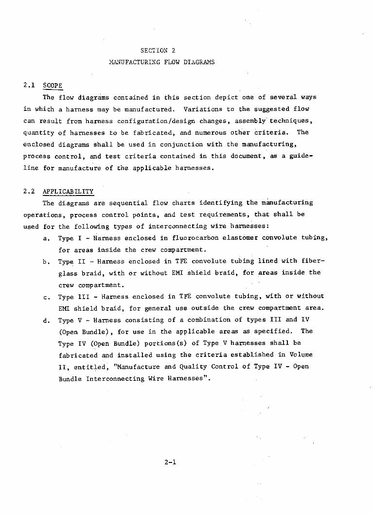
MANUFACTURING FLOW DIAGRAMS
2.1 SCOPE
The flow diagrams contained in this section depict one of several ways
in which a harness may be manufactured. Variations to the suggested flow
can result from harness configuration/design changes, assembly techniques,
quantity of harnesses to be fabricated, and numerous other criteria. The
enclosed diagrams shall be used in conjunction with the manufacturing,
process control, and test criteria contained in this document, as a guide-
line for manufacture of the applicable harnesses.
2.2 APPLICABILITY
The diagrams are sequential flow charts identifying the manufacturing
operations, process control points, and test requirements, that shall be
used for the following types of interconnecting wire harnesses:
a. Type I - Harness enclosed in fluorocarbon elastomer convolute tubing,
for areas inside the crew compartment.
b. Type II - Harness enclosed in TFE convolute tubing lined with fiber-
glass braid, with or without EMI shield braid, for areas inside the
crew compartment.
c. Type III - Harness enclosed in TFE convolute tubing, with or without
EMI shield braid, for general use outside the crew compartment area.
d. Type V - Harness consisting of a combination of types III and IV
(Open Bundle), for use in the applicable areas as specified. The
Type IV (Open Bundle) portions(s) of Type V harnesses shall be
fabricated and installed using the criteria established in Volume
II, entitled, "Manufacture and Quality Control of Type IV - Open
Bundle Interconnecting Wire Harnesses".
2-1

O; TOS THIS FLOW CHART DEPICTS ONE Or SEVERAL WAYSIN WmICH A HARNESS ENCLOSED IN FLUORCARBONZLASTOME CONVOLATE TUBING MAY BE MANUrAC.T TuRr, VARIATIONI o THE rLOW CAN RESULT
,i| rFROM HAIRNE CONIOURATION/DrESIGN CIANES,.*AUYBLY TErJoDGUrJ, AND QUANTITY or
HA N _,,,, .TOREI F.AIIrICATED.. _.
. . . . .~~I
MATERIAL VERIFICATIONINSPECT/VERIFY TMPRR
-1. VERIFY COMPLIANCE TO IRE CABLE WIREUR W(/CA SECURINGURTINW OS~I~- RECEIVlNG PROCUREMENT REQUIRE- CUTTING WLRE/CABLE A_ -L CONFIGURATION_ OFHARNESS
MENTS (INITIAL} NTCATION LAYOUT ]2. CLEANLINESS ]CONFIGURATIONZ. MATE R I A L P R OP E R L Y 3 PROTECTION
IDENTIIEDIDENTLFIEDJ~~~~~~ 'SECTION 6
SECTION 6 PARAGRAPHS 63 SIS SECTION 4 SECTION S SECTION 6 SECTION 76,3. 1, & 6.4
I RELATED CONVOLUTE TUBING
.
SECTION 9PARAGRAPH 9.9. 2 & 9. 10.4
(AS APPLICABLE)
RELATED ADAPTEIAND CONNBCTOR
IBOOTS I I F __
INSPECT/VERIFY
CONVOLUSE \_ 1. APPLICATIONTUBIN OFP TUBING
PPLICT ON Z. LENGTHS. SIZE4/ DA M A GE
SECTION ISSECTION is PAtAGRAPHS IS. 4. 4
ELATED FERRULES,.EEVES. RINGS,NID MATERIALS
,i
SECTION 9
AND CON-NECTOR BOOTAPPLICATION
INSTALL BOOTIN.
RETRACTED
SECTION 15PARAGRAPH 15. 4. 1
SECTION ISPARAGRAPHS IS.4.4
m CUTTING1TrtPPING (FINAL)
SECTION B SECTION 4
Y I RLATED PMIN,LLED CONTACTS, AND
I MATERIALSOF
RELATED CONNECTO AND MATER~
IASSEIMLY
SECTION II
PARAGRAPHS 11. 37 L 11.4.4(AS APPLICABLE)
NON-POTTED CONNECTORS
INSP CT/yERIFYIOR POTTED CONNECTORS)
|; CLEANLINESS (NO LOOSEWIRE STRANDS, SOLDER,LUBRICANTS, OR OTHERFOREIGN MATERIAL)
I UAMSA LIGNETD OR BNT .
INSPECT/VERIFY
1. CRIMPING rLI cAILE 1. PROPER USE T ATN
OF TOOLS
SECTION 10PARAGRAPHS 10.3.4 & 10.4.4 SECTION 10
(AS APPLICABLE)
J OCONTINUED
I1/~ ./-PaE-TE~tVE~l I/ \.1 | INSPECT/VERtrYII RETEST/VERLIP / I 1. AMI BUBBLES
CONTINUITY AND NSULA- POTTING L. CLANLINESSTION RESSTANCE TST X1 ~'"'S""'T"*lA "/ 3. SURrACE I (OPTIONAL) \ / I BLEMISHE I
I ' _ SECTION: 22 - 14. HARDNES IIET _SECTSON 12
'I 52:~SECTION 12 PARAGRAPH 12.6 1SECT tIO A-N l2 I
I PARAGRAPH 12 Z I
t- - - POTTED CONNECTORS J
FLOWCHART 2-1 (TYPE I-HARNESS ENCLOSED IN FLUOROCARBON ELASTOMER CONVOLUTE TUBING)
2-2
SYMBOL IDENTIFICATION
' O'Iv'Q MANUrACj R.Nc a(SIGNIfiCANT OPnRATI ON)
I mSPECTION OR° -SGNlrICANT CONTROL PONT + Pa
ILPECT/VERI.,
-. CONDUCTOR AND.SHIELD DAMAGE
,. APPEARANCE ' 3. INSULATION DAMAGE4. INSULATION RMOVAL
. DIMENSIONSi CRIMPING
INSPECT/VERIFYi. ADAPTERS INSTAI
PROPERLY. ADAPTERS rFREE
DAMAGE3. BOOTS FREE OF
DAMAGE4. PROPER USE OF
TOOLS -IINS'IECTY/VIRL'Y
1. GROMMET fREE OrDAMAGE
1. HARNESS DIASETZR/DRESSING
3. WIRE BEND RADIUS4. PINS AND SOCKETS
INSERTED ANDLOCKED
rH- - - - - - - - - - - - - - - - - - --I I
i.
SHACN SS
SECTION 16SECTION 1
o
~~~~~~~~~~~~~~~~~~~~~~~~~~~~~~~~~~~~~~I II
I.
J&. AU&A&4CiNJ&LP oft Burr .I PINS3. COUPLINC RINC ROTATX~l

I.. CONTINUITY AND INSULA.' TION RESISTANCE TEST2. DIELECTRIC WITHSTAND-
NG VOLTAGE TEST /
SECTION 2Z
SECTION 18 SECTION 17
l"CS /VS am . INSPECT/VER r Iy1. SZND "IUfI r /VER ty. 1. PROPER MATING
CXAIL a . . . . . . . , . Z. APPEARANCE POST INSTALLATION.CRAM.~O ' .tIN...............LA- 3raft. DAMAGE ' IVERIFICATION3T. PEII~TA CNCE F STION STANC TI ST 4. CORRECIDENON 23
.~~~~~~~~~~~~~~~~~~~~~~~~~~~~~~~~~~~~~~~~~~~~~~~~~~~~~~~~~~~~ ,4, PiOPZel IDENT SECTION ZZ IFIGATION
.PARACRAPH IP.( SECTION 21'PARAGRAPH 19.6 SECTION 21 PARAGRAPH 21.6SECTION 20PARAGRAPH 20.S
TO FINAL SYSTEMSCOMPATABILITY TEST
FLOWCHART 2-1 CONTINUED (TYPE L-HARNESS ENCLOSED IN FLUOROCARBON ELASTOMER CONVOLUTi TUBIN'G)
NOTE: THIS FLOW CHART DEPICTS ONE OF SEVERAL WAYSIN WHICH A HARNESS ENdLOSED IN TFE CONVOLUTETUBING, LINED WITH EMI SHIELD AND FIBERGLAUBRAID, MAY BE MANUFACTURED. VARIATIONS TOTHE FLOW CAN RESULT FROM HARNESS CONFI CGUA.TION/DESIGN CHANGES, ASSEMBLY TECHNIQUES,AND QUANTITY OF HARNESSES TO BE FABRICATED,
MATERIAL VERIFI CATION
~TEMPORARY \~INSPECT/VERIFYRECEIVING 1. VERIFY COMPLIANCE TO WRECABL WIRE/CABLE WIRECABL 1. CONFIGURATION
PROCUREMENT REQUIREMENTS CUSIG NTIFICAT10N/ LAYOUT , 2. CLEANLINESSZ. MATERIAL PROPERLY T / 3PROTECTION
IDENTFIED \ / / \ / CTION ~~~~~~~~~~~~~~~~~SECTION 3 SECTION 3 PARAGRAPHS ,., S... 1, L 6.4
SECTION 4 SECTION S SECTION 6
|RELATED FERRULES,SLEEVES, RINGS,AND MAS TRIALS \EMPORARY
WIN E/CABLE WIRECABLE SECURINGSS P~t~a CUTTING Or HARNESS
STRIPPING (FINAL) IGURATO
SECTION 8 SECTION 4 SECTION 7
I/ \SECTION I3PARAGRAPH 13, S .1
SECTION 13
L _ _EMI SHIELD BRAID
SECTION 15
INSPECT/VERTIFY
1. CRIMPINGZ, PROPER USE
OF TOOLS
SECTION 10PARAGRAPHS 10. 3.4 I 10.4.4
(AS APPLICABLE)
LATED CONNEC- RS AND MATERIAL|
ASSEMBLY
SECTDIN 11
Pi
TEMPORARY IHARNESS CONTINUED
SCTICATON 1
ISECTION 16SCv rIO 1
ARAGRAPHS 11.3.1 & 11. 4.4( AS APPLICABLE)
FLOW CHART 2-2 (TYPE I I-HARNESS ENCLOSED I1N TFE CONVOLUTE TUBING, LINEDWITH FIBERGLASS BRAID, WITH OR WITHOUT EMI SHIELD BRAID)
2-4
SYMBOL IDENTIFICATION
= FUNCTSOM&L SIIIQ MANUFACTURING(SIGNIFICANT OPERATION) /\ STOCK
INSPECTION- BR· (SIGNIFICANT CONTROL POINT) +
INSPECT/VERIFY
1. GROMMET FREE OFDAMAGE
2. HARNESS DIAMETER/DRESSING
3. WIRE BEND RADIUS4. PINS AND SOCKETS
INSERTED ANDLOCKED
- r_ __
I
I
i
C TION 11s
" 1 I---
INSPECT/VERIFY(OR POTTED CONNECTORS) N
1. CLEANLINESS (NO LOOSE ( PRE.TEST/VERFY I. ARBUBLE
. MISALINED ORBEN (OPTIONAL) I BLEMISHES {PINS RDNESPINS| SECTION ZIZI3. COUPLING RING ROTATESN
SECTION 12 SECTION 12 PARAGRAPH 12. 6PAR . APH IZ. L
L _ _ _ _~ _ _ _ _ _POTTED CONNECTORS j
TEST/VZRLFY
1. CONTINUITY ANDINSUL_ INSPECT/VERFY HARNESS CONECTORTION RESISTANCE TEST 4- 1. ADAPTER APPLICATION -I DENTlICATIONk- ADAPTER
\2. DIELECTRIC WITHSTAND- / 2. HARNESS IDENT . TERMINATIONINGO VOLTAGE TEST I 13 CONNECTOR IDENT
SECSION t2 SECTION I5PARAGRAPH 15 5..
SECTION 16 SECTION 16 SECTION ISPARAGRAPH 16. 10
1. BEND RADII2. PROTECTION FRO -"
CHAFINGS. PROPER CLAMPINO4. PROPER IDENT
SECTION 19SECTION II SECTION 19 SECTION 20 PARAGRAPH 19.6
SECTION 20PARAGRAPH 20. 5
INSPECT/VERIFY
I. PROPER MATING TesT/VZRPOST INSTALLATION 1. APPEARANCE CONNECTOR[VERIFICATION r. DAMAGE MATING CONTINUITY AND UUL- .
SECTION 23 4. CORRECT IDENT. RESISTANCE TESTIFICATION SECTION aZ
SECTION Z1PARAGRAPH 21.6 SECTION 21
tA ~TO FINAL SYSTEMSV COMPATABILITY TEST
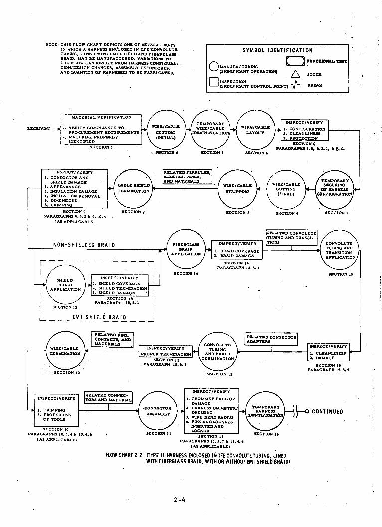
FLOW CHART 2-2 CONTINUED (TYPE II-HARNESS ENCLOSED IN TFECONVOLUTETUBING, LINEDWITH FIBERGLASS BRAID, WITH OR WITHOUT EMI SHIELD BRAID)
2-5
17
NON-POTTED CONNECTORS

NOTE: THIS FLOW CHART DEPICTS ONE OF SEVERAL'WAYSIN WHICH A HARNESS ENCLOSED IN TFE CONVOLUTETUBING AND EMI SHIELD BRAID MAY BE MANUFAC-TURED. VARIATIONS TO THE FLOW CAN RESULTFROM HARNESS CONFIGURATION/DESIGN CHANGES,ASSEMBLY TECHNIQUES. AND QUANTITY OF HAR-NESSES TO BE FABRICATED.
SYMBOL I'DENTIFICATION -
= FUNCTIONAL TESTIO MANUFACTURING NCTONA(SIGNIFICANT OPERATION) A STOCK
INSPECTION D{SIGNIFICA ONTROL POINT) BREAKCONTROL POINT) ~- i__ _
RELATED CONVOLUTETUBING AND TRANSI-TIONS S 7,NON-SHIELDED BRAID ONSCONVOLUTERIFY
TUBING AND 1 Lc'%i~ ~ ~ I TAlTO 'l°CLSANLMESSr'--TRANSITION
APPLICATIONH / ~- - -~- - - -- - - - _\~/ SECTION 15J ~~~I / PARAGRAPHI I.S. 5.
|J~~~~~ ~ ~~~ / \ I ~SECTION 15INSPECT/VERIFY
BRAID * 1. SHIELD COVERAGE APPLICATION 2. SH LD TERMINATION
3. SHIELD DAMAGE
SECTION 13PARAGRAPH 13. 5. I
SECTION 13
L - - -EMI SHIELD BRAID __ I
INSPECT/VERIFY
PROPER TERMINATION
SECTION 15PARAGRAPH 15. 5.5
RELATED CONNEC-INSPECT/VERIFY ITORS AND MATERIAL[
1. CRIMPING2. APPLICATION I
. OF SLEEVING3. PROPER USE
OF TOOLS
SECTION 10PARAGRAPHS 10. 3.4 10.4.4
(AS APPLICABLE)
CONNECTOR
SECTION IISECTION 11
PARAGRAPHS 11.3.7 & 11.4.4(AS APPLICABLE)
TEMPORARYHARNESSCONTINUED
SETIFICATON T
ISECTION 16.
FLOW CHART 2-3 (TYPE III-HARNESS ENCLOSED IN TFE CONVOLUTETUBING, WITH OR WITHOUT EMI SHIELD BRAID)
2-6
CNOLUTETUBING TER
MINATION AND,WHEN APPLICABLE, SHIELD
RAID TERMINATION
SECTION 15
INSPECT/VERIFY
1. CROMMET FREE OFDAMAGE
2. HARNESS DIAMETER/DRESSING
3. WIRE BEND RADIUS4. PINS AND SOCKETS
INSERTED ANDLOCKED
RELATED CO.tNE ,ORADAPTERS
I RELATED PINS,I CONTACTS. AND .LATERIALS l
Ls E/CAELII ,
SECRMINTION l
SECTION 10
o
erv,^.1 a

NON-POTTED CONNECTORS
r - - - -- --- - - -- -INSPECT/VERIly
(rOR POTTED CONNECTORS) INSPECT/VERIY
I1 CLEANLINESS (NO LOOSE PRE-TEST/VERFY 1. A BUBBLEWIRE STRANDS. SOLDER. CONTINUITY AND INSULA. POTTIN CLEANLINESSLUnRICANTS. OR OTHER T CON RESISTANCE TESST ENAP. . SURFPACEFOREIGN MATERIAL) OPTIONAL) LEMISHEl
:1. MISALIGNED OR ENT - ROPTIONAL \ NESSPINS SECTION Z2ECTiON 12
I . COUPLING RING ROTATES SECTION PAGRAPH 12.6SECTION I' PARAGRAPH 12.6
SECTION 12PARAGRAPH 12. Z
POTTED CONNECTORS j
TESTTVERIFYI
- CONTINUITY AND INSULA INSPECT/VERFY RNESS CONNECTOR
TION RESiSTANCE TEST ' 1. ADAPTER APPLICATIONII DENTWICATIONIQ- ADAPTER~,. DIELECTRIC WSTHSTAND- . HARNESS IDENT i ' \TERMINATION.NG VOLTAG^E TEST / 3 . CONNECTCR IDENT
SECTION s15SECTION 2 PARAGRAPH IS. S. S
SECTION 16 SECTION 16 SECTION ISPARAGRAPH 16. 10
INSPECT/VERIY.
1. BEND RADII2. PROTECTION raom
CHAFINGS. PROPER CLAMPING4. PROPER IDENT
SECTION 19PARAGRAPH 19.6
SECTION 20PARAGRAPH 20. 5
INSPECT/VERIFY
I. PROPER MATING. APPEARANCE
3. DAMAGE4. CORRECT IDENT.
IFICATION
SECTION 21PARAGRAPH 21.6
2z
SECTION 21
TO FINAL SYSTEMSCOMPATABILITY TEST
FLOW CHART 2-3 CONTINUED (TYPE III-HARNESS ENCLOSED IN TFE CONVOLUTETUBING, WITH OR WITHOUT EMI SHIELD BRAID)
2-7
SECTION 17

NOTE:. THIS FLOW CHART DEPICTS ONE OF SEVERAL WAYSIN WHICH'A COMBINATION TYPE III AND TYPE IVHARNIESS MAY BE MANUFACTURED. VARIATIONS TOTHE THE FLOWCAN RESULT FROM HARNESS CON-FIGURATION/DIESIGN CHANGES, ASSEMBLY TECH-NIQUES, AND QUANTITY OF HARNESSES TO BEFABRICATED. -
MATERIAL VERIFICATION
TEMPORARY\ / \I INSPECT/VERwY1. VERIFY COMPLIANCE TO WIRE/CABLE WRECABLE WIRE/CABLE 1. CONFIGURATION
PROCUREMENT REQUIREMENTS CUTTING IDENTIFICATION LAYOUT . CLEANLINESSZ. MATERIAL PROPERLY \INITIAL) / PROTECTION
IDENTIFIED \ / \ / SECTION 6SECTIONS PARAGRAPHS3 ., 6.. 1. 6&.4
SECTION 4 SECTION S SECTION 6
SECTION 4 SECTION 7SECTION 8
SECTION 15
1 PARAGRAPH 13.5.1SECTION 13
L_ - EMI SHIELD BRAID I
TUBING TER- IINSPECT/VZRUrY INATION AND
HNAPPLICA-PROPER TERMINATION. BLE. SHIELD
SECTION Is \BRAID TERM- .PARAGRAPH 15.5.5 \ NATION
SECTION 15
INSPECT/VERIFYRELATED CONNEC.TORS AND MATERIAL 1. GROMMET FREE OF
DAMAGE
CONECTOR Z. HARNESS DIAMETER/ TEMRARYSSEBLY DRESSING NSS CONTINUED3. WIRE BEND RADIUS I4. PINS AND SOCKETS
INSERTEDAND0.4 LOCKED
10.4,4 SECSECTION 11 SECTION 16SECTION I1
PARAGRAPHS 11. 3.7 & 11.4.4 (AS APPLICABLE)
FLOW CHART 2-4 (TYPE V-COMBINATION OF OPEN BUNDLE HARNESS (TYPE IV) AND HARNESS ENCLOSEDIN TFE CONVOLUTE TUBING (TYPE III), WITH ORWITHOUT EMI SHIELD BRAID)
2-8
SYMBOL IDENTIFICATION
,,ANUFACTURING,,(SIGN!FICANT OPERATION) A n SCo
INSPECTION TROL T (SICNLYICANT CONTROL POINT) + B I
RECEIVING -_
.,I
IRELATED CONNICTORADAPTERS
I
NON-POTTED CONNECTORS
INSPECT/VERIFYFO POTTED CONNECTORS '
4 CLEANLINESS (NO LOOSE/ INSPECT/VERIFY
LURICANTS. A.N OTER CONTINUITY AND INSULA.I . CLEANLINESSL C OR TION RESISTANCE TEST ENCAPSULAFOaEIGN MATERIAL)2. MISALIGNED OR BENT (OPTIONAL) BLEMISHES
PINS SECTON 22HARDNESS3. COUPLING RING ROTATES SECTION N 12
SECTION IZ srCTION .Z PARAGRAPH 32.6PARAGRAPH 12.2
L _ __ _ _ ___".4"ECPOTTED CONNECTORS j_ _ _ _ _ _ _ _ _ _ _ _ _ _ _ _"
TEST/VERIFY
1.. CONTINUITY AND INSULA. -TION RESISTANCE TEST
2. DIELECTRIC WITHSTAND-l.ING VOLTAGE TEST
SECTION 22
INSPECT/VERIFY1.HA RNESs \ CONNE~
1. ADAPTER APPLICATION DENTSICATIO ADAPTER2. HARNESS IDENT TERMINATION3. CONNECTOR IDENT
SECTION ISPARAGRAPH 15. 5. 5
SECTION 16 SECTION 16 SECTION ISPARAGRAPH 16. IC
1. BEND RADII2. PROTECTION FROM
CHAFING3. PROPER CLAMPING4. PROPER IDENT
SECTION IS SECTION 19
SECTION ZS
SECTION 21PARAGRAPH 21.6
SECTION 19SECTION 20 PARAGRAPH 19. 6
SECTION 20PARAGRAPH 20. 5
22
SECTION 21
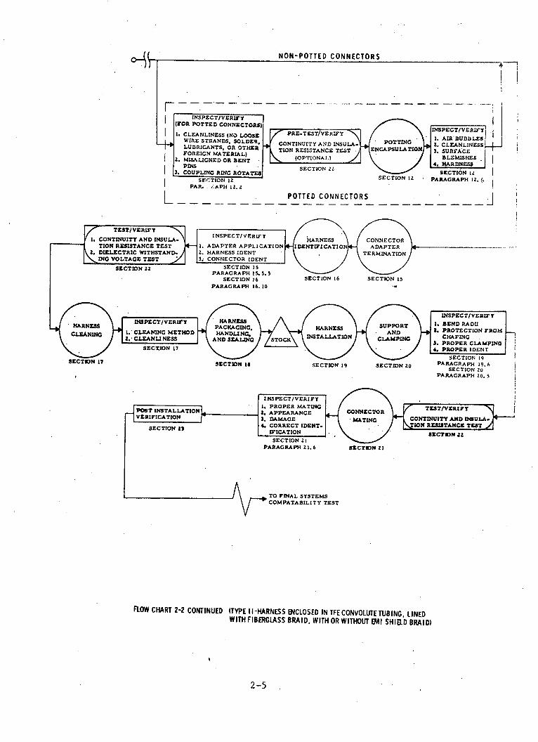
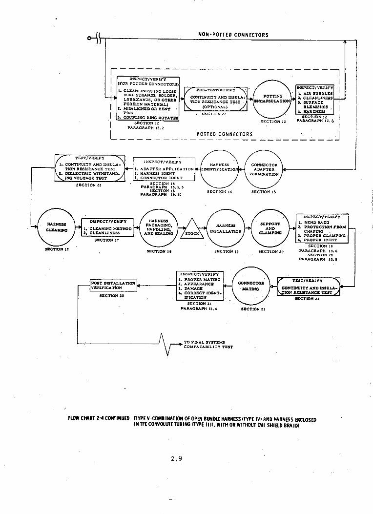
.FLOW CHART 2-4 CONTINUED (TYPE V-COMB INATION OF OPEN BUNDLE HARNESS (TYPE IV) AND HARNESS ENCLOSEDIN TFE CONVOLUTE TUBING (TYPE III), WITH OR WITHOUT EMI SHIELD BRAID)
2.9
N- \ I //
SECTION 17
(I

SECTION 3
RECEIVING INSPECTION
3.1 GENERAL
This section defines the minimum requirements for inspection verifica-
tion of electrical materials acceptance, prior to issuance for manufacturing
operations.
3.2 SCOPE
Electrical materials are those articles employed in fabrication and
installation of interconnecting electrical wire/cable harnesses and consist
of, but are not limited to, convolute tubing and its associated fittings,
adapters and transitions, hookup wire and cable, coaxial cables, insulation
sleeving, conductor and shield terminations (ferrules, sleeves, rings),
connectors, clamps, tie-cord material, potting materials, solder, fluxes, and
associated materials.
3.3 PURPOSE
The purpose of acceptance inspection is to assure that suppliers of
production materials have adequately performed the required inspections and
tests necessary to assure a quality product which meets procurement specifica-
tion requirements. Acceptance inspection tests shall be conducted on a random
sample, selected from each lot, batch, or group of materials submitted for
acceptance at one time. Acceptance inspection tests shall not alleviate the
supplier of his responsibility for performing all inspection and test require-
ments as specified in the procurement documents.
3.4 REQUIREMENTS
The materials and associated articles procured for fabrication and
installation of interconnecting space vehicle electrical harnesses shall meet
the following requirements and any additional requirements specified by the
procurement documentation.
3.4.1 CERTIFICATION OF CONFORMANCE REPORT
When specified, certification prescribed by the procurement specification
shall be reviewed for conformance to requirements.
3-1

3.4.2 SAMPLING FOR ACCEPTANCE
Sampling shall be defined as a length, group, or individual units
randomly selected from a lot, batch, or group submitted for acceptance
inspection and test at one time. Sampling shall be planned in accordance
with NHB 5300.4 (1B), paragraph 1200, which provides direction for establish-
ing and maintaining sampling plans.
3.4.3 EXAMINATION OF MATERIALS
Each inspection lot and type of material submitted for acceptance shall
be given a careful visual and dimensional examination to determine compliance
with the applicable procurement specification requirements. Dimensional
inspection shall be made using micrometers, calipers, microscopes, or
equivalent types of precision measuring instruments to determine product
dimensional compliance. Materials shall be subjected to those tests as
required to assure complete compliance to procurement specification acceptance
and/or to validate conformance to paragraph 3.4.1. Examination of materials
shall be performed in facilities as directed in paragraph 3.4.4.
3.4.4 FACILITIES
Facilities utilized for materials inspection and testing shall, as a
minimum, satisfy the environmental and cleanliness levels directed by the
procurement specification for the materials to be processed. Environmental
and cleanliness controls shall be invoked to assure continued maintenance
of prescribed levels.
3.5 WIRE AND CABLE
Wire and cable shall be subjected to a visual inspection to assure
compliance with the detail procurement specification requirements (i.e.,
identification, contamination, evidence of damage, and general workmanship).
Samples, as defined in paragraph 3.4.2., shall be subjected to the following
inspection and tests, as prescribed in the detail procurement specification.
3.5.1 VISUAL EXAMINATION
Visually inspect wire and cable to assure compliance to the detail design
requirements. As a minimum, the following condition shall be inspected for:
a. Outer insulation cracking or flaking
3-2

3.5.1 VISUAL EXAMINATION (Continued)
b. Damaged wire insulation
c. Burned or charred insulation
d. Incorrect insulation material
e. Nicks, rings, scrapes, or scratches on outer conductor
strands, through plating
f. Insufficient number of strands
g. Tarnished or corroded wire
h. Untwisted lay of strands
i. Broken and/or loose shield strands
j. Incorrect type or class insulation or sheath
3.5.2 ELECTRICAL TESTS
As a minimum for acceptance, wire and cable shall be subjected to the
following electrical tests in compliance with the detail design procurement
specification:
a. Dielectric withstanding voltage test
b. Insulation resistance test
c. Conductor D.C. resistance test
3.6 ELECTRICAL CONNECTORS
Each connector shall be subjected to a comprehensive visual examination
for compliance with the detail procurement requirements, correct identification,
and to assure that the connectors are free of contamination and/or damage.
Connectors shall be packaged to provide protection from mishandling, contamina-
tion, and accelerated aging during storage. As a minimum, the following
unsatisfactory conditions shall be inspected for:
a. Imperfections in grommets extending into the chamfer area.
b. Obvious cuts or gouges which may reduce the sealing ability of
the grommet.
c. Obvious splits and misaligned grommets.
d. Mold flash extending into pin (contact) hole.
e. Missing or improper o-rings.
f. Tarnished or corroded contacts.
g. Nicks, rings, scrapes, or scratches.
h. Cracking or flaking of plating
i. Wrong type plating
3-3

3.6 ELECTRICAL CONNECTORS (Continued)
j. Visible dirt, grease, or other foreign materials.
k. Correct number and size of pins/sockets.
3.7 POTTING MATERIALS
Potting materials shall be randomly sampled and tested to assure compliance
with the detail procurement requirements. The following criteria shall be
inspected as a minimum:
a. Hardness
b. Accelerated pot life
c. Adhesion
d. Shelf life identification
e. Storage requirements
f. Electrical requirements (when applicable)
g. Tensile strength
3.8 INSULATION SLEEVING
Insulation sleeving materials shall be sample inspected to assure con-
formance to the detail procurement specification. The following tests shall
be conducted as a minimum for acceptance:
a. Dimensional compliance, as received and after heat application.
b. Longitudinal shrinkage.
c. Dielectric withstanding voltage test.
d. Material identification
3.9 COAXIAL CABLE
Coaxial cable shall be subjected to those acceptance requirements as
noted in the detail procurement specification, and as a minimum, be subjected
to the following inspections and tests:
a. Dimensional compliance (i.e., dielectric and jacket thickness).
b. Shield braid coverage.
c. Attenuation and impedance.
d. Identification marking.
3.10 CONDUCTOR AND SHIELD TERMINATIONS
Each lot, batch, or group of conductor terminations (ferrules, sleeves,
rings, etc.) submitted for acceptance shall be randomly sampled and inspected
for the following criteria, as a minimum:
3-4

3.10 CONDUCTOR AND SHIELD TERMINATIONS
a. Dimensional Compliance
b. Tarnished or corroded contacts
c. Wrong type plating
d. Visible dirt, grease, or other foreign materials.
e. Cracking or flaking of plating.
f. Insulated ferrule damage.
3.11 SOLDER AND SOLDER FLUX
Each lot or batch of solder and/or flux shall be required to have a
certification of compliance and chemical analysis data submitted with each
receival. In addition, the following criteria shall be inspected as a
minimum:
a. Correct identification marking in accordance with the detail
procurement specification.
b. Each spool, box, or can, adequately marked with a batch or
lot number.
3.12 TIE-CORD MATERIALS
Each lot or batch of tie-cord submitted for acceptance shall be inspected
for correct identification to type and class of materials.
3.13 CONVOLUTE TUBING
Acceptance inspection tests shall consist of the following minimum tests:
a. Dimensional examination shall be made using micrometers, calipers, or
other equivalent types of measuring instruments to determine product
dimensional compliance. Tubing shall be measured for inner and outer
diameter, wall thickness and convolutions per inch.
:b. Physical properties testing shall be conducted to assure compliance
to ultimate elongation and specific gravity requirements as specified
in the detail procurement specification.
c. Convolute identification shall be such that each package of coiled
tubing shall be labeled to identify nomenclature, manufacturer's
part number, MSFC part number, quantity, purchase order number, and
lot code.
3-5

3.14 CONVOLUTE FITTINGS, ADAPTORS, AND TRANSITIONS
Each group of convolute fittings, adaptors, and transitions shall be
subjected to a detail physical examination to determine finish, construction,
and workmanship are free of defects. Dimensional configuration shall be
inspected on a randomly selected sample to assure compliance to the applicable
design requirements.
3.15 WIRE/CABLE SUPPORT CLAMPS
Wire and cable harness support clamps shall be submitted to a detail
physical examination to determine the following criteria, as a minimum:
a. Assure clamp dimensional configuration on a randomly selected sample.
b. Clamp material shall be free of gouges, cuts, or cracks.
c. Clamp material shall be of the type specified on the procurement
specification.
3.16 METALLIC BRAID WIRE/WOVEN BRAID WIRE
Wire used to form the electrostatic shield braid for Type II and Type III
harnesses shall conform to procurement specifications. As a minimum, each
spool of wire shall be inspected for correct material, dimensional compliance,
tarnish or corrosion, and adequate identification markings. When woven braid
wire is procured for direct application, it shall be inspected for compliance
to the preceding requirements and the requirements established in paragraph
13.4 of this document.
3.17 OTHER ASSOCIATE MATERIALS
The other materials used in the fabrication and installation of inter-
connecting wire/cable harnesses shall be subjected to the inspections and tests
necessary to assure conformance to the procurement specification requirements.
As a minimum, the following criteria shall be inspected for:
a. Adequate identification markings.
b. Dimension configuration, when applicable.
c. Workmanship.
d. Packaging and protection necessary to assure that no degradation
occurs during normal storage and handling.
3-6
SECTION 4
WIRE AND CABLE CUTTING
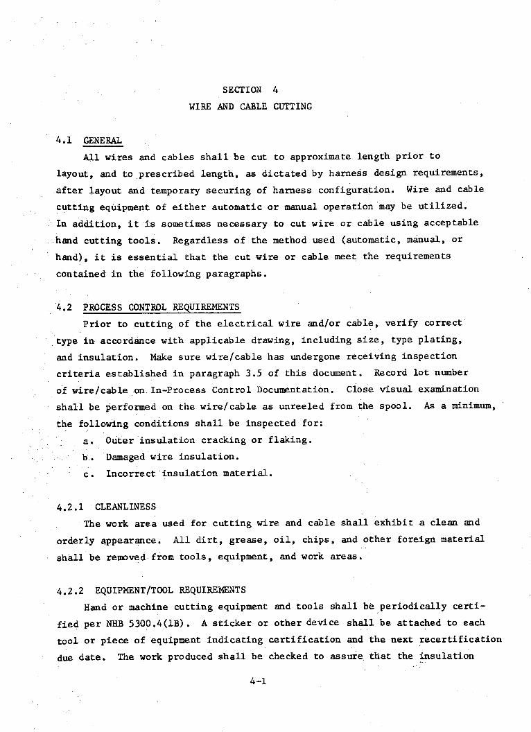
4.1 GENERAL
All wires and cables shall be cut to approximate length prior to
layout, and to prescribed length, as dictated by harness design requirements,
after layout and temporary securing of harness configuration. Wire and cable
cutting equipment of either automatic or manual operation may be utilized.
In addition, it is sometimes necessary to cut wire or cable using acceptable
.hand cutting tools. Regardless of the method used (automatic, manual, or
hand), it is essential that the cut wire or cable meet the requirements
contained in the following paragraphs.
4.2 PROCESS CONTROL REQUIREMENTS
Prior to cutting of the electrical wire and/or cable, verify correct
type in accordance with applicable drawing, including size, type plating,
and insulation. Make sure wire/cable has undergone receiving inspection
criteria established in paragraph 3.5 of this document. Record lot number
of wire/cable on In-Process Control Documentation. Close visual examination
shall be performed on the wire/cable as unreeled from the spool. As a minimum,
the following conditions shall be inspected for:
a. Outer insulation cracking or flaking.
b. Damaged wire insulation.
c. Incorrect insulation material.
4.2.1 CLEANLINESS
The work area used for cutting wire and cable shall exhibit a clean and
orderly appearance. All dirt, grease, oil, chips, and other foreign material
shall be removed from tools, equipment, and work areas.
4.2.2 EQUIPMENT/TOOL REQUIREMENTS
Hand or machine cutting equipment and tools shall be periodically certi-
fied per NHB 5300.4(1B). A sticker or other device shall be attached to each
tool or piece of equipment indicating certification and the next recertification
due date. The work produced shall be checked to assure that the insulation
4-1
4.2.2 EQUIPMENT/TOOL REQUIREMENTS (Continued)
has not been punctured, crushed, or otherwise damaged, and that the wire/
cable ends are cut square. Cutting efficiency shall be maintained by
replacing blades and calibrating when necessary.
4.3 WIRE/CABLE CUTTING OPERATIONS
The cutting operations shall be performed in such a manner that the
conductor strands, shielding (where applicable), and insulation are not
damaged adjacent to the cut end. Wire cutting equipment or tools shall not
cut, extrude, or otherwise damage adjacent insulation. Frayed insulation at
cut wire or cable ends is unacceptable, although a few fibrous threads of
fiber may be allowed to remain providing they do not interfere or represent
more than 10% of the total fiber stranding. Repetitive occurrences of
improper cutting of the wire/cable, or damage to the insulation, shall be
cause for maintenance and/or re-calibration of the equipment.
4-2

SECTION 5
TEMPORARY WIRE AND CABLE IDENTIFICATION
5.1 GENERAL
This section describes the procedures that shall be used for temporary
identification of wires and cables, when desired. Temporary wire and cable
identification is not a requirement established by this document, but is
included for the purpose of providing an assembly aid during the fabrication
and test cycles. If a temporary method of wire and cable identification is
utilized, care shall be exercised to ensure that the wires or cables are not
damaged by the identification procedure. In addition, precautions shall be
established to ensure that all temporary identification is removed prior to
application of harness protective covering, such as fiberglass braid, metallic
shield braid, or convolute tubing.
5.2 PROCESS CONTROL REQUIREMENTS
Prior to application of temporary wire and cable identification markers,
verify that all wire and cable outer insulation is free of surface damage
and/or contamination. Examine the wire and cable to be identified to assure
the correct type, class, or size, as specified on the applicable engineering
documentation. Verify the wire/cable has been cut to the requirements of
Section 4.
5.3 IDENTIFICATION METHODS
The combination of letters and numbers which constitute the wire/cable
identification code shall be in accordance with applicable manufacturing
standards. The identification marker shall be of the type that can be
slipped onto the wire/cable easily and will grip the wire/cable firmly, but
without causing damage (i.e., impressions, cuts, abrasion, etc.) to the
insulation. In addition, the marker(s) shall be of the type that can be
removed without cutting. It is suggested that identification markers of
the split sleeve, or tag type be used. Markers that rely on adhesive backing
to adhere to the wire/cable insulation shall not be attached to the harness,
5-1

5.3 IDENTIFICATION METHODS (Continued)
due to the possibility of adhesive residue remaining on the insulation after
removal of the markers. An alternate means of temporarily identifying wire
and cable is achieved by allowing each conductor an additional length of
wire adequate for the attachment of an identification marker. This markers
placed near the end of the conductor, is subsequently removed when the
excess conductor length, bearing the marker, is cut off.
5.4 LEGIBILITY
All identification characters on markers should be legible, permanent,
and colored to contrast with the surface on which the identification is placed.
In addition, the characters should be of sufficient size and color to provide
ease of identification.
5-2

SECTION 6
WIRE AND CABLE LAYOUT
6.1 GENERAL
This section establishes the fabrication criteria that pertains to
grouping, layout, and bundling of wires and/or cables into the desired
harness configuration, prior to application of the fiberglass braid, EMI
shield braid, or convolute tubing. Several other elements relative to
harness fabrication (securing, stripping, etc.) are covered elsewhere in
this document and should be referred to where applicable.
6.2 PROCESS CONTROL REQUIREMENTS
Prior to performing wire and cable layout operations, verify correct
type of wire/cable and that preceding cutting and stripping (if applicable)
operations have been properly performed. Make sure that wires/cables have
not been damaged and necessary process control verification has been performed.
In addition to the preceding process control requirements, the control and
handling precautions described in the following paragraphs shall be applied.
6.2.1 CONTROL AND CLEANLINESS OF MOCKUP AREAS
All mockup of electrical wiring shall be performed in a controlled
area. The general working area and benches shall be maintained in a clean
and orderly condition at all times. Only tools, fixtures, equipment, etc.,
which are required to perform the task shall be allowed in the area. Supply
cabinets or shelves used to store electrical wire, cable, components,
hardware, etc., shall be set aside from the immediate work area, and shall
be maintained in a clean and orderly condition to avoid contamination of
the electrical wiring and associated materials being assembled.
6.2.2 WIRE AND CABLE PROTECTION
All mockup boards or fixtures shall be inspected for sharp edges,
protrusions, and any other conditions that may damage wire and cable insula-
tion. All metallic guides and supports shall be covered with protective
sleeving or coating.
6-1

6.3 FABRICATION AND HANDLING PRECAUTIONS
The fabrication and handling of wires, cables, and harness assemblies
requires reasonable care to prevent damage and to assure cleanliness. In
addition to the handling and packaging procedures described in Section 18,
the following precautions shall be observed:
a. Wires, wire harness assemblies, and cables shall be fully supported
at all times. They shall not be allowed to hang over the edges of
work surfaces or to lay on protrusions that may cause damage to
conductors or insulation. In no instance will they be placed on
a surface, such as a floor, where they may be stepped on or damaged
by vehicular traffic. Tools or other foreign objects shall not
be layed on wire, wire harness assemblies, or cables during fabrica-
tion or stowage.
b. During handling, care shall be exercised to prevent wires, wire
harness assemblies, and cables from being dragged over any surface.
They shall be fully supported and lifted when moved.
c. Removal of temporary ties may be accomplished by the use of
diagonal cutters or "nipper-type" scissors. The cutting instrument
shall not be inserted between wires to facilitate cutting. Spot
ties may be easily removed by cutting off the finish knot.
6.3.1 CLEANLINESS PRECAUTIONS
Incomplete wires, cables, -and harness assemblies not in work (on benches
or jig boards) shall be completely covered with polyethylene film or equiva-
lent that will not degrade the intent of the completed harness. Work areas
shall be clean at all times. Wire cuttings, pieces of insulation or tying
material, and foreign material shall be cleared from the area as they occur.
Only tools in use shall be allowed on the working surfaces of benches and
jig boards.
6.4 LAYOUT
To facilitate installation and maintenance, route wires/cables in an
orderly fashion with individual wires and cables in a bundle generally parallel.
Avoid crossovers, snarles, tangles, or kinks. Refer to Figure 1, for typical
wire/cable layup. When laying out electrical wires and cables, caution shall
be exercised to avoid abrasion, cutting, or piercing of the insulation by
contact with rough surfaces, or sharp edges.
6-2

6.5 TWISTED LAY OF WIRE/CABLE BUNDLES
Wires and/or cables that are to be contained within convolute tubing
shall be grouped and bundled together in a twisted lay pattern as illustrated
in Figure 2, and as described in the following paragraphs.
6.5.1 TWISTED LAY PROCEDURE
When twisting is specified, it shall begin as close to the termination
as practical without causing undue stress on the connector adapter, support,
or branch point (preferrably within six inches). The length of the twisted
lay shall be 8 to 16 times the outer diameter (OD) of the harness (see
Figure 2), with each branch breakout being twisted at least one and a half
turns over its length, or it shall not be twisted. Shield termination wires
need not be twisted with the harness bundle wires. The twisting operation
shall be performed as follows:
a. Route and straighten wires/cables as described in paragraph 6.4.
b. Determine the point along the harness assembly at which the diameter
of the bundle is the largest.
c. Begin twisting the wires/cables in one direction at this point.
d. Temporarily secure harness with tying cord as described in Section 7,
"Harness Securing".
e. If the bundle is too large to twist the entire bundle at once, then
proceed as follows:
1. Separate from the bundle as many wires/cables as it is possible
to twist in one operation.
2. Twist these wires/cables in one direction.
3. Take several of the remaining wires at a time and twist them
around the bundle which has already been twisted until all of
the wires/cables have been twisted into a single unit.
4. Temporarily secure harness with tying cord as described in
Section 7.
6.5.2 HARNESS BRANCH BREAKOUT PROCEDURE
It is preferred that harness branch breakouts emerge from the main
bundle body in such a manner that the axis of each breakout branch remains
straight. However, under some conditions, loss of twist in the main bundle
6-3

6.5.2 HARNESS BRANCH BREAKOUT PROCEDURE (Continued)
body will cause the breakout to emerge in such a manner that the axis of the
breakout branch must curve in order for this branch to attain its required
routing. While this condition is not desirable, it is not cause for rejection
unless installation of the harness is adversely affected. To breakout a
branch from the main bundle, proceed as follows:
a. Secure the previously twisted portion of the bundle with tying cord
(as described in Section 7), adjacent to the breakout location.
b. Separate all wires/cables that are to breakout, and add all wires/
cables that are to enter the bundle.
c. Form the branch and bring it away from the bundle in the direction
that it will be required to take after installation.
d. Twist the branch and temporarily secure per Section 7.
6.6 BEND RADIUS
The minimum radius of bend shall not cause wire or cable insulation
disruption nor affect normal wire/cable life or characteristics. The bend
radius of a harness formed during fabrication on a jigboard shall not be
less than three times the diameter of the largest wire/cable in the bundle,
if all wires or cables are 10 gage or smaller; and not less than six times
the diameter of the largest wire or cable in the bundle, if there are wires
or cables larger than 10 gage or coaxial cables.
6.7 INSPECTION REQUIREMENTS
Wire/cabling harness mockup units shall be inspected in accordance with
all applicable specifications and drawings. Mockup boards or fixtures shall
be subjected to an examination to verify dimensional accuracy and be controlled
to assure approval and documentation of all changes or revisions.
6-4

TYP ICAL W RE/CABLE LAY UP
LENGTH OF LAY
FIGURE 6-2 TYPICAL 1TISTED WIRE/CABLE LAY UP
6-5
FIGURE 6-1

SECTION 7
HARNESS SECURING
7.1 GENERAL
Lacing tape may be used to contain wires and cables in the desired
harness configuration, to relieve strain on individual wires or cables,
and to maintain the lay of the bundle after twisting operations have been
performed. This section provides general information on acceptable harness
securing methods and the procedures to be used.
7.2 REQUIREMENTS
All harnesses which are enclosed in convolute tubing should be temporarily
laced or tied to provide a secure bundle configuration prior to installation
of the protective covering. Wire harnesses should be secured tight enough to
prevent slipping, but not so tight that the securing material cuts into the
wire/cable insulation. Laces or ties used on harnesses containing Teflon
insulated wires or cables will have a tendency to rotate and move laterally
during handling, and need not be tight enough to prevent this movement.
7.2.1 PROCESS CONTROLS
Prior to securing wire and cable into the required harness configuration
assure that all wire and cable is routed correctly to avoid crossovers,
snarls, tangles, or kinks. Verify that breakouts contain a minimum of crossed
wires or cables and are dressed correctly. Inspect the work area and harness
layout to assure there are no wire cuttings, pieces of insulation, or other
foreign material present. Verify that the lacing tape is the correct type
and/or class as specified on the applicable drawing and shows evidence of
previous acceptance by receiving inspection.
7.2.2 SECURING METHODS
Lacing tape shall be used to contain groups of wires/cables into a wiring
bundle, but the tape shall not be used to support the harness. Lacing tape
shall be used to temporarily contain groups of wires/cables to be enclosed
within convolute tubing, but the tape shall be removed as the fiberglass
7-1

7.2.2 SECURING METHODS (Continued)
braid, EMI shield braid, or convolute tubing is applied over the harness.
Harnesses shall be secured in accordance with one of the following methods
as applicable:
a. Continuous laced
b. Spot tied
c. Combination of the above styles
7.3 SECURING INTERVALS
Assemblies being temporarily secured in accordance with the listed
methods shall have lacing ties or spot ties spaced to ensure maintenance of
the harness configuration and twisted lay pattern. The first harness tie
should be close enough to the connector support point to relieve undue
tension on the bundle. At sharp bends in the harness, the spacing between
lacing stitches or spot ties shall be shortened to provide a secure lacing
dress.
7.4 CONTINUOUS LACED METHOD
Securing of wire harnesses utilizing the continuous laced method shall
only be performed when the harness is long enough to accommodate the termina-
tion of lacing, distances between connector and termination of the lacing,
and distance required for at least two complete stitches.
7.4.1 LACING MATERIAL
All lacing tape used for temporarily securing wire harnesses shall
be as specified on the applicable drawing or specification.
7.4.2 LACING PROCEDURE
The continuous laced method of securing wire harnesses consists of
starting and terminating section of wound lacing tape using single lock
stitch and running hitch stitching in accordance with Figures 1 and 2, and
the following procedure:
a. Cut loop tape (a piece of tape approximately eight inches long),
fold in half and lay aside within reach.
b. Unwind estimated length of lacing tape necessary to wrap the
assembly and place tape parallel on assembly. The tape shall be
held in place by hand and the end of the tape shall be wound around
7-2

7.4.2 LACING PROCEDURE (Continued)
the assembly and itself, away from the end of the assembly. Wind
a minimum of three turns or to the center of the termination
(maintain tight wrap).
c, Feed the tape end through assembly, dividing the conductors into
two equal groups, then continue winding an equal number of turns.
d. Lay loop tape on the layer of winding parallel to conductors with
the loop tape toward the end of the assembly or past the first turn.
e. Repeat a second layer of winding in the same direction, returning
over the first layer and the loop tape. The last turn shall cover
the first turn.
f. Feed the loose end of the lacing tape through the loop, hold the
end of the tape tight while pulling the loop to the center of the
termination, spread the loose ends forming a cross between the two
layers locking the lacing in place. Trim all the loose ends. The
finished termination should be as shown in Figure 2E.
g. Lace the complete assembly using the single-lock stitch as shown
in Figure 3.
h. The lacing shall be terminated in the same manner as the starting
section shown in Figure 4.
7.4.3 LACING TAPE SPLICE TERMINATION
The splice termination shall be performed only on long harness assemblies
when the tape is damaged or broken 10 feet or more from the originating end,
and may also be required in two places to replace a damaged section of the
lacing. The tape ends shall be placed parallel to the cable in opposite
directions and the lace end serve wrapped over the splice tape and over itself
as in the terminating serve first layer; then the lace end is placed under
the splice tape and formed in a loop to the opposite side of the serve as
shown in Figures 5A and 5B. Hold the loop in position and wrap the second
layer with the splice tape in the opposite direction until the serve reaches
the edge of the start of the first wrap, pass the end through the loop as
shown in Figure 5C, and pull loop under second layer to the center of the
serve, form an X lock by positioning the loose ends. Cut off excess tape
as shown in Figure 5D, and continue the lacing process.
7-3

7.4.4 LACING BRANCHES AND BREAKOUTS
When a harness contains branches or breakouts, the following procedures
shall apply:
a. Where practicable, the main trunk of the wire bundle or harness
shall be continuously laced between connectors or components. The
main trunk is the portion containing the largest number of wires,
as shown in Figure 6, reference A.
b. A terminating section, as described in 7.4.2, shall be performed
on the main trunk of the harness or wire bundle at the beginning
of a wire branch, as shown in Figure 6, reference B.
c. The branch shall be continuously laced, beginning at the junction,
as shown in Figure 6, reference C.
7.4.5 ACCEPTABLE LACING CRITERIA
Inspect the location and length of the starting and terminating serve.
Conductors in the area between the starting or terminating serve and the connector,
should be reasonably parallel to each other with no birdcaging or excessive
entwining of wires. There shall be no looping or kinking of wires/cables
due to excessive lengths. All lacing shall be inspected for snugness; however,
lacing shall not be so tight as to cut or rupture the wire/cable insulation
material.
7.5 SPOT TIED METHOD
Temporary securing of wire harnesses utilizing the spot tie method shall
be performed using spot tie tape specified on the applicable drawing or fabrica-
tion standard. Temporary spot ties, such as those necessary for handling,
may be prepared using material that does not damage or contaminate the harness
assembly.
7.5.1 PROCEDURE
When spot ties are used, they shall consist of at least two complete
turns of lacing tape around all the conductors being tied. The lacing tape
shall be secured with a suitable non-slip knot to prevent movement of the
tie during handling of the assembly. The tie shall be performed as illustrated
in Figure 7, and in accordance with the following procedure:
7-4
7.5.1 PROCEDURE (Continued)
a. Holding a short length of lacing tape paraliel with the conductors,
wrap two turns of lacing tape -loosely around the complete assembly
as shown in Figures 8A and 8B. The first turn should lap over the
parallel section, and the second tu-r..3 nulu run under the parallel
section, as shown in Figure 8C.
b. Pull the ends of the lacing tape, as shown in Figure 8D, so that the
turns are snug.
c. Tie a terminating knot with loose ends of tne lacing tape, as shown
in Figures 8E and 8F. The knots shall be installed so that the
wires are tightly bound together, but remain undamaged by the tape.
A second square knot may be tied on top of the first square knot
when considered necessary, as shown in Figure 9.
d. Trim the loose ends of the lacing tape so they are approximately
1/4 inch in length.
7.5.2 ACCEPTABLE SPOT TIE CRITERIA
Wire should be secured in a harness or bundle by tying material utilizing
the method described in paragraph 7.5.1. The cut ends of the tying material
shall extend approximately 1/4 inch from the knot. Each step of the knot is
to be pulled tight prior to starting the next step. When glass fiber material
is used, it is subject to loosening during handling. It is essential that a
double square knot is used. Only visual examination should be used to detect
loose spot-tie knots and nandling should be avoided.
7.6 TYING CORD REMOVAL
To eliminate the possibility of damage to the wire/cable insulation,
use only approved spot-tie cutters, which have a smooth rounded face with
no sharp edges.
CAUTION: Care shall be taken when spot-tying Teflon insulated wire and
cable, since excessive pressure may result in a decrease in
insulation thickness due to cold-flow of the Teflon material.
7-5
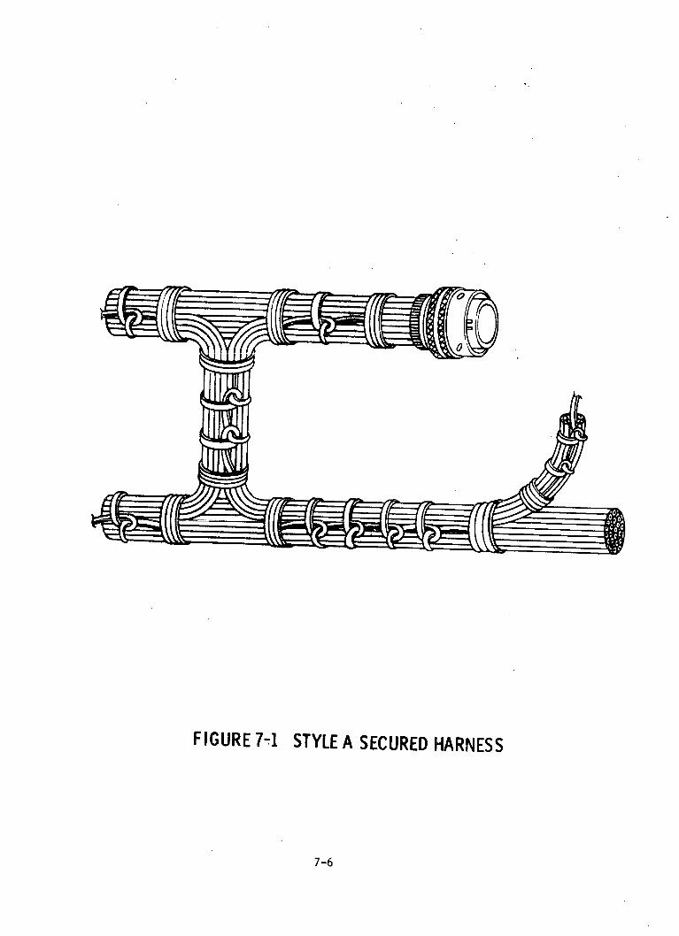
FIGURE 7-1 STYLE A SECURED HARNESS
7-6
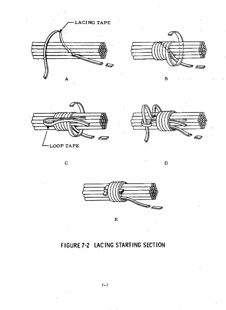
A
LLOOP TAPE
C D
E
FIGURE 7-2 LACING STARTING SECTION
7-7
B
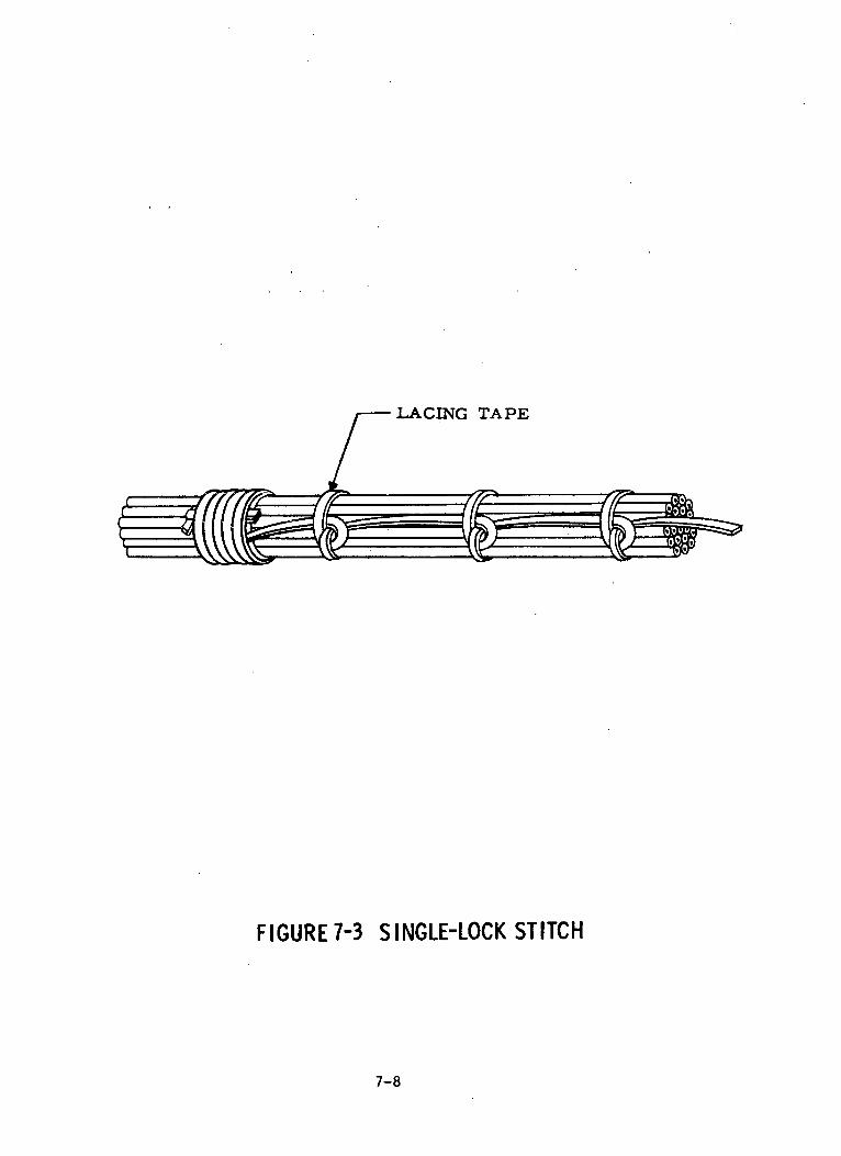
LACING TAPE
FIGURE 7-3 SINGLE-LOCK STITCH
7-8
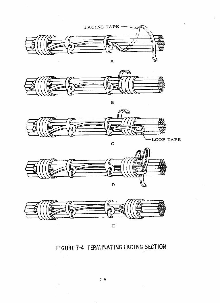
LACING TAPE
A
B
-- LOOP TAPE
D
FIGURE 7-4 TERMINATING LACING SECTION
7-9

A
B
C
D
FIGURE 7-5 LACING TAPE SPLICETERMINATION
7-i0

-TYPICAL LACETERMINATI ON
A
FIGURE 7-6 LACING BRANCHES OR BREAKOUTS
7-11
C.

FIGURE 7-7 STYLE B SECURED HARNESS
7-12

B
TERMINATING KNOT
FIGURE 7-8 SPOT TIE
FIGURE 7-9 SQUARE KNOT
7-13
0
A C
D F 4
A B
i __~~~~~~~~~~~~~~~~~~~~~~~~~~~~~I

SECTION 8
STRIPPING ELECTRICAL WIRE AND CABLE
8.1 GENERAL
The intent of this section is to establish techniques for the removal
of insulation front electrical wire and.cable. Several types of thermal
and mechanical wire stripping equipment are available in both manual and
automatic modes, but-only the acceptable manual methods shall be covered
in this section.- Regardless of the method used, automatic or manual, it
is essential thatthe stripped wire or cable meet the requirements contained
in the following paragraphs.
8.2 PROCESS CONTROL REQUIREMENTS
Prior to the stripping of the electrical wire and/or cable, verify that
all conductors have been cut to the required length and that wire and cable
insulation is free of nicks, cuts, or abrasions. When layout operations
precede stripping operations, the wires and cables shall be cut to the appro-
priate length necessary to preclude excessive wire or cable when collectively
terminated. Assure that the harness layout is in the correct configuration
and all wires and cables are free of kinks, excessive bends, etc. Verify
that shrinkable sleeving has been installed where applicable and that the
layout operations were successfully completed.
8.2.1 GENERAL PROCESS ACCEPTANCE CRITERIA
All methods that are used in stripping wires or cables shall be in
accordance with applicable standards and specifications. The stripping
operations shall be performed in such a manner that the conductor strands
are not severed or nicked. Minor longitudinal scratches and circumferential
nicks on the conductors shall be acceptable providing such scratches and
nicks do not penetrate through the plating. Wire stripping tools must not
cut, extrude, or otherwise damage the remaining insulation, but slight
dents or impressions left by the tool are acceptable. Frayed insulation at
stripped wire ends is unacceptable, although a few fibrous threads may be
allowed to remain providing they do not interfere or represent more than 10%
8-1

8.2.1 GENERAL PROCESS ACCEPTANCE CRITERIA (Continued)
of the total fiber stranding.
8.2.2 METHOD SELECTION
Thermal wire stripping tools shall be used, whenever possible, to remove
insulation from all types and sizes of wire. Non-adjustable, factory-set,
cutting type, mechanical strippers shall be used when thermal strippers
cannot be used. In the case of large wires or cables for which a conventional
stripper does not exist, a knife may be used to remove the outer insulation.
8.2.3 TOOL APPROVAL AND HANDLING
a. Assure that stripping tools are periodically certified. A sticker
or other device shall be attached to each tool indicating that the
tool has been certified and indicating the next recertification
due date. The lack of a certification sticker or symbol on a tool
indicates it is not approved for use under this specification.
b. Assure that during transportation and storage each tool is provided
protection from mechanical damage.
c. While in use, the tools should be arranged within easy reach of the
operator and each tool kept in a specified place. Only those tools
required for the current series of operations should be at the
operator's position.
d. In cases where a knife is used to remove the insulation material,
special care shall be used in handling and storage of the knife to
preclude personnel injury and/or damage to the wire/cable insulation.
8.2.4 OPERATOR QUALIFICATIONS
Personnel involved in stripping insulation from wire and cable shall
be trained to:
a. Be familiar with the requirements of this document and associated
documentation.
b. Receive instructions explaining the process requirements pertaining
to stripping of electrical wire and cable insulation.
c. Be skilled in the identification and use of tools required for
stripping of wire/cable insulation.
8-2
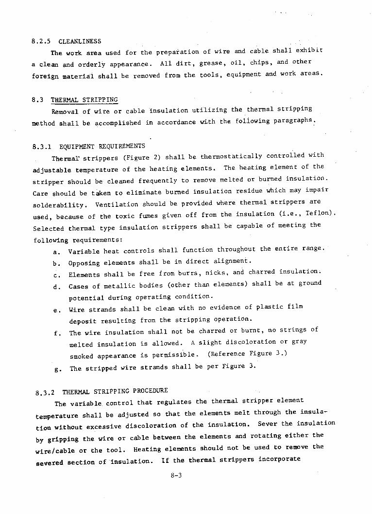
8.2.5 CLEANLINESS
The work area used for the preparation of wire and cable shall exhibit
a clean and orderly appearance. All dirt, grease, oil, chips, and other
foreign material shall be removed from the tools, equipment and work areas.
8.3 THERMAL STRIPPING
Removal of wire or cable insulation utilizing the thermal stripping
method shall be accomplished in accordance with the following paragraphs.
8.3.1 EQUIPMENT REQUIREMENTS
Thermal' strippers (Figure 2) shall be thermostatically controlled with
adjustable temperature of the heating elements. The heating element of the
stripper should be cleaned frequently to remove melted or burned insulation.
Care should be taken to eliminate burned insulation residue which may impair
solderability. Ventilation should be provided where thermal strippers are
used, because of the toxic fumes given off from the insulation (i.e., Teflon).
Selected thermal type insulation strippers shall be capable of meeting the
following requirements:
a. Variable heat controls shall function throughout the entire range.
b. Opposing elements shall be in direct alignment.
c. Elements shall be free from burrs, nicks, and charred insulation.
d. Cases of metallic bodies (other than elements) shall be at ground
potential during operating condition.
e. Wire strands shall be clean with no evidence of plastic film
deposit resulting from the stripping operation.
f. The wire insulation shall not be charred or burnt, no strings of
melted insulation is allowed. A slight discoloration or gray
smoked appearance is permissible. (Reference Figure 3.)
g. The stripped wire strands shall be per Figure 3.
8.3.2 THERMAL STRIPPING PROCEDURE
The variable control that regulates the thermal stripper element
temperature shall be adjusted so that the elements melt through the insula-
tion without excessive discoloration of the insulation. Sever the insulation
by gripping the wire or cable between the elements and rotating either the
wire/cable or the tool. Heating elements should not be used to remove the
severed section of insulation. If the thermal strippers incorporate
8-3

8.3.2 THERMAL STRIPPING PROCEDURE (Continued)
insulation gripping jaws, the jaws may be used to remove the insulation,
otherwise, the insulation shall be removed by gripping the section of insulation
between the thumb and finger and pulling with a twisting motion in the
direction of the normal lay of the wire strands.
8.4 MECHANICAL STRIPPING
Hand or machine precision cutting-type strippers shall be used to strip
fibrous insulation and other insulation that canrnot be removed by thermal
strippers. Cutting type strippers which permit operator adjustment shall not
be used; only non-adjustable, factory-set, cutting strippers, hand or
automatic types, shall be used for mechanical stripping. (Reference Figure 1.)
When using strippers with multiple stripping holes, for long production runs
on single wire sizes, unused holes in multiple dies should be blocked off to
prevent accidental use of an undersize hole. When available, tools equipped
with single hole dies are recommended.
8.4.1 TOOL REQUIREMENTS
Mechanical wire stripping tools utilized to remove non-metallic insulation
from wires or cables shall satisfy the following requirements:
a. The conductor strands of wire shall not be nicked, gouged, or cut,
but some scraping is permissible provided the base metal is not
exposed when viewed under five power magnification. (Reference Figure
4.)
b. The wire insulation shall not be punctured, crushed, or otherwise
damaged to such an extent that it does not pass the dielectric
acceptance requirements.
c. The ends shall be cut square and clean except for a few remaining
fibrous strands. Frequent amounts of remaining fibrous strands
within the 10% allowable requirement shall not be acceptable.
(Reference Figure 5.)
d. Stripping of shielded and jacketed cable shall not nick or cut shield
strands during removal of jacket insulation. Removal of shielding
shall not cause damage to the primary insulation. Irregular trimming
and partial combing-out of the shield strands is not acceptable.
(Reference Figure 6.)
8-4

8.4.2 TOOL CONTROL
The setting of the mechanical wire stripper and the work produced shall
be checked to assure that no nicks or cuts appear on the metallic conductor.
Cutting and stripping efficiency shall be maintained by replacing blades and
calibrating when necessar,. An approved periodic maintenance and calibration
schedule shall be instituted whereby stripping tools will be certified.
8.5 STRIPPING LARGE WIRES AND SHIELDED CABLES
When wire size, insulation material, or cable construction prohibits
the use of standard thermal or mechanical strippers, the insulation shall be
stripped with a sharp knife as illustrated (preferably an adjustable type)
in Figures 7 and 8. Wires and cables stripped with a knife must satisfy the
same quality requirements as those stripped with conventional strippers.
8.6 STRIPPING COAXIAL CABLES
Stripping of coaxial cable outer insulation jackets, internal insulations,
and braided shielding shall be accomplished to the dimensions prescribed in
the connector manufacturer's assembly instructions, when instructions are
not otherwise specified on the design drawing. Stripping methods shall be
in accordance with paragraphs 8.3, 8.4, or 8.5, as applicable.
8-5

FIGURE 8-1 MECHANICAL STRIPPER
REMOVABLE WIRE STRIPPER
i:=~- HEATING ELEMENTS
CONTROL KNOB
POWER SUPPLY
FIGURE 8-2 THERMAL STRIPPER
8-6

INSULATION STRIPPED BYTHERMAL METHODS SHALL
HAVE A MINIMUM OF EDGEFLASH WITH NO DAMAGETO THE CONDUCTOR, ASSHOWN.
ACCEPTABLE
CONTACT WITH THERMALSTRIPPER OUTSIDESTRIPPING AREA, DURINGINSULATION REMOVALOPERATION, MAY CAUSEINSULATION DAMAGE ANDEXPOSE WIRE STRANDS(ARROW).
UNACCEPTABLE
INSULATION EDGE FLASHING(ARROW) HAS NOT BEEN.REMOVED FOLLOWINGTHERMAL 'STRIPPING.
UNACCEPTA BLE
BURNT OR CHARREDINSULATION, AS SHOWN,IS THE RESULT OF EXCES-SIVE HEAT APPLICATION.
UNACCEPTABLE
FIGURE 8-3 THERMAL STRIPPING ACCEPTANCE CRITERIA
8-7
Alrrb.

NORMAL LAY CF STRANDS,DISTURBED DURINGSTRIPPING OPERATION,MAY BE RETWISTED TOTHE ORIGINAL WIRE LAY,IF WIRES HAVE NOT BEENDAMAG ED.
ACCEPTABLE
SEVERAL WIRE STRANDSARE CUT. THIS CONDITIONIS DUE TO THE WRONGHOLE SIZE USED IN THEMECHANICAL STRIPPER.
UNACCEPTABLE
WIRE STRANDS SHOWEVIDENCE OF A RINGEDCONDITION CAUSED BYSTRIPPER BLADES. OUTERSTRANDS ARE WEAKENEDAND MAY BREAK.
UNACCEPTABLE
WIRE STRANDS ARE NICKED,DUE TO MISALIGNMENT OFWIRE AND STRIPPINGBLADES. NICKED STRANDSREVEAL BASE METAL,AND MAY BREAK.
UNACCEPTABLE
FIGURE 8-4 MECHANICAL STRIPPING ACCEPTANCE CRITERIA
8-8
0
III
J11
IIIII
IL
I
I
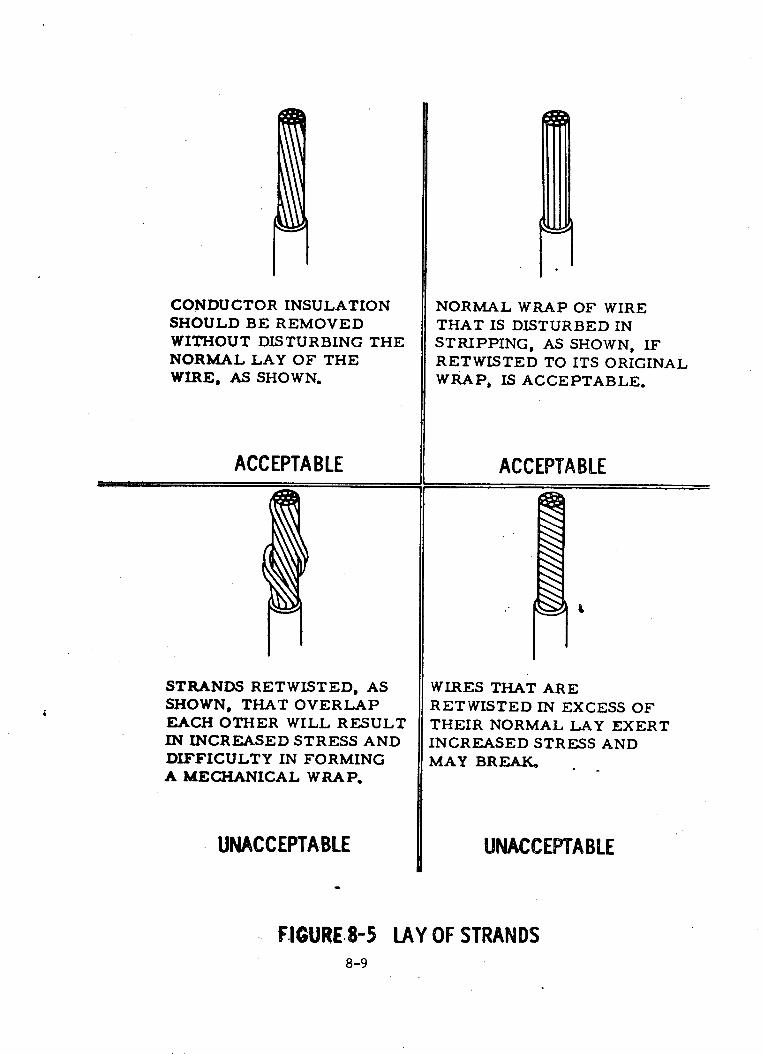
CONDUCTOR INSULATIONSHOULD BE REMOVEDWITHOUT DISTURBING THENORMAL LAY OF THEWIRE, AS SHOWN.
ACCEPTABLE
STRANDS RETWISTED, ASSHOWN, THAT OVERLAPEACH OTHER WILL RESULTIN INCREASED STRESS ANDDIFFICULTY IN FORMINGA MECHANICAL WRAP.
UNACCEPTABLE
NORMAL WRAP OF WIRETHAT IS DISTURBED INSTRIPPING, AS SHOWN, IFRETWISTED TO ITS ORIGINALWRAP, IS ACCEPTABLE.
ACCEPTABLE
WIRES THAT ARERETWISTED IN EXCESS OFTHEIR NORMAL LAY EXERTINCREASED STRESS ANDMAY BREAK.
UNACCEPTABLE
F.IGURE.8-5 LAY OF STRANDS8-9
i
hi
I
I

OUTER INSULATION (A) ANDSHIELDING (B) HAVE BEENPROPERLY REMOVED. NONICKS OR CUTS ARE VISIBLEON EITHER SHIELDING ORINNER CONDUCTORINSILATION (C).
ACCEPTABLE
VIEW SHOWS NICKED ANDCUT SHIELDING STRANDS,CAUSED DURING OUTERINSULATION REMOVAL.
UNACC EPTA BLE
VIEW SHOWS IRREGULARTRIMMING AND COMBING-OUT CONDITION OFSHIELDING STRANDS.
UNACCEPTABLE
VIEW SHOWS NICKED INNERCONDUCTOR INSULATIONCAUSED DURING SHIELDINGREMOVAL.
UNACCEPTABLE
FIGURE 8-6 INSULATION/SHIELDING REMOVAL8-10
II
i

FIRST CUT AROUND WIRE
CHECK CONDUCTOR STRANDSFOR DAMAGE
-- MAKE SECOND CUT ALONGTHE WIRE IF THE INSULATIONCANNOT BE PULLED OFFAFTER THE FIRST CUT
FIGURE 8-7 STRIPPING INSULATION FROM LARGE GAGE WIRES
MAKE FIRST CUT AROUND AND ALMOSTTHROUGH THE OUTER INSULATION
PEEL OFFOUTER JACKET
BRAIDED SHIELDING
- MAKE SECOND CUT ALONG THE CABLEIF THE INSULATION CANNOT BE PULLEDOFF AFTER FIRST CUT
* SHIELDED ANDJACKETED CABLE
FIGURE 8-8 OUTER JACKET REMOVAL8-11
SECTION 9
CABLE SHIELD TERMINATION
9.1 GENERAL
When shielded cables are utilized in wire harnesses, the outer cable
insulation and shield braid shall be terminated near the cable ends. The
following paragraphs describe the specific methods and criteria that shall
be used for termination of the cable shields.
9.2 REQUIREMENTS
When shield terminations are being made, extreme care shall be exercised
in selecting the proper method, materials, and tools to assure a reliable
joint. All shields that are terminated using ferrule rings shall be covered
with a snug, flexible, insulating sleeve. For the purpose of this document,
the term ferrule is defined as a ring used to terminate shielding. The
ferrule may be of solder or crimp type and is so constructed to permit
attachment of the cable shield(s) and shield return wire (if required)
between the ferrule sleeves.
9.2.1 PROCESS CONTROL REQUIREMENTS
Prior to application of cable shield terminations, verify that shield
braiding is not cut, nicked or scratched during removal of the cable jacket
insulation. Inspect all termination hardware (i.e., rings, ferrules,
insulated solder sleeves, etc.) to assure that they are of the correct type
and size, and are free of tranish, corrosion, or obvious damage. Verify
that ferrule placement is properly staggered to avoid excessive harness
diameter buildup and does not exceed the maximum allowable distance from
the connector backshell. (Reference Figure 1.)
9.3 CLASSIFICATION AND METHODS
Shield termination of cables shall be classified as either grounded or
ungrounded. Grounding of shield terminations shall be performed by means
of a shield return wire. In addition, shield braid that requires terminating
shall be prepared for ferrule application in accordance with any of the
9-1
9.3 CLASSIFICATION AND METHODS (Continued)
following methods:
a. Two-piece crimped ferrule - braided shield
b. Two-piece crimped ferrule - folded, combed shield
c. Two-piece crimped ferrule - multiple shielded conductors -
single folded shield
d. Solder sleeve ferrule - nominal shield coverage
e. Solder sleeve ferrule - maximum shield coverage
9.4 SHIELD TERMINATING
Shield terminations shall be in accordance with the applicable
wire list, or specifications; but the following criteria shall be us
a basis for acceptable practices:
a. Shield terminations shall be staggered in order to limit
buildup of harness diameter (refer to Figure 1).
b. Shield terminations shall not be positioned in a harness
so that they occur under cable clamps or within the potted
areas of electrical connectors.
c. Shield terminations for coaxial cables shall be in accordar
the connector manufacturer's instructions, when not specifi
applicable design drawings.
drawings,
;ed as
Ice with
ied on
9.4.1 INSULATION STRIPPING
When terminating a cable shield by either the grounded or ungrounded
method, the cable insulation shall be stripped from the cable as specified
in Section 8, "Stripping Electrical Wire and Cable". - The amount of insula-
tion removed is dependent upon the shield termination location and length
of shield braid required for the ferrule assembly, if grounding is required.
The removal of jacket insulation shall not cause nicks, cuts, or broken
strands. There shall be no evidence of cracked, split, punctured, or damaged
insulation on either the conductor(s) or jacket insulation
9.4.2 LOCATION
Cable shield terminations shall be located as indicated in Figure 1,
and the following:
a. On connectors with strain relief clamps, the measurement shall
be from the back of the strain relief clamp.
9-2

9.4.2 LOCATION (Continued)
b. On connectors without strain relief clamps, the measurement shall
be from the extreme back portion of the assembled connector.
c. On potted connectors, the measurement shall be from the extreme
back portion of the connector and/or potted area.
9.4.3 SHIELD BRAID CUTTING
Prior to insulating an ungrounded shielded cable, or installing a
ferrule set on grounded shielded cable, the braided shield must be cut at
the desired location. The procedure for cutting shielded braid is illustrated
in Figure 2, and shall be accomplished in accordance with the following
procedure:
a. Puff and squeeze the shield between the thumbs and forefingers
of both hands and form a ring around the conductor insulation
at the desired location.
b. With a pointed tool, spread the shield strands, making a hole
large enough to insert scissors.
c. Trim the shield with a pair of scissors.
9.5 TERMINATION OF FLOATING (UNGROUNDED) SHIELDED CABLES
When electrical circuit design does not require continuity of the cable
shield through a connector or to ground the shielded cable shall be terminated
by the floating shield method. This procedure is illustrated in Figure 3,
and shall be performed by stripping the insulation to the desired length and
trimming the shield braid to a length equal to one-half the cable diameter.
The shield braid should then be dressed back over the end of the outer cable
jacket insulation. After the shield braid has been dressed, cover the
termination with insulation sleeving as indicated in paragraph 9.7.1.
9.6 SHIELD RETURN WIRES
Where electrical circuit design requires continuity of the cable shield
through a connector or to ground, a shield return wire shall be used.
Shield return wires shall be fabricated from insulated, flexible stranded
type wire with the same temperature rating as the shielded cable. When the
insulated wire is to be connected to an electrical connector contact, the
wire shall be as dictated by the contact to which it is being connected,
otherwise, the shield return wire shall be AWG #22. Shielded return wires
formed by braiding or extending the shielding braid of a cable in the form
9-3

9.6 SHIELD RETURN WIRES (Continued)
of pigtails shall not be used.
9.6.1 LENGTH OF SHIELD RETURN WIRES
The minimum length of shield return wires shall be 2 inches. The
maximum length shall depend upon the staggered locations of the ferrules,
but an attempt shall be made to keep the length of the shield return
wire as short as possible, without causing undue tension.
9.6.2 ATTACHMENT OF SHIELD RETURN WIRES
· The stripped and fanned end of the shield return wire shall be positioned
between the shielding braid and outer ferrule and shall extend the full
distance of the ferrules to approximately flush with the end of the outer
ferrule. Shield return wires may be positioned at the forward or back end
of the ferrules. In general, the wires shall not cause strain on the
termination points and shall be tied so that they conform to the contour
of the harness, Minimum bend radius of shield return wires shall be three
times the wire outer diameter.
9.7 SHIELD TERMINATION INSULATION
Insulation sleeving shall be used to cover the ferrule set which joins
a shield return wire to a shield braid or the ungrounded, floating end of
a shield braid. The sleeving shall be of sufficient length and size to
ensure complete insulation of the shield termination assembly as illustrated
in Figure 4. Sleeving material may be heat- shrinkable or non-heat shrinkable
in sizes as required. Sleeving material shall withstand the same temperatures
and other environmental conditions to which the cable is subjected. Standards
for inspection of heat shrinkable sleeving are illustrated in Figures 5 and 6.
9.7.1 APPLICATION OF INSULATION SLEEVES
Heat deflectors shall be used on heat guns when there is adequate space
in the area where the sleeve is being shrunk. The deflector shall be as
recommended by the manufacturer of the heat gun. When using a heat gun with
a deflector, locate the sleeve near the center of the deflector while
applying heat. It will not be necessary to rotate the sleeve or gun since
the deflector will apply heat uniformly around the sleeve. Shrinking should
be performed in a well ventilated area, since toxic fumes can be given off
9-4
9.7.1 APPLICATION OF INSULATION SLEEVES (Continued)
from certain insulation materials. Teflon sleeves will change from a
translucent color to clear when the sleeves have reached the temperature
required for shrinking; at this time, the heat must be removed, allowing
the sleeve to shrink and return to its original co.or. All other types
of material will shrink as the heat is applied. When a heat gun without
a deflector is used to shrink sleeves, the heat gun or the sleeve must be
manipulated to assure that heat is applied uniformly in order to correctly
shrink the sleeve. it is preferable to use a deflector on heat guns since
a shorter shrinkage time is required and the shrinkage of the sleeve will
be more uniform. Heat shrinkable sleeves will shrink when the approximate
temperatures listed below are reached:
SLEEVING MATERIAL SHRINK TEMPERATURE
Teflon (TFE) 621°F
Teflon (FEP) 350°F
Kynar 350°0 F
Silicone Rubber 350°F
9.8 GROUNDED SHIELD TEPRMINATION HETHODS
All shielded cables that require electrical conductivity of the shield
by means of shield return wire shall be terminated with the application of
crimped ferrules or solder sleeve ferrules. The following criteria shall
be used as a basis for selecting the termination method:
a. Single conductor shielded cables and multi-conductor cables with
individually shielded conductors (with plain or shielded outer
covering), which require individual shield return wires, shall be
terminated using the braided shield method with crimped ferrules, or
solder sleeve ferrules (nominal or maximum shield coverage methods).
b. The folded and combed shield termination method shall be used when
the cable shielding is too tight to slide an inner ferrule between
the wire conductor(s) and shield, as described in the braided shield
method.
c. When design requirements permit a common shield return for individual
shielded cables within a larger cable, the single fold method of
termination shall be used.
9-5

9.9 TWO-PIECE CRIMPED FERRULE METHODS
Ferrule sets used for terminating grounded cable shields shall consist
of a "hard" inner ferrule and a "soft" outer ferrule, to preclude damage to
the inner cable insulation during crimping. Manufacturer's recommended
ferrule sizes shall be selected to match the cable size and to ensure proper
ferrule set assembly. Two-piece ferrules that are preassembled by the supplier
may be used. Color coding dye used for ferrule size designation shall be
removed prior to installation when systems contamination is a consideration
factor.
9.9.1 CRIMPING TOOLS
Crimping tools for ferrule sets shall be selected in accordance with the
manufacturer's recommendation to ensure proper compression of each ferrule
set on the shield braid. Tools shall have a valid calibration decal and
crimping tool number (part number or serial number) to allow recording on
the applicable permanent document, in accordance with MSC/MSFC-JD-001,
"Crimping of Electrical Connections".
9.9.2 STANDARDS FOR CRIMPED SHIELD TERMINATION
Crimp connections shall be inspected to determine that the shield strands
are contained within the crimp area or the termination device. There shall
be no sharp edges, peeled metal, cracks, burrs, or cuts on the termination
ferrule after crimping. The quality of the crimped shield terminations shall
be determined by a visual inspection, a maximum of 5 X magnification may be
used. (Reference Figures 7, 8, 9, and 10.) Normal flow of the metallic
ring, caused during the crimping operation, is acceptable.
9.9.3 BRAIDED SHIELD METHOD
The braided shield method of preparing cable shields for ferrule applica-
tion is illustrated in Figure 11, and shall be accomplished in accordance with
the following procedure:
a. Slide the outer ferrule over the cable.
b. Trim the shield braid to a length slightly in excess of the
inner ferrule length.
9-6

9.9.3 BRAIDED SHIELD METHOD (Continued)
c. Flare the end of the shielding by slightly rotating the
conductor(s) in a circular motion and slide the inner ferrule
beneath the shield braid. When the shielding is too tight to
slide the inner ferrule under, use the shield preparation
method outlined in paragraph 9.9.4.
d. Place the stripped and fanned end of the shield return wire
under the outer ferrule with one stripped end contacting the
shield braid directly over the inner ferrule.
e. Slide the outer ferrule over the inner ferrule and shield
return wire, crimp with the proper tool, and trim any braid
or wire strands extending past the front edge of the outer
ferrule.
f. Insulate the ferrule assembly as defined in paragraph 9.7.
9.9.4 FOLDED AND COMBED SHIELD TERMINATION METHOD
The folded and combed shield termination method for ferrule application
shall be used when cable shielding is too tight to slide an inner ferrule
between the wire conductor and shield, as described in the braided shield method.
Application of this procedure is illustrated in Figure 12, and shall be
accomplished in accordance with the following procedure:
a. Slide the inner ferrule over the shield braid and position it
against the end of the outer cable jacket.
b. Trim the shield braid to a sufficient length for folding back
over the entire length of the inner ferrule.
c. Comb the shield strands and fold back over the inner ferrule
with the strands distributed evenly around the periphery of the
ferrule.
d. Place the stripped and fanned end of the shield return wire under
the outer ferrule with one stripped end contacting the shield
braid directly over the combed shield and inner ferrule.
e. Slide the outer ferrule over the shield and shield return wire,
crimp with the proper tool, and trim any braid or wire strands
extending past the edge of the outer ferrule.
f. Insulate the ferrule assembly as defined in paragraph 9.7.
9-7

9.9.5 SINGLE-FOLD METHOD
The single-fold method of terminating shields for ferrule application
shall be used for multi-conductor cables where-each conductor is individually
shielded. Application of this procedure is illustrated in Figures 13 and 14,
and shall be accomplished in accordance with the following procedure:
a, Break the cable conductors out of the shields at the required
point as described in Figure 13.
b. Slide the inner ferrule over the shield braid and position so
the ends of the outer jacket insulation are located under the
inner ferrule.
c. Flatten the shield braid pigtails by hand and fold back over
the inner ferrule with the pigtails evenly distributed around
the periphery of the ferrule.
d. Place the stripped and fanned end of the shield return wire
under the outer ferrule with one stripped end contacting the
shield pigtails directly over the inner ferrule.
e. Slide the outer ferrule over the pigtails and shield return
wire, crimp with the proper tool, and trim any pigtail braids
extending past the edge of the outer ferrule.
f. Insulate the ferrule assembly as defined in paragraph 9.7.
9.9.6 TERMINATING TWO OR MORE INDIVIDUALLY TERMINATED SHIELDS TO A COMMON POINT
When the engineering drawing, wire list, or standard, specify that two
or more individually terminated shields are to be joined to a common ground,
interconnect the individual shield return wires as shown in Figure 15.
Interconnecting shield return wires (jumpers) used in this method shall be
fabricated using standard shield return wire termination methods.
9.10 SOLDER SLEEVE FERRULE METHODS
Solder sleeves used for terminating grounded cable shields shall consist
of a heat-shrinkable sleeve containing a preform of fluxed solder at the
center and a thermoplastic sealing ring in each end (reference Figure 16).
When placed over a cable shield and shield return wire (if required) and
briefly heated, the sleeve shrinks and the solder and thermoplastic inserts
melt, forming an insulated, encapsulated, soldered termination. Manufacturer's
recommended solder sleeve sizes shall be selected to match the cable size and
to ensure proper assembly.
9-8

9.10.1 APPLICATION OF SOLDER SLEEVE FERRULES
Heat guns equipped with manufacturer's recommended heat reflectors shall
be used for proper application of solder sleeves. The assembled unit is
)laced within the hot air stream of the heat gun reflector and heated as
required to shrink the outer sleeve and to melt the thermoplastic inserts.
'Seating is continued-until the solder ring changes from a dull grey color
to bright silver and flows toward the dams on either end of the solder sleeve.
NOTE: Shrinking should be performed in a well ventilated area, since
toxic fumes can be given off from certain insulating materials.
Just prior to the bright flow, the solder ring may collapse, but it is
important that the collapse of the ring be distihguished from the actual
flow of the solder, and that the unit remains -in the hot air stream until
the solder has actually changed color and flowed (reference Figures 17 and 18).
Total heating time is dependent 'on the size and the type of solder sleeve
and the size of the wire.
9.10.2 NOMINAL SOLDER SLEEVE SHIELD COVERAGE METHOD
The nominal shield coverage method utilizing solder sleeves is illustrated
in Figure 19, and shall be accomplished in accordance with the following
procedure:
a. Slide the solder sleeve over the cable.
b. Strip the outer cable insulation at staggered locations, starting
withl.5 inches and extending up to four inches of the connector
backshell.
c. Place the stripped and fanned end of the shield return wire under
the solder sleeve with the stripped end contacting the shield braid
as shown in Figure 19.
d. Apply heat to the solder sleeve as described in paragraph 9.10.1.
9.10.3 MAXIMUM SOLDER SLEEVE SHIELD COVERAGE METHOD
For maximum shield coverage, the shields shall extend up to the conductor
termination and floated by folding back over the conductor insulation and
covered with heat shrinkable tubing as described in paragraph 9.5, and as
illustrated in Figure 3. Openings shall be made in the outer cable insulation
and staggered starting with 1.5 inches and extending up to four inches from
the connector backshell for the installation of solder sleeves. Solder
sleeves and shield return wires shall be applied as described in paragraph
9-9

9.10.3 MAXIMUM SOLDER SLEEVE SHIELD COVERAGE METHOD (Continued)
9.10.2, and as illustrated in Figure 20.
9.10.4 EXAMINATION OF COMPLETED SOLDER SLEEVE
After application of heat, visually examine the solder sleeve joint for
proper heating of the solder by verifying that the solder ring has lost its
original configuration and no longer has a definite width. The solder joint
shall have a bright and shiny appearance with wetting of adjacent surfaces
(reference Figure 21). The completed solder sleeve shall be centered on the
splice or shield termination area and be free of cracks, punctures, splits,
or tears. The conductor and/or shield strands shall lie flat and shall not
protrude through the insulated sleeve.
9-10

w.4U) 6Q
3v,
z19
F4
.90C4 t,3
( .4
r / ;
-4 Oa
M °
1 '
.4F 4
U) H
.
am z
0 Z
z
s .Z
Z
°
E. 0
R 0
.w o 0~
~~
~clF
~~
~~
~~
~-W
q
9-1
1
0I---v zULJ
0I0Io0C,

*1
%RAIDED SHIELD
INNER JACKET-
INNER JACKET -
INNER JACKET
BRAIDED SH
B
BRAIDED SI
-OUTER JACKET
IELD
OUTER JACKET
WHIELD
·OUTER JACKET
FIGURE 9-2 REMOVING BRAIDED SHIELDING FROM CABLE
9-12

BRAIDED SHIELD
A
-SHIELD STRANDSNOTE: TRIM AND
AND FOLDCOMB BRAIDED SHIELD,OVER OUTER JACKET
CONDU CTOR
INSU LATION SLEEVEINSULATION
B
INSULATION SLEEVE (LOCATEAS SHOWN AND SHRINK)
CONDUCTOR
// _ -- PRIMARY INSULATION
' SHIELD STRANDS
COMPLETED FLOATING SHIELD TERMINATION
C
FIGURE 9-3 TERMINATION OF FLOATING BRAIDED SHIELD
9-13
JACKET

-CENTER SLEEVING OVER FERRULE SET
PRIMARY INSULATION
SHIELD RETURN WIRE
-OUTER JACKET
CENTER INSULATION SLEEVING AND APPLY HEAT
A
'INSULATION SLEEVE-OUTER JACKET
COMPLETED FERRULE SET
B
FIGURE 9-4 INSULATING SHIELD TERMINATIONS
9-14r. _

SLEEVING SHALL BE CUT TO LENGTHAND SHOULD BE CENTERED OVER THEFERRULE, AS SHOWN, AFTER SHRINK-ING.
ACCEPTABLE
Is I* ,
I3
I
SLEEVI NG (A) DOES NOT EXTEND1/4 INCH BEYOND THE FERRULE.
UNACCEPTABLE
CARELESS POSI TI ONI NG OF THE I N-SULATING SLEEVE (ARROW) HASCREATED A POTENTIAL SHORT ORGROUNDING OF THE SHIELD BRAID.
UNACCEPTABLE
FIGURE'9-5 STANDARDS FOR HEAT SHRINKABLE SLEEVING
9-15

SLEEVING SHALL BE FREE OFCRACKS OR SPLITS WHEN SHRUNK,IT SHALL FIT THE AREA SNUGENOUGH TO PREVENT ANY SLIP-PING OVER THE FERRULE, ASSHOWN. IT DOES NOT REQUIRE A -TIGHT SEAL.
ACCEPTABLE
SLEEVING HAS NOT BEEN SHRUNKENOUGH TO PREVENT IT FROMSLIPPING OFF THE FERRULE.
UNACCEPTABLE
SLEEVING HAS BEEN SHRUNK JUSTENOUGH TO MAINTAIN ITS POSIT-ION OVER THE FERRULE.
ACCEPTABLE
EXCESSIVE SHRINKING HAS COM-PRESSED WIRE INSULATION (A),AND CAUSED SEVERE SPLITTINGOF SLEEVING (B). THIS IS USUAL-LY THE RESULT OF USING THEWRONG SIZE SLEEVE.
UNACCEPTABLE
FIGURE 9-6 STANDARDS FOR HEAT SHRINKABLE'SLEEVING
9-16
1I
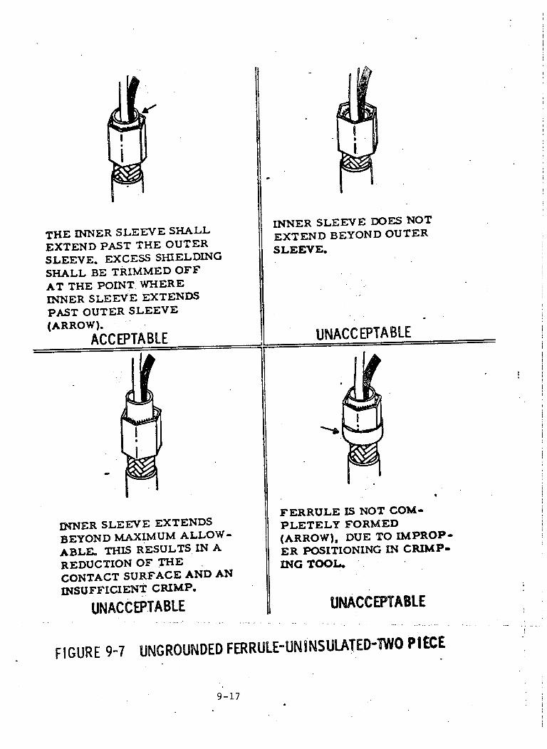
THE INNER SLEEVE SHALLEXTEND PAST THE OUTERSLEEVE, EXCESS SHIELDINGSHALL BE TRIMMED OFFAT THE POINT WHEREINNER SLEEVE EXTENDSPAST OUTER SLEEVE(ARROW).
ACCEPTABLE
INNER SLEEVE EXTENDSBEYOND MAXIMUM ALLOW-ABLE. THIS RESULTS IN AREDUCTION OF THECONTACT SURFACE AND ANINSUFFICIENT CRIMP.
UNACCEPTABLE
i
INNER SLEEVE DOES NOTEXTEND BEYOND OUTERSLEEVE.
UNACCEPTABLE
FERRULE IS NOT COM-PLETELY FORMED(ARROW), DUE TO IMPROP-ER POSITIONING IN CRIMP.ING TOOL.
UNACCEPTABLE
FIGURE 9-7 UNGROUNDED FERRULE-UNINSULATED-IWO PIECE
9-17
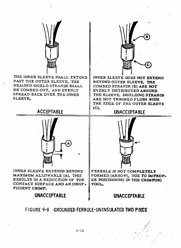
THE INNER SLEEVE SHALL EXTENDPAST THE OUTER SLEEVE. THEBRAIDED SHIELD STRANDS SHALLBE COMBED OUT, AND EVENLYSPREAD BACK OVER THE INNERSLEEVE.
ACCEPTABLE
01
INNER SLEEVE EXTENDS BEYONDMAXIMUM ALLOWABLE (A). THISRESULTS IN A REDUCTION OF THECONTACT SURFACE AND AN INSUF-FICIENT CRIMP.
UNACCEPTABLE
INNER SLEEVE DOES NOT EXTENDBEYOND OUTER SLEEVE. THECOMBED STRANDS (B) ARE NOTEVENLY DISTRIBUTED AROUNDTHE SLEEVE. SHIELDING STRANDSARE NOT TRIMMED FLUSH WITHTHE EDGE OF THE OUTER SLEEVE
(C).UNACCEPTABLE
14-"
FERRULE IS NOT COMPLETELYFORMED (ARROW), DUE TO IMPROP-ER POSITIONING IN THE CRIMPINGTOOL.
UNACCEPTABLE
FIGURE 9-8 GROUNDED FERRULE-UNINSULATED TWO PIECE
9-18
I

F -1
THE INSULATION GAP (A) OF BOTHTHE OUTER JACKET AND GROUNDJUMPER WIRE, SHALL NOT BEMORE THAN 3/16 * 1/16. THERESHALL BE NO EVIDENCE OF NICKS,
CUTS, OR ABRASION ON THESHIELDING OR JUMPER WIRE.
ACCEPTABLE
CABLE (B) HAS BEEN INSERTEDTOO FAR INTO CRIMPED CONNEC-TION. POSSIBLE SHIELDING WIREDAMAGE FROM STRIPPING WOULDNOT BE VISIBLE.
UNACCEPTABLE
FIGURE 9-9
THE CABLE INSULATION HAS BEFNSTRIPPED TO THE MAXIMUMALLOWABLE GAP. THERE IS NOVISIBLE SHIELDING DAMAGE.
ACCEPTABLE
CABLE INSULATION GAP HAS EX-CEEDED THE 1/4 INCH MAXIMUMALLOWABLE DIMENSION.
UNACCEPTABLE
JACKET INSULATION TO FERRULE REQUIREMENTS
9-19
I
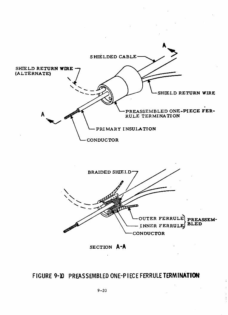
SHIELD RETURN(ALTERNATE)
A
A>SHIELDED CABLE
--SHIELD RETURN WIRE
-PREASSEMBLED ONE-PIECE FER-RULE TERMINATION
PRI MARY INSULATION
CONDUCTOR
BRAIDED
\ \\s
/-OUTER FERRUL PREASSEM-
\-- INNER FERRU BLED
CONDUCTOR
SECTION A-A
FIGURE 9-10 PREASSEMBLED ONE-P IECE FERRULE TERMINATION
9-20
WIRE
-_
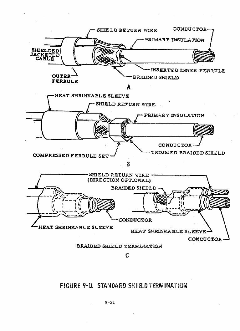
N11_B INSERTED XNNER FERRULE
FERRULEBRAIDED SHIELD
A-HEAT SHRINKABLE SLEEVE
I SHIELD RETURN 1WEIRE
- f=-PRIMARY INSULATION
CONDUCTOR
COMPRESSED FERRULE SETTRIMMED BRAIDED SHIELD
B-SHIELD RETURN WIRE -(DIRECTION OPTIONAL)
BRAIDED SHIELD-
'HEAT SHRINKABLE SLEEVE
CONDUCTOR'BRALDED SHIELD TERMIRATION
FIGURE 9-11 STANDARD SHIELD TERMINATION
9-21
WIRE CONCR
-PRIMY EINS1UTLTION
'' ' ' (X~--
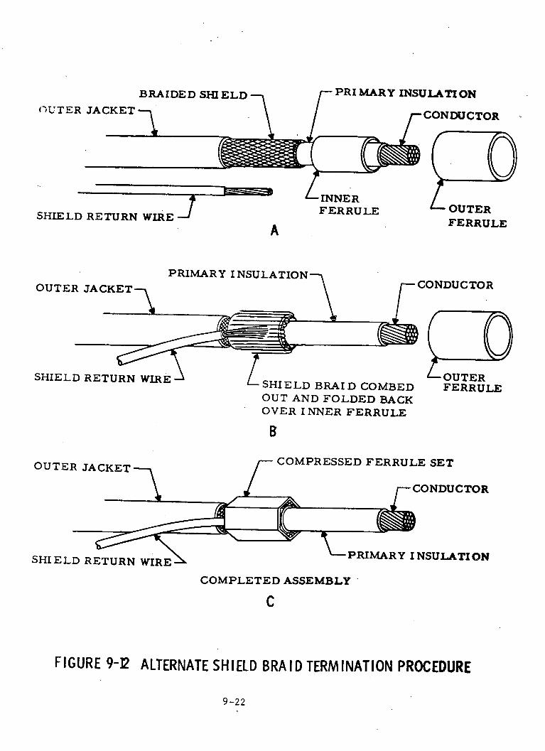
PRIMARY INSULATIONBRAIDED SHIELD
U , TER JACKET %
SHIELD RETURN WIRE 3
-INNERFERRULE - OUTER
FERRULEA
PRIMARY INSULATION
OUTER JACKET%
SHIELD RETURN WIRE SHIELD BRAID COMBED
-CONDUCTOR
OUTERFERRULE
OUT AND FOLDED BACKOVER INNER FERRULE
B
OUTER JACKET-
SHIELD RETURN WIRE
COMPRESSED FERRULE SET
PRIMARY I NSULATION
COMPLETED ASSEMBLY -
C
FIGURE 9-2 ALTERNATE SHIELD BRAID TERMINATION PROCEDURE
9-22
-bl~
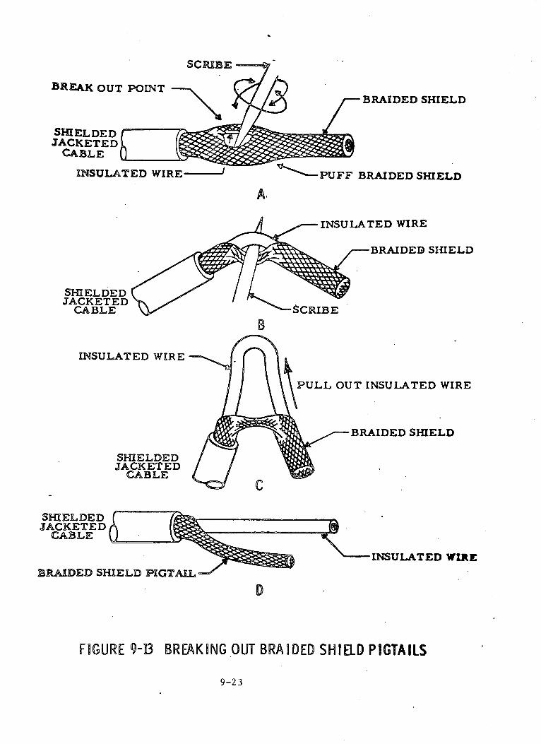
BREAK OUT POINT
SHIELDED [ 7JACKETE D
CABLE
INSULATED WIRE-
SHIELDEDJACKETED
CABLE
INSULATED WIRE
SHIELDEDJACKETED
CABLE
SHIELDEDJACKETEDCABLE
BRAIDED S-
- BRAIDED SHIELD
BRAIDED SHIELD
BRAIDED SHIELD
B
PULL OUT INSULATED WIRE
INBRAIDED SHIELD
X- INSULATED WIRE
D
FIGURE 9-B BREAKING OUT BRAIDED SHIELD PIGTAILS
9-23

BRAIDED SHIELD PIGTATILS CONDUCTORS
BRAIDED SHIELDS
A
OUTER --FERRULE
CONDUCTORS
, 7 X/~r
BRAIDED SHIELDS - L BRAIDED SHIELD PIGTAILS FOLDEDBACK OVER INNER FERRULE
B
/- CONDUCTORS
SHIELD RETURNWIRE
BRAIDED SHIELDS I
SHIELD RETURN - - - J
WIRE
BRAIDED SHIELDS
C F)UTERERRULE SHRINKABLE
SLEEVE
t\-CONDUCTORS
D
FIGURE 9-14 SHIELD TERMINATION OF MULTI-CONDUCTOR, SHIELDED CABLE
9-24
SHIE LDWIRE
RETURN
1�
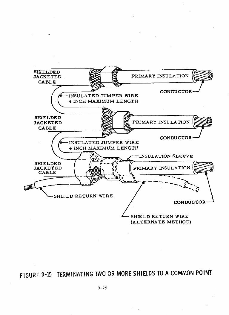
-INSULATED JUMPER WIRE4 INCH MAXIMUM LENGTH.
SHIELDEDJACKETED PRIMARY
CABLE
INSULATED JUMPER WIRE4 INCH MAXIMUM LENGTH
INSU LA TION
CONDUCTOR
SHIELD RETURN WIRE
CONDUCTOR'
SHIELD RETURN WIRE(ALTERNATE METHOD)
FIGURE 9-15 TERMINATING TWO OR MORE SHIELDS TO A COMMON POINT
9-25
CONDUCTOR-
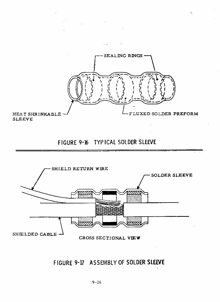
SEALING RINGS
H.AET SE.VP ANKABLESLE EVE
PREFORM
FIGURE 9-E6 TYPICAL SOLDER SLEEVE
SHIELD RETURN WIRE
SOLDER SLEEVE
SHIELDED CABLE
FIGURE 9-17
CROSS SECTIONAL VIEW
ASSEMBLY OF SOLDER SLEEVE
9-26
_~ ~ ~ ~ i --

HEAT SHRINKABLE SLEEVE.
SHIELD RETURN WIRE
SHIELDED CABLE
FLUXED SOLDER PREFORM-BRAIDED SHIELD -
ASSEMBLY JUST PRIOR TO SOLDER FLOW
HEAT SHRINKABLE SLEEVE -(SHRUNK TO REQUIRED FORM)
SHIELDED CABLE
SHI ELD RETURN WI RE-
-CONDUCTOR
BRAI DED SHIELD
SOLDER HAS FLOWED
CONDUCTOR OF THE SHIELD RETURN WIRE AND THE BRAI DED SHIELDCOMPLETELY COVERED BY SOLDER FLOW, AND PROPER FILLET BE-TWEEN CONDUCTOR AND BRAIDED SHIELD.
FIGURE 9-18 APPLICATION OF SOLDER SLEEVES
9-27

CONNECTOR
INSULATED/CONDUCTOR
SHIELD RETURN WIRE.
OUTER INSULATION-
1BRAIDED SHIELD
SHRUNK SOLDER SLEEVE \
4. 0 INCH (MAXIMUM)
FIGURE 9-19 SOLDER SLEEVE, NOMINAL SHIELD COVERAGE-CONNECTOR
-INSULATED CONDUCTORrSHRUNK SOLDER
SLEEVE-BRAIDED SHI ELD
FOLDED BACK-BRAIDED SHIELD
-SHRI NKAB ESLEEVE. INSULATION
ITER INSULATION
4.0 INCH (MAXIMUM)
-SHIELD RETURNWIRE
FIGURE 9-20 SOLDER SLEEVE, MAXIMUM SHIELD COVERAGE
9-28
I
P;

PROPERLY HEATED'
THE SOLDER HAS LOST ITS ORIGINALRING SHAPE. THE WIDTH OF THESOLDER CAN NO LONGER BE MEAS-URED. A GOOD FILLET OF SOLDEREXISTS BETWEEN THE SHIELD RE-TURN WIRE AND BRAIDED SHIELD.
ACCEPTABLE
UNDERHEATED
THE SOLDER HAS COLLAPSED ANDSTARTED TO MELT. HOWEVER, THEWIDTH AND SHAPE OF THE SOLDERBAND ARE STILL VERY WELLDEFINE D.
UNACC EPTA BLE
OVERHEATED
THE EXCESS HEAT HAS CAUSED THESOLDER TO WICK OR FLOW ALONGTHE BRAIDED SHIELD. THIS HASLEFT INSUFFICIENT SOLDER AT THEJOINT, AS INDICATED BY THE LACKOF A FILLET ALONG THE SHIELDRETURN WIRE AND BRAIDED SHIELD.
UNACCEPTABLE
FIGURE 9-21 SOLDER SLEEVE ACCEPTANCE CRITERIA
9-29
II -
I

SECTION 10
WIRE AND CABLE TERMTNAfII;,
Ih)1 I EIG':NI:AI.
This section establishes the requirements for crimping and soldering
of electrical terminations.
10.2 PROCESS CONTROL REQUIREMENTS
The methods for preparing and assembling the parts to be joined by
crimping or soldering, and the selection, calibration, use, and verification
of the tools shall conform to the following paragraphs. Regardless of the
process used (crimping or soldering), records shall be kept to provide
identification between the finished product, the operator, and the tools or
equipment utilized.
lu.2.1 CLEANLINESS REQUIREMENTS
Work areas shall be maintained in a neat orderly fashion, with no loose
material (trash, dust, oils, etc.) that can cause contamination of the crimped
or soldered connection. Working surfaces shall be covered with an easily
cleaned hard top, or shall have a disposable, non-corrosive covering. Smoking,
eating, and drinking at the work stations shall not be permitted.
10.2.2 OPERATOR QUALIFICATIONS
Personnel involved in wire termination processes shall be trained and
certified in the use of tools and equipment as described in MISC/MSFC JD-001,
"Requirements for Crimping of Electrical Connectors", or NHB 5300.4 (3A),
"Requirements for Soldered Electrical Connection", as applicable.
10.2.3 PROCESS VERIFICATION
Prior to performing wire/cable termination operations, verify that pre-
ceding operations such as wire/cable layout, cable shield terminations (where
applicable), and stripping, have been performed and verified in accordance with
applicable drawings and specifications. Make sure that wires/cables have not
been damaged and wire/cable has been cut and stripped at the correct location
for termination. In addition to the preceding process control requirements,
10 -1

10.2.3 PROCESS VERIFICATION (Continued)
the controls and procedures described in the following paragraphs shall be
iapplled, aa applicalle to the termination method.
10.3 CRIMP CONTACT TERMINATIONS
Crimping operations for connector contacts (pins and sockets), shall be
performed and controlled as described in the following paragraphs. Prior to
performing crimping operations, the operator shall review all applicable
materials, tools, and techniques which are planned for the work, to insure
compatibility with the manufacturer's instructions and/or operator's planning
procedures. The review shall cover each separate manufacturing step, and
shall consider the type of wire (number of strands), plating metal, type and
thickness of insulation, the type of contact (size, shape, and material), and
the tools (type and calibration) which are needed to perform the operation.
The criteria contained in this document, along with the requirements established
in MSC/MSFC JD-001, shall be used as a guideline for assurance of proper and
reliable crimp terminations.
10.3.1 CRIMP TOOLING
The crimp method for making electrical connections consists of compressing
the crimp barrel of the connector contact onto the wire or cable very tightly
so intimate metal-to-metal contact is achieved. Therefore, it is essential
that only factory set, non-adjustable crimping tools of the manual or power
driven type are used, so the process can be controlled and the crimp can be
easily and correctly made and reliably reproduced. Whenever practical, tools
that provide four indents, as illustrated in Figure 1, shall be utilized for
crimping connector contacts. In general, crimping tools should be selected
that contain the following features:
a. Provision for holding the contact in place while the wire or cable is
inserted and the crimp started.
b. A full cycle control so that the tool will not open and the contact
cannot be removed until the crimp is completed.
c. A bottoming feature which assures that the crimp is compressed to a
specified dimension before the full cycle control allows the tool to
open,
d. Proper size, weight, and shape for easy and efficient operation.
10-2

10.3.1 CRIMP TOOLING (Continued)
e. Strong construction and dependable action to assure consistent crimp
indention.
10.3.2 CALIBRATION AND CONTROL OF CRIMPING TOOLS
Crimping tools, both manual and power driven, shall be calibrated when
initially set up, for each specific wire size, contact size, and type material.
The crimping tool shall be calibrated and controlled in accordance with speci-
fication MSC/MSFC JD-001, "Requirements for crimping of Electrical Connections",
and the criteria contained in this document. To establish proper in-process
control, the following tests shall be performed upon sample crimped terminations
in production:
a, Tensile Strength - Tensile strength tests are performed to measure
the force required to fracture the crimp joint between wire/cable and
terminal. The tensile test is conducted by gripping the contact in
one jaw and the wire/cable in the other jaw of a dependable tensile
testing machine and pulling at a prescribed rate until fracture occurs.
The recommended tensile tester used to perform the pull tests shall
have an accuracy of + 1/2 pound per 50 pounds. The movable jaw shall
be adjustable to 1 inch per minute and shall be capable of maintaining
this speed at + 0.25 inch per minute. The terminal and wire/cable
must be. gripped in the jaws so the crimped area is not bent or other-
wise affected. Sometimes it may be necessary to provide special holding
fixtures so fracture does not occur at the jaws. It is advisable to
provide 6 inches of wire/cable between the jaws of the testing machine
so all of the wire/cable strands absorb the applied load. The connection
shall show no damage when subjected to a minimum load of 75 percent
of the wire/cable tensile strength. After determining that the joint
possesses minimum strength, the load shall be increased to failure.
The value of failure shall be recorded, together with whether the
failure was pull out, break in crimp, or break in wire.
bo Resistance Tests - The electrical resistance of a crimp termination
is measured to determine its conductivity. The measured value of
the crimp termination is compared to that of an equal length and size
of wire/cable used in the crimp operation and expressed as the relative
resistance for that particular wire/cable size. The relative resistance
of crimp to the wire/cable is determined by passing a specified current
10-3

i6 3 2 CALTB RlAION AID MU.>T O cQ : iu;.S s (ontin.ed)
through the scria-(o e--:ina and measurln.g the voltage drop. Properly
designed -nd assembled cr,:m, terinations will have resistance values
iow°Er than the wire/cahbe itsei'f
c. GO-NOGO Gaging - From t"e tenslie and resistance test results, a crimp
depth setting within the ailowabie tolerances can be established by
using the "CO9- " °NOGO' "ae sipecified fnr the contact size9 and the
wire/cable type and size. ic- gaging is p,.rformed by closing the
cr.imp tool handles to the bnttom of the stroke9 so the crimp dies are
butted and the tool ratchet is in the release position9 and inserting
3the :C,09 gage between fine .ind nters fror the protruding side of the
positioner. The gage shoulC pa-s through freely9 thereby indicating
that the indenters are not set too tight, This procedure is repeated
with the 1O1-CO", but the -a-ze chali not enter between the indenters.
This proves that the indenters are not set too loose. Once the
determination has been m-de that in the positive bottoming position
the indenters are set corr.ctly, then the ratchet release must be
checked by inserting the ' giaNV! gage be'tween the indenters and gently
closing the tool handles ,,ntii the indenters touch the gage. When
the handles are release., thone _ ol shall not bottom and shall not
return to the fully ope.n ?osition.
CAUTION: excessive hand Dressure during tool closure will crimp the
gage pin and caumcC possible damage to the indenter tips.
1)o 33 CRIMPED CONTACT TERMINATION PREPAR.ATIC
Before ottempting to produce cr.ir.oed ter.iinatio.ns9 the operator should
perform a review of the materiaiJs o zois, zand Zech;.liGues which are planned for
the work to ensure compatibility wi.h: ;h a plicable operations procedure. Upon
completion of the procedure reviewo Ctez-mine the wire/cable stripping length
required for the particular crimp cnta.c and remove the insulation using one
of the processes defined in Section 8 of this document. For wire sizes AWG 30
through AWG 109 the maximum insulation gap shall be P.qual to the outside
diagester of the wire being used. Fo7r larger wire sizes9 the gap shall not
exceed 1/4 inch. There shall be no minimum gap requirement, except that wire/
cable insulation shall not he crimped nt the cobnact barrel° Where the terminal
or contact is supplied with insulation supports, the wire/cable insulation
ahS hi enter into the support suff-icaen-rly so teat no bare wire is exposed.

10.3.4 CRIMPING PROCEDURE
Termination of the wire/cable into the contact shall be performed as
described in the following procedure:
a. Place the contact in the positioner and observe if it is held in
proper location. Usually the contact can be placed in the locator
and the tool handles closed partially until the crimp dies just
start to press on the contact, without compressing it. At this point
the ratchet will lock the handles in position.
b. Insert the stripped wire/cable in the crimp barrel until it bottons,
then push lightly to hold the wire/cable in the bottomed position.
If the contact has an inspection hole, the stripped wires shall be
visible in the hole. Do not push so hard that the wire/cable bends
or the contact moves. Exercise care to assure that all conductor
strands are inserted in the contact crimp barrel, and verify that
insulation clearance meets the requirements established in paragraph
10.3.3.
c. While holding the wire/cable in place, close the tool handles until
the crimp dies bottom or butt together. The handles may now be
released (they should open under their own spring pressure), and the
crimped termination removed (reference Figure 2).
10.3.5 CRIMP TERMINATION PROCESS VERIFICATION
After crimping, verify and record identification of the crimping tool and
operator. Contacts shall be inspected to verify that the wire conductors are
visible through the inspection hole (when applicable) and insulation does not
extend into the crimped portion of the contact barrel. Assure that the maximum
insulation gap does not exceed the outside diameter of the wire. The crimping
indentations shall be in the proper portion of the barrel and there shall be
no cracks, splits, or flaked plating on the crimped contacts. Also, the contacts
shall not be bent.
10.4 SOLDER CONTACT TERMINATIONS
Wires and cables to be terminated in solder type connectors shall be
prepared and soldered in accordance with the procedures, requirements, and
controls established in NHB 5300.4 (3A), "Requirements for Soldered Electrical
Connections", and the following paragraphs.
10-5

10.4.1 SOLDERING EQUIPMENT AND MATERIALS
The solder method for making strong electrical connections requires
heating the solder joint to a temperature of 500° - 550° F. for 1 to 2 seconds
and applying rosin cored solder to complete the solder connection. Therefore,
it is essential that the size, wattage, and shape of the soldering iron be
carefully selected to approach these conditions as closely as possible. When
the tip is applied to the connection joint, it should rapidly heat the joint
to soldering temperature. The solder used for completing the joint should
contain a core of rosin flux to aid solder flow.
10.4.2 WIRE PREPARATION
Prior to soldering wires or cables to connector contacts, the wires/cables
shall be pre-tinned to assure solderability. Tinning of the wire/cable should
extend only far enough to take full advantage of the connector solder cup and
should be accomplished as described in the following procedure:
a. Determine the wire stripping length required for the particular
solder termination and remove the insulation as defined in Section 8
of this document.
b. Add a small amount of solder to the tip of the iron, and then place
the wire on top of the solder and allow to heat.
c. When the wire has reached the temperature of the iron, solder will
flow into the strands. At this time, a small amount of solder is
applied to the wire. Solder is then allowed to flow until the wire
has absorbed enough to tin every strand.
NOTE: Tinning may be accomplished by dipping the wire into a
solder pot.
10.4.3 CONNECTOR PREPARATION
Prior to soldering wires/cables to connector contacts, the connector shall
be disassembled (i.e., backshell, ferrule, and grommet), when applicable.
Preparation of the connector shall include cleaning of both sides of the
connector to assure that the surfaces are free of oil, dirt, grease, and any
foreign materials. If present, these substances shall be removed by wiping
with a clean lint-free cloth dampened with a suitable cleaning solvent,
followed by wiping with a clean dry cloth. Also, a clean soft brush may be
used to remove loose contaminates.
10-6

1 .4.3 CONNECTOR PREPARATION (Continued)
NOTE: When tightening or loosening threaded parts or connectors, supporr
all plug assemblies by mating with the proper receptacle, or by
holding them with an approved plug wrench.
After the wires/cables have been prepared and are ready to be soldered
to the connector contacts, slide the connector, wire guide grommet, backshell,
and wire sealing grommet (when required), onto the wires/cables a sufficient
distance so as not to interfere with the soldering operation.
NOTE: If difficulty is encountered in passing wires through the sealing
grommet, the wire may be cut on an angle of 45 degrees. In this
case, stripping and tinning of the wire is performed after passing
the wire through the grommets.
10.4.4 JOINING WIRE/CABLE TO CONNECTOR
The connection should be firmly mounted with the open end of the cups
facing the operator. The wires should be soldered in rows, progressing from
bottom to the top. To properly solder the wire or cable to a connector, the
following procedure is recommended:
a. Insert a small piece of solder in the cup and heat by holding the
flat side of the soldering iron against the lower side of the cup,
until the solder is completely melted. Keep the heat on the terminal
until all trapped flux comes to the surface.
b. Insert the tinned wire into the molten solder until the wire bottoms
in the cup. The conductor should be in contact with the back wall
of the cup, and the end of the insulation should be far enough from
the soldered joint that the insulation cannot be embedded in the solder,
yet not so far as to permit a short circuit between two adjacent. wires.
In general, the length of the gap should be a distance equal to
approximately the wire diameter.
c. Remove the iron and hold the conductor steady until the solder cools
and hardens. A smooth fillet should be formed between theconductor
and the inner wall of the cup, as illustrated in Figure 31, All outside
strands should be clearly discernible adjacent to the insulation.
d. After the solder has solidified, clean the joint using a bristle brush
dipped in isoprophyle alcohol or other approved solvent to remove flux
residues.
10-7

10.4.4 JOINING WIRE/CABLE TO CONNECTOR (Continued)
e. After the solder connection has been verified, slide a piece of
insulation tubing over the soldered connection. When the connector
is to be potted, a protective sleeve over the wire and contact shall
not be installed.
f. Assemble the connector as described in Section 11 of this document.
10.4.5 SOLDERED CONTACT PROCESS VERIFICATION
After soldering, record identification of the operator. Soldered contacts
shall be inspected to verify that the solder joint meets the requirements of
NHB 5300.4 (3A). The quality of the soldered connection can be determined by
visual inspection. Wires should not be pulled or bent, nor force exerted on
the connection to test the mechanical soundness of the connection. Sin e the
wire should not be bent or forced, it is necessary to inspect in steps when
later assembly will make the solder joint impossible to inspect.
10-8

CONTA(:T (PINOR S'i'IE'Tr)
"' CONTACT
-INDENT DIE (4 PLACES)
;i ,-- \:. ;NDUCTOR
ACR[ Mi'iFT nCONTACTSECTION-INSULATED
CONDUCTOR
FIGURE 1]-1 FOUR INDENT CRIMP
WIRE CONDUCTOR VISIBLE--\IN INSPECTION HOLE
CONTACT (PINOR SOCKET)
CRIMPING TINDENTATI(
INSULATION BUTTED AGAINSTENTRY OF CONTACT
OOL INSULATEDON CONDUCTOR
FIGURE 10-2 TYPICAL CRIMPED CONTACT
CONTACT (PINOR SOCKET)
SOLDER
INSULATEDCONDUCTOR
FIGURE 10-3 PROPER SOLDER CUP TERMINATION
10-9

SECTION 11
CONNECTOR ASSEMBLY
11.1 GENERAL
This section describes the procedures and process controls relative
to installation of crimped contacts into connectors, and assembly of both
crimp and solder tvpF connectors. Elements relative to termination of
wires/cables by crimping or soldering are contained in Section 10 of this
document and should be referred to, prior to connector assembly operations.
11.2 PROCESS CONTROL REQUIREMENTS
Prior to performing the wiring or assembly of any connector, verify
that all wire and cable has been cut, stripped, and terminated (when
applicable) in accordance with the previous process requirements. Visually
examine each connector and associated hardware to assure that the contacts
are not bent or recessed, the finish is not damaged, and the interface
grommet, wire termination and rear insert are free from foreign material,
grease, dirt, etc. Check grommet area for imperfections such as mold
flash, cuts, gouges, or obvious damage to the sealing area of the connector.
Verify that connector coupling devices are free of burred or scored coupling
nut threads or damaged clocking key(s).
11.2.1 CONNECTOR PROTECTION
All connectors shall have caps or other protective devices installed
throughout all stages of fabrication and testing, except when connected
with mating connectors, or during individual connector testing. 'When caps
are removed for pin insertion, testing, cleaning, etc., the caps shall be
replaced promptly after the operation is completed.
11.2.2 CONNECTOR CLEANING
Prior to assembly or after disassembly of a connector, the contacts
and inside surface of the connector shall be kept free of all oil, dirt,
grease, and any other foreign material. If present, these substances shall
11-1

11.2.2 CONNECTOR CLEANING (Continued)
be removed by wiping with a clean lint free cloth dampened with a suitable
cleaning fluid, followed by wiping with a clean dry cloth. Also, a clean
soft brush may be used to remove loose contaminates on interfacial seals.
11.3 ASSEMBLY OF CRIMP TYPE CONNECTORS
Preparatory to inserting contacts into crimp type connectors, the
.operator shall assure that the contact insertion and removal tools are of
the correct type, and are in acceptable working condition. Damaged tooling
shall not be used. Insertion and removal tools shall be inspected prior
to, and after completion of work on each connector. In addition, tooling
fixtures shall be provided to support the wires/cables and connector while
installing the crimped contacts. After applicable tools have been obtained
and verified, the wires/cables shall be inserted in the connectors, and
connectors assembled, as described in the following paragraphs.
11o3,1 CONTACT INSERTION (REAR ENTRY TYPE)
After the contacts have been crimped (Reference Section 10) to the
wires/cables and are ready to be installed in the connector, slide the
connector, wire guide gronmnet, and the back shell assembly onto the wires.
NOTE: The backshell assembly supplied with the connector shall be
installed unless otherwise specified on the applicable
engineering drawing.
To install the contacts in the connector, the insertion/extraction
tool is snapped around the wire insulation with the tip of the tool butting
against the rear shoulder of the contact. The contact, axially aligned with the
cavity, is then inserted into the proper cavity in the rear of the connector
and pushed forward until it bottoms in the insert. When inserted, the tangs
on the retaining clip will snap into position behind the contact shoulder.
A slight "click" should be heard at this point. The tool is then removed
leaving the contact held securely in the insert. Continue in a like manner
to install the remainder of the contacts. Spare contacts shall be installed
in unused insert cavities. It is recommended that the center contacts be
inserted first then continue working outward. When completed, a visual
inspection shall be made at the mating end of the connector to be sure all
contacts are properly inserted and secured to an equal distance.
CAUTION: Do not use insertion tools that have damaged insertion tips.
Visually inspect the tool to insure that tool tips are not
11-2
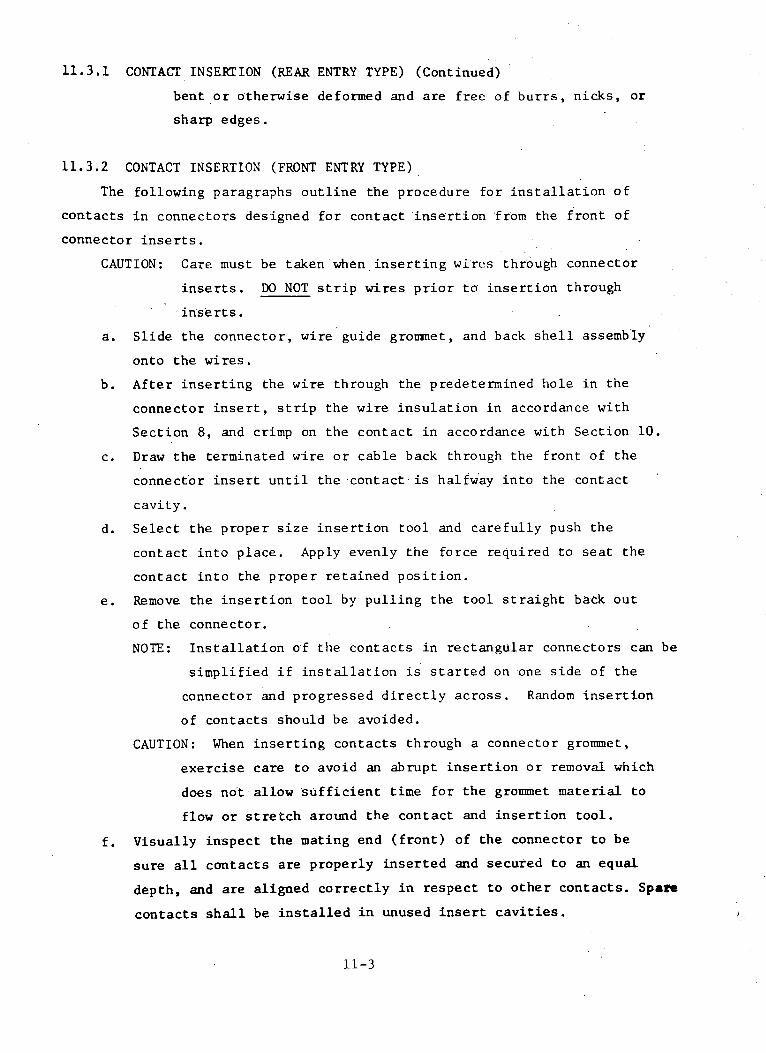
11.3.1 CONTACT INSERTION (REARENTRY TYPE) (Continued)
bent or otherwise deformed and are free of burrs, nicks, or
sharp edges.
11.3.2 CONTACT INSERTION (FRONT ENTRY TYPE)
The following paragraphs outline the procedure for installation of
contacts in connectors designed for contact insertion from the front of
connector inserts.
CAUTION: Care must be taken when inserting wires through connector
inserts. DO NOT strip wires prior to insertion through
inserts.
a. Slide the connector, wire guide grommet, and back shell assembly
onto the wires.
b. After inserting the wire through the predetermined hole in the
connector insert, strip the wire insulation in accordance with
Section 8, and crimp on the contact in accordance with Section 10.
c. Draw the terminated wire or cable back through the front of the
connector insert until the contact is halfway into the -contact
cavity.
d. Select the proper size insertion tool and carefully push the
contact into place. Apply evenly the force required to seat the
contact into the proper retained position.
e. Remove the insertion tool by pulling the tool straight back out
of the connector.
NOTE: Installation of the contacts in rectangular connectors can be
simplified if installation is started on one side of the
connector and progressed directly across. Random insertion
of contacts should be avoided.
CAUTION: When inserting contacts through a connector grommet,
exercise care to avoid an abrupt insertion or removal which
does not-allow sufficient time for the grommet material to
flow or stretch around the contact and insertion tool.
f. Visually inspect the mating end (front) of the connector to be
sure all contacts are properly inserted and secured to an equal
depth, and are aligned correctly in respect to other contacts. Spare
contacts shall be installed in unused insert cavities.
11-3

11.3.3 SEALING OF UNISED CONNECTOR GROMIET HOLES
Every unused grommet hole shall be filled with a sealing plug. The
sealing plug shall be inserted by hand. (Reference Pigure 1.)
11.3.4 BACKSHELL INSTALLATION
Slide the backshlell forward and hand tighten to connector shell, making
sure that the wire scaling grommet does not become distorted, during the
tightening process (Reference Figure 2). For clocking of angle connector
bacKshells, a maximum deviation of +150 (degrees) from the specified clocked
position shall be allowed (Reference Figure 3).
11.3.5 STRAIN RELIEF OR CABLE GUIDE TYPES
All connectors that have strain relief or cable guide clamps shall have
a grommet or other approved protective material installed between the wire
bundle and the wire guide or strain relief clamp. This is to prevent chafing
and to maintain the relative position of the wiring at the cable exit.
Cushioning shall be applied on straight cable runs as well as on cable runs
that exit at an angle from wire guides or strain relief clamps. Allow
sufficient slack within the backshell cable guide clamp so that tightening
the cable clamps will not place a strain on the terminations or cause a
visible opening between the wire and the grommet sealing webs. (Reference
Figure 4.)
11.3.6 TIGHTENING CONNECTORS
Connectors with threaded couplings shall be tightened, as far as travel
permits, by hand to permit proper alignment and prevent damage to the threads.
Support the connector with a mating connector or connector body, except base
type, as illustrated in Figure 5. Specified torquing shall then be accomplished.
11.3.7 CRIMP TYPE CONNECTOR PROCESS VERIFICATION
Examine the completed connector to assure that all applicable provisions
of this document and applicable engineering documents are complied with.
Particular care shall be exercised to assure that the assembled connector is
free of such defects as:
11-4

11.3.7 CRIMP TYPE CONNECTOR PROCESS VERIFICATION (Continued)
a. Imperfections in the grommets extending into the chamfer (wire
sealing) area.
b. Obvious splits, cuts or gouges of the grommet.
c. Missing or improper "o" ring.
d. Connector contacts with cracked or flaked plating, tarnished or
corroded surfaces.
e. Recessed or protruding contacts, or missing contacts.
f. Bent or mis-aligned pins.
g. Visible dirt, grease, or other foreign materials.
h. Connector coupling devices that are loose, binding, or have burred
or scored coupling threads.
i. Damaged clocking key(s).
j. Strain relief clamps with burrs or sharp edges, excessive thread
protrusion, or backshell over/under torqued.
k. Protective finishes that are scratched, dented, or damaged so that
the base metal is exposed.
1. Missing or wrong size protective dust caps.
m. Missing sealing plug in grommet.
11.4 ENVIRONMENTALLY SEALED SOLDER TYPE CONNECTORS
Preparatory to the wiring of the connector, disassemble the connector
by removing the grommet compressing sleeve retaining screws, grommet com-
pressing sleeve or braid retaining adapter, sealing grommet and clamping nut;
remove the items in the aforementioned order. On potted type connectors,
remove the potting end bell. Mate the connector with a dummy or actual mating
part during the disassembly process.
11.4.1 WIRE/CABLE INSTALLATION
Prior to soldering the wires in the connector, the connector shall be
appropriately fixtured so that during and after the soldering process, the
wires are axially aligned with the connector contacts. Feed the wires through
the compressing sleeve or connector adapter and then through the sealing
grommet and clamping nut. Wires must pass through the grommet hole which
corresponds to the location of the contact to which the wires will be soldered.
Match the letters on the grommet with the letters on the insert so that the
grommet and wires are properly aligned. On potted type connectors, feed the
wires thru the end bell.
11-5

11.4.2 SOLDERING OF WIRES/CABLES
After the connector has been disassembled, located in an applicable
fixture, and wires/cables passed through the grommet, the wires/cables shall
be soldered to the connector contacts in accordance with the requirements of
paragraph 10.4 of this document. All unused sealing grommet holes shall be
filled with the sealing plugs furnished with each connector. The plugs shall
be installed as shown in Figure 1, at the time of connector assembly.
1.1.4.3 CONNECTOR ASSEMBLY
Carefully examine the rear of the connector insert for foreign particles
and wire strands, and to make sure that each bared conductor is not kinked or
bent. Assemble the connector as described in paragraphs 11.3.4, through 11.3.6.
11.4.4 SOLDER TYPE CONNECTOR PROCESS VERIFICATION
Examine the completed connector to assure that all provisions of this
document and applicable engineering documents are complied with. Particular
care shall be exercised to assure that the assembled connector is free of
such defects as:
a. Imperfections in the interfacial grommet extending into the chamfer
(wire sealing) area.
b. Obvious splits, cuts, or gouges of the grommet.
c. Missing or improper "o" ring
d. Connector contacts with cracked or flaked plating, tarnished or
corroded surfaces.
e. Bent or mis-aligned pins.
f. Visible dirt, grease, solder flux, or other foreign materials.
g. Connector coupling devices that are loose, binding, or have burred
or scored coupling threads
h. Damaged clocking key(s).
i. Strain relief clamps with burrs or sharp edges, excessive thread
protrusion, or backshell over/under torqued.
j. Protective finishes that are scratched, dented, or damaged, so
that the base metal is exposed.
k. Missing or wrong size protective dust caps.
11-6

11.5 ASSEMBLY OF COAXIAL CONNECTORS
The assembly of coaxial contacts and connectors shall be accomplished
as defined in the applicable manufacturer's instructions; however, the
manufacturer's instructions must not be relied on for final instruction.
Zktail instructions must be derived through process engineering, for the
materials specifically involved. Process engineering shall result in a
coaxial connector/cable assembly of the highest relialility. Disassembly
of samples shall assure that the torquing requirements are sufficient, the
stripping and trimming dimensions are optimum, and that all applicable
materials are appropriately placed. Both soldered and crimp type contact
terminations are acceptable. Cables shall be stripped, prior to termination,
as described in Section 8 of this document. The cable termination operation
(crimp or solder) shall be performed and controlled by the requirements
established in Section 10 of this document, as applicable. Regardless of
the type of coaxial connector used, or the method of termination (crimp or
solder), the process verification standards established in the following
paragraph shall apply.
11.5.1 COAXIAL TYPE CONNECTOR PROCESS VERIFICATION
Examine the completed connector to assure that all applicable provisions
of this document and applicable engineering documents are complied with.
Particular care shall be exercised to assure that the assembled connector is
free of such defects as:
a. Tarnished or corroded contacts.
b. Bent or misaligned pins.
c. Visible dirt, grease, solder flux, or other foreign material.
d. Coupling device that is loose, binding, or damaged.
e. Protective finishes that are scratched, dented, or damaged so that
the base metal is exposed.
11-7

.4. T TOP
SEALING PLUG BODY
o ojl -CAREFULLY INSERT SEALINGPLUG BODY INTO GROMMETSEAL WIRE ENTRY HOLEUNTIL BOTTOM OF SEALINGPLUG HEAD IS CLOSE TO THESURFACE OF THE GROMMET.
FIGURE 11-1 SEALING PLUG INSTALLATION
*--STRAIN RELIEF CLAMP SHALLNOT BOTTOM OUT.
-GROMMET
FIGURE 11-2 STRAIN RELIEFCLAMP
11-8

360000
600
2700° 1900
' 120°
CONNECTOR VIEWED FROM REAR
FIGURE 11-3 ALIGNMENT OF 900 CONNECTORS
NO GAP ALLOWED BETWEEN WIREINSULATION AND FIRST SEALING WEB.
BACKSHELL CLAMP /
CONDUCTORS -. Js
CONNECTOR
FIGURE 11-4 ALLOWABLE CONDUCTOR DEFLECTION
11-9
· , , . .

FIGURE 11-5 BASIC TYPES OF CONNECTOR HOLDING DEVICES
11-10
I o
I/
I
Ii

SECTION 12
POTTING ENCAPSULATION
12.1 GENERAL
This section establishes the standard process for potting electrical
connectors used in the fabrication of harness assemblies, by using epoxy resin
potting compositions. The criteria contained in this section conforms to, and
shall be used in conjur,ncion with all requirements of MSFC-PROC-196, "Potting
Cable Assemblies Using Epoxy Resin Compounds".
12.2 PROCESS CONTROL REQUIREMENTS
Prior to the potting operation, verify that the harness assembly bears
evidence of inspection acceptance for compliance to design requirements,
workmanship, and electrical testing. Care shall be taken to assure that all
loose wire strands, solder particles, and other foreign material, such as
oil, dirt, or grease, has been removed from the connector and cable harness
areas to be potted. If contaminants are present, they shall be removed by
wiping with a clean lint-free cloth, dampened with a suitable cleaning solvent,
followed by wiping with a clean dry cloth. When necessary, a clean soft
bristle brush may be used to remove loose contamination on interfacial
connector seals. Verify that connector coupling rings (when applicable)
rotate freely, and all connector contacts are properly aligned and not
recessed or protruding.
12.2.1 CONTROL AND CLEANLINESS OF POTTING FACILITY
The potting facility shall be isolated from such contaminants as dust,
metallic particles, water, oil, and grease. Bench tops shall be protected
from spillage by disposable paper coverings, and floors shall be cleaned
frequently with an acceptable cleanser. The temperature of the potting
facility shall be maintained at 24 + 2 degrees Celsius; and the relative
humidity shall not exceed 55 percent. Adequate ventilation shall be provided
to accommodate the volume of compounds, solvents, and primers being used.
Forced-draft ventilation, where toxic fumes are generated, is necessary and
fumes shall be drawn away from the operator and vented to the outside.
12-1

12.2.2 EQUIPMENT
The potting area should be equipped with air pressurization equipment
capable of delivering moisture-free air (maximum 90 psig), and a vacuum system
capable of producing a differential pressure for removing trapped air from
Lhe potting compound. Accurate weighing equipment shall be provided for
measuring the epoxy constituents. The injection gun shall be either a manual
or air-operated calking gun equipped with a disposable plunger, liner, and
nozzle. In addition, holding racks should be available to hold the harness
components rigid and in proper alignment.
12.2.3 HANDLING PRECAUTIONS
All personnel that are engaged in potting encapsulation shall demonstrate
proficiency in producing high quality end items, and be trained in proper
handling procedures. In general, the chemicals involved are safe when properly
handled by trained and qualified personnel, but when carelessly handled, the
materials utilized for potting may cause severe physiological reactions. The
following criteria shall be implemented, in conjunction with manufacturer's
instructions, to insure safe handling procedures:
a. Avoid contact with solvents, primers, and compounds with the skin.
Protective clothing shall be changed when soiled by potting materials.
Special care shall be taken to prevent contact with open breaks on
the skin.
b. Avoid ingestion and inhalation of vapors.
c. If the eyes are accidentally contaminated, flush with water and
obtain medical attention immediately.
d. Areas of the skin exposed to solvents, primers, and compounds shall
be cleaned with an approved cleaner and then with a nonabrasive soap
and clean water, Personnel shall not smoke or eat until after
thorough cleansing of exposed skin areas.
e. No smoking or open flames shall be allowed within 25 feet of an
operation where compounds, primers, and solvents are being used.
"NO SMOKING"' signs shall be displayed in conspicuous places.
12.3 HARNESS PREPARATION
To insure proper adhesion of the potting compound to all components of the
12-2

12.3 HARNESS PREPARATION (Continued)
connector, the inner body of the connector, wires/cables, boot, and all other
materials that will contact the compound must be clean and free from any
trace of contaminants. Caution must be exercised during cleaning to insure
that wire/cable insulation and connector inserts are not exposed to cleaning
solvent to the extent that swelling or other indications of damage occur.
Upon completion of cleaning, primer shall be applied to the wire/cable
insulation above the area to be covered with the potting compound and to all
surfaces of the coinnector coming into contact.with the potting compound.
The primer shall be cured in accordance with manufacturer's instructions.
12.4 POTTING COMPOUND PREPARATION
Prior to preparing the potting compound, verify that the resin and
activator have been successfully acceptance tested and that the shelf life
has not expired. The following procedures should be followed in preparing the
compound for application:
a. Place the resin and activator (in the proper proportional ratios) in
a clean, dry, nonporous container having at least four times the
capacity as the volume of the combined parts. Blend the resin and
activator thoroughly by mechanical agitation or by stirring with a
clean spatula. Avoid fast stirring that may entrap excessive air.
b. Place the container in a vacuum chamber and apply a vacuum. Maintain
the vacuum until foaming subsides, but not more than 10 minutes.
12.5 POTTING REQUIREMENTS
The potting process shall conform to all requirements of bISFC-PROC-196;
facilities, equipment, safety precautions, personnel proficiency, 'and process
controls shall be fully complied with. Upon verification of the preceding
requirements the potting process shall be performed as described in the
following procedure:
a. Transfer the mixed compound from the mixing container to the injection
gun cartridge by carefully and slowly pouring the compound down the
side of the cartridge, using care not to entrap air, until the
desired level in the cartridge is reached. Put the plastic plunger
in place and insert the cartridge into the gun. Attach the correct
12-3

12.5 POTTING REQUIRE>LENTS (Continued)
size nozzle for the applicable potting job and adjust the air pressure
supply to approximately 15 psig.
b. Test the injection gun for free and even flow of compound from the
nozzle.
c. Prepare a hardness test sample from each mixed batch by using a small
container to make a "button" of the compound (approximately 1 inch
in diameter by 0.750 inch thick). Cure according to the same
schedule assigned to the job it is taken from. The button shall
accompany the cable throughout the remainder of the cure cycle.
d. Immediately prior to potting, check the connector coupling ring to
Iassure that it rotates freely.
e.. Carefully separate the conductors in the connector, taking special.
,care not to damage any conductors or contacts.
f. Position the nozzle in the center of the contacts near the connector
insert.
g. The potting shall extend upon the cable sheath a minimum of 0.250 inch
or if open wire, it shall extend upon the conductor insulation a
minimum of 0.250 inch.
h. When conductors are shielded, the shield terminations shall be embedded
in the connector potting.
i. Start the flow of the compound, assuring an even flow around the
pins.
j. Keep the nozzle tip at the swell level and continue the injection
until the required level is attained. Let the compound settle a
minimum of 5 minutes and replenish to the required level.
k. Cure the potting compound as recommended by the manufacturer.
1. Check the connector coupling ring to assure it rotates freely after
potting.
12.6 EXAMIIATION OF POTTING
The potted harness assembly shall be examined for general appearance and
quality of workmanship. The surfaces of the potted area shall be free from
voids, blisters, tackiness, soft spots, cracks, discoloration, lumps, non-
adherence, or any defect indicative of low quality resin or poor workmanship.
The hardness of the resin shall be determined by three readings, using the D
scale of a Shore Durometer, or equivalent. The readings shall be made on a
12-4

12.6 EXAMINATION OF POTTING (Continued)
flat surfaced sample "coupor. " prepared and processed per MSFC-PROC-196.
CAUrION: Care sit.li ie u~sed in handling and examina;-ion of assemblies
potted with ernox- resins. The rigid, shr.n edges of the
cured resins in con-tact with the cable sheath may cut, mar, or
mutilate the The:ith material, if un,.: haines;s is forcefully
handle?d.
12-5

-ECTION 13
2?'PITCATION OF SHIELDED i.PATD
13.1 GENERAL
This section estahbjslles the requirements for the construction and
installaticn of EM1 r..etallic shield braid on Type II and Type III electrical
harnesses. The criteria contained in this section shall apply to both type
.arnesses, except where noted.
13.2 PIURPOSE
Shield braid constructed of copper (in accordance with specification
QQ-B-575) shall be applied for electrostatic shielding of the harness. The
harness assembly shield braid for Type II harnesses shall be installed between
the wire/cable bundle and the fiberglass braid.
13.3 PROCESS CONTROL REQUIREMENTS
Special consideration shall be given to the protective handling, before,
during, and after the braiding operation. The harness assembly shall be
handled carefully and properly protected with a temporary covering to preclude
any damage or deformation. In addition, the requirements, as specified below,
shall be followed as applicable.
13.3.1 PROCESS CONTROL
Prior to application of the copper shield braid, verify that the harness
routing configuration is correct and acceptable, and the temporary securing
is removed or ready to be removed. Examine the outer wire/cable insulations
for cuts, nicKs, abrasions, or other physical damage. Assure that the harness
assembly is free of dirt, dust, grease, other foreign material. Verify that
all connectors are free of physical damage and/or contamination, and covered
with protective caps at all times.
13.4 S1{£ELDED BRAID CONSTRUCTION
The shield braid shall be constructed in a two over, two under carrier
pattern, where the carrier is considered the dominant strand or group of
strands whose interweaving arrangement makes up the external pattern of the
13-1

13.4 SHIELDED BRAID CONSTRUCTION (Continued)
braid. There shall be six (6) wires per carrier. The total number of
carriers used in the braid may be determined by counting the carriers in
the pigtail at the end of the braid. The braid shall be applied so that
each harness section has two (2) layers of braid. Shielding should be of
the type that provides maximum coverage, with 85 percent as a minimum cover
limit when determined by the following formula:
K (2F -F2 ) x 100
Where: K = percent coverage
F = NP dsine a
N = Number of strands per carrier in the braid
P = Picks per inch of harness length. Pick is the point
at which one carrier goes over or under another carrier.
d = Diameter of the individual braid strand, in inches.
sine a = sine of the angle between the braid carrier and the
longitudinal axis of the harness enclosed.
NOTE: The braid angle "a" is determined by the following formula, using
appropriate trigonometry tables:
Tan a = 2 (D + 2d) PC
Where: tan a = Tangent of the angle between the braid and the
longitudinal axis of the harness.
D = Diameter of harness under the braid, in inches.
C = Number of carriers
and the remaining terms are as defined above.
13.5 APPLICATION OF SHIELD BRAID
The method of applying metallic shield braid is illustrated in Figure 1,
and shall be accomplished in accordance with the following procedure:
a. Select the proper diameter shield braid for the convolute tubing
to be used (reference Table 1).
b. Cut the shield braid to the proper length as illustrated in Figure 1A.
The cut shield piece shall be long enough to provide for termination
in the connector or transition adapter. Excessive shield braid can
be trimmed after termination in the adapter.
13-2

13.5 APPLICATION OF SHIELD BRAID (Continued)
c. Slide the shield braid over the wire bundle(s), taking care not to
damage the braid, as illustrated in Figure 1B.
NOTE: Spot ties and/or lacing are to be removed immediately prior
to braid application, when applicable.
d. Select and i:stall convolute tubing as described in Section 15,
titled "Application of Convolute Tubing".
e. Terminate s.iield braid in connector and/or transition adapters as
described in paragraphs 13.6 through 13.8.
L3.5.1 EXAIINATION OF APPLIED SHIELD BRAIDING
Subsequent to application of braiding and prior to braid termination,
verify that the shield braiding coverage meets or exceeds the following require-
ments. The braid shall show evidence of good workmanship. Braiding strands
shall be free of kinks, splits, lumps, nicks, abrasions, and scraped or corroded
surfaces. The shield braiding shall be visibly free of dirt, grease, and other
foreign materials. The braided surface in each section or branch leg shall
be smooth and continuous from start to termination of the braid. Strands in
each carrier shall not form irregular patterns. Braid shall cover the enclosed
harness so that any area where the wire/cable beneath the braid is visible
does not exceed 0.1 percent of the total surface area in one linear foot of
the harness. Portions of the braid that extend above the general contour of
the braided surface area are permissible provided the increase in harness
diameter does not result in a 5 percent maximum increase in the harness cross
sectional area, and the braid is unbroken.
13.6 SHIELD TERMINATION ADAPTERS
The shield braid shall be secured to connector or transition adapters to
ensure proper termination of the braid. The adapters required for termination
of convolute tubing with shield braid consist of five major parts; the three
parts required for non-shielded conduit (coupling nut, internal ring, and
retainer) and two additional parts for terminating the braid (braid sleeve
and braid sleeve retaining). Typical examples of connector and transition
adapters are illustrated in Figure 2.
13-3

13.7 TERMINATION OF SHIELD BRAID (TYPE II HARNESSES)
The metallic shield braid shall be terminated at connector or transition
adapters after application of the fiberglass braid, on Type II harnesses.
Procedures for fiberglass braid application, and termination of the fiberglass
and metallic shield braids are contained in Para. 14.7 of this document.
13.8 TERMINATION OF SHIELD BRAID (TYPE III HARNESSES)
The shield braid shall be terminated at connector or transition adapters
using manufacturer's recommended procedures in conjunction with the following
procedure and illustrations shown in Figure 3.
a. Prepare convolute tubing by cutting to proper length and assembling
inner ring as described in Section 15, titled "Application of
Convolute Tubing".
b. The wire/cable bundle is inserted by pulling it through the tubing
with a tie cord; it is then expanded against the inside of the tubing
by compressing the ends of the braid.
c. Slide the coupling nut and collar over the convolute tubing and
flair the braid out around the end of the tubing, as shown in
Figure 3A.
d. Insert the inner sleeve and trim braid as shown in Figure 3B.
e. Slide collar and coupling nut forward and couple to the adapter as
shown in Figure 3Co.
13.9 SHIELD TERMINATION PROCESS VERIFICATION
Examine the completed adapter to assure that all applicable provisions
of this document and applicable engineering documents are complied with.
Particular care shall be exercised to assure that the assembled adapter is
free of such defects as:
a. Visible dirt, grease, or other foreign materials.
b. Adapter coupling devices that are loose, binding, or have burred
or scored coupling threads.
c. Protective finishes that are scratched, dented, or damaged so that
the base metal is exposed.
13-4

-:1-
-4
Co% w
CN
c -T
cn
CN
m
-i
LI )
(n
-4
-4
i C
O
' '4 .0
0 0 (t C
0
0 0
_- -4
N
" "
-:j-
13-5
aJ O
Ca
9 _E
E
w
-4
X
-) -,-4
0
a)~.J~V
a)N:-n00r.
.,1o
o-r.4uo0)N,-4rla,,4
0)ca
lr(I
-41-40)r_<
D
-41-
I

SHIELD BRAID CUTTO PROPER LENGTH
xxxx rrx r t XXMXV.Vy-
RE HARNESS BUNDLE
A
B
FIGURE B-1 SHIELD BRAID APPLICATION
13-6

VISIBLE GAP
COUPLING NUT
I , COJUPLI NG
INNER
NUT RETAINER
SLEEVE
- COLLAR
RI NG
L INTERNAL BRAID
CONVOLUTE TUBING
FIGURE B-2 TYPICAL BRAID TERMINATION ADAPTER
13-7
//
I
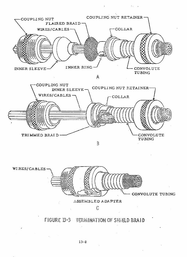
-COUPLING NUTFLAIRED BRAI D'
COUPLING NUT RETAINER
A
CONVOLUTETUBING
TRIMMED BRAI D -CONVOLUTETUBING
WI RES/ CABLES
CONVOLUTE TUBING
ASSEMBLED ADAPTER
FHGURE D-3 TERSmNATiON OF SHE LD BRAS D
13-8
SECTION 14
APPLICATION OF FIBERGLASS BRAID
14.1 GENERAL
This section establishes the requirements for the construction and
installation of fiberglass braid on Type II electrical harnesses.
14.2 PURPOSE
Fiberglass braid shall be applied for the purpose of providing additional
flammability protection on Type II wire harnesses. The fiberglass braid shall
be installed between the wire/cable bundle and the convolute tubing; or between
metallic shield braid and convolute tubing, if shielding is required.
14.3 PROCESS CONTROL REQUIREMENTS
Special consideration shall be given to the protective handling, before,
during, and after the braiding operation. The harness assembly shall be
handled carefully and properly protected with a temporary covering to preclude
any damage or deformation. In addition, the requirements, as specified below,
shall be followed.
14,3.1 PRE-PROCESS CONTROL (FIBERGLASS BRAID WITHOUT METALLIC SHIELD BRAID)
Prior to application of the fiberglass braid, verify that the harness
routing configuration is correct and acceptable, and the temporary securing
is removed or ready to be removed. Examine the outer wire/cable insulations
for cuts, nicks, abrasions, or other physical damage. Assure that the harness
assembly is free of dirt, dust, grease, or other foreign material. Verify
that all connectors are free of physical damage and/or contamination, and
covered with protective caps at all times.
14.3.2 PRE-PROCESS CONTROL ( FIBERGLASS BRAID OVER METALLIC SHIELD BRAID)
Prior to application of the fiberglass braid, verify that the harness
assembly is correctly covered with metallic shield braid, as specified in
Section 13. Assure that the surface of the harness braid is free of dirt,
grease, or other foreign material, and that there are no cuts, nicks, abrasions,
or other physical damage. Examine connectors for physical damage or contamina-
14-1
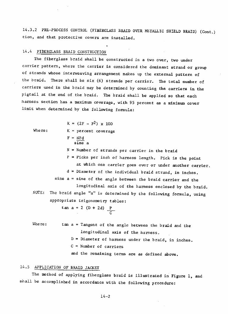
14.3.2 PRE-PROCESS CONTROL (FIBERGLASS BRAID OVER METALLIC SHIELD BRAID) (Cont.)
tion, and that protective covers are installed.
14.4 FIBERGLASS BRAID CONSTRUCTION
The fiberglass braid shall be constructed in a two over, two under
carrier pattern, where the carrier is considered the dominant strand or group
of strands whose interweaving arrangement makes up the external pattern of
the braid. There shall be six (6) strands per carrier. The total number of
carriers used in the braid may be determined by counting the carriers in the
pigtail at the end of the braid. The braid shall be applied so that each
harness section has a maximum coverage, with 95 percent as a minimum cover
limit when determined by the following formula:
K = (2F - F2 ) x 100
Where: K = percent coverage
F = NPdsine a
N = Number of strands per carrier in the braid
P = Picks per inch of harness length. Pick is the point
at which one carrier goes over or under another carrier.
d = Diameter of the individual braid strand, in inches.
sine a = sine of the angle between the braid carrier and the
longitudinal axis of the harness enclosed by the braid.
NOTE: The braid angle "a" is determined by the following formula, using
appropriate trigonometry tables:
tan a = 2 (D + 2d) PC
Where: tan a = Tangent of the angle between the braid and the
longitudinal axis of the harness.
D = Diameter of harness under the braid, in inches.
C = Number of carriers
and the remaining terms are as defined above.
14.5 APPLICATION OF BRAID JACKET
The method of applying fiberglass braid is illustrated in Figure 1, and
shall be accomplished in accordance with the following procedure:
14-2

14.5 APPLICATION OF BRAID JACKET (Continued)
a. Select the proper diameter braid jacket for the convolute tubing to
be used (reference Table 1).
b. Cut the braid jacket to the proper length as illustrated in Figure
1A. The cut braid jacket should be long enough to provide for
termination in the connector or transition adapter. Excessive
fiberglass braid can be trimmed after termination in the adapter.
c. Slide the braid jacket over the wire bundle(s), taking care not to
damage the braid, as illustrated in Figure 1B.
NOTE: Spot ties and/or lacing are to be removed immediately prior to
braid application, when applicable.
d. Select and install convolute tubing as described in Section 15,
titled "Application of Convolute Tubing".
e. Terminate braid jacket in connector and/or transition adapters as
described in paragraphs 14.6 through 14.8.
14.5.1 EXAMINATION OF APPLIED BRAIDING
Subsequent to application of braiding and prior to adapter securing,
verify that the shield braiding coverage meets or exceeds the following
requirements. The braiding operation shall show evidence of good workmanship.
Braiding strands shall be free of kinks, splits, lumps, nicks, or abrasions.
The shield braiding shall be visibly free of dirt, grease, and other foreign
materials. The braided surface in each section or branch leg shall be smooth
and continuous from start to termination of the braid. Strands in each
carrier shall not form irregular patterns. Braid shall cover the enclosed
harness so that any area where the wire/cable beneath the braid is visible
does not exceed 0.1 percent of the total surface area in one linear foot of
the harness. Braid shall not be moved aside by hand when checking such areas.
Portions of the braid that extend above the general contour of the braided
surface area are permissible provided the increase in harness diameter does not
result in a 5 percent maximum increase in the harness cross sectional area,
and the braid is unbroken.
14-3

14.6 BRAID TERMINATION ADAPTERS
The braid jacket shall be secured to connector or transition adapters
to ensure proper termination of the braid. The adapters required for termina-
tion of convolute tubing with fiberglass braid and metallic shield braid
(when applicable) consist of five major parts; the three parts required for non-
braided conduit (coupling nut, internal ring, and adapter), and two additional
parts for terminating the braid (braid sleeve and braid sleeve retaining).
Typical examples of connector and transition adapters are illustrated in
Figure 2.
14.7 TERMINATION PROCEDURE FOR HARNESSES WITH FIBERGLASS BRAID AND METALLIC
SHIELD BRAID
The fiberglass braid and metallic shield braid shall be terminated at
connector or transition adapters using manufacturer's recommended procedure
in conjunction with the following procedures and illustrations shown in
Figure 3:
a. Prepare convolute tubing by cutting to proper length and assembling
inner ring as described in Section 15, titled "Application of Convolute
Tubing".
b. The braided wire/cable bundle is inserted by pulling it through the
tubing with a tie cord; it is then expanded against the inside of
the tubing by compressing the ends of the braid.
c. Slide the coupling nut and collar over the convolute tubing and
flair both the fiberglass braid and metallic shield braid out around
the end of the tubing, as shown in Figure 3Ao
d. Insert the inner sleeve and trim the fiberglass braid and metallic
shield braid as shown in Figure 3B.
e. Slide collar and coupling nut forward and couple to the adapter as
shown in Figure 3C.
14.8 TERqINATION PROCEDURE FOR HARNESSES WITH FIBERGLASS BRAID ONLY
The braid jacket shall be terminated at connector or transition adapters
using manufacturer's recommended procedures in conjunction with the following
procedure and illustrations shown in Figure 3:
a. Prepare convolute tubing by cutting to proper length and assembling
inner ring as described in Section 15, titled "Application of Convolute
Tubing".
14-4

14.8 TERMINATION PROCEDURE FOR hkRLESSES WiTHI- FI3ERGLASS BRAID ONLY (Continued)
b. The braided wire/cable bundle is inserted by pulling it through the
tubing with a tie cord; it is then expanded against the inside of
the tubing by compressing the ends of the braid.
c. Slide the coupling nut and collar over the convolute tubing and flair
the braid out around the end of the tubing, as shown in Figure 3A.
d. Insert the inner sleeve and trim braid as shown in Figure 3B.
e. Slide collar and coupling nut forward and couple to the adapter as
shown in Figure 3C.
14.9 BRAID TERMINATION PROCESS VERIFICATION
Examine the completed adapter to assure that all applicable provisions of
this document and applicable engineering documents are complied with. Particular
care shall be exercised to assure that the assembled adapter is free of such
defects as:
a. Visible dirt, grease, or other foreign materials.
b. Adapter coupling devices that are loose, bent, or have burred or
scored coupling threads.
c. Protective finishes that are scratched, dented, or damaged so that
the base metal is exposed.
14-5
f-

04-iu)
a.NU,
rnwaJR*4- 0)A-i
0)
-rdC.)
co
*,1 .FCl)0)0-,q-4H
) ri)
14-6
E-4X
o
E- nH
-
X4 cn
O m
4
cc X
n
X E
-4
m
O
N
O
' C
) -(N
J

FIBERGLASS BRAID CUTTO PROPER LENGTH
A
-WIRE HARNESS BUNDLEOR METALLIC BRAID
B
FIGURE 14-1 FIBERGLASS BRAID APPLICATION
14-7

COUPLING NUT RETAINER
COUPLING NUT
--- INNER RING
\-INTERNAL BRAID
(FIBERGLASS ORCONVOLUTE TUBING -- METALLIC AND
FIBERGLASS)
FIGURE 1-2 TYPICAL BRAID TERMINATION ADAPTER
14-8

-COUPLING NUTFLAIRED BRAID
\ WIRES/CABLES --
COUPLING NUT RETAINER
-- COLLAR
INNER RING
A
CONVOLUTETUBING
COUPLING NUT RETAINER'
BTUBING
WI RES/ CABLES
CONVOLUTE TUBING
ASSEMBLED ADAPTER
C
FIGURE 14-3 TERMINATION OF FIBERGLASS BRAID
14-9
INNER

SECTION 15
APPLICATION OF CONVOLUTE TUBING
15.1 GENERAL
The section describes the procedures, methods, and materials used when
applying convolute tubing on wire harnesses. Type I harnesses shall have
an outer covering of fluorocarbon elastomer tubing, and type II, III, and
V harnesses shall be covered with TFE convolute tubing. All process criteria
contained in this section shall apply to both types of convolute tubing,
except where noted.
15.2 PROCESS CONTROL REQUIREMENTS
Prior to application of the convolute tubing, verify that the harness
assembly is free of dirt, d4st, grease, and other foreign material. Assure
that the outer surface of the harness insulation has not been cut, nicked, or
abraded during previous processing and/or handling. In addition, the require-
ments, as specified below, shall be followed as applicable.
15.2.1 PROCESS CONTROL - TYPE I HARNESS ASSEMBLIES
Verify that the harness layup is completed and ready for the application
of the convolute tubing. Assure that the routing configuration is correct and
that all temporary securing is ready for removal. Examine the outer surface
of the wire and cable insulation for possible damage immediately prior to the
convolute tubing application.
15.2.2 PROCESS CONTROL - TYPE II HARNESS ASSEMBLIES
Verify that the harness layup is ready for application of the tubing.
Assure that the fiberglass braid and metallic shield braid (when applicable)
are free of nicks, scrapes, broken strands, or uneven braided areas. Determine
that the braid coverage meets or exceeds the minimum allowable.
15.2.3 PROCESS CONTROL - TYPE III AND TYPE V HARNESS ASSEMBLIES
Verify that the harness layup is ready for application of the convolute
tubing. Assure that the routing configuration is correct and that all temporary
securing is ready for removal, when applicable. If the harness has been covered
15-1

15.2.3 PROCESS CONTROL - TYPE III AND TYPE V HARNESS ASSEMBLIES (Continued)
with metallic shield braid, assure that the braid is free of nicks, scrapes,
broken strands, or uneven braided areas. Determine that the braid coverage
meets or exceeds the minimum allowable of 85 percent coverage.
15.3 CONVOLUTE TUBING
The convolute tubing, sizes and types, shall conform to the applicable
engineering drawing, and to the requirements of Specification 40M51284,
entitled "Specification for Convolute Tubing". The type and size to be used
will depend upon the intended application. Assure that the selected tubing
is free of cuts, slits, or punctures that penetrate the conduit wall, prior
to application over the wires/cables.
15.3.1 CONVOLUTE TUBING PREPARATION
After the type and size of tubing has been selected, measure the net
length of tubing required. Lay and position the tubing so that the end to be
cut is lowest; this procedure will reduce the possibility of foreign material
falling into the tubing during the cutting operation. Non-reinforced tubing
shall be cut by collapsing the tubing between the fingers prior to cutting.
Trim the tubing, starting at the base of the convolute peak, as shown in
Figure 1. The cut shall be square with the axis of the tubing, and free of
ragged edges or nicks. Following the trimming operation, the interior of the
convoluted tubing shall be cleaned by blowing filtered air through the tubing.
15.3.2 CONVOLUTE TUBING APPLICATION
Prior to application of the convolute tubing over the wire/cable bundle,
verification shall be made to ensure that the outer insulation or braid, as
applicable, is clean and free of damage. After verification, apply the
convolute tubing as described in the following procedures:
a. Lay the tubing end-to-end with the wire/cable bundle.
b. Insert a leader cord into the tube and draw it through. Clean,
filtered air may be blown through the tubing to push the cord through.
A cotton ball may be tied to the end of the cord to facilitate drawing
the cord through the tubing. If necessary, attach a coated steel
leader wire to the cord and draw the wire through the tubing. This
operation will only be necessary for long runs or for large wire/
15-2
15.3.2 CONVOLUTE TUBING APPLICATION (Continued)
cable bundles.
NOTE: Ascertain that the leader wire or cord is free from protrusions
which could damage the tubing. Remove all lacing or spot ties
from the bundle immediately prior to pulling the wire through
the tubing, when applicable.
c. Prepare the end of the wire bundle by tying with a tie cord.
d. Attach the leader wire or cord to the end of the wire/cable bundle.
e. Pull the bundle through the tubing with a steady, even pull. The
leader and wire/cable bundle must be in the same plane as the tubing
during pulling.
f. Remove the leader from the bundle after the required length has been
pulled through the tubing.
15.4 CONVOLUTE TUBING TERMINATION PROCEDURES - TYPE I HARNESS ASSEMBLIES
The criteria contained in the following paragraphs establish the methods,
materials, and hardware required to assemble termination assemblies for Type I
harnesses. This criteria is applicable only to termination of fluorocarbon
elastomer, crosslinked type convolute tubing.
15.4.1 ASSEMBLY OF CONNECTOR BOOTS IN CONVOLUTE TUBING
Convoluted tubing may be attached to the connector by means of a molded
boot which is locked to the tubing by a molded adapter. The boot shall be
secured to the connector by means of a friction-retained locking ring molded
into the interior neck of the boot, and a clamp attaching around the boot and
connector backshell. Details of required adapter, boot, clamp, and assembled
components are illustrated in Figure 2. The component parts shall be attached
to the convolute tubing and connector as illustrated in Figure 2 and as described
in the following procedure:
a. After application of the convolute tubing, and prior to termination of
the wires/cables, the boot shall be installed in a retracted position
by sliding the boot away from the connector end of the harness and
over the tubing.
b. After termination of the wires/cables in the connector, slide the
boot back towards the connector until the boot contacts the connector.
Hold the connector so that strain is not placed on the wire/cable
terminations.
15-3

15.4.1 ASSEMBLY OF CONNECTOR BOOTS IN CONVOLUTE TUBING (Continued)
c. Install the adapter by expanding the adapter to fit over the convolute
and allowing it to retract in place. The locking notch is off-center
and the widest portion is orientated toward the connector end.
Three full convolutions must be fitted into the adapter and the tubing
shall be terminated against the stop on the connector end of the
adapter.
d. To assemble the boot to the connector, cock the boot at a slight
angle and push the connector back shell through the boot opening
until the boot locking ring is fitted into the space between the
connector back shell and compression ring.
e. Clamp the connector end of the boot securely over the connector back
shell.
15.4.2 ASSEMBLY OF PANEL ADAPTERS ON CONVOLUTE TUBING
Panel adapters, as illustrated in Figure 3, shall be assembled to convolute
tubing by aligning the adapter grooves to the sides of the convolute, opening
the adapter, and sliding the adapter over the convolute until it bottoms. The
longer neck portion of the adapter shall be secured to the convolute with a
clamp, as illustrated in Figure 2D.
15.4.3 ASSEMBLY OF CONNECTOR ADAPTERS ON CONVOLUTE TUBING
Convoluted tubing may be attached directly to the connector by means of
a connector adapter, as illustrated in Figure 4. Prior to termination of the
wires/cables into the connector, the component parts of the adapter shall be
assembled on the convolute tubing as described in the following procedure:
a. Slide the snap ring over the convolute tubing away from the connector
end.
b. Install ferrule into the end of the trimmed tubing.
c. Slide the adapter body over the wires/cables and against the ferrule.
d. Terminate the wires/cables in the connector.
e. After termination of the wires/cables, place the split bushing over
the tubing and squeeze into place. Make sure that the bushing is
located immediately behind the ferrule flange.
f. Insert the ferrule, split bushing, and tubing into the back of the
adapter until it bottoms.
g. Install the snap ring, using applicable pliers, into the groove
inside the adapter body.
15-4

15.4.4 VERIFICATION OF TYPE I HARNESS TERMINATION PROCEDURES
Examine the completed harness to assure that all applicable provisions
of this document and applicable engineering documents are complied with.
Particular care shall be exercised to assure that the assembled harness is
free of such defects as:
a. Visible dirt, grease, or other foreign materials.
b. Damage, i.e., cuts, holes, tears, twists, or crushing of convolute,
boots or adapters.
c. Protective finishes that are scratched, dented, or damaged so that
the base metal is exposed.
15.5 CONVOLUTE TUBING TERMINATION PROCEDURES - TYPE II, III, AND V, HARNESS
ASSEMBLIES
The criteria contained in the following paragraphs establish the methods,
materials, hardware, and tooling required to terminate convolute tubing for
Type II, III, and V harness assemblies. This criteria is applicable only to
termination of compressed or non-compressed polytetrafluoroethylene (TFE)
convolute tubing. When harnesses enclosed in TFE convolute tubing are to be
protected with fiberglass braid, or shielded with metallic braid, the procedures
defined in Section 14, titled "Application of Fiberglass Braid", or Section 13,
titled "Application of Shielded Braid", shall be followed, as applicable.
15.5.1 TOOL REQUIREMENTS
Installation tools required for termination of tubing and shield to
hardware employing shield rings are available for each convolute tubing size.
The applicable installation tool is illustrated in Figure 5. Installation
tools utilized for tubing and braid termination shall be of the correct size
to match the convolute tubing, and shall satisfy the following requirements:
a. The convolute tubing, braid, or internal ring shall not be nicked,
gouged, cut, or scraped by the tool.
b. The convolute tubing shall not be deformed by insertion of the tool,
other than the desired expansion of the tubing.
15.5.2 ASSEMBLY OF END TERMINATIONS
The typical fittings required for end termination of non-shielded or non-
braided convolute tubing consists of three major parts (grommet follower, col-
lar, and adapter) that are illustrated in Figure 6. Termination fittings for
15-5

15.5.2 ASSEMBLY OF END TERMINATIONS (Continued)
convolute harnesses enclosed in fiberglass or metallic shield braid contain
additional parts, and shall be assembled as defined in the applicable sections
of this document.
15.5.3 INSTALLATION OF INTERNAL RING
Proper securing of convolute tubing to connector or transition adapters
requires installation of an internal ring into the end of the convolute tubing
prior to assembly of the termination fitting. The internal ring shall be
installed as described in the following procedure:
a. Slide the coupling nut retainer and collar over the convolute tubing,
away from the connector end of the harness.
b. Slide the inner ring onto the installation tool, being certain that the
chamfered edge of the inner ring is pointed into the tubing and the
ring is seated against the shoulder of the tool. Thread the tool
clockwise fully into the tubing; remove by counter clockwise rotation.
When the tool is removed, the inner ring will be retained within the
tubing at the proper depth.
NOTE: To install the inner ring, it may be necessary to pre-expand
the tubing by using the burnished (smooth) end of the installa-
tion tool, threading it fully into the tubing by rotating the
tool in a clockwise direction. A counter clockwise rotation
will allow the tool to be removed.
c. Fold in the open end of the tubing. To avoid creasing or bunching
of material, the fold should be made progressively around the diameter.
d. Insert the smooth end of the installation tool into the tubing and
rotate the tool to ensure that the folded-in tubing lies snugly and
smoothly against the inner ring.
15.5.4 CONNECTOR ADAPTER ASSEMBLY
Prior to termination of the wires/cables into the connector, the adapter
assembly shall be assembled according to the following procedure:
a. Slide the coupling nut over the wires/cables so that the inner ring
butts against the shoulder of the adapter.
b. Slide the collar and coupling nut retainer against the coupling nut
and secure by screwing the coupling nut and coupling nut retainer
together.
15-6
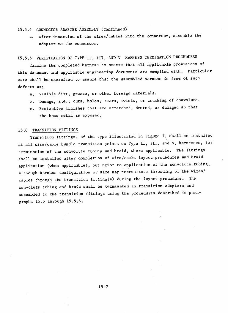
15.5.4 CONNECTOR ADAPTER ASSEMBLY (Continued)
c. After insertion of the wires/cables into the connector, assemble the
adapter to the connector.
15.5.5 VERIFICATION OF TYPE II, III, AND V HARNESS TERMINATION PROCEDURES
Examine the completed harness to assure that all applicable provisions of
this document and applicable engineering documents are complied with. Particular
care shall be exercised to assure that the assembled harness is free of such
defects as:
a. Visible dirt, grease, or other foreign materials.
b. Damage, i.e., cuts, holes, tears, twists, or crushing of convolute.
c. Protective finishes that are scratched, dented, or damaged so that
the base metal is exposed.
15.6 TRANSITION FITTINGS
Transition fittings, of the type illustrated in Figure 7, shall be installed
at all wire/cable bundle transition points on Type II, III, and V, harnesses, for
termination of the convolute tubing and braid, where applicable. The fittings
shall be installed after completion of wire/cable layout procedures and braid
application (when applicable), but prior to application of the convolute tubing,
although harness configuration or size may necessitate threading of the wires/
cables through the transition fitting(s) during the layout procedure. The
convolute tubing and braid shall be terminated in transition adapters and
assembled to the transition fittings using the procedures described in para-
graphs 15.5 through 15.5.5,
15-7

TRIMMED EDGE ---
FLUOROCARBON ELASTOMER TUBING
A
TRIMMED EDGE
POLYTETRAFLUOROETHYLENE (TFE) TUBING
B
FIGURE 15-1 TRIMMED CONVOLUTETUBING
15-8
* ,4 e-

TUBING ADAPTER
CONNECTOR BOOT CLAMP
,A
CONNECTOR BOOT
C
CLAMP-
CONNECTOR
BACKSHELL
BOOTCONVOLUTE TUBING
TUBING ADAPTERS
AS ASSEMBLED TO CONNECTOR AND TUBING
D
FIGURE 15-2 CONNECTOR BOOT ASSEMBLY-TYPE I HARNESS
15-9
B

FIGURE 15-3 PANEL ADAPTER-TYPE I HARNESS
SPLIT BUSHING
BODY
FIGURE 15-4 CONNECTOR ADAPTER-TYPE I HARNESS
15-10
TUBING
RING
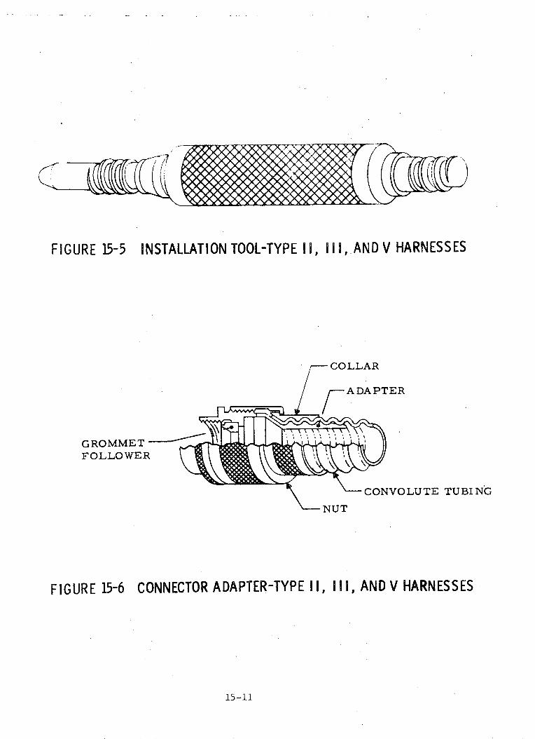
FIGURE 15-5
GROMMEFOLLOW
FIGURE 15-6
INSTALLATION TOOL-TYPE I , I II, AND V HARNESSES
COLLAR
/ ADAPTER
!.T
rER
CONVOLUTE TUBING
NCONNECTOR ADAPTER-UT
CONNECTOR ADAPTER-TYPE I, I I I, AND V HARNESSES
15-11
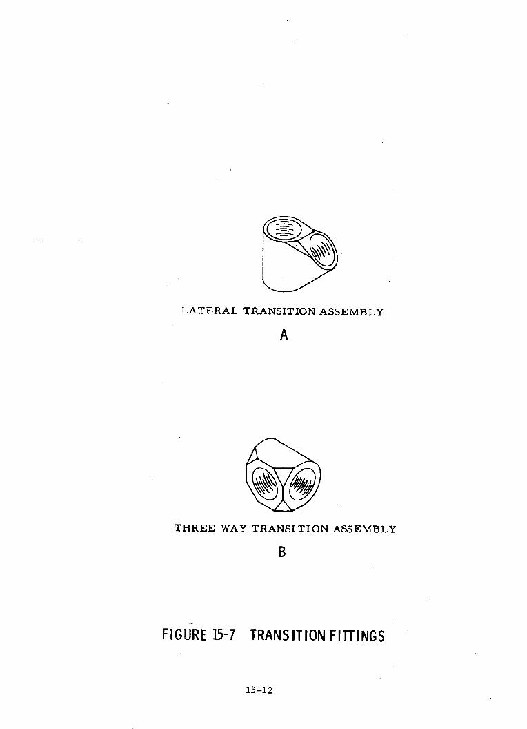
LATERAL TRANSITION ASSEMBLY
A
THREE WAY TRANSITION ASSEMBLY
B
FIGURE 15-7 TRANSITION FITTINGS
15-12

SECTION 16
HARNESS IDENTIFICATION
16.1 GENERAL
This section defines the requirements for both temporary and permanent
identification of harness assemblies and connectors, including the criteria
for temporary markings that are necessary to facilitate harness installation.
The general requirements and process controls contained in this section shall
apply to all types of harnesses enclosed in convolute tubing, except as
noted, although the identification methods shall differ for each type harness.
16.2 TEMPORARY HARNESS IDENTIFICATION
Temporary identification for scheduling and process control which is not
required for the finished assembly is permissible. Such identification markers
shall not adversely affect the assembly, and shall not appear on the completed
harness.
16.2.1 TEMPORARY IDENTIFICATION METHODS
Tagging may be used to temporarily identify harnesses, although identifi-
cation-marking-by-packaging shall be used in preference to tagging for
harnesses which can be placed in a package conveniently. When used, tags
shall be of cloth or pressed fiber, and shall be legibly marked by impression
stamping or other permanent method using characters at least 3/32 inch high.
Tags shall be securely attached to the harness with cord, or by wrap around
in a manner that will not damage the assembly in processing, shipment, or
storage. Application of adhesive tags is not recommended due to the possi-
bility of harness contamination.
16.3 PERMANENT IDENTIFICATION REQUIREMENTS
The type of permanent harness and connector identification markers used
on each type of convolute harness may differ in material composition because
of the application of the harness. Specific criteria relative to application
of marking methods and type of markers to be used are described in applicable
paragraphs of this section. Regardless of harness type or application, the
requirements established in paragraphs 16.3.1 through 16.3.6 shall apply.
16-1

1f. 3. I PRO()('E:SS CONTRO()I.
I$lforc appli-cation of the permanent harness and cuonnector identification
markings, verify that the Iharness assembly has completed the applicable
sections of this document, and design engineering requirements. Verify that
the harness configuration and temporary harness identification agree with the
design engineering drawings, and connector "P" and "J" numbers are correct.
After removal of the temporary identification markers, verify that harness
surface is not contaminated or damaged such as cuts, nicks, or abraded areas.
16.3.2 IDENTIFICATION
The combination of letters and numbers which constitute the identifica-
tion code shall be in accordance with applicable drawings, specifications,
and standards. Unless otherwise specified on the applicable drawings,
identification shall be applied directly to a piece of insulated sleeving
or a band marker, as applicable. Application of identification shall not
cause damage to the sleeve or marker, and the identification shall be applied
so that it cannot be readily rubbed off. Identification markers shall with-
stand the same temperatures and other environmental conditions to which the
harnesses are subjected.
16.3.3 HARNESS ASSEMBLY IDENTIFICATION
The harness reference designation and part number shall be stamped on a
band marker or insulated sleeve as described in the applicable procedures and
as illustrated in Figure 1. The marker or sleeve shall be placed as close
as possible to the connector strain relief clamp of the lowest alpha numbered
connector (P1 or J1) on the wire harness, but not more than 12 inches from the
connector.
16.3.4 CONNECTOR IDENTIFICATION
A band marker or insulated sleeve marked with the applicable connector
reference designation and mating part reference designation, shall be located
adjacent to each connector as illustrated in Figure 2.
16.3.5 ACCESSIBILITY
The identification shall be installed so that it is readable from the
normal point of observation. Specifically, if there is a choice of installing
16-2

16.3.5 ACCESSIBILITY (Continued)
the identification "upside down" or "right side up" from the normal point of
observation, the identification should be installed "right side up". The
. umbers may read either toward or away from the terminated end of the harness.
An objective shall be to position all identification markers on the harnesses
so as to provide maximum visibility after installation. Every effort shall
be made to locate identification so that clamps, support devices, etc., do
not have to be removed, or the harness twisted, in order to read the identi-
fication.
16.3.6 LEGIBILITY
All identification characters shall be legible, permanent, and colored
(where applicable) to contrast with the surface on which the identification
is placed. The characters shall be of sufficient size and color to provide
ease of identification through fabrication, checkout, and mission duration.
16.4 IDENTIFICATION METHODS
All harness assemblies contained in convolute tubing shall be identified
by marking identification criteria directly on metallic or non-metallic band
markers, or by means of a stamped piece of sleeving. The band marker or
sleeve material shall be capable of withstanding the same environmental con-
ditions as the harness assembly. Regardless of the method selected, an attempt
shall be made to use the same method for all identification purposes so that
uniformity can be maintained. All identification markers shall be firmly
secured to the harness so as to prevent loss of markers from shock or vibration.
16.5 METALLIC BAND MARKER IDENTIFICATION METHOD
Metallic band markers shall be marked by the method most suitable for
the material and configuration. Minimum letter and number height shall be
that which is legible without magnification and practical by the marking
method. One of the following methods shall be selected, if allowed by the
applicable specifications or engineering drawings. Regardless of the method
selected, an attempt shall be made to use the same method for all identifica-
tion purposes so that uniformity can be maintained:
a. Metal impression stamping
b. Electrochemical etching
c. Vibrating needle engraving
16-3

16.5.1 PROCESS CONTROL
Prior to marking the metallic band marker, assure that the marker is
free of grease or other foreign matter. Insure that the marking method
selected will not crack, distort, or damage the marker band. In addition,
ensure that the selected method will not cause an impression on the back side
of the marker band, whereby abrasion of the convolute tubing could occur after
installation.
16.5.2 APPLICATION
Identification shall be applied to the band markers using an approved
method which will not impair the quality of the marker band. The following
procedure shall be used:
a. Select the desired size identification plate and strap (if required)
to fit over the harness.
b, Apply the identification markings to the plate using the selected
marking method.
c. Place the plate and strap(s) around the harness and run strap through
tip of hub. The riles must be placed against the wire bundle. Pull
the strap(s) tightly around the harness by hand.
d. Tighten strap(s) using manufacturer's recommended procedure, taking
care not to compress the convolute tubing, and cut excessive strap
length.
16.6 NON-METALLIC BAND MARKER IDENTIFICATION METHOD
Identification of wire harnesses may be accomplished by affixing marked,
non-metallic band markers or identification plates imprinted with the applicable
identification data. All band markers, identification plates, and adjustable
cable straps used for identification purposes shall be per design standard
40M39582. When harness identification criteria is applied utilizing band
markers, the following procedure shall be used:
a. Select the desired size identification plate and strap (if required)
to fit over the harness.
b. Apply the identification markings to the plate using the direct
stamping application procedure described in paragraphs 16.8 through
16.8.3. Flatface type and foil must be used. More than one number,
16-4
16.6 NON-METALLIC BAND MARKER IDENTIFICATION METHOD (Continued)
or row of numbers may be stamped on a single band marker.
c. Place the plate and strap(s) around the wire bundle and run strap
tip through the hub. The ribs must be pl :cci against the wire
bundle. Pull the strap(s) tightly around the wire bundle by hand.
d. Tighten strap(s) using manufacturer's recommended tool and procedure,
taking care not to compress the convolute tubing, and cut excessive
strap length.
16.7 STAMPED INSULATION SLEEVE IDENTIFICATION METHOD
Harness identification criteria may be applied by affixing marked, non-
metallic sleeves imprinted with the applicable identification data. Sleeving
material shall withstand the same temperatures and other environmental
conditions to which the wire harness is subjected. When the harness identifi-
cation criteria is applied utilizing sleeves, the following procedure shall
be used:
a. Select the correct size sleeve to fit over the harness. Where
possible, the sleeve should be snug enough so that subsequent string
ties are unnecessary. Where it is impractical to use whole sleeves,
heat shriinkabiL or otherwi.sie, the sleeve may be split and tied at
,It c1d. I('l 'fI,'tct ;:l iccif' ' dhim aClt'[t'lc I P I)V rvide an: overLap a
distance of 1!4 the diameter.
b. Apply the identification markings to the sleeve using the direct
stamping application procedure described in paragraphs 16.8 through
16.8.3.
c. Cut the sleeving so that each length includes a complete identifi-
cation. The sleeve shall be no longer than necessary to include all
identification information plus a margin for clarity.
d. Locate the identification sleeves on the wire harness as described
for the applicable identification requirement.
16.8 MARKING OF NON-METALLIC BAND MARKERS AND SLEEVES
Band marker and sleeve identification marking shall be accomplished
with calibrated marking machines as specified in the applicable process
specification or manufacturer's instructions for detailed calibration and
operation of the machine. Marking shall be performed utilizing a marking
16-5
16.8 MARKING OF NON-METALLIC BAND MARKERS AND SLEEVES (Continued)
machine with automatic foil and work feeds (optional), adjustable tempera-
ture and thermostatically controlled marking head, with adjustable pressure
and dwell time. Marking materials (such as foils, inked ribbons, etc.)
shall be selected to correspond with the base material being identified.
16.8.1 MARKING PROCESS CONTROL
Prior to hot impression marking of the identification bands and sleeves,
assure that:
a. Band marker or sleeving is free of dust, grease, or other foreign
matter.
b. The correct size and curvature of type is selected per the manu-
facturer's instructions. Curved faced marking type shall be used
for marking sleeving, which is supported by a mandrel. Flat
faced type shall be used for marking identification plates, bands
and sleeving not supported by a mandrel.
c. Marking machine has received periodic inspection and maintenance
at intervals that will assure that the machine and accessories are
in good operating condition. Marking foil i; /hE(i ,rre.-ct ylp.
required for the type sleeving or baind mnit'r1 rlti t ,I, riar-ri.
16.8.2 APPLICATION
Identification shall be imprinted on band markers or sleeves using
an approved method which will not impair the quality of the marker or sleeve.
When the direct stamping process is used for band markers or sleeve identi-
fication, the following procedure shall be used:
a. Regulate the pressure, indicated type temperilture, ailn d el I l leI
fcr each material to provide rr,;ximnlm trtr,jffPr of pIlgIIl f,,l' F',,I
to the material being imprinted, and for best Iegl,ilI I 7. 11:X- tHc-
lowest pressure and shortest dwell time that will produce a legible
and permanent imprint, to prevent penetration of the type through
the material.
b. Use characters of sufficient size and machine adjustments necessary
to provide markings for best legibility.
c. To prevent uneven depth marking, make sure that type faces are
clean and that all characters are set in the same plane. Plated
and unplated type may be of different depths and should not be used
together.
16-6

16.9 LOCATION MARKER IDENTIFICATION
Non-metallic identification markers may be installed on the harness
assemblies to reference and identify specific locations during harness
installation. Band markers or insulated sleeves shall be stamped with appli-
cable stringer, station, frame, aximuth, grid, or plane location markings,
and located on the harness to aid in installation and configuration control.
16.10 IDENTIFICATION PROCESS VERIFICATION
Visually examine the final harness and connector identification markings
to assure that:
a. The identification marker material is of the correct type and style.
b. The identification marking agrees with applicable engineering drawing.
c. Lettering or numbering is legible.
d. Identification markers are located properly.
16-7

-CONNECTOR
/ HARNESS REFERENCEDESIGNATION
SLEEVE- "-~PART NUMBER
CONNECTORX/yS~"" " HARNESS REFERENCE
X Or n 12 INCH MAX /DESIGNATION
BAND MARKER PART NUMBER
FIGURE 16-1. iDENTIFICATION OF HARNESS ASSEMBLY
CONNECTOR REFERENCEDESI GNAT ION
6 INCH
CONNECTOR REFERENCEDESIGNATION SLEEVE
CONNECTOR REFERENCEDESIGNATION
MARKER
FIGURE 16-2' IDENTIFICATION OF CONNECTOR PLUGS
16-8
SECTION 17
HARNESS CLEANING
17.1 GENERAL
This section establishes the procedure for cleaning harness assemblies
after completion of final fabrication and test.
17.2 PROCESS CONTROL REQUIREMENTS
Prior to cleaning, assure that the harness assembly has successfully met
all previous quality and design requirements. The handling of the harness
during cleaning operations described in the following paragraphs shall be
performed with clean, lint-free gloves. In addition, verify that the facilities
environmental controls are within requirements stated in the following para-
graphs, prior to start of cleaning.
17.2.1 FACILITY REQUIREMENTS
Final harness cleaning and sealing shall be accomplished in a class 100,000
level clean room that complies with the intent of MSFC-STD-246A. The temperature
shall be +680 F to +78°F, and relative humidity shall be 60%, or less, if
necessary to preclude condensate forming. The garment requirements shall be
coveralls, caps, and shoe covers. Records shall be maintained of the facilities
environmental levels, with daily checks of temperature and humidity, and a
minimum of three times a week for airborne particulate. Daily checks shall be
accomplished to assure positive pressure differential and air flow of at least
40 FPM.
17.3 CLEANING OF HARNESS ASSEMBLIES
Completed harness assemblies shall be cleaned with either isoprophyl
alcohol (FED-SPEC-TT-I-735, Grade A) or ethyl alcohol (FED-SPEC-0-EO-760) to
remove all contamination and foreign matter. The cleaned harness shall be
examined under white light and black (ultra-violet) light for compliance to
the following. Visual examination shall be limited to those surfaces which are
accessible.
CAUTION: Use of other than the above cleaning agents may result in
degradation to the connector materials and possible damage to
the insulation.17-1
17.3.1 VISIBLY CLEAN (WHITE LIGHT)
Visibly clean shall be construed to mean the freedom of surface contamina-
tion such as scale, dust, dirt, corrosion, and other foreign particulate
matter, including grease, oil, or other forms of volatile contamination. Scale-
free discoloration and specific surface treatments shall not be considered
visual contamination.
17.3.2 BLACK LIGHT (ULTRAVIOLET)
When viewing harnesses under black light, any evidence of foreign fluoresent
matter on the harness or connector surfaces shall be cause for recleaning.
17.3.3 CLEANING OF CONNECTORS
Prior to the final installation of the protective connector covers, the
interior and exterior of each connector shall be examined under both white
and black light to verify freedom from grease, finger prints, or oily substances.
Particles of dust or dirt, which are observed, shall be removed by use of a
vacuum.
17-2

SECTION 18
HARNESS HANIDLING, PACKAGING AND :;EALING
18.1 GENERAL
This section establishes and defines the methods and requirements for
handling, protection, and sealing of harness assemblies.
18.2 PROTECTION LEVEL CRITERIA
Electrical harness assemblies require varying degrees of protection at
all times. The performance and/or reliability of a harness assembly can be
directly affected by the lack of adequate packaging or protection during
in-process handling, storage, and shipment. Harness assembly protection shall
be considered as the application of protective measures to prevent damage from
physical and climatic environments during intra/inter facility handling, in-
process, transportation, and storage operations.
18.3 APPLICATION
The appropriate level of harness protection shall be implemented by the
manufacturing planning documents, and shall provide the necessary information
required to assure adequate protection from the initial processing of the wire
and cable, through shipment of the finished harness assembly.
18.4 IN-PROCESS HARNESS ASSEMBLY HANDLING PROTECTION
Harness handling shall be done carefully and held to a minimum to reduce
the possibility of connector damage and work-hardening, or fatigue of the wiring.
All connectors shall be protected with suitable snug-fitting plastic or metallic
dust caps, except when it is necessary to work directly upon them, or when
mated. Terminations and/or wire ends shall be protected singularly in a nylon
bag and secured. Harnesses with exposed metallic armor braiding shall be
protected with a suitable outer covering to preclude damage to the shield
strands (Reference paragraph 18.6). Care is required in handling harness
assemblies which have been cleaned and packaged to prevent damage or rupture
of the outer wrap or packaging.
18-1

18.4.1 INTRA-INTER PLANT PROTECTION
Whenever harnesses are required to be transported to a service or repair
area, they shall be packaged for shipment so that the harness does not become
damaged. Connectors shall be individually wrapped with nylon bags and cushion
material to prevent damage to themselves or other parts of the harness.
18.5 FINAL HARNESS ASSEMBLY SEALING AND PACKAGING
Prior to the sealing of the completed and cleaned harness assembly, assure
that all design criteria and cleaning requirements have been performed and are
acceptable. Verify that each connector is protected with a plastic or metallic
cap and over-wrapped with a nylon bag.
10TC1 A l f LA C
Coil the harness assembly (if necessary) to form a minimum loop of at
least twenty (20) times the diameter of the main harness trunk. Assure that
connectors are adequately protected and cannot damage harness wire insulation
or convolute tubing. Additional cushion material may be installed at this time.
Place the harness into a clean nylon bag and purge with dry nitrogen (MIL-P-
27401, Type 1), and immediately heat seal; then overbag with antistatic poly-
ethylene film, 6 mils thick and heat seal. Identify the sealed harness per
paragraph 18.5.4.
18.5.2 HARNESS ASSEMBLY PACKAGING
Prior to packaging, assure that the sealed harness assembly wrapping is
free of pin holes, tears, or cuts, loose or damaged closures, or broken
cleanliness certification decals.
18.5.3 PROTECTIVE CONTAINERS
The harness shall be placed into a suitably sized cushioned container.
The container construction and material shall be of such integrity to provide
positive protection from physical and climatic environments during storage and
transportation. The container size shall be selected so that the harness
generally fills the container, but does not interfere with closing of the
container. Additional cushion material may be added to firmly hold the
harness and prevent excessive movement.
18-2
18.5.4 IDENTIFICATION
Each cleaned and bagged harness assembly and container shall have an
identification label or tag attached to the sealed harness (may be inserted
between the nylon and polyethylene bag) and attached to the outside of the
container, or inserted in the container, if the label or tag can be viewed
from the outside. The tag or card shall carry the following information:
Drawing/Part Number
E.O.
Serial Number
Inspected by_
Contract Number
"This harness assembly has been cleaned in accordance
with Section 17, "Harness Cleaning".
18.6 PROTECTION OF METALLIC ARMOR BRAID
Following application of metallic woven braid, the harness assembly shall
be handled carefully and properly protected to preclude any damage or deformity
such as cuts, dents, or abrasions, to the armor braid strands. This protective
covering shall be installed at completion of armor braiding and remain on the
harness until convolute tubing is applied. The protective covering will be
so constructed to require a minimum of effort for installation and removal,
and be a material compatible with the cleaning requirements established in
Section 17 of this document.
18-3

SECTION 19
HARNESS INSTALLATION
19.1 GENERAL
This section establishes the installation criteria that pertains to
Type I (Enclosed in fluorocarbon elastomer convolute tubing), Type II
(Enclosed in TFE convolute tubing lined with fiberglass braid), Type III
(Enclosed in TFE convolute tubing, and Type V (Combination of Type III and
Type IV - Open bundle), interconnecting wire harnesses.
19.2 APPLICATION
The interconnecting wire harness types covered in the document shall
be applicable to the following areas and requirements:
a. Types I and II - Type I and Type II harnesses may be used in all
areas within the crew compartment area. These harnesses meet the
Type I flammability requirements of MSFC-SPEC-101, the outgassing
requirements of Specification 40i51264, and do not emit noxious
gases. Operating temperature ranges are as follows: Type I - 0 to
plus 660 C, Type II - minus 73 to plus 2600 C.
b. Type III - This type harness may be used in all areas outside the
crew compartment area, including the engine compartment, where
abrasion protection is required and so routed that it does not come
in contact with localized flame or hot gas impingement.
c. Type V - This type harness is a combination of Type III and Type IV
harnesses and may be used in all areas outside the crew compartment,
including the engine compartment, where it shall not be subjected to
localized flame, or hot gas impingement. The open bundle (Type IV)
portion of the harness shall not be installed .in areas where it
shall be subjected to abrasion. Installation of the open bundle
portion(s) of Type V harness shall be performed using the criteria
established in Volume II, entitled "Manufacture and Quality Control
of Type IV - Open Bundle Interconnecting Wire Harnesses".
19-1
19.3 PROCESS CONTROL REQUIREMENTS
Prior to installation of the completed harness assembly, verify that the
harness has satisfactorily complied with all applicable processes, controls,
and requirements of this document and applicable engineering design drawings.
Assure that the harness has successfully passed functional testing and has
been cleaned in accordance with Section 17 of this document. Special care
shall be taken to assure that the harness packaging is free of physical or
environmental damage, and identified in accordance with Section 18. Verify
that the harness assembly is adequately protected from physical damage or
contamination at all times, during and after installation by application of
temporary protective outer coverings, as described in paragraph 18.6. Before
routing the harness assembly, verify that the area is ready for the harness,
and that all sharp edges, protrusions, or structural members are covered with
protective material as specified in the following paragraphs.
19.3.1 SAFETY
The applicability of safety measures and the required scope of compliance
shall be determined by the Safety Representative. Care shall be exercised
during the performance of the installation requirements of this document. Good
workmanship practices are essential to the safety of personnel installing the
finished product, and to the equipment in which the wire harness may be an
integral part.
19.3.2 FACILITIES
All wire harnesses shall be unpackaged and installed in a clean area.
The general working area shall be maintained in a clean and orderly condition
at all times. Only tools, fixtures, test equipment, etc., which are required
to perform the task shall be allowed in the area.
19.4 HARNESS PROTECTION
Where wire harnesses pass near sharp or abrasive surfaces and may come
in contact with the surfaces due to stresses during handling or flight, the
harness shall be suitably protected to avoid any damage. The convoluted
tubing used for Type I, II, III, and V harnesses provides protection from
abrasion, but additional protective requirements may be necessary to ensure
systems integrity. The following paragraphs establish criteria for deter-
mining additional harness protection requirements, and provide techniques
19-2
19.4 HARNESS PROTECTION (Continued)
for eliminating potential damage conditions.
19.4.1 PROTECTIVE DEVICE REQUIREMENTS
A complete visuai inspection shall be made of all surfaces coming into
contact with wire harnesses to verify that no sharp or rough edges exist.
Protective devices, in addition to the convolute tubing, shall be installed
to provide permanent harness protection from abrasion or other damage.
Protection shall be installed where harnesses are routed across protruding
or sharp edges of structures; through or across unprotected holes or cutouts;
where tubing can contact protruding rivets or other fasteners; and at any
location where the danger of chafing the harness exists. Particular attention
shall be given to harness slack in this respect.
19.4.2 CHAFING
Wire harnesses must be protected against damage that may result from
rubbing against a surface or edge, or against any other object. Locations of
possible abrasion damage (chafing) to the harnesses are as follows:
a. Where a harness passes around a corner or a shelf, bracket, equipment,
or structure.
b. Where a harness passes through a hole, and a cushioned clamp or
grommet alone is not adequate.
c. Where a harness is exposed to excessive contact by personnel or equipment.
d. Where harnesses pass near sharp edges of bolts, nuts, or rivets.
19.4.3 HARNESSES ON OR NEAR MOVING PARTS
Harnesses that are attached to assemblies where relative movement occurs,
or near rotating parts, shall be installed and protected in such a manner
as to prevent damage caused by movement. This deterioration includes abrasion
caused by one harness rubbing against another or by twisting and bending.
Wire harnesses should be rerouted or protective devices shall be installed to
provide permanent wire protection from abrasion and/or other damage. Harnesses
shall be installed to twist instead of bend across hinges, although bending
of harnesses at gimbal locations is acceptable.
19-3

19.4.4 PROTECTIVE GROMMETS
Where harnesses are routed over, or may contact any protrusions or
sharp edges, protection of the harnesses will be provided by covering the
protrusion or sharp edge with Teflon cushion or equivalent material. Where
harnesses are routed over or through structural members that have Teflon
caterpillar-type grommets, rigid grommets, or any protrusions and sharp edges,
the harness should be supported by clamping to prevent the possibility of
chafing. Figures 1 and 2 illustrate typical installations where grommet
protection would be applied. When necessary to trim grommets to obtain
proper fit, the gap after installation shall not exceed 1/10 inch. The angle
of the cut shall be 45 degrees to the axis of the wire harness.
19.4.5 PROTECTIVE CLAMPING
Approved clamps shall be used to maintain the separation between any
surface and the wire harness assembly. Harnesses shall be prevented from
moving inside the clamp by selecting the proper clamp size and installing it
with adequate tightness (see Section 20, "Support and Clamping"). Clamps used
to support and separate harnesses from adjacent surfaces shall be attached to
structure for support whenever possible. If supporting structure is not
available, the clamps may be attached to lines carrying inert fluids such as
water, helium, or nitrogen. (For lines carrying flammable fluids, see
paragraph 19.5.2.) If the clamps are attached to the lines carrying inert
fluids, the clamps shall be located close to those clamps which support the
line itself. Where possible, wires and cables shall not depend on insulating
tubing to maintain a separation from any adjacent surface; except that
insulating tubing shall enclose the wires and cables when they lie on the
inner surface of metallic conduit.
19.5 HARNESS INSTALLATION
Where possible, all wire harnesses shall be installed in the form of
quickly removable and replaceable harnesses, attachable to and detachable
from the adjacent harnesses, regardless of function, location, or form of
electrical connection. All harnesses shall be installed so that installation
or removal of equipment is permitted. Wire harnesses shall not be pulled to
facilitate installation, nor to secure additional slack. Any visible evidence
of damage to the harness is cause for rejection.
19-4

19.5.1 ROUTING
All electrical wire harnesses shall be routed to avoid abrasion, cutting,
or piercing of the outer insulation by contact with rough surfaces, sharp
edges, or shockmounted equipment. Harness assemblies clamped to the structure
shall be routed as directly as possible (insofar as practical harness assemblies
shall be mounted parallel and/or perpendicular) and shall be protected along
traffic lanes and near entrance areas where the harness is susceptible to use
as handholds, steps, or other misuse. Wire harnesses may contact other
harnesses provided they are suitably attached and routed to:
a. Provide accessibility for inspection and maintenance.
b. Prevent harness deterioration from high temperature or
cold temperature extremes.
c. Minimize possibility of damage.
d. Minimize the need for protective materials.
19.5.2 ROUTING NEAR FLAMMABLE FLUID LINES
A separation of 2 inches shall be maintained between harnesses and lines
carrying flammable fluids. Where barriers exist that preclude contact between
harnesses and fluid lines, the requirements for separation and mounting shall
not apply. Clamping and securing of harnesses to a pressure or flammable
fluid line shall not be permitted, although where necessary due to structural
characteristics, harnesses in engine areas may be clamped to a flammable
fluid line for separation only (2 inches between). Reference Figure 3.
19.5.3 ROUTING NEAR NON-FLAMMABLE FLUID LINES
Where necessary due to structural characteristics, harness assemblies may
be clamped to a nonflammable fluid line for separation. Installations shall
be separated from nonflammable fluid lines by a minimum of 1/2 inch. Reference
Figure 3.
19.5.4 IMPROPER CONNECTIONS
Where similar connectors are used in adjacent locations, wire harnesses
should be so routed and supported that improper connections cannot be made.
When this requirement cannot be accomplished by routing, special markings or
identification shall be provided to highlight proper connections.
19-5

19.5.5 DIRECTION OF BREAKOUTS
When breakouts of harnesses are made at a support clamp, they will, where
possible, be made in a direction away from the clamp-cushion wedge or clamp-
mounting screw. If the harness must break out in both directions, care shall
be taken to ensure that the convolute tubing will not be damaged by the
metallic portions of the clamp.
19.5.6 BEND RADIUS
The minimum radius of bend for harness installation shall not cause
Convolute deformation nor affect normal harness life or characteristics. The
harness bend radius is measured as shown in Figures 4 and 5, and shall conform
to the minimum bend requirements established in Tables 1, 2, and 3, as
applicable.
19.5.7 SLACK
Slack in harnesses between clamp installations shall be provided to
avoid strain on wires/cables in the harness or connections. Slack shall be
minimized in order to achieve a neat and orderly appearance of the installations,
but sufficient slack shall be provided for the following purposes:
a. To permit ease of maintenance, including connector coupling and
uncoupling.
b. To prevent mechanical strain on wires or cables, convolute tubing,
junctions, and harness supports.
c. To permit movement of shock-and-vibration-isolated equipment.
19.5.8 SLACK CONDITIONS
Slack shall not be so great that the harness, under its own weight, or
under acceleration or vibration loads, contacts sharp or rough objects that
might damage the harness. Movement of the harness by hand shall not cause
the harness to touch any adjacent surface. Movement by hand is defined as
applying sufficient forces to move the harness without visibly distorting or
moving the mounting clamps, or causing the harness to slide within the clamps.
A 1/2 inch distance shall be maintained between the harness and any adjoining
structure. If the slack permits the harness to come within 1/4 inch of a
sharp or rough object which could cause damage, one or more of the following
shall be accomplished:
a. Reduce slack
19-6

19.5.8 SLACK CONDITIONS (Continued)
b. Increse the distance from object
c. Add additional[ support
d. Add adequate protection to the harness and to the sharp or rough
object to adequately protect the harness fri.i damage.
13.6 INSPECTION REQUIREMENTS FOR HARNESS INSTALLATION
Harness installation integrity shall be in compliance with all provisions
of this document. Particular care shall be exercis:ed to ensure such compliance
prior to closeout of areas or where subsequent installations make inspection
difficult.
CAUTION: Inspections performed to verify integrity of installation
shall be accomplished by visual examination. Handling or
movement of harnesses shall be minimized. Due care must be
exercised to avoid possible damage to a critical installation.
19-7
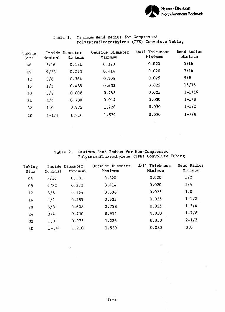
Space Division%North American Rockwell
Table 1. Minimum Bend Radius for CompressedPolytetrafluorethylene (TFE) Convolute Tubing
TubingSize
06
09
12
16
20
24
32
InsideNominal
3/16
9/23
3/8
1/2
5/8
3/4
1.0
40 1-1/4
DiameterMinimum
0.181
0.273
0.364
0.485
0.608
0.730
0.975
1.210
Outside DiameterMaximum
0.320
0.414
0.508
0.633
0.758
0.914
1.226
1.539
Wall ThicknessMinimum
0.020
0.020
0.025
0.025
0.025
0.030
0.030
0.030
Bend RadiusMinimum
5/16
7/16
5/8
15/16
1-1/16
1-1/8
1-1/2
1-7/8
Table 2. Minimum Bend Radius for Non-CompressedPolytetrafluorethylene (TFE) Convolute Tubing
DiameterMinimum
0.181
0.273
0.364
0.485
0.608
0.730
0.975
1.210
Outside Diameter Wall Thickness Bend RadiusMaximum Minimum Minimum
0.320 0.020 1/2
0.414 0.020 3/4
0.508 0.025 1.0
0.633 0.025 1-1/2
0.758 0.025 1-3/4
0.914 0.030 1-7/8
1.226 0.030 2-1/2
1.539 0.030 3.0
19-8
TubingSize
06
09
12
16
20
24
32
40
InsideNominal
3/16
9/32
3/8
1/2
5/8
3/4
1.0
1-1/4

|& Space DivisionBy North American Rockwell
Table 3. Minimum Bend Radius for Fluoro-carbonElastomer, Crosslinked Convolute Tubing
Diame terMinimumA
0.22
0.30
0.36
0.40
0.50
0.63
0.75
0.87
1.10
Outside DiameterMaximum
B
0.42
0.52
0.60
0.65
0.77
0.94
1.10
1.25
1.50
Wall ThicknessMinimum
C
0.030
0.030
0.030
0.030
0.030
0.030
0.030
0.030
0.030
Bend RadiusMinimum
R
0.40
0.90
1.95
2.60
3.25
4.15
4.95
5.85
6.50
19-9
TubingSize
06
09
12
14
16
20
24
28
36
InsideNominalA
3/16
9/32
3/8
7/16
1/2
5/8
3/4
7/8
1 3/32

I1CATERPILLAR GROMMETS
FIGURE 19-1 INSTALLATION OF CATERPILLAR GROMMETS
- SPLIT CABLE GROMMET
FIGURE 19-2 INSTALLATION OF SPLIT CABLE GROMMETS
19-10

STRUCTURE
FLAMMABLE FLUID
CARRYING LINE
CLAMP --
-CLAMPS TO PROVIDEADEQUATE SEPARATION
2 INCH (MINIMUM)
FLAMMABLE LINES
1/2 INCH (MINIMUM)NON-FLAMMABLE LINES
HARNESS ASSEMBLY
PRIMARY SUPPORT
FIGURE 19-3 SEPARATION OF V;'IRE HARNESSES FROM FLUID LINES
19-11

L-WALL THICKNESS
INSIDE DIAMETER
OUTSIDE DIAMETER
(R) MINIMUM BEND RADIUS-
FiGURE 19=4 'MINIMUM BEND RADIUS FOR COMPRESSED ANDNON-COMPRESSED POLYTETRAFLUORETHLENE (TFE) CONVOLUTE TUBING
L WALL THICKNESS
-I NSIDE DIAMETER
OUTSIDE DIAMETER
(R) MINIMUM BEND RADIUS -
FIGURE 19-5 MINIMUM BEND RADIUS FOR FLUOROCARBONELASTOMER, CROSSLINKED CONVOLUTE TUB ING
19-12

SECTION 20
SUPPORT AND CLAMPING
20.1 GENERAL
The primary purpose of clamps is to secure and support the wire harness.
These clamps are also utilized to reduce or eliminate vibration, to maintain
clearance, and to relieve strain on wire/cable terminating devices, shock/
vibration mounts and other equipment. This section contains criteria
relative to proper clamping techniques.
20.2 REQUIREMENTS
The standards, specifications, and engineering drawings that apply to
installation of wire harnesses shall include the clamping requirements for
proper harness support. When installing wire harnesses, utilizing approved
clamping devices, the following criteria shall be considered:
a. Prevention of chafing and migration within the support clamp.
b. Provision of clearance when harnesses are routed through or
adjacent to bulkheads or structural members.
c. Maintenance of proper grouping during routing.
d. Prevention of mechanical strain that would break wiring, cables,
or connections.
e. Prevention of excessive movement under vibration.
f. Permit free movement of shock/vibration - mounted equipment.
g. Prevention of interference between harnesses and other equipment.
20.2.1 TEMPORARY SUPPORT PROVISIONS
All wire harnesses shall be adequately supported during installation to
prevent damage due to excessive bending, kinking, or strain. Such supports
shall be of a type which will not cause cold flow of wire insulation, or
deformation of the convolute tubing. Temporary supports for harness connec-
tions shall not cause distortion of the wire entry holes in the rear face of
the environmental sealing grommet or otherwise result in deterioration of the
environmental seal.
20-1

20.3 CLAMPING DEVICES
In the fabrication and installation of harnesses, positive locking clamps
shall be used for harness support. Clamping devices shall be of suitable
size and type to hold the convolute tubing firmly without damage after fastening
and without changing the cross-sectional shape of the tubing.
20.3.1 CLAMP TYPE SELECTION
Wire harnesses shall be supported by clamps as specified on the applicable
installation drawing. To insure proper fit, it is recommended that provisions
be made to allow deviation of clamp sizes larger or smaller than specified on
the installation drawing. Loop type clamps, as illustrated in Figure 1, shall
be used on harnesses. In addition, the following criteria shall be used in
selecting clamps;
a. The size of the clamp shall permit the mounting tabs of the
clamping device to meet without deforming the convolute tubing.
b. Washers or other spacer devices shall not be installed between
the mounting tabs of the clamping device to obtain proper fit.
c. Deformation of the clamp shall be cause for rejection.
d. Clamps shall be of sufficient size that the harness is held firmly
without the need of wrapped sleeving or tape, or the use of filler
materials.
e. Clamp size shall be adequate to hold the harness securely in position
without being pinched, deformed, or damaged.
f. Clamping device shall have sufficient grip to prevent sliding or
twisting of the wire harness inside the clamp after tightening
to the point of gap closure between mounting tabs.
20.4 CLAMP AND SUPPORT INSTALLATION
Harness assemblies supported by clamps shall be secured to the vehicle
structure. When harnesses are routed over or through structural members that
have grommets, or any other protrusions and sharp edges, the harness shall be
supported by clamping to prevent the possibility of chafing. Where necessary,
due to structural characteristics, harness assemblies may be clamped to
harnesses or nonflammable fluid lines for separation (minimum of 1/2 inch
between). Clamping and securing of harnesses to pressure or flammable fluid
lines shall not be permitted.
20-2

FORWARD EDGE OF WEDGE (PLASTICCLAMP) OR FORWARD EDGE OF MET-AL CLAMP PULLED IN SLIGHTLYTOWARD CENTER OF CLAMP.
` R |CWEDGE CS
CLAMP CLOSES.WITH NO GAP
FIGURE 20-2 ACCEPTABLE CLAMP INSTALLATION
4 -CLAMP IS NOT CLOSED
CONVOLUTE TUBING ISBETWEEN THE CLAMP
BEND AT THIS POINT ISNOT ACCEPTABLE.( METAL CLAMP ONLY)
PROPERLY.PINCHED
OPENI NG.
CLAMP DEFORMATION ISCAUSE FOR REJECTION,(METAL CLAMP ONLY)
FIGURE 20-3 UNACCEPTABLE CLAMP INSTALLATION
20-3

SECIION 21
CONNECTOR MATING
21.1 GENERAL
This section establishes the standard processes related to mating of
electrical connectors. The criteria contained in the following paragraphs
shall apply to all types of connectors, except where noted.
21.2 PROCESS CONTROL REQUIREMENTS
Immediately prior to mating, visually examine each connector to ensure
that:
a. The insert faces are clean and free of chips, dirt, or any foreign
materials that would damage the pins, or that would prevent them
from easily entering the socket.
b. There are no bent, damaged, or misaligned pins or sockets or any
splits, cuts, gouges, or other damage to the grommets.
c. The pins or sockets are not abnormally recessed or extended.
d. There are no nicks or fractures in the connector shell or inserts.
e. The plating is free of flaking, porosity, roughness, or non-adhesion.
f. Connectors with removable "o" ring seals or grommets are properly
installed in the connector halves prior to mating.
g. Connectors are properly marked so that "P" and "J" numbers match,
and pin and socket configurations are compatible.
2L2.1 CONNECTOR PROTECTION
All connectors shall have protective caps installed throughout all stages
of fabrication and installation, except when mated. The caps shall provide
both environmental and physical protection.
NOTE: Protective caps on the connectors may be removed during the
visual examination, but must be re-installed and remain in
place until the connectors are ready to be coupled.
2L2.2 PRECAUTIONARY PROCEDURES
Caution shall be exercised when mating connectors to ensure that damage
does not occur to connector pins or sockets. Under no conditions shall
21-1
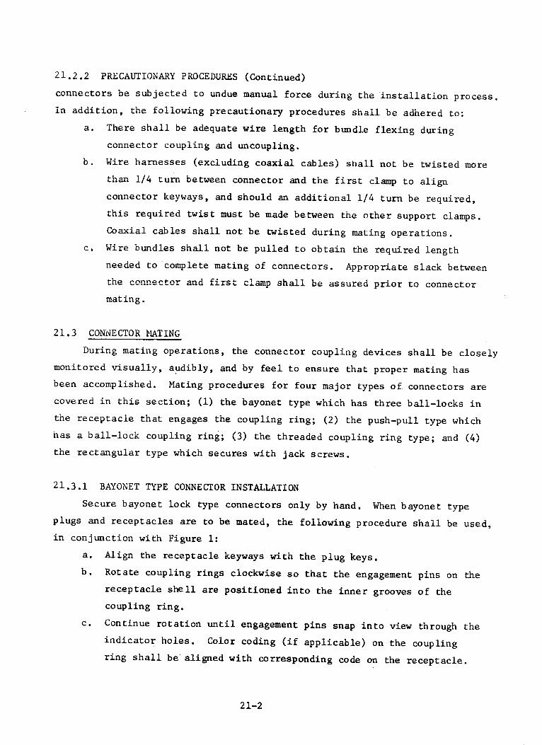
21.2.2 PRECAUTIONARY PROCEDURES (Continued)
connectors be subjected to undue manual force during the installation process.
In addition, the following precautionary procedures shall be adhered to:
a. There shall be adequate wire length for bundle flexing during
connector coupling and uncoupling.
b. Wire harnesses (excluding coaxial cables) shall not be twisted more
than 1/4 turn between connector and the first clamp to align
connector keyways, and should an additional 1/4 turn be required,
this required twist must be made between the other support clamps.
Coaxial cables shall not be twisted during mating operations.
c. Wire bundles shall not be pulled to obtain the required length
needed to complete mating of connectors. Appropriate slack between
the connector and first clamp shall be assured prior to connector
mating.
21.3 CONNECTOR MATING
During mating operations, the connector coupling devices shall be closely
monitored visually, audibly, and by feel to ensure that proper mating has
been accomplished. Mating procedures for four major types of connectors are
covered in this section; (1) the bayonet type which has three ball-locks in
the receptacle that engages the coupling ring; (2) the push-pull type which
has a ball-lock coupling ring; (3) the threaded coupling ring type; and (4)
the rectangular type which secures with jack screws.
21.3.1 BAYONET TYPE CONNECTOR INSTALLATION
Secure bayonet lock type connectors only by hand. When bayonet type
plugs and receptacles are to be mated, the following procedure shall be used,
in conjunction with Figure 1:
a. Align the receptacle keyways with the plug keys.
b. Rotate coupling rings clockwise so that the engagement pins on the
receptacle shell are positioned into the inner grooves of the
coupling ring.
c. Continue rotation until engagement pins snap into view through the
indicator holes. Color coding (if applicable) on the coupling
ring shall be aligned with corresponding code on the receptacle.
21-2

21.3.2 PUSH-PULL TYPE CONNECTOR INSTALLATION
When push-pull type plugs and receptacles are to be mated, align the
key-way on the plug with the key on the receptacle. Push forward, exposing
the colored ring which indicates engagement. (Reference Figure 2.)
21.3.3 THREADED COUPLING TYPE CONNECTOR INSTALLATION
The threaded type connector employs a single key-slot in the receptacle
and a corresponding key in the plug to ensure proper plug to receptacle
orientation prior to engagement of the threaded coupling ring. Connector
clocking is accomplished by the position of the insert within the connector
shell (Reference Figure 3). Following alignment of the connector key, the
connector shall be tightened as described in paragraph 21.4.
21.3.4 RECTANGULAR TYPE CONNECTOR INSTALLATION
Electrical rectangular connectors shall be carefully mated and unmated
in accordance with the following:
a. Place the mating connector carefully in position by aligning the
polarizing keys (posts) with the mating key slots and align the
jack screws with the threaded bore in the coupling side. Do not
rock plug side to side during mating or unmating.
b. Tighten the jack screws alternately until each jack screw is
bottomed on the coupling. Turn each jack screw no more than 2
turns each, alternately. Unequal tightening of the jack screws
will result in damage to the connector or contacts.
c. Torque each jack screw to the required level.
d. Safety wire jack screws to connector flange in accordance with
MS33540. The safety wire shall be installed such that the wire
insulation in each connector will not be touched or possibly damaged
by the safety wire.
21.4 TIGHTENING CONNECTORS
Connectors with threaded couplings shall be tightened, as far as travel
permits, by hand to permit proper alignment and prevent damage to threads.
Torquing shall then be accomplished if required. Jam nuts of jam nut type
receptacles shall be torqued in accordance with Table 1. The coupling nut
of screw type connector shall meet the requirements of Table 2.
21-3
21.5 SAFETY WIRING
Safety wire shall be applied so that the connector will not loosen.
To achieve a pulling effect, the safety wire shall not be in-line with the
center of either connector, but shall be pulling in a tightening direction
with respect to the two points where the wire is fastened. Refer to Figures
4 through 8, for illustrations of acceptable, typical safety wiring methods.
The safety wire shall be installed with the double twist method and shall
have 6-14 twists per lineal inch. The tag ends of the wire shall have 3 to 6
twists and shall be neatly trimmed to a length of approximately 1/2 inch.
The tag ends shall be bent back against the connector to avoid snagging or
scratching any object. The final installation of safety wire shall be correctly
positioned with sufficient tension so that the wire cannot be moved or slid in
any direction which could permit the threaded parts of the connector to loosen.
The wire shall have the shortest possible length. Various acceptable methods
for installing safety wire on connectors are shown in figures 4 through 8.
21,6 QUALITY CONTROL SEALING
Quality control seals shall be installed after the connector has been
mated, torqued, and safety wired (if required) according to the applicable
drawings. Quality control seals will be installed in such a manner that the
coupling ring cannot be disengaged without breaking the seal. Connectors
with broken seals shall be subjected to a thorough reinspection to assure
connector integrity, and then resealed. The seals and the environment in
which they are used shall be compatible.
21-4

Table 21.1. Jam Nut Torque Values
ConnectorShell Size
810121416182022243640
I .
. ._ I
Torque, Foot-Pounds
Minimum
2.22.73.64.55.46.37.28.19.0
13.515.3
Maximum
2.53.04.05.06.07.08.09.0
10.015.017.0
Table 21.2. Coupling Nut (Screw Type Connector)
21-5
Tnrn, F.nn.t-..PnlneConnector u, ZVU-Shell Size Minimum Maximum
10 2.2 2.514 3.6 4.020 6.3 7.024 8.1 9.028 9.9 11.032 11.7 13.040 15.3 17.0
I - --- - - - - .
C -- _ _~~~~~~~~~~~~~~~~~~~~~~~~~~~~~~~ -~~~~~~

COLOR STRIPING
CONTACTS (PIN OR SOCKET)
BAYONET ENGAGING PINS
FIGURE 21-1 BAYONET COUPLING
-MASTER KEY WAYS
rCOLOR STRIPING
CONTACTS (PIN OR SOCKET)
FIGURE 21-2 PUSH-PULL COUPLING
21-6
- -~~~~~~~~~_

-CONTACTS (PIN CR SOCKET)
-MASTER KEYWAYS
FIGURE 21-3 THREADED COUPLING
-JAM NUT
FIGURE 21-4 SAFETY WIRE ON A JAM NUT
CONNECTORSAFETY WIRE
SAFETY WIRE
FIGURE 21-5, TYPICAL SAFETY WIRING INSTALLATION
21-7
�

SAFETY WIRE
FIGURE 21-6 TYPICAL SAFETY WIRING INSTALLATION FOR TWO CONNECTORS
CONNECTOR
CONNECTOR
SAFETY WIRE
CONNECTORSAFETY WIRE
FIGURE 21-7 TYPICAL SAFETY WIRING INSTALLATION
FETY WVIRE
21-8
_I

(A) NO LOCK WIRE HOLE ON ELBOW
(B) LOCK WIRE HOLE ON ELBOW
FIGURE 21-8 TYPICAL SAFETY WIRING INSTALLATION FOR ELBOW CONNECTORS
21-9

SECTION 22
TEST
22.1 GENERAL
This section establishes the requirements for performing continuity,
insulation resistance, and dielectric withstanding voltage tests of
electrical harness assemblies. Acceptable harness continuity will be
assured by determining that the cable conductor resistance is less than the
specified maximum value. Acceptable insulation resistance will be assured
by determining that the wire insulation resistance is higher than the
specified minimum value. Performance of the dielectric withstanding
voltage test will assure that the wire and cable insulation material and
connector terminations have not been degraded during previous fabrication
and handling operations. The continuity and insulation resistance tests
may be performed, at the option of the harness fabricator, whenever it is
deemed prudent to assure the status of electrical integrity prior to
performing a manufacturing process, such as potting of connectors. The
performance of these interim tests does not preclude performance of the
mandatory final post-fabrication tests.
22.2 SAFETY REQUIREMENTS
Care shall be exercised during dielectric withstanding voltage and
insulation resistance tests, which are performed at voltages hazardous to
operating personnel. All test equipment used during the tests shall be
thoroughly grounded and shall incorporate protective devices to guard
personnel against electric shock. Personnel shall be kept away from output
terminals of any test equipment, test cables, and harnesses while the tests
are being performed.
22.3 TEST PREPARATION REQUIREMENTS
Preliminary preparation prior to electrical tests shall consist of
verification that the harness assembly has satisfactorily completed the
scheduled fabrication processes and is ready for test. Verify that all
required test equipment is ready and is of the proper type, and has current
22-1

22.3 TEST PREPARATION REQUIREMENTS (Continued)
calibration certification. All personnel involved in the testing of
harness assemblies shall be properly instructed and adequately trained to
operate the test equipment per the test procedure.
22.3.1 SPECIAL PRECAUTIONS
Receptacles shall be mated to plug under test prior to attaching test
leads. The type and size of mating test plug or receptacle must match the
connector undergoing test. Prior to connector mating and following connector
demating, verify that each connector has no bent pins or sockets, punctured
inserts, and/or any other visible damage. Mating or demating of individual
connectors must be done carefully to prevent damage to the connector shell
and the connector contacts. A connector shall never be demated while a test
voltage is being applied to the connector. Always verify that connector
protective covers are installed or replaced on unmated connectors following
testing.
WARNING: Under no circumstances shall wire or cable insulation be
probed with test lead probes or clips nor shall probes or
clips be permitted to touch or be attached to the connector
contacts.
22.3.2 PRE-POTTING PRE-TEST VERIFICATION
Prior to pre-potting electrical test, verify that all connectors are
free of contamination, loose wire strands, loose solder, etc. Examine
connector grommets for damage, recessed or bent pins, and other damage that
may occur during handling and previous processes.
22.3.3 HARNESS POST-FABRICATION PRE-TEST VERIFICATION
Prior to the post-fabrication test which follows completion of harness
fabrication, assure that the completed harness assembly has complied with all
applicable drawings, design criteria, fabrication requirements, and workmanship
requirements, e.g., overall dimensions, bend radii at breakouts, harness
identification, and handling damage (connector bent pins, damaged inserts, and
damaged, missing, or improper "o" rings).
22-2

22.3.4 HARNESS POST-INSTALLATION PRE-TEST VERIFICATION
Prior to the post-installation tests verify that all connectors remain
demated and that the harness assembly has been installed correctly and has
the correct bend radii, protection from chafing, proper clamping and marking.
Check all connectors for obvious handling damage, e.g., bent pins, damaged
inserts, and damaged, missing, or improper "o" rings prior to test.
22.4 HARNESS ASSEMBLY CONTINUITY TEST REQUIREMENTS
Each harness assembly shall be tested for point to point electrical
continuity in accordance with the applicable wiring diagrams or engineering
documentation. The circuit resistance shall be a maximum allowable of two
(2) ohms, and the test voltage shall not exceed 50 Vdc. Any circuit having
a resistance value greater than two (2) ohms, excluding the resistance in
the test equipment and adapter cables, will be considered unacceptable.
Continuity test of insulated shields shall not be made unless the shielding
is terminated at a contact in the connector or at the connector shell.
22.5 HARNESS ASSEMBLY DIELECTRIC WITHSTANDING VOLTAGE (DWV) REQUIREMENTS
Whenever the dielectric withstanding voltage test is performed it shall
be performed after the continuity test and be followed by the insulation
resistance test. Since this DWV test is generally recognized as potentially
accumulatively destructive to insulation, the test is performed once on the
harness assembly, at the completion of harness fabrication. The harness
assembly shall be capable of withstanding the application of 1000 volts
(minimum) RMS, 60 CPS, or 1500 volts dc power for one minute maximum. Leakage
current shall not exceed 0.5 milliamperes. An appropriate current measuring
device, capable of indicating leakage current of 0.5 milliamperes or greater,
and breakdown due to a sustained arc, shall be used during performance of
this test. The voltage shall be applied at a rate of 500 volts per second,
and shall be maintained for a maximum of one minute between:
a. Each conductor and all other connector contact terminated conductors
in the same harness assembly.
b. Each conductor and each connector shell.
c. Each conductor and each shield that is accessible at a connector
contact or shell, or at a junction device.
22-3

22 .5 HARNESS ASSEMBLY DIELECTRIC WITHSTANDING VOLTAGE (DWV) REQUIREMENTS (Continued)
d. Each spare connector contact and all other contacts (wired or spare)
and connector shell.
The test voltage shall be maintained for sufficient time, not exceeding
one minute, to assure that the leakage current has reached a steady state
condition. Test methods shall comply with Method 301 of MIL-STD-202.
22 6 HARNESS ASSEMBLY INSULATION RESISTANCE TEST REQUIREMENTS
A test potential of 500 volts dc, plus or minus 25 volts dc, shall be
applied for a minimum dwell time of 60 seconds. The measured insulation
resistance shall be greater than 100 megohms.
22.6.1 POST-FABRICATION TEST
Harness assembly insulation resistance shall be measured between:
a. Each conductor and all other connector contact terminated conductors
in the same harness assembly.
b. Each conductor and each connector shell.
c. Each conductor and each shield that is accessible at a connector
contact or shell, or at a junction device.
d. Each spare connector contact and all other contacts (wired or
spare) and connector shell.
Insulated shields shall not be subjected to the insulation resistance
test unless the shielding is terminated at a contact in a connector and/or
junction device, or at the connector shell.
22.6.2 POST-INSTALLATION TEST
Harness assembly insulation resistance shall be measured between:
a. Each conductor and all other connector contact terminated conductors
in the same harness assembly.
b. Each conductor and each connector shell.
c. Each conductor and each shield that is accessible at a connector
contact or shell, or at a junction device.
d. Space vehicle/payload structure and each conductor, connector shell,
and accessible shield.
Insulated shields shall not be subjected to the insulation resistance test
unless the shielding is terminated at a contact in a connector and/or junction
device, or at the connector shell.
22-4
2.7 TEST OPERATIONS
Test operations shall assure that the test requirements are fulfilled.
.7.1 POST-FABRICATION TESTING TECHNUIQUE
Automatic or manual test equipment may be employed for post-fabricatiGn
c.intinuity, dielectric withstanding voltage, and insulation resistance testing.
Wlen more complex harness configurations are invclved, such as a harness
having more than a nominal number of connectors or having a design such that
a master connector, or two, is not evident, the automatic test equipment is
highly desirable. Test adapter harnesses connected to cach connector or
junction device of the harness under test, and terminated in the automatic
test equipment, will allow total test of all the parameters stated above as
test requirements. An automatic test program can be prepared as a universal
program, with resulting test anomalies being judged as either prescribed
design or nonconformances. Automatic equipment with a universal program
affords a minimum test preparation and maximum repeatability. The test program
may be further reduced during the dielectric withstanding voltage test and
the insulation resistance test by "commoning" within the test equipment all
conductors, connector shells, and shield terminations except that one con-
ductor to be tested, and applying the test voltage between the conductor and
the "commoned" conductors, etc. Evidenced anomalies will necessitate isolation
of fault, while acceptable results simplify testing.
22.7.2 POST-INSTALLATION TESTING TECHNIQUE
Automatic or manual test equipment may also be employed for post-
installation continuity and insulation resistance testing, as employed in
the post-fabrication testing. However, due to the restrictions imposed by
more complex space vehicle/payload structures, the accessibility of installed
harness connectors, weight limitation, etc., automatic equipment may not be
advised. Manual continuity testing is achieved by identifying the appropriate
harness assembly connectors and measuring the resistance between the terminal
ends of each conductor; long test leads are generally required and may require
consideration in measuring circuit resistance. Manual insulation resistance
testing is accomplished by identifying those harness assembly connectors in
which one end of each harness conductor is terminated and applying the test
voltage between each conductor terminated in the connector under test and
22-5

22.7.2 POST-INSTALLATION TESTING TECHNIQUE (Continued)
the balance of the conductors, connector shells, shield terminations, and
space vehicle/payload structure "commoned" via a test unit. To afford test
between each conductor, etc., and all the connector shells during manual
testing, all of the harness assembly connector shells not otherwise mounted
to structure should be electrically connected to the space vehicle/payload
structure, thus being "commoned" with the structure for test purposes. This
electrical connection is best achieved, with minimum chance of connector
damage, by employing a special single conductor jumper equipped with a clip
at one end for attachment to a structure "ground" stud and a soft metal
nominal size coiled spring, looped end-to-end, at the other end of the
jumper. The looped spring can be slipped over the connector shell and
retain its position of electrical contact with the :ornnetorr .hi,:]I,
22-6

SECTION 23
P :;T INS:TALLATION VERIFICATION
23.1 GENERAL
A post installation review shall be performed, up(n the completion of
installation of all hariesses and other manufacturing operations performed
in the vicinity of harness installations. This review may be completed in
appropriate increments if the installation areas are conveniently defined
and completion of all manufacturing operations is so -egmented. This section
is provided as a basic guideline for performance of the post installation
verification review and is intended for use in development of a complete
and comprehensive installation review procedure.
23.2 PURPOSE
The objectives of the post installation verification review are (1)
assessment of the installed wire harness routing, clamping, connector mating,
and general lay to assure that the previously accepted installation of each
harness has not been compromised by subsequent near-proximity manufacturing
operations, harness installations, hardware modifications, etc; (2) general
assessment of each installed harness, with emphasis on potentially susceptible
areas, for damage or potential compromise of harness integrity; and (3)
identification and formulation of design .changes which (a) remove or reduce
the potential of damage to networks harnesses during subsequent testing,
handling, and mission performance, (b) provide improvement of crew and
operator safety, and (c) improve the overall quality and reliability of the
electrical networks.
23.3 POST INSTALLATION VERIFICATION
When it can be ascertained that all manufacturing operations have been
completed within a distinct portion of an end assembly, a post installation
verification review of all electrical networks harnesses comprising the
completed area shall be performed. Special attention shall be given in
23-1

23.3 POST INSTALLATION VERIFICATION (Continued)
designating such areas to assure that such areas are not influenced by
subsequent manufacturing operations, in adjacent areas, which would cause
invalidation of an area verification review. Those harness installations
which are enclosed in covered troughs or otherwise hidden from view by sub-
sequent manufacturing operations shall be subjected to post installation
verification review immediately prior to covering, thus precluding disassembly
of hardware for performance of this review. However, special attention should
be given to subsequent near-proximity manufacturing operations to assure
that hidden damage is not incurred.
23.3.1 FIRST ITEM REVIEW
The post installation verification review of the first production item
shall be attended by the responsible design engineering group so that
resolution of problem areas (potential or real) which can be corrected by
design change can be expedited. Possible design considerations may include
re-routing or combining harness segments, adding separators or clamps,
revising harness lengths, etc., and shall be freely advanced to assure that
the production item displays clean, orderly appearing harness installations
of the highest quality. The participation of the design engineering group
in this first quality review will also allow a cross fertilization of problems
recognized by the participating quality assurance group.
23.3.2 QUALITY VERIFICATION CRITERIA
The following checklist is provided as guidelines to inspection personnel.
These guidelines are not to be construed as a complete list; inspecting
personnel and persons compiling the inspection procedure are expected to employ
their experience and knowledge of good harness installations practices and
their initiative to insure the highest standard of quality:
a. Harness fabrication quality has not been degraded by assembly/
installation operations or other activities.
1. Identification
2. Corrosion
3. Deformed or broken connectors

.-.3.2 QUALITY VERIFICATION CRITERIA (Continued)
4. Fractured potting
5. Cleanliness (harnesses free from foreign matter)
6. Ruptured sleeving or sheathing
7. Disturbed shielding
b. Harness installation has not been degraded.
1. Support and clamping
2. Protective wrapping, convolute, sheath, etc.
3. Bend radius
4. Slack
5. Correct clamp (cushion not damaged)
6. Capping and stowage
7. Lacing and tying
8. Grounding/bonding
9. Spacing of harnesses
c. Connector mating has been properly performed or connectors stowed.
1. All harness connectors have been properly mated or stowed.
2. Torquing has been accomplished, as specified.
3. Safety wires are as prescribed, none broken, and no sharp
strands.
4. Quality seals are in place and have not been broken.
23-3

TECHNICAL MEMORANDUM TM X-64685
APPROVAL
MANUFACTURE AND QUALITY CONTROL OF
INTERCONNECTING WIRE HARNESSES
The information in this report has been reviewed for security
classification. Review of any information concerning Department of
Defense or Atomic Energy Commission programs has been made by theMSFC Security Classification Officer. This report, in its entirety,has been determined to be unclassified.
This document has also been reviewed and approved for
technical accuracy.
/7 ,(.. ft. . F' ,, . .
John M. Knadler, III, Technical MonitorTask 2026-TA-15
Earl W. Smith, ChiefProje t Engineering Office
Dieter Grau, Director
Quality and Reliability Assurance Laboratory
LI.. S. GOVERNMENT PRINTING OFFICE: 1972 - 346-823 / 4736